1
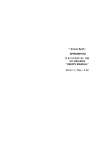
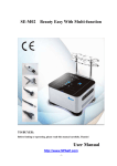
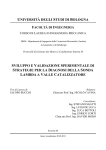
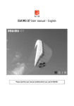
SMC BATTERY CHARGER
USER’S MANUAL
SMC
USER’S MANUAL
1
INDEX
1 INDEX.................................................................................................................................... 1
2 INTRODUCTION................................................................................................................... 2
2.1 INTRODUCTION AND REFERENCES.................................................................................................. 2
2.2 GLOSSARY........................................................................................................................................... 2
2.3 DATA LABEL......................................................................................................................................... 2
2.4 HOW TO USE THE USER'S MANUAL.................................................................................................. 2
2.5 RESPONSIBILITY DISCLAIMER........................................................................................................... 3
3 SMC BATTERY CHARGER – DESCRIPTION..................................................................... 3
3.1 SMC BATTERY CHARGER – INTRODUCTION................................................................................... 3
3.2 TECHNICAL DATA................................................................................................................................ 3
3.2.1 PHYSICAL FEATURES...................................................................................................................... 3
3.2.2 TECHNICAL DESCRIPTION ............................................................................................................. 3
4 INSTALLATION OF THE CHARGER................................................................................... 4
4.1 ELECTRICAL INSTALLATION OF THE CHARGER.............................................................................. 4
4.1.1 VEHICLE BLOCK FUNCTION............................................................................................................ 4
4.2 MAIN SUPPLY VOLTAGE PRESET ..................................................................................................... 5
5 OPERATIONS....................................................................................................................... 5
5.1 HOW TO CONNECT THE CHARGER.................................................................................................. 5
5.2 START OF THE CHARGE..................................................................................................................... 5
5.3 CHARGE OPERATIONS....................................................................................................................... 5
5.3.1 CHARGE CYCLE............................................................................................................................... 6
5.4 END OF CHARGE................................................................................................................................. 6
5.5 EMERGENCY STOP............................................................................................................................. 7
6 TROUBLE SHOOTING......................................................................................................... 7
7 TECHNICAL DOCUMENTS.................................................................................................. 7
Code: SMC-TVH Version: 01 Date: 24/08/2005
Page 1 of 7
SMC BATTERY CHARGER
USER’S MANUAL
2 INTRODUCTION
2.1 INTRODUCTION AND REFERENCES
This manual includes instructions and suggestions for the users of ENERGIC Plus SMC battery
chargers.
The code and the version of this manual are written on the bottom of each page. If you need more
copies please specify Code and Version.
Before starting to use your ENERGIC Plus SMC battery charger please read these instructions carefully.
2.2
GLOSSARY
Attention:
WUIa curve =
2.3
Read this section before proceeding!
Here you'll find an explanation of the technical terms used in the manual.
CHARGE CURVE - Described in the DIN 41774 norm;
DATA LABEL
A data label is located on the back side of the cabinet. It contains the following data:
•
•
•
•
•
•
•
•
•
•
CE make;
Model;
Serial number;
Weight;
Input voltage;
Maximum input current (A);
Maximum power consumption (KVA);
Input frequency;
Voltage of the battery (output voltage);
Maximum output current (output current).
2.4
HOW TO USE THE USER'S MANUAL
This manual includes all the information for the final user of ENERGIC Plus SMC battery
chargers.
Installation and maintenance operations can be done by qualified personnel only.
The user’s manual is an important part of the charger, therefore it must be kept in good condition for the
lifetime of the charger. It should be kept in a dry and clean place, always available to the users.
To indicate important instructions, in this manual the following pictures are used:
“Caution: ”
This operation can be dangerous for the user.
“Attention: ” This operation is important for the good working of the charger.
During this operation there is a risk of an electrical shock.
Code: SMC-TVH Version: 01 Date: 24/08/2005
Page 2 of 7
SMC BATTERY CHARGER
USER’S MANUAL
2.5
RESPONSIBILITY DISCLAIMER
The manufacturer of ENERGIC Plus SMC battery chargers will not be responsible for damages caused
by the chargers in these situations:
• The charger is not installed properly by a qualified electrician;
• The charger is not used according to the instructions included in this manual;
• The charger is not connected to the correct input supply (see technical label on the box);
• The charger has been modified without the authorization of the manufacturer;
• Non-original or wrong spare parts are used in the charger;
3
SMC BATTERY CHARGER – DESCRIPTION
3.1
SMC BATTERY CHARGER – INTRODUCTION
ENERGIC Plus SMC battery chargers have been designed to charge Pb batteries.
These units can convert the AC main supply in a DC output at the correct voltage, in order to charge the
battery cells.
These chargers have been designed and optimized to be used with electric vehichles and to be
mounted on board.
3.2
TECHNICAL DATA
3.2.1 PHYSICAL FEATURES
Mass:
Main supply cable:
Battery connection cables:
Motor blocking signal:
5 - 40 Kg depending on the model (see data label on box);
Grey multiple cable;
Red cable / marked with symbol +;
Black cable / marked with symbol - ;
Grey bipolar cable.
3.2.2 TECHNICAL DESCRIPTION
These are the principal devices included in the charger, available to the user:
• External box;
• Control electronic board;
• Main switch 0-1;
• No.2
Cables for battery connection;
• No.1
Cable for main supply connection;
• No.1
Cable for vehicle block during the charge.
Inside the charger there are the following devices, not available to the user:
• Power transformer;
• Rectifier;
• Microprocessor controlled electronic card with power relais;
• Output fuse;
• Plugs for voltage setting;
• Motor blocking relay.
Code: SMC-TVH Version: 01 Date: 24/08/2005
Page 3 of 7
SMC BATTERY CHARGER
USER’S MANUAL
4
INSTALLATION OF THE CHARGER
Conditions of use:
-
Operating temperature: 5°C to 45°C;
Storage temperature:
-20°C to 60°C;
Relative humidity: less than 75%;
4.1
•
•
•
Attention:
The charger can be installed by qualified personnel only.
Attention:
This unit operates on 230 V AC +/- 10%, 50Hz.
Check that the unit’s operating voltage is identical to your local power supply.
Check that the unit’s maximum input power is available from your power supply.
Attention:
To prevent fire or shock hazard, do not expose the unit to rain or moisture.
Do not use the unit in presence of flammable gas, because it can
generate sparks.
Attention:
To avoid electrical shock, do not open the cabinet. Refer servicing to qualified
personnel only.
Attention:
Allow adequate air circulation to prevent internal heat buildup.
Do not place the unit near materials that may block the ventilation slots.
Do not install the unit near heat sources such as radiators or air ducts, or in a
place subject to direct sunlight, excessive dust, mechanical vibration or shock.
Please take care about positioning and fixing of the charger inside the vehicle;
these must assure a correct air flow and a portection against every kind of phisical
or electrical damage.
ELECTRICAL INSTALLATION OF THE CHARGER
Check the efficiency of earth circuitry (yellow/green wire);
Connect the charger to the battery using an adequate connector;
Check the condition of the main supply plug;
4.1.1 MOTOR BLOCKING FUNCTION
Attention:
These settings can be done by qualified personnel only.
For more information please
manufacturer.
contact
the
ENERGIC Plus SMC battery chargers are equipped with a relay that can be used to block the vehicle
motor when the charger is connect to the main supply and the main switch is ON.
This safety function will prevent the user to start the vehicle while it's being charged.
In order to ensure a safe operation, it's mandatory to implement this function. This can be accomplished
by connecting the two control wires (grey bipolar cable) in series with the control circuitry of the vehicle.
Code: SMC-TVH Version: 01 Date: 24/08/2005
Page 4 of 7
SMC BATTERY CHARGER
USER’S MANUAL
4.2
MAIN SUPPLY VOLTAGE PRESET
Attention:
•
•
•
•
•
•
•
These settings can be done by qualified personnel only.
For more information please contact the manufacturer.
Disconnect the charger from main supply and battery;
Open the cabinet;
Find the plugs for tension setting;
Disconnect the wire A from the original plug (position 2);
Connect the wire A to the desired position. Check the table to find the correct position;
Close the cabinet;
Connect the charger to main supply.
POSITION
VOLTAGE
4
250
3
240
5
OPERATION
5.1
HOW TO CONNECT THE CHARGER
•
•
2
230
1
220
Set the main switch
to position “0”;
Connect the charger to the main supply.
5.2
START OF THE CHARGE
The charger can be turned on only when the battery and the main supply are correctly connected.
Set the main switch
to position “1”; the light inside the switch and the led “CHARGE ON” will lights
on.
After 5 seconds the charge start and the first green LED (which corresponds to the first charge phase)
lights on (see chapter 5.3.1).
Attention:
5.3
ENERGIC Plus SMC chargers are programmed to do a complete cycle of
charge, however it’s recommended to survey the operations when the battery
must remain connected to the charger for more than 12 hours (example: weekends)
CHARGE OPERATIONS
Attention:
The operations described in this chapter are done by ENERGIC Plus SMC
chargers automaticly.
Code: SMC-TVH Version: 01 Date: 24/08/2005
Page 5 of 7
SMC BATTERY CHARGER
USER’S MANUAL
5.3.1 CHARGE CYCLE
The current of charge follows the WUa curve, as described in the DIN 41774 Norm, while the LED
“CHARGE ON” remains on.
2° PHASE U
1° PHASE W
The charging cycle is divided in 2 phases (with reference to the front panel of the charger).
1° Phase: W [Constant Power]
When the charge starts, the battery voltage is around 2.00 V/cell and the current reaches the maximum
value. During this phase the current decreases and the voltage increases, up to the threshold value (2,5
V/cell). At this point, the charge passes to the next phase.
This phase has a security timer of 8 hours. If the battery don't reaches the threshold value in 8 hours the
charger pass automatically to the the next phase. This function prevent the risk of overheat of the
battery.
2° Phase: U [Constant Voltage]
The charge continues at constant voltage, while the current decreases. This phase continue for 4 hours.
At the end the cycle is complete.
The front panel show another phase, but this feature isn't implemented in this model.
5.4 END OF CHARGE
When the battery is completely charged the charger is turned off.
The LED “CHARGE ON” turns off and the 3° phase led remains on.
Attention:
Before disconnecting the battery, check it is not being charged. If it is charging
(led “CHARGE ON” light on), turn off the charger using the main switch
, to
avoid sparks between connectors.
Code: SMC-TVH Version: 01 Date: 24/08/2005
Page 6 of 7
SMC BATTERY CHARGER
USER’S MANUAL
5.5 EMERGENCY STOP
If the charge is not normally completed within 20 hours, the electronic control stops the charger
automatically.
In this case the led “CHARGE ON” is off and the 3° phase led is blinking.
This condition isn't normal and is strictly recommended to find the source of the problem. Please see to
the following chapter or contact the manufacturer.
6
TROUBLE SHOOTING
Attention: The operations described in this chapter can be done by qualified personnel only.
•
When
•
•
•
•
•
•
•
•
Charge current is too high:
• Check the battery cells for short circuits;
• The main supply voltage is too high, then it’s necessary to reset the charger. See chapter
4.2;
• If the battery is old, it's voltage increases slowly, and this can cause a high final charge
current. Keep the battery under supervision against overheats during the charge;
• Contact the manufacturer;
•
Charge current is too low:
• The main supply voltage is too low, then it’s necessary to reset the charger. See chapter 4.2;
• Contact the manufacturer;
• Check the output fuse;
•
The lamp inside the main switch is allways off:
• The main switch
may be in position "0", or else the main supply is not present;
• Check the connections between main supply and charger;
• Verify that the power available on the main supply is sufficient for the charger;
7
the main supply is connected, nothing happens on the control panel:
The main switch
may be in position "0", or else the main supply is not present;
Check the connections between main supply and charger;
Verify that the power available on the main supply is sufficient for the charger;
Verify fuses of the main supply;
Check the connection between battery and charger;
Check the output fuse;
Contact the manufacturer;
TECHNICAL DOCUMENTS
This manual includes the following technical documents:
ELECTRIC DIAGRAM
Code: SMC-TVH Version: 01 Date: 24/08/2005
Page 7 of 7