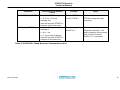
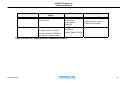
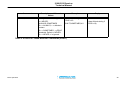
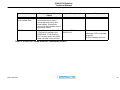
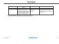
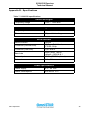
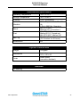
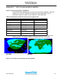
1
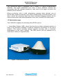
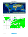
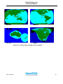
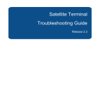
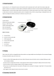
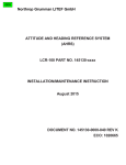
2100LR12 OPERATOR’S MANUAL
Release: April 2001
2100LR12 Receiver
Technical Manual
About this manual
This manual has been released by:
OmniSTAR BV
Dillenburgsingel 69
2263 HW Leidschendam
The Netherlands
Phone: +31-70-3170900
Fax:
+31-70-3170919
Email: [email protected]
www.omnistar.nl
Manual release date:
April 2001
Manual part number:
MAN-2100LR12-00
The information in this manual applies to 2100LR12 receivers with
Software version 1.41
(release date August 10, 2000)
DSP (L-Band) version 3.3 (release date August 27, 2000)
ARM (GPS) version 3.7
Specifications are subject to change without notice.
Copyright Notice
© 2001 OmniSTAR BV. All rights reserved. No part of this manual may be copied,
photocopied, reproduced, translated, or reduced to any electronic medium or
machine-readable form without prior written consent from OmniSTAR BV.
Issue April 2001
ii
2100LR12 Receiver
Technical Manual
OmniSTAR Limited Warranty
This warranty applies only to normal usage of the product. It does not apply to units
or electronic circuit boards which are defective due to improper installation or
handling. Physical damage due to lightning or other electrical discharge and units
subjected to fresh or salt water contamination is not covered. OmniSTAR reserves
the right not to warrant the product if, upon request, sufficient proof of
recommended installation compliance as laid out in this manual is not provided. No
other warranties are expressed or implied. No other warranties exist.
One-Year Limited Hardware Warranty
OmniSTAR reserves the right to repair and/or replace, at its option, any part or
parts found to be defective, provided such defects, in their opinion, are due to faulty
material or workmanship and are not caused by unauthorised or improper repair or
abuse, or normal wear. Purchaser shall be responsible for shipping and insurance
of the returned product for repair under this warranty. OmniSTAR will pay shipping
and insurance for the product's return to purchaser provided that the product
returned proves to be defective under this limited warranty.
OmniSTAR BV and its operating companies world-wide (Fugro NV), warrants this
product to be free from defects in workmanship and material for a period of one
year from the date of original sale by OmniSTAR or its authorised dealers, to the
original purchaser or end user.
OmniSTAR assumes no responsibility for any consequential or incidental losses or
damages of any nature with respect to the use of this product.
Issue April 2001
iii
2100LR12 Receiver
Technical Manual
Table of contents
OmniSTAR Limited Warranty................................................................................ iii
List of figures .......................................................................................................... v
List of tables............................................................................................................ v
1. Introduction......................................................................................................... 1
1.1 The OmniSTAR system.................................................................................. 1
1.2 Subscription type............................................................................................ 2
2. Factors affecting system performance............................................................. 4
2.1 Number of visible satellites ............................................................................ 4
2.2 Multipath......................................................................................................... 4
2.3 Position Dilution of Precision (DOP)............................................................... 5
2.4 Satellite elevations ......................................................................................... 5
2.5 Differential corrections ................................................................................... 5
3. Installation........................................................................................................... 6
3.1 System parts list ............................................................................................. 6
3.2 Installing the 2100LR12 ................................................................................. 6
3.2.1 Installation Considerations...................................................................... 6
3.2.2 Electrical Grounding Requirements ........................................................ 7
3.2.3 Counter Electromagnetic Force (CEMF)................................................. 7
3.2.4 Cable Installation Considerations ........................................................... 7
3.2.5 Antenna Location .................................................................................... 8
3.2.2 Power considerations.............................................................................. 9
3.2.3 Mounting ............................................................................................... 10
3.2.3 Connecting to external equipment ........................................................ 11
3.3 Start up procedure........................................................................................ 11
3.3.1 LED INDICATORS ................................................................................ 12
3.4 Subscription (re) activation........................................................................... 15
4. Connections ...................................................................................................... 16
4.1 Electrical Interface Description..................................................................... 16
4.2 Cables .......................................................................................................... 17
5. Troubleshooting ............................................................................................... 19
5.1 Contacting OmniSTAR ................................................................................. 20
Appendix A, Receiver Commands ...................................................................... 21
Appendix B - Specifications ................................................................................ 36
Appendix C – List of communication satellites ................................................. 38
Appendix D – List of reference stations ............................................................. 40
Appendix E - NMEA 0183 ..................................................................................... 45
E.1 NMEA introduction ....................................................................................... 45
E.2 NMEA 0183 message options ..................................................................... 45
E.3 NMEA 0183 message format....................................................................... 46
E.4 NMEA 0183 sentences ................................................................................ 47
E.4.1 GGA – GPS Fix Data............................................................................ 47
E.4.2 GLL – Geographic Position – Latitude/Longitude................................ 47
Issue April 2001
iv
2100LR12 Receiver
Technical Manual
E.4.3 GSA – GPS DOP and Active Satellites ................................................ 48
E.4.4 GSV – Satellite Information .................................................................. 48
E.4.5 RMC – Recommended Minimum Configuration ................................... 49
E.4.6 VTG – Track Made Good and Ground Speed ...................................... 49
E.4.7 ZDA – Time and Date ........................................................................... 50
E.4.8 GST – GPS pseudorange noise statistics ............................................ 50
Appendix F – OmniSTAR subscription agreement form................................... 52
List of figures
Figure 1: OmniSTAR 2100LR12 ............................................................................. 2
Figure 2: World coverage map for the OmniSTAR service ................................. 3
Figure 3: EMS spotbeam for coverage in Europe................................................ 3
Figure 4: Multipath.................................................................................................. 4
Figure 5: Zener Diode Installation ......................................................................... 7
Figure 6: 2100LR12 Mounting Details ................................................................. 10
Figure 7: LED Location and Colours................................................................... 12
Figure 8: 9 pin sub-D connector on data cable.................................................. 16
Figure 9: User and Antenna Cable ...................................................................... 17
Figure 10: 2100LR12 Command cable ................................................................ 18
Figure 11: Troubleshooting ................................................................................. 19
Figure 12: Location and coverage area per satellite ......................................... 38
Figure 13: Location and coverage area per satellite ......................................... 39
List of tables
Table 1: Red LED Function .................................................................................. 12
Table 2: 1st Yellow LED Function ....................................................................... 13
Table 3: 2nd Yellow LED Function ...................................................................... 13
Table 4: Green LED Function............................................................................... 14
Table 5: Pin-out for I/O Connector ...................................................................... 16
Table 6: 2100LR12 L-Band Receiver Commands............................................... 21
Table 7: 2100LR12 specifications ....................................................................... 36
Table 8: Worldwide satellite frequencies and symbol rates ............................. 38
Table 9: Reference stations on EMS ................................................................... 40
Table 10: Reference stations on EA-SAT ........................................................... 41
Table 11: Reference stations on AP-Sat ............................................................. 42
Table 12: Reference stations on AM-Sat ............................................................ 43
Table 13: Reference stations on Optus .............................................................. 43
Table 14: Reference stations on AMSC .............................................................. 44
Table 15: NMEA 0183 message options ............................................................. 45
Table 16: Description of the GGA message ....................................................... 47
Issue April 2001
v
2100LR12 Receiver
Technical Manual
Table 17: Description of the GLL message ........................................................ 48
Table 18: Description of the GSA message........................................................ 48
Table 19: Description of the GSV message........................................................ 49
Table 20: Description of the RMC message ....................................................... 49
Table 21: Description of the VTG message ........................................................ 50
Table 22: Description of the ZDA message ........................................................ 50
Table 23: Description of the GST message ........................................................ 51
Issue April 2001
vi
2100LR12 Receiver
Technical Manual
1. Introduction
The Global Positioning System (GPS) is a reliable, continuous, all-weather
navigation system which is operated by the United States Government. At the time
of writing, the space segment of GPS includes a constellation of 28 satellites, which
orbit the earth at an altitude of approximately 22.000 km.
These satellites (Space Vehicles or SV’s) transmit radio signals containing precise
satellite time and position information. By receiving four or more of these signals a
3-dimensional position can be computed.
Although GPS provides an acceptable level of performance for some users, many
applications demand a more reliable and precise position than GPS alone can
provide. In such cases Differential GPS (DGPS) must be used.
The purpose of DGPS is to minimize the effects of atmospheric and satellite errors
on the position determination. In order to achieve this a reference GPS receiver
must be installed at a point of known coordinates. This receiver uses the radio
signals from each of the GPS satellites which are in view to measure so-called
pseudo-ranges to these satellites. Because the exact locations of the satellites and
the reference receiver are known, it is then possible to determine the difference
between the actual and the expected pseudo-ranges (pseudo-range correction or
PRC).
In order to provide compatibility for exchanging this correction data, a standard has
been developped by the Radio Technical Commission for Maritime Services
Special Committee 104. This standard is commonly known as RTCM SC-104.
When RTCM version 2.0 correction data from the reference receiver is applied to a
nearby GPS receiver, the position accuracy will be substantially better than if
stand-alone GPS were to be used.
1.1 The OmniSTAR system
The 2100LR12 is one of several DGPS receivers which have been designed to
work with the world-wide OmniSTAR service.
The OmniSTAR DGPS system delivers corrections from an array of reference
stations which are located all around the world (see figures 2 and 3 on page 3).
The RTCM correction data from these reference stations is provided to
OmniSTAR’s two global Network Control Centres (NCC) , where the corrections
are decoded, checked, and repackaged in a highly efficient format for broadcast.
Issue April 2001
1
2100LR12 Receiver
Technical Manual
The OmniSTAR data is broadcast over a series of L-band communication
satellites. The signal transmitted over each of these satellites contains the
corrections from the reference stations in and close to the region in which this
satellite can be received.
When a receiver with a valid subscription receives data through one of
OmniSTAR’s satellite channels it will output a differentially corrected position. The
way in which the correction data from each individual reference station will be
used in the position calculation depends on the user’s OmniSTAR subscription.
1.2 Subscription type
The 2100LR12 supports the following OmniSTAR service:
• Virtual Base Station (VBS), where the data from multiple reference stations is
used in the processor software to produce enhanced corrections for the user's
location. This service provides optimal position accuracy with a minimum
dependence on the user’s location. The VBS service can be obtained on a
continental, country or regional basis.
Figure 1: OmniSTAR 2100LR12
Issue April 2001
2
2100LR12 Receiver
Technical Manual
Figure 2: World coverage map for the OmniSTAR service
Figure 3: EMS spotbeam for coverage in Europe
Issue April 2001
3
2100LR12 Receiver
Technical Manual
2. Factors affecting system performance
The 2100LR12 has proven to be a high-quality positioning device.
The accuracy that the user can obtain depends on several factors, including:
•
•
•
•
•
Number of visible satellites
Multipath
Dilution of Precision (DOP)
Satellite elevations
Differential correction
2.1 Number of visible satellites
A minimum of four satellites are required to calculate a 3-dimensional position.
In general it can be said that every increase in the number of visible satellites
will result in an increase in the system’s accuracy. As the GPS satellites orbit
around the earth the number of visible satellites will change in time. The GPS
constellation has been designed so as to provide a minimum of 4 visible
satellites at any location at all times. The number of visible satellites can
decrease due to blockage by objects such as trees and buildings.
2.2 Multipath
It is possible for satellite signals to reflect off large nearby objects such as
buildings, cars or even the ground, thereby resulting in an erroneous distance
measurement. This phenomenon is known as multipath. Multipath can cause
significant errors in the position determination and it is therefore important to
place the receiver in an environment which is free of large reflective surfaces. It
is also recommended to mount the receiver directly onto a surface, while
maintaining a clear view of the sky in all directions.
Figure 4: Multipath
Issue April 2001
4
2100LR12 Receiver
Technical Manual
2.3 Position Dilution of Precision (DOP)
The Position Dilution of Precision (PDOP) is a measure of the satellite
geometry. The lower the PDOP value, the more accurate the GPS position will
be. By default the 2100LR12 is configured to output position data as long as the
Position Dilution of Precision does not exceed 10.
2.4 Satellite elevations
The signal from a satellite which is low on the horizon will travel a greater
distance through the atmosphere. This results in a lower signal strength and a
delayed reception, thereby causing erroneous and noisy data. By default the
2100LR12 is configured to ignore any satellites which have an elevation angle
lower than 5°.
2.5 Differential corrections
For accurate positioning it is essential that the differential corrections are
received. In order to ensure reception of the OmniSTAR satellite signal it must
be prevented that the line of sight towards the satellite is blocked by objects
such as trees and buildings.
Multipath reflections can cause destructive interference, thereby significally
decreasing the signal strength. It is therefore recommended to mount the
2100LR12 directly onto a surface in a reflection free environment.
Although the 2100LR12 has been designed to provide optimal system
performance under most circumstances, it is possible, due to the nature of radio
communications, that system performance degrades due to local interference
sources.
Issue April 2001
5
2100LR12 Receiver
Technical Manual
3. Installation
This chapter contains instructions and recommendations for the installation of the
2100LR12.
3.1 System parts list
A shipment usually consists of:
•
•
•
•
•
•
•
2100LR12 receiver
Combined data/power cable
This manual
Command cable (optional)
Parasol Antenna
Antenna Cable 1.2 m Blue
Toolkit software
(part nr: REC-2100LR12)
(part nr: CBL-2100-02)
(part nr: MAN-2100-00)
(part nr: CBL-2100-00)
(part nr: ANT-SATL-00)
(part nr: CBL-2100-03)
(part nr: SOF-2100-00)
3.2 Installing the 2100LR12
In order to provide for a smooth and successful installation, please observe the
following instructions and recommendations.
3.2.1 Installation Considerations
•
Determine preferred location of each unit prior to beginning installation.
Consider cable length, connector attachment space (cable bend radius),
stowing excess cable, moisture, chemical corrosion, vibration and heat
exposure.
•
Before drilling holes, consider using existing hardware and hardware
locations. Avoid drilling holes that may damage other equipment
(example: structural frame members, electrical cables or fluid lines).
•
High vibration and high temperature locations should be avoided
whenever possible.
•
In applications where vibration exceeds 6 Gs acceleration, shock mounts
are required. Refer to Customer support for mounting recommendations.
•
Vehicle primary power contains voltages that may be harmful to personnel
and equipment. Detach battery cable connector from battery -ve
(negative) terminal before attempting connection to any power terminals.
Issue April 2001
6
2100LR12 Receiver
Technical Manual
3.2.2 Electrical Grounding Requirements
The 2100LR12 requires a perfect ground to vehicle structure at the negative line
in the receiver power input. The L-Band receiver should read zero Ohms to
where the battery negative terminal is connected to vehicle ground.
3.2.3 Counter Electromagnetic Force (CEMF)
A potential problem inherent in any installation of electronic systems in a vehicle
is Counter Electromagnetic Force (CEMF).
CEMF is caused when relays or solenoids connected to the common vehicle DC
power bus are de-energised. The voltage produced may exceed -400 volts.
CEMF is produced by equipment such as the following:
•
•
•
•
•
Differential correction
Electric Fan Brakes
Air Conditioners
Starter relays
Electric Pump Relays
CEMF is more than sufficient to damage, or cause erratic operation of any
electronic system also connected to DC power.
CEMF can be eliminated by installing diodes at the relays and solenoids that
cause the CEMF, and more importantly, at the power supply cable connection of
the 2100LR12 system. A 47V, 5W, Zener diode (1N5368 or equivalent) should
be connected.
Battery +ve (positive) supply
Ground
Zener Diode
Figure 5: Zener Diode Installation
3.2.4 Cable Installation Considerations
•
Cables must be correctly installed for optimum system operation.
Therefore, the following should be noted:
•
Do not route an L-Band receiver remote antenna cable along with the
cabling of any other radio system. This can cause interference between
both systems.
Issue April 2001
7
2100LR12 Receiver
Technical Manual
•
If at all possible, do not run L-Band receiver antenna cables parallel to
other radio system cabling closer than 30 centimetres.
•
If cables must cross, ensure that they cross at an angle of 90°. This
minimises the possibility of interference.
•
As far as is practicable, ensure that cables and I/O connectors are unique
and fit only in their allocated location.
•
Avoid routing cables along-side power generator cabling and other high
electrical noise sources. This can cause interference.
•
Do not kink or force cables into sharp bends that may damage the cables
and cause system failure.
•
After installation, ensure that excess cable in looped and clamped or tied
safely away from any control cables, fuel lines, hydraulic lines or moving
parts.
•
When stowing over length cables, form loops not less than 150mm
minimum cable bend radius.
•
Cable routing must avoid high temperature exposure
(e.g. exhaust manifold).
3.2.5 Antenna Location
Antenna position is critical to system performance. The following conditions must
be met for optimum system operation:
•
2100LR12 antenna must be mounted at least 1 to 5 metres away from
transmitting antennae of any frequency. Closer positioning may cause
overloading of receiver RF circuits.
•
The 2100LR12 antenna should be mounted at the highest practical point
that will give a good view of the horizon and be as near to level as
possible.
•
The 2100LR12 Receiver must be located along the vehicle centre line to
ensure correct data accuracy.
Issue April 2001
8
2100LR12 Receiver
Technical Manual
•
The receiver has a clear line of sight towards the L-band communication
satellite. Since these satellites are located above the equator, they are to
the South of Europe at an elevation angle of 20° (Oslo) to 45° (Athens).
3.2.2 Power considerations
Power can be supplied to the 2100LR12 by connecting 9.5 – 40 VDC on the
fused power wire. The other power wire should be connected to ground.
Only supply power after the cable has been connected to the 2100LR12,
never attach or detach a powered cable to/from the unit.
The power consumption of the 2100LR12 is 400 mA at 12 V.
In order to protect the equipment from power surges a 2 A in-line fuse has been
adopted in the positive power wire. Do not run the equipment with the fuse
bypassed as this will void warranty.
Issue April 2001
9
2100LR12 Receiver
Technical Manual
3.2.3 Mounting
Figure 6: 2100LR12 Mounting Details
1.
Determine the proper mounting location(s) for the 2100LR12 receiver.
2.
Verify that cables are of sufficient length and routing meets all the
conditions listed.
3.
Position the 2100LR12 receiver on the desired mounting location.
4.
Use the 2100LR12 receiver as a template and mark the drill locations four
places for the mounting bolts, then remove the receiver.
5.
Drill ¼” holes at the marked locations.
Issue April 2001
10
2100LR12 Receiver
Technical Manual
3.2.3 Connecting to external equipment
The 2100LR12 uses the RS232 protocol to communicate with external
equipment.
The 2100LR12 is normally shipped for communicating with the following settings:
•
9600 bps
•
8 bits
•
No parity
•
1 stop bit
•
flowcontrol none
The 2100LR12 is normally configured to output the following NMEA sentences:
•
GGA
•
GSA
•
VTG
•
ZDA
Other NMEA sentences are available (see Appendix D).
The standard data cable allows the receiver to output NMEA data. A so-called
command cable (part nr: CBL-2100-00) is available as an option for experienced
users who need to change settings. Please contact OmniSTAR for more
information.
3.3 Start up procedure
Consider the following guidelines before starting to work with the system:
•
•
•
•
•
Normally the receiver software is already set to the user’s specific requirements
Make sure that the 2100LR12 has a clear line of sight to the communication
satellite
Connect the 9 pin sub-D connector to a PC (or other logging device), which has
been set to communicate using 9600,8,N,1
Connect the power cable to an appropriate power supply (9.5 to 40 VDC) which
has been turned off
Turn on the power supply
When the unit is used for the first time, has not been used for a long period of time,
or has been moved a long distance it may take up to 12.5 minutes to start
outputting NMEA messages. The outputting of differentially corrected NMEA may
take up to 40 minutes under these circumstances.
Issue April 2001
11
2100LR12 Receiver
Technical Manual
3.3.1 LED INDICATORS
The 2100LR12 receiver has 4 LED’s that serve as status indicators. These LED’s
should all be illuminated solid (non-blinking) when the receiver is powered ON
and has a valid GPS and differential solution. Otherwise, the LED’s can be in
various states (blinking, on solid or off). The LED operations are described in the
following tables.
2nd Yellow
1st Yellow
Green
Red - Power
Figure 7: LED Location and Colours
LED
Function
Red LED
This LED should be on solid once power
(Right-hand side)
is applied to the receiver.
This is the only LED that is not under
Computer control.
Table 1: Red LED Function
Issue April 2001
12
2100LR12 Receiver
Technical Manual
LED
1st Yellow LED
Function
This LED serves two purposes.
•
At power-on it will blink 3 to 4
times, once per second, and then
go off. If it fails to blink, the L-Band
differential processor is likely to
have failed. If it does not stop
blinking the GPS processor is the
likely culprit.
•
After a minute or so, this LED
should go on solid yellow to
indicate that GPS has lock. This is
true even if differential corrections
are not available.
Table 2: 1st Yellow LED Function
LED
nd
2
Yellow LED
Function
This LED can be in several states
Off – L-Band differential signal has not
been received.
•
Flickering on and off – the receiver
is close to acquiring the L-Band
•
Blinking at a steady rate – L-Band
differential signal has been
acquired, but the Bit-Error-Rate is
high. Generally, this will not affect
performance, but it is a warning of
weak signal strength.
•
On ‘Steady’ – L-Band differential
signal has been acquired and
signal strength is good.
Table 3: 2nd Yellow LED Function
Issue April 2001
13
2100LR12 Receiver
Technical Manual
LED
Green LED
Function
This LED will remain off until a differentially
corrected GPS solution is available. It will
blink at a steady rate if the solution has not
converged to the accuracy specified by the
$JLIMIT command and will become solid
green after the solution has converged. (The
$JLIMIT sets the threshold for the RMS
residual error and this error gives a rough
indication of expected user accuracy. Note
however, that it is not a direct measure of
accuracy, factors such as constellation
geometry must also be taken into account.
The default value for $JLIMIT is 10 meters).
Table 4: Green LED Function
Other Conditions: If at start-up, the two yellow and one green LED’s blink in
sequence 3 times, then the subscription on the receiver has expired.
Issue April 2001
14
2100LR12 Receiver
Technical Manual
3.4 Subscription (re) activation
If the OmniSTAR subscription on your 2100LR12 has not been activated yet, will
expire soon or has been expired already, a new subscription can be sent over the
satellite link.
The procedure for obtaining a new subscription is:
•
•
•
•
Fill in the OmniSTAR subscription agreement form (see Appendix F)
Fax the form to OmniSTAR BV at +31-70-3170919
At the agreed time of activation make sure your receiver is outside and in a
place where it will be able to receive signals from the communication satellite
Have the receiver switched on at the time of activation
At the time of activation a series of commands containing the new expiry date and
other subscription information will be sent over the satellite link to your 2100LR12
receiver.
If your receiver does not start outputting differential position data within 45 minutes
after the activation time, please contact OmniSTAR by phone at +31-70-3170900.
Issue April 2001
15
2100LR12 Receiver
Technical Manual
4. Connections
4.1 Electrical Interface Description
The RF connector is a standard TNC 50 Ohm female connector. There are 5V DC
present when the unit is powered up to bias the Low Noise Amplifier (LNA) in the
remote antenna. Care should be taken not to connect or disconnect while powered
up.
The I/O connector is a standard metal eight-pin circular Bendix style connector
PT02E-12-8P. The pin-out is defined in Table 5.
Pin No.
Name
Description
A
+ Vin
9.5 to 40V DC, 5W, power input
(12V DC, 0.417A)
B
1 PPS
One pulse per second, 1µs width, rising edge
aligned, TTL levels
C
Aux. Tx
Auxiliary communication port, transmit line,
RS232 levels (NMEA)
D
Aux. Rx
Auxiliary communication port, receive line,
RS232 levels (NMEA)
E
Diag. Tx
Primary communications port, transmit line,
RS232 levels. (Command)
F
Diag. Rx
Primary communications port, receive (input)
line, RS232 levels (Command)
G
Mark in
Manual Mark input line, TTL levels, falling
edge triggered.
H
Ground
Digital, power and analogue ground
Table 5: Pin-out for I/O Connector
NMEA Port
5
4
9
3
8
Pin#
2
7
1
6
DB9 Female
1
2
3
4
5
6
7
8
9
Signal
N/A
DATA OUT*
N/A
N/A
GND
N/A
N/A
N/A
N/A
Figure 8: 9 pin sub-D connector on data cable
Issue April 2001
16
2100LR12 Receiver
Technical Manual
4.2 Cables
The 2100LR12 is normally shipped with a combined data/power cable and an
antenna cable. For experienced users who need to change settings a command
cable is available.
Figure 9: User and Antenna Cable
Issue April 2001
17
2100LR12 Receiver
Technical Manual
Figure 10: 2100LR12 Command cable
Issue April 2001
18
2100LR12 Receiver
Technical Manual
5. Troubleshooting
Use to following diagram to identify and solve problems in the event that the
2100LR12 does not output a differentially corrected position.
Is unit
outside, with
clear view of
sky?
No
NMEA
output?
Yes
Clear line of sight
towards L-band
communication
satellite?
No
Yes
No
Place unit
outside,
with clear
line of sight
to satellite
Is power
supply
outputting
proper
voltage?
No
Yes
Has the unit been
outside for at least
45 minutes?
No
Keep unit
outside for
at least 45
minutes
Yes
Valid subscription on
receiver?
No
Contact
OmniSTAR to
obtain a
subscription
Yes
Receiver on land, in
region for which
subscription has
been applied?
Place unit
outside,
with clear
view of sky
Yes
No
Go to a
valid region
Faulty cable,
contact
OmniSTAR
Yes
Turn off power
supply, disconnect
cable.
Turn on power
supply.
Power on pins
E & F?
(see figure 6)
Turn on/replace
power supply
No
No
Fuse
blown?
Yes
Replace 2A fuse
Faulty data cable,
or receiver failure,
contact
OmniSTAR
Yes
Receiver failure,
contact
OmniSTAR
Figure 11: Troubleshooting
Issue April 2001
19
2100LR12 Receiver
Technical Manual
5.1 Contacting OmniSTAR
If you encounter a technical problem during installation or system operation,
please contact OmniSTAR at +31-70-3170900.
Issue April 2001
20
2100LR12 Receiver
Technical Manual
Appendix A, Receiver Commands
Note
The word(s) contained in brackets [ ] in the ‘Command’ column in the following pages indicate(s) an optional addition to the
particular command line. They may be omitted or added (without the brackets) however the user sees fit.
Note
Configuration changes are not saved between power cycles unless the $JSAVE command is issued.
The $JFREQ and the $4STRING commands are exceptions. They are automatically saved after issuing.
Command
$JBIN,msg,r[,OTHER]
Description and Allowed Values
Example
Turn On/Off binary message.
Turn on 99 at 1Hz.
R = 0, 0.2, 1 or 5Hz
$JBIN, 99, 1.
(0 turns message off).
Msg = 1, 2, 97, 98 or 99 (more
may be added. Msg 97, 98 and 99
only support 1Hz).
Use the keyword ‘OTHER’ to
configure to the other port).
Reply
$>Binary message
99 will begin
outputting every
second.
(See ‘Appendix Binary Message
Type 99’ for further
details).
Table 6: 2100LR12 L-Band Receiver Commands
Issue April 2001
21
2100LR12 Receiver
Technical Manual
Command
$JASC, GP[GGA, GLL,
VTG, GSV, RMC, GSA,
ZDA,GST], r, [OTHER]
Description and Allowed
Values
Turn On/Off NMEA msg x at
rate r.
Example
Reply
Turn on GGA.
$>
$JASC, GPGGA, 1
NMEA string GGA will begin
outputting every second.
R = 0, 0.2, 1 or 5Hz (0 turns
message off).
Options supported are:
$JASC, GPGGA, r
$JASC, GPGLL, r
$JASC, GPVTG, r
$JASC, GPGSV, r *
$JASC, GPRMC, r
$JASC, GPGSA, r *
$JASC, GPZDA, r
$JASC, GPGST, r **
Options with * only available at
0.2Hz or 1Hz. Optional with **
only available at 1Hz. (Use the
keyword ‘OTHER’ to configure
to the other port).
Table 6: 2100LR12 L-Band Receiver Commands (contd.)
Issue April 2001
22
2100LR12 Receiver
Technical Manual
Command
$J4STRING[,r][,OTHER]
Description and Allowed
Values
Configure port to output
NMEA strings: GPGGA,
GPVTG, GPGSA, and
GPZDA.
Example
Configure other port
to output 4 Strings of
NMEA at 4800 baud.
$J4STRING, OTHER
The output rate of each string
is 1Hz and all other strings on
the port are turned off.
Reply
$>
$>
NMEA strings GGA, VTG,
GSA and ZDA, will begin
outputting at 4800 BAUD
every second from the other
port.
Makes the change permanent
(i.e. saves configuration).
r = 4800, 9600 (if r is omitted,
the rate defaults to 4800).
(Use the keyword ‘OTHER’ to
configure to the other port).
Table 6: 2100LR12 L-Band Receiver Commands (contd.)
Issue April 2001
23
2100LR12 Receiver
Technical Manual
Command
$JASC,RTCM,r[,OTHER]
Description and Allowed
Values
Example
Reply
Turn On/Off RTCM msg r.
Turn on RTCM.
$>
r = 0, 0.2 or 1 (0 turns
message off).
$JASC,RTCM,1
RTCM message will begin
outputting.
Turn on diag I.
$>
$JASC,DI,1
Diagnostic message 1 will
begin outputting every second
(see Format for reply to
$JASC, D1,1 command).
(Use the keyword ‘OTHER’ to
configure to the other port).
$JASC,Dx,r[,OTHER]
Turn on/off Diagnostics
message x.
r = 0 or 1 Hz.
x = 1 (more may be added).
(Use the keyword ‘OTHER’ to
configure to the other port).
Table 6: 2100LR12 L-Band Receiver Commands (contd.)
Issue April 2001
24
2100LR12 Receiver
Technical Manual
Command
Description and Allowed
Values
Example
$JASC,MSG,r[,OTHER]
Configure to turn On/Off
general text messages (these
begin with $RMSG).
Turn text messages on.
$>
$JASC,MSG, 1
Text Messages will begin
outputting for any direct
text messages being
broadcast over the
network.
r = 0 for Off
r = I for On
(Use the keyword ‘OTHER’ to
configure to the other port).
Reply
Table 6: 2100LR12 L-Band Receiver Commands (contd.)
Issue April 2001
25
2100LR12 Receiver
Technical Manual
Command
$JAIR,m
Description and Allowed
Values
Turn on air mode so that
receiver responds better to
higher dynamics and signal
fades.
Example
Turn on air-mode.
Reply
$>Air Mode: ON
$JAIR, 1
m = 0 turn off air mode
m = I turn on air mode
Note, this comes on
automatically once the speed
exceeds 30m/s, unless it has
been deliberately turned off.
Table 6: 2100LR12 L-Band Receiver Commands (contd.)
Issue April 2001
26
2100LR12 Receiver
Technical Manual
Command
$JCMODE,m,[OTHER]
Description and Allowed
Values
Example
Configure port to accept
RTCM.
Configure other port to
accept RTCM.
m = 0 port accepts normal
commands.
$JCMODE,1,0THER
Reply
$>
m = I port accepts RTCM and
will ignore other commands.
$JOFF[,OTHER]
$JSAVE
Turn off all messages except
the $JASC,MSG (those
beginning with $RMSG)
Shut off all messages
that are output to other
port.
(Use the keyword ‘OTHER’ to
configure to the other port).
$JOFF,OTHER
Save the current configuration
(make permanent).
Save setting changes.
$JSAVE
$>
$> Saving Configuration.
Please Wait
$> Save Complete
Table 6: 2100LR12 L-Band Receiver Commands (contd.)
Issue April 2001
27
2100LR12 Receiver
Technical Manual
Command
$JSHOW
Description and Allowed
Values
Show the current
configuration.
Example
Show status of port
and receiver
configurations
Reply
$>JSHOW,data
(see Format for reply to
$JSHOW command)
$JSHOW
$JBAUD,r
Configure the baud rate.
r = 4800, 9600 and 19200
(Use the keyword ‘OTHER’ to
configure to the other port).
Configure other port at
4800 baud.
$>
$JBAUD,4800,OTHER
Table 6: 2100LR12 L-Band Receiver Commands (contd.)
Issue April 2001
28
2100LR12 Receiver
Technical Manual
Command
$JALT,c,v
Description and Allowed
Values
Configure altitude aiding.
c = NEVER,
ALWAYS,SOMETIMES
Example
Use altitude aiding at
PDOP=4.0
$JALT,SOMETIMES,4.0
Reply
$>
(Uses Altitude aiding if
PDOP>4.0)
If c = ALWAYS, v = altitude in
meters.
If c = SOMETIMES, v =PDOP
threshold. Default = NEVER.
If c = NEVER, v is ignored.
Table 6: 2100LR12 L-Band Receiver Commands (contd.)
Issue April 2001
29
2100LR12 Receiver
Technical Manual
Command
$JLIMIT,v
Description and Allowed
Values
Set residual threshold for
Green LED. ‘v’ ranges from
1.0 to 50.0 meters.
Example
Set green LED
threshold to 2 meters.
Reply
$>
$JLIMIT,2.0
You must have differential and
the rms pseudo-range residual
less than v before the green
LED becomes solid (nonblinking).
Default = 10.0.
$JMASK, e
Configure elevation mask e =
0, 1, 2, ... 60 degrees.
Default = 0.0
Use 5-degree mask.
$>
$JMASK,5
Table 6: 2100LR12 L-Band Receiver Commands (contd.)
Issue April 2001
30
2100LR12 Receiver
Technical Manual
Command
$JRESET[,ALL]
Description and Allowed
Values
Reset configuration to default
and makes this permanent.
Equivalent to SLIMIT, 10
Example
Reply
Clear only the user
configuration.
$> Saving Configuration.
Please Wait
$JRESET
$> Save Complete
Show Receiver
information
$>JI, 810 123, 1,3,2502 1
998,01/06/1980,06/30/1
999,2.4,20
$JMASK,5 $JALT,NEVER,0
$JOFF $JAIR,0 $JFREQ,0
and $JOFF,OTHER, followed
by a $JSAVE.
If ALL is included, also resets
ALMANAC and clears spot
beams to defaults.
$JI
Display receiver unit number,
fleet, hardware version,
production date code,
subscription begin date,
subscription expiration date,
ARM and DSP software
version
$JI
Table 6: 2100LR12 L-Band Receiver Commands (contd.)
Issue April 2001
31
2100LR12 Receiver
Technical Manual
Command
$JT
Description and Allowed
Values
Example
Reply
Display receiver type
(e.g. 2100LR12).
Show receiver type
Display subscription expiration
date.
Show current expiration.
$JPOS,Lat,Lon
Set your current location to be
used at start-up until a new
location is found. Good for
first-time start-ups in new spot
beam.
$JPOS,33.11,-111.25
$>
$JLBEAM
Display current spot beams.
Show spot beam
information.
$>JLBEAM,
Information (see Format
for reply to $JLBEAM
command).
$JK
$>JT,SLXg
$JT
$>JK,12/31/1999
$JK
$JLBEAM
Table 6: 2100LR12 L-Band Receiver Commands (contd.)
Issue April 2001
32
2100LR12 Receiver
Technical Manual
Command
Description and Allowed
Values
Example
Reply
$JFREQ,Frequency in
KHz,Symbol Rate
Force differential frequency
and symbol rate to these
values and stop using spot
beam tables. A frequency
value of 0 will re-enable use of
spot beam tables.
$JFREQ,1551489,1200
$>
$JDCO,v
Set the frequency offset of the
TCXO (at L1) stored in the
ARM. Here, v is a double in
Hz. It is only used if the ARM
does not have a nav solution.
Zero the TCXO value
$JDCO,0.0.
$>
Message if GPS is already
acquired:
$>GPS Already has lock.
Table 6: 2100LR12 L-Band Receiver Commands (contd.)
Issue April 2001
33
2100LR12 Receiver
Technical Manual
Command
$JOMS
Description and Allowed
Values
Example
Reply
Display OmniSTAR
Subscription Information.
Show raw subscription
information:
$>JOMS,DRY,ALL,VBS,0,01/06/
1980,06/30/1999,0,0, 1E00, 1.19
$>JOMS,Opt,Source,Type,Ac
crReductionStartDate,EndDat
e,HourGlass,ExtentionTime,
LinkVector,Software Version.
$JOMS
(see Format for reply to $JOMS
command).
Table 6: 2100LR12 L-Band Receiver Commands (contd.)
Issue April 2001
34
2100LR12 Receiver
Technical Manual
Command
$JOMR
Description and Allowed
Values
Example
Display Subscription Region
Information.
Show subscription
region information.
This command will respond
with a set of Lat and Lon in
radians and a radius distance
in meters. The receiver will
work in the radius of a
specified area if an inclusion
zone is given (positive radius
value) and will not work within
the radius of the specified
area if an exclusion zone is
given (negative radius value).
$JOMR
Reply
$>JOMR, 1,0.994787, 1.605694,4500000.000
$>JOMR,2,0.000000,0.
000000,0.000000
$>JOMR,3,0.000000,0.
000000,0.000000
$>JOMR,4,0.000000,0.
000000,0.000000
$>JOMR,5,0.000000,0.
000000,0.000000
(see Format for reply to
$JOMR command).
Table 6: 2100LR12 L-Band Receiver Commands (contd.)
Issue April 2001
35
2100LR12 Receiver
Technical Manual
Appendix B - Specifications
Table 7: 2100LR12 specifications
OmniSTAR Engine
Frequency Range
1525 – 1559 MHz
GPS Engine
Frequency
1575.42 MHz
Channels
12 parallel tracking
Serial Interface
Serial Protocol
Data output
RS232
Mil Spec Bulk Head,
PT02E-12-8p
9 pin sub-D
4800, 9600, 19200
default = 9600,8,N,1
NMEA (RTCM optional)
Data rate
1 Hz, 5Hz
Connector (receiver end)
Connector (user end)
Baud rate
Power Specifications
Power supply
9.5 – 40 VDC
Power consumption
400 mA at 12 V
Issue April 2001
36
2100LR12 Receiver
Technical Manual
Environmental Specifications
Operating Temperature
-34°C to 72°C
Storage Temperature
-50°C to 85°C
Humidity
100% condensing
10mm Displacement, 10 – 17
Hz
6 Gs to 2000 Hz, Operating
MIL-STD-202F,
Methode 213, Procedure J
MIL-STD-810E,
Method 510.3, Procedure I
MIL-STD-202F, Method 101
Condition II
(5% Solution for 48 hours)
4G
Vibration
Shock
Dust
Salt Fog
Acceleration
Physical Characteristics
Weight
750 gram
Dimensions
lxwxh
140 x 140 x 40
Finish
White epoxy
(corrosion resistant)
Approvals
CE Marking
Issue April 2001
37
2100LR12 Receiver
Technical Manual
Appendix C – List of communication satellites
List of communication satellites
The following table presents a list of L-band communication satellites, which will
enable you to use your 3100LM over the entire world (depending on your
subscription type you might only be entitled to a restricted area).
Table 8: Worldwide satellite frequencies and symbol rates
Satellite Channel
Frequency (MHz)
Symbol Rate
Eik EMS
1531.2300
2438
EA-SAT
1535.1525
2438
AP-SAT
1535.1375
2438
AM-SAT
1535.1375
2438
OPTUS
1558.5100
2436
AMSC East
1556.8250
2436
AMSC Centre
1554.4970
2436
AMSC West
1551.4890
2436
The position (marker) and coverage-area of each satellite are displayed in the
following figures. The AMSC satellite coverage-area’s are in one figure.
Eik EMS
EA-SAT
Figure 12: Location and coverage area per satellite
Issue April 2001
38
2100LR12 Receiver
Technical Manual
AP-SAT
AM-SAT
OPTUS
AMSC
Figure 13: Location and coverage area per satellite
Issue April 2001
39
2100LR12 Receiver
Technical Manual
Appendix D – List of reference stations
The following tables present the current list of reference stations, which are
broadcast over communication satellites used by OmniSTAR. The list of reference
stations change regularly to improve the network.
Table 9: Reference stations on EMS
Nr Station
1 Tromso, Norway
ID Data
690 YES
2
3
4
5
6
7
8
9
10
630 YES
Orlandet, Norway
Torshavn, Faroes
Rogaland, Norway
Aberdeen, Scotland
Shannon, Ireland
Leidschendam, The Netherlands
Toulouse, France
Vienna, Austria
Istanbul, Turkey
620
580
571
530
521
431
480
410
YES
YES
YES
YES
YES
YES
YES
YES
11 Baku, Azerbaijan
400 YES
12 Faro, Portugal
371 YES
13 Malta
351 YES
14 Crete, Greece
340 YES
15 Alexandria, Egypt
310 YES
16 Bodo, Norway
122 YES
17 Visby, Sweden
229 YES
Ny Alesund, Spitsbergen
101
NO
Vardo, Norway
114
NO
Trondheim, Norway
126
NO
Issue April 2001
40
2100LR12 Receiver
Technical Manual
Table 10: Reference stations on EA-SAT
Nr Station
1 Cape Town, South Africa
ID Data
335 YES
2
3
4
5
6
7
8
9
10
262
235
095
045
015
011
043
050
060
Johannesburg, South Africa
Walvis Bay, Namibia
Luanda, Angola
Pointe-Noire, Congo
Nairobi, Kenia
Sao Tome
Douala, Cameroon
Abidjan, Ivory Coast
Lagos, Nigeria
YES
YES
YES
YES
YES
YES
YES
YES
YES
11 Blantyre, Malawi
155 YES
13 Abu Dhabi, UAE
016 YES
14 Kuwait
290 YES
15 Alexandria, Egypt
310 YES
16 Crete, Greece
340 YES
17 Las Palmas, Canaries
280 YES
18 Orlandet, Norway
630 YES
19 Rogaland, Norway
580 YES
22 Faro, Portugal
371 YES
23 Baku, Azerbaijan
400 YES
24 Durban, South Africa
305 YES
Rio de Janeiro, Brazil
226
NO
Rio de Janeiro, Brazil
225
NO
Mumbai-Arvi, India
191
NO
Issue April 2001
41
2100LR12 Receiver
Technical Manual
Table 11: Reference stations on AP-Sat
Nr
2
3
4
9
10
11
12
13
14
15
Station
Karratha, Australia
Darwin, Australia
Broome, Australia
Okinawa, Japan
Singapore
Miri, Malaysia
Vung Tua, Vietnam
Hong Kong
Seoul, S. Korea
Kota Kinabalu, Malaysia
ID Data
215 YES
125
185
261
010
042
012
220
370
061
YES
YES
YES
yes
YES
YES
YES
YES
YES
16 Bali, Indonesia
096 YES
17 Mumbai-Arvi, India
191 YES
19 Subic Bay, Phillipines
151 YES
20 Kuwait
290 YES
21 Abu Dhabi, UAE
016 YES
23 Kuantan, Malaysia
041 YES
24 Satun, Thailand
018 YES
25 Bangkok, Thailand
141 YES
27 Sapporo, Japan
430 YES
Issue April 2001
42
2100LR12 Receiver
Technical Manual
Table 12: Reference stations on AM-Sat
Nr
1
2
3
4
5
6
7
8
9
10
Station
Houston, Texas
Cocoa Beach, Florida
Long Island, New York
Carmen, Mexico
Punta Arenas, Chile
Guayaquil, Ecuador
Rio de Janeiro, Brazil
St. Johns, Newfoundland
Dartmouth, Nova Scotia
Recife, Brazil
ID Data
100 YES
120
333
110
210
202
225
470
440
075
YES
YES
YES
YES
YES
YES
YES
YES
YES
11 Port Of Spain, Trinidad
111 YES
12 Caracas, Venezuela
112 YES
13 Buenos Aires
345 YES
Table 13: Reference stations on Optus
Nr Station
1 Perth, Australia
ID Data
325 YES
2
3
4
5
6
7
8
9
16
18
215 YES
Karratha, Australia
Darwin, Australia
Townsville, Australia
Brisbane, Australia
Melbourne, Australia
Pt Augusta, Australia
Kalgoorlie, Australia
Cobar, Australia
Bali, Indonesia
Bathurst, Australia
125
195
275
385
326
315
316
096
336
YES
YES
YES
YES
YES
YES
YES
YES
YES
22 Auckland. NZ
022 YES
26 Dunedin, NZ
026 YES
31 Broome, Australia
185 YES
Issue April 2001
43
2100LR12 Receiver
Technical Manual
Table 14: Reference stations on AMSC
Nr Station
1 San Diego, Ca, USA
ID Data
140 YES
2
3
4
5
6
7
8
9
10
11
555 YES
Everrett, Wa, USA
Mercedes, Tx, USA
Houston, Tx, USA
Pensacola, Fl, USA
Cocoa Beach, FL, USA
Fayetteville, NC, USA
Long Island, NY, USA
Duluth, Mn, USA
Redding, Ca, USA
Carmen, Mexico
Issue April 2001
160
100
150
120
130
333
491
180
110
YES
YES
YES
YES
YES
YES
YES
YES
YES
44
2100LR12 Receiver
Technical Manual
Appendix E - NMEA 0183
E.1 NMEA introduction
NMEA 0183 is an interface protocol created by the National Marine Electronics
Association. The latest release of NMEA 0183 is Version 2.2. This protocol was
originally established to allow marine navigation equipment to share information.
NMEA 0183 is a simple, yet comprehensive ASCII protocol, which defines both the
communication interface and the data format.
E.2 NMEA 0183 message options
The OmniSTAR 2100LR12 is normally configured to output the GGA, GSA and
VTG NMEA 0183 sentences (GGA, GSA, RMC for John Deere customers).
Sentences can be added or removed at the customer’s request. The output rate is
normally configured at a 1-second interval.
Table 15: NMEA 0183 message options
Message Sentence
GGA
GLL
GSA
GSV
RMC
GST
VTG
ZDA
Issue April 2001
Description
GPS Fix Data
Geographic Position – Latitude/Longitude
GPS DOP and Active Satellites
Satellite Information
Recommended Minimum Configuration
GPS pseudorange noise statistics
Track Made Good and Ground Speed
Time and Date
45
2100LR12 Receiver
Technical Manual
E.3 NMEA 0183 message format
NMEA 0183 allows a single source (talker) to transmit serial data over a single
twisted wire pair to one or more receivers (listeners). The NMEA 0183 protocol
covers a broad array of navigational data. This is separated into discrete
messages, which convey a specific set of information. The NMEA 0183 message
structure is outlined below.
$IDMSG,D1,D2,D3,D4,……..,Dn*CS[CR][LF]
“$”
The “$” signifies the start of message.
ID
The Talker identification is a two letter mnemonic which
describes the source of the navigation information. The GP
identification signifies a GPS source.
MSG
The message identification is a three letter mnemonic which
describes the message content and the number and order of the
data fields.
“,”
Commas serve as deliminators for the data fields.
Dn
Each message contains multiple data fields (Dn) which are
delimited by commas.
“*”
The asterisk serves as a checksum delimiter.
CS
The checksum field contains two ASCII characters which indicate
the hexadecimal value of the checksum.
[CR][LF]
The carriage return [CR] and line feed [LF] combination terminate
the message.
NMEA messages vary in length, but each message is limited to 79 characters or
less. This length limitation excludes the “$” and the [CR] [LF]. The data field block,
including delimiters, is limited to 74 characters or less.
Issue April 2001
46
2100LR12 Receiver
Technical Manual
E.4 NMEA 0183 sentences
In this section each message is described in more detail.
E.4.1 GGA – GPS Fix Data
The GGA message includes time, position and fix related data for the GPS
receiver.
GGA,hhmmss.ss,ddmm.mmmmm,s,dddmm.mmmmm,s,q,n,uu,pp.p,±aaaaa.aa,M,
±xxxx.xx,M,sss,aaaa
Table 16: Description of the GGA message
Field Number
1
2,3
4,5
6
7
8
Description
UTC of Position
Latitude in degrees (d) and minutes(m), N (North) or S (South).
Longitude in degrees (d) and minutes(m), E(East) or W (West).
GPS Quality Indicator: 0=No GPS, 1=GPS, 2=DGPS.
Number of Satellites in Use.
Horizontal Dilution of Precision (HDOP).
9,10
11,12
13
14
Antenna Altitude in Meters, M = Meters.
Geodial Separation in Meters, M = Meters. *
Age of Differential GPS Data. **
Differential Reference Station ID (0000 – 1023)
NOTES:
* Geodial Separation is the difference between the WGS-84 earth ellipsoid and
mean-sea-level (MSL), or when expressed in a formula:
HeightMSL = HeightEllipsoid - HeightGeoid
** Time in seconds since the last RTCM SC-104 message type 1 or type 3 update.
E.4.2 GLL – Geographic Position – Latitude/Longitude
The GLL message contains the latitude and longitude of the present position, the
time of the position fix and the status.
GLL,ddmm.mmmmm,s,dddmm.mmmmm,s,hhmmss.ss,A
Issue April 2001
47
2100LR12 Receiver
Technical Manual
Table 17: Description of the GLL message
Field Number
Description
1,2
Latitude in degrees (d) and minutes(m), N (North) or S (South).
3,4
Longitude in degrees (d) and minutes(m), E (East) or W (West).
5
UTC of Position.
6
Status: A = Valid, V = Invalid.
E.4.3 GSA – GPS DOP and Active Satellites
The GSA message indicates the GPS receivers operating mode and lists the
satellites used for navigation and the DOP values of the position solution.
GSA,a,m,xx,xx,xx,xx,xx,xx,xx,xx,xx,xx,xx,xx,pp.p,hh.h,vv.v
Table 18: Description of the GSA message
Field Number
1
2
3 to 14
15
16
17
Description
Mode: M = Manual, A = Automatic.
Current Mode 1 = Fix not available, 2 = 2D fix, 3 = 3D fix.
PRN numbers of the satellites used in the position solution. *
Position Dilution of Precision (PDOP).
Horizontal Dilution of Precision (HDOP).
Vertical Dilution of Precision (VDOP)
NOTES:
* When less than 12 satellites are used, the unused fields are null.
E.4.4 GSV – Satellite Information
The GSV message contains GPS satellite information. Null fields occur where no
data is available due to the number of tracked satellites.
GSV,t,m,n,ii,ee,aaa,ss,…,ii,ee,aaa,ss
Issue April 2001
48
2100LR12 Receiver
Technical Manual
Table 19: Description of the GSV message
Field Number
1
2
3
4,8,..
5,9,..
6,10,..
7,11,..
Description
Total number of messages
Message number (1-3)
Total number of satellites in view
Satellite number
Elevation in degrees (0-90)
Azimuth (true) in degrees (0-359)
SNR (0-99 dB)
E.4.5 RMC – Recommended Minimum Configuration
The RMC message contains the recommended minimum GPS data.
RMC,hhmmss.ss,a,ddmm.mm,n,ddddmm.mmm,w,z.z,y.y,ddmmyy,d.d,v
Table 20: Description of the RMC message
Field Number
1
2
3,4
5,6
7
8
9
10
11
Description
UTC of position
Status (A = valid, V = invalid)
Latitude in degrees (d) and minutes(m), N (North) or S (South).
Longitude in degrees (d) and minutes(m), E (East) or W (West).
Ground speed in knots
Track made good, referenced to true north
UTC date of position fix in day, month, year
Magnetic variation in degrees
Variation sense (East/West)
E.4.6 VTG – Track Made Good and Ground Speed
The VTG message conveys the actual track made good (COG) and the speed
relative to the ground (SOG).
VTG,ttt.tt,T,ttt.tt,M,ggg.gg,N,ggg.gg,K
Issue April 2001
49
2100LR12 Receiver
Technical Manual
Table 21: Description of the VTG message
Field Number
1,2
3,4
5,6
7,8
Description
Track Made Good in Degrees True.
Track Made Good in Degrees Magnetic.
Speed Over the Ground in Knots.
Speed Over the Ground in Kilometer’s per Hour.
E.4.7 ZDA – Time and Date
The ZDA message contains UTC, the day, the month and the year of the local
time zone.
ZDA,hhmmss.ss,dd,mm,yyyy,shh,mm
Table 22: Description of the ZDA message
Field Number
1
2
3
4
5
6
Description
UTC.
Day (0 – 31).
Month (0 – 12).
Year.
Local Zone Description Hours (± 13 Hours). *
Local Zone Description Minutes.
NOTES:
* Local zone description is the number of whole hours added to local time to obtain
UTC. The zone description is always negative for eastern longitudes. A GPS
receiver cannot independently identify the local time zone offsets.
E.4.8 GST – GPS pseudorange noise statistics
This message is used to support receiver autonomous integrety monitoring
(RAOM). Pseudorange measurement noise statistics can be translated in the
position domain in order to give statistical measures of the quality of the position
solution.
GGA,hhmmss.x.x,x.x,x.x,x.x,x.x,x.x,x.x,x.x*hh
Issue April 2001
50
2100LR12 Receiver
Technical Manual
Table 23: Description of the GST message
Field Number
1
2
6
Description
UTC time of the GGA fix associated with this sentence
RMS value of the standard deviation of the range inputs to the
navigation process. Range inputs include pseudoranges and
DGPS corrections
Standard deviation of semi-major axis of error ellipse, meters
Standard deviation of semi-minor axis of error ellipse, meters
Orientation of semi-major axis of error ellipse
(degrees from true north)
Standard deviation of latitude error, meters
7
8
Standard deviation of longitude error, meters
Standard deviation of altitude error, meters
3
4
5
Issue April 2001
51
2100LR12 Receiver
Technical Manual
Appendix F – OmniSTAR subscription agreement form
The next page contains the form which is necessary to apply for a new OmniSTAR
subscription for your 2100LR12 receiver.
Issue April 2001
52