1
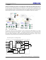
RobuNetTM Mesh Radio Enabled Aggregator
Model No. : CWW185-2j
USER MANUAL V. 1.1
This document is confidential and legally privileged. If you are not an authorized representative of an
intended recipient, you are prohibited from using, copying or distributing the information.
If you are interested in discussing the document further, please feel free to contact us directly via email at
[email protected].
Robulink Technology (Shenzhen) Ltd. All Right Reserved.
Robulink Technology (Shenzhen) Ltd.
CONTENT
ROBUNET MESH RADIO ENABLED AGGREGATOR........................................................................... - 1 CWW185-2J ................................................................................................................................................. - 1 USER MANUAL .......................................................................................................................................... - 1 1.
GENERAL: .......................................................................................................................................... - 3 1
.
1
1
.
2
WORKING PRINCIPLE ........................................................................................................................- 3 MAIN CHARACTERISTICS: .................................................................................................................- 4 -
2.
MAIN TECHNICAL PARAMETERS................................................................................................. - 4 -
3.
MAIN FUNCTION............................................................................................................................... - 6 3.1
PARAMETER SETTING:.......................................................................................................................- 6 3.2
DATA COLLECTION & PROCESSING ....................................................................................................- 6 3.2.1 Energy data................................................................................................................................ - 6 3.2.2 Memory capacity........................................................................................................................ - 6 3.3
AUTOMATIC RE-READING & ALARMING .............................................................................................- 6 3.4
TIME SYNCHRONIZATION ..................................................................................................................- 7 3.5
FIELD READING ................................................................................................................................- 7 3.6
EVENT LOG ......................................................................................................................................- 7 3.7
REMOTE UPGRADING ........................................................................................................................- 7 3.8
SPECIFIC USER MONITORING .............................................................................................................- 7 3.9
DATA RETENTION UNDER OUTAGE .....................................................................................................- 7 -
4.
INSTALLATION AND USAGE........................................................................................................... - 7 4.1
OUTLINE, INSTALLATION DIMENSION .................................................................................................- 7 4.3
PANEL OPERATION ............................................................................................................................- 9 4.4
INSTRUCTION FOR STATUS INDICATORS ..............................................................................................- 9 4.5
DISPLAY OF AGGREGATOR ...............................................................................................................- 10 4.5.1 Display format.......................................................................................................................... - 10 -
5.
TRANSPORTATION AND STORAGE............................................................................................. - 13 5.1
5.2
TRANSPORTATION ...........................................................................................................................- 13 STORAGE .......................................................................................................................................- 13 -
Robulink Technology (Shenzhen) Ltd.
-2-
All Right Reserved.
Robulink Technology (Shenzhen) Ltd.
1.
General:
CWW185-2j aggregator is the gateway in the AMI system through which the communication, between
backend network management software system and RobuNetTM Mesh radio enabled meters in the field, can
be built up. It is also a management device of local RobuNetTM wireless Mesh network, handling the storage
of meter reading data, all the communications to and from meters (uplink), all the communications to and
from backend network software system (downlink) which can be GPRS, CDMA and 3G by replacement of
different uplink WAN module. To facilitate the local access to the aggregator, an RS-485 is provided.
1.1
Working principle
The aggregator adopted the mature technology of mobile communication GPRS/CDMA/3G as its uplink
channel for data communication and RobuNetTM Mesh radio communication as its downlink channel. With
the use of 32 digit microprocessor(ARM7)and embedded programming technology, combined with the
non-volatile memory and RS485 serial communication interface, the aggregator has realized network
communication, automatic data collection, data storage and data management.
The following shows its working principle:
Memory
A
IR
B
C
A
Mesh
Radio
RS485
3
2b
i
t
M
C
U
B
GPRS
/CDMA
N
PSU
Backup PSU
Robulink Technology (Shenzhen) Ltd.
-3-
All Right Reserved.
Robulink Technology (Shenzhen) Ltd.
1.2 Main characteristics:
The aggregator’s circuit design and component selection are based on the consideration of a wide range of
environmental factors, which makes sure that the aggregator can work stably in a long term. Basically, the
accuracy will not be various upon changes in frequency, temperature or voltage. Small size, light weight,
good sealing property and high reliability make it run fairly well.
The uplink channel adopts the high-speed full-duplex communication modules GPRS/CDMA/3G network of
industrial grade. And the module construction outside is easy for replacement without open the whole
aggregator.
l GPRS/CDMA/3G module and RobuNetTM Mesh radio module can be replaced with no need to open
the main cover of aggregator.
l Intelligent mesh radio network simplifies the installation: self forming, and self configuration.
l Advanced routing algorithm is employed in the design of RobuNetTM Mesh radio network. There is
no limit of “Number of Hops” given certain scale of the network.
l Data rate of RobuNetTM Mesh radio network reaches 19.2kbps on-air, 9.6kbps for local data port.
l It adopts the advanced 32 digit embedded mass memory of industrial grade with CPU ARM7/9 and
8Mbit FLASH.
l It has the built-in rechargeable lithium battery of 900mAh 3.7V as the backup power supply so as to
make sure that the aggregator can communicate with the master station for one time when the power
is off.
l As the backup battery, the built-in non-rechargeable lithium battery can prevent the data of the
aggregator from loss and keep the calendar, clock and program running in a normal way while the
power is off. When powered off, the battery can support the running of the aggregator for 3
successive years.
l The built-in TCP/IP Protocol in the aggregator supports all modes of network communication and
the online upgrading of the network.
2.
Main technical parameters
item
Technical parameters
Basic performance parameters
Rated
operation 3×240/415V (3P 4W) (Un)
voltage
Un±20%Un (192V~288V)
Operation
voltage When voltage loss in one or two phase, the AC supply can
Range
keep the aggregator working and communicating
normally.
Power
Power consumption of the aggregator ≤ 1.5W under
consumption
normal operation, ≤ 3W when the battery is charging
It adopts the circuit of temperature compensation hard
clock. Within its working temperature range, the accuracy
Accuracy of the
of its clock is better than 0.5s/d; the accumulative error
clock
will be less than 30 second/ month within the temperature
range or when the power supply is cut off.
The inner environmental safe lithium battery of 1.2Ah
Backup
3.6V (non-chargeable) can save data and keep the clock
Power
chip working. The life of battery is more than 5 years.
supply
Without AC power supply, the built-in rechargeable
Robulink Technology (Shenzhen) Ltd.
-4-
All Right Reserved.
Robulink Technology (Shenzhen) Ltd.
lithium battery of 900mAh 3.7V can communicate with
the master station for one time at least.
processor
32 digit ARM7/9 and the embedded operating system
Memory capacity Not less than 8M
Altitude
≤1000M
Temperature range in +5℃~40℃
facility office
RH ≤ 75%
Indoor
-25℃~50℃
temperature range
RH ≤ 90%
Outdoor
-45℃~70℃
temperature range
RH ≤ 95%
Average life
≥10 years
The uplink communication channel:
Public communication network which is compatible with
Communication
GPRS/CDMA/PSTN/network; the communication part
channel
adopts the design of hot-swap and module for the
convenience of replacement and maintenance.
Response time
When received the command from the master station, the
aggregator will send response data back to the master
station within 10 second besides the time for the data
collection by meters.
The downlink RobuNetTM Mesh radio communication channel:
Operation frequency 915MHz--928MHz
band
Occupied bandwidth
≤250KHz
Data rate
19.2Kbps on-air; 9.6Kbps local port
Maximum
30dBm (E.I.R.P.)
transmission power
Single transmission <400 ms
period
Receiving sensitivity
[email protected] & 0.1%BER
Communication interface:
3 mutually separated RS485 interface (lightning
protection). The first RS485 interface is set as the
Photo-electricity
sub-meter reading interface, the second cascaded interface
communication
RS485 interface
(reserved), the third radio module calibration interface. IR
port is for communication by hand-held unit while the
PS/2 interface
PS/2 port is for local adjustment and maintenance.
Communication
The enterprise standard of HND
protocol
Insulation property:
Terminals of weak electricity against those of strong
electricity≥100MΩ/500V;
Insulation resistance
Insulation resistance between each group of terminals of
weak electricity ≥100MΩ/250V.
industrial frequency AC 2000V/1min
withstand voltage
Meet the requirements of electromagnetic compatibility
Electromagnetic
test
requested
by
standards
of
compatibility
IEC61000-4-2,IEC61000-4-3,IEC61000-4-4,
IEC61000-4-5, IEC61000-4-11, IEC61000-4-12
others
Overall dimension
weight
Length ×width ×height=312.5mm×178mm×141mm
Approximately 1.9kg
Robulink Technology (Shenzhen) Ltd.
-5-
All Right Reserved.
Robulink Technology (Shenzhen) Ltd.
TM
Note: RobuNet
3.
3.1
is a registered trademark of Robulink Technology Limit
Main function
Parameter setting:
The following parameters can be set remotely or through the local IR port:
a. aggregator number;
b. Relevant parameters of communication between aggregator and the master station (the
communication address of the master, the type of communication channel and etc.).
c. Meter reading schedule (meter reading interval, automatic meter reading date, meter reading time,
items to read and so on).
d. Index of meters’ addresses
e. Address of user’s meter
3.2
Data collection & processing
3.2.1
Energy data
According to the pre-set reading interval, the aggregator automatically read, collect and save the data of
real-time electric quantity, frozen energy of every meter at 0:00 at the end of the month and everyday frozen
energy at 0:00. The data of frozen energy for single-phase meter should be the export active total energy
while the data of frozen energy for three-phase meter should be: export active total energy, export active
energy at respectively tariff 1, 2, 3 and 4, and the export reactive total energy. Energy data should be marked
with time when they are saved.
The aggregator can froze and record load profile for export and import 30 minutes interval active and
reactive energy.
The aggregator can read and store 31 days’ of daily frozen energy of all meters under one transformer. It can
choose, by the switch, to read or not to read 31 times instantaneous energy (The defaulted status is not to
read the instantaneous energy).
3.2.2
Memory capacity
Each aggregator can monitor and manage not less than 500 single-phase meters or 200 three-phase
multi-functional meters. Based on the maximum number of users for which the aggregator is designed, each
user’s meter should store at least 60 days’ of daily frozen energy at 0:00 and 6 days’ frozen energy at 0:00 on
the last day of each month.
The aggregator is designed with special memory space, which can store the above two sorts of data
separately.
3.3
Automatic re-reading & alarming
The aggregator can automatically re-read the meter which it failed to read in its cycle reading during the
specified reading intervals.
The aggregator has the function of time re-reading, it will re-read the meters which it hasn’t been read. Time
for once reading: 10~60 seconds can be set through the master station. The defaulted is 10 second. Re-read
times: 3 times(default), the times can be set; the interval: 30 minutes (default), it also can be set.
The aggregator can send the alarming information to the master station when the meter data can’t be read
during the meter reading interval time:
Robulink Technology (Shenzhen) Ltd.
-6-
All Right Reserved.
Robulink Technology (Shenzhen) Ltd.
•When the aggregator adopts the uplink channel GPRS, it actively sends alarming information to the master
station;
•When dial the uplink channel through PSTN, the aggregator will send the alarming information to the
master station when it is reading the energy data of the latter.
3.4
Time synchronization
The aggregator has a time unit with temperature compensation. Within the working temperature range, the
accuracy of the inner clock is better than 0.5s/d. Within the temperature limit and when the power is off, the
accumulative error of the clock is less than 30 second per month.
The master station can remotely adjust the time of the aggregator, which in turn broadcast correct the time of
the meter at 22:00~23:00 everyday.
The aggregator can correct the time of the specified meters once every month. When error in the meter’s
clock is checked, the aggregator will immediately correct the time. The conditions for the meters with RTC
to receive broadcast time correction: time error should be within 5 mins, time correction interval: 24 hours.
The meters with software clock are not limited to these conditions.
3.5
Field reading
The aggregator has the local IR interface, which makes it able to do field reading by a hand-held reading unit
and then transmit the data to the master station system.
3.6
Event log
The aggregator can read and report events such as remote connection/disconnection, local
connection/disconnection, and load control groups, meter cover open, terminal cover open, power
on/off for meter, meter overvoltage and undervoltage and etc.
3.7
Remote upgrading
The aggregator’s firmware can be locally or remotely upgraded (the firmware include the main
firmware and the protocols for uplink and downlink channels), the meters also can be remotely
upgraded through the aggregator.
3.8
Specific user monitoring
The aggregator can select some meters under a transformer and randomly set them to be the focused ones so
as to give priority in management on them. The aggregator can set 6 meter at least to be of this kind.
The aggregator stores the data of export active total energy of the focused meters every hour. It can store at
least last 30 days’ historical data of export active total energy of the focused meters at sharp time.
3.9
Data retention under outage
When the power supply is interrupted for short time or long time, the aggregator shall not misread data and
also, have some measures to protect the data to make it safe for at least 4 months; when the power is on, the
data stored will not lose and the inner clock runs normally.
4.
4.1
Installation and usage
Outline, installation dimension
Robulink Technology (Shenzhen) Ltd.
-7-
All Right Reserved.
Robulink Technology (Shenzhen) Ltd.
L
CD
I
R
s
ta
tu
s
up
l
e
ft
r
ig
ht
d
o
wn
ba
c
k
o
k
DnRx
DnTx
s
el
fch
e
ck
R
S2
32
UpR
x
UpT
x
n
et
wo
rk
po
w
er
Outline dimension
de
bug
Dn
link
Upli
nk
n
etwork
Radio module figure
pow
er
ne
twork
Uplin
kTx
Upl
inkR
x
GPRS module figure
4.2
Connection diagram
UA
B
U
UC
UN
1
21
31
41
51
61
71
8192
02
12
223242526272
82
93
03
1
1.
Terminals 1-11 are AC sampling interfaces
2.
Terminals 12-15 are blank
3.
Terminal 16 is meter reading 485 A, 17 is meter reading 485B
Robulink Technology (Shenzhen) Ltd.
-8-
All Right Reserved.
Robulink Technology (Shenzhen) Ltd.
4.
Terminal 18 and 19 are link 485 A and 485B respectively
5.
Terminal 20 is radio 485A and 21 is radio 485 B
6.
22-31 are blank terminals
4.3 Panel operation
Panel consists of 160×160 LCD, 6 key-press and 8 indicators. Data and parameter of aggregator can be
accessed through key-press operation. Explanation for panel operation is as follows:
See the following for Meanings of 6 key-presses on terminal panel
:Indicates up arrow or number decreasing(0~9)
:Indicates down arrow or number increasing (0~9)
:Indicates left arrow or to front pages
:Indicates right arrow or to next pages
:Indicates entering into modification status or confirming command
:Indicates exiting modification status or back to previous menu.
Explanations for indicator lamps are as follows:
Green "status" indicator-if the indicator is on, it indicates the aggregator operates normally. If it’s off, it
indicates the aggregator operates abnormally.
Red "Self-check" indicator- if the indicator is on, it indicates the aggregator is self-check, or it will be off.
Red "Dnlink Rx" indicator- if the indicator is on, it indicates downlink channel is receiving data, or it will be
off.
Red "Dnlink Tx" indicator- if the indicator is on, it indicates downlink channel is transmitting data, or it will
be off.
Red "Uplink Rx " indicator- if the indicator is on, it indicates uplink channel is receiving data, or it will be
off.
Red "Uplink Tx " indicator- if the indicator is on, it indicates uplink channel is transmitting data, or it will be
off.
Red "network" indicator-- if the indicator is on, it indicates already entered master station, or it will be off.
Red "power" indicator-- if the indicator is on, it indicates the
power for communication module is normal,
or it will be off.
4.4 Instruction for status indicators
S/N
1
2
Name
Power indicator
(Power)
Explanation
GPRS/CDMA COM module
If aggregator is supplied normally, "power
indicator" lights all the time, or it will be off.
It is red ; when SIM card is not inserted or
Robulink Technology (Shenzhen) Ltd.
-9-
All Right Reserved.
Robulink Technology (Shenzhen) Ltd.
"Network" indicator
3
“Uplink Tx" indicator
4
" Uplink Rx " indicator
1
2
3
4
searching for GPRS network, it continuously
lights, 0.6 sec for each LED on and off; if
GPRS network is searched, this LED still
flashes, while 0.075 sec for LED on and 0.3
sec for LED off; It fast flashes when network is
normal, while slowly flashes as there is no
signal in the network.
When GPRS module is transmitting data on
uplink channel, the indicator flashes, or else it
will be off.
When GPRS module is receiving data on
uplink channel, the indicator flashes, or it will
be off.
Mesh radio module
When the indicator is on, it indicates the
“network
status
"
network is on normal status, while indicator is
indicator
off, it indicates that the network is abnormal.
When the mesh radio module is on uplink
“mesh radio uplink"
channel, the indicator will flash, or it will be
indicator
off.
When the mesh radio module is on downlink
“mesh radio downlink"
channel, the indicator will flash, or it will be
indicator
off.
“debug” indicator
Used for debugging radio module
4.5 Display of aggregator
4.5.1 Display format
The aggregator has a 160*160 dot-matrix LCD and it can display data of measurement points, aggregator
information, parameter configuration, aggregator management and maintenance, etc. Main menu on
aggregator as follows and the sub-menu of main menu can be viewed through pressing the pushbutton.
Main menu on aggregator
The means in the status bar on top of aggregator display as follows:
Signal intensity indication, the top is 4 bars, the worst is 1
bar. When the signal is only 1-2 bars, it indicates the
signal is weak and the communication is not stable; when
the signal is 3-4 bars, it indicates the signal is strong and
Robulink Technology (Shenzhen) Ltd.
- 10 -
All Right Reserved.
Robulink Technology (Shenzhen) Ltd.
the communication is stable
Communication mode indication:
G indicates GPRS mode
C indicates CDMA mode
Indicates current hour and minute, the format is HH:MM
Indicates current battery status
Annex 1: Key-press display mode
Press any key-press to enter main menu, then select the procedure to enter key-press search mode
according to the following menu.
When it is on key-press search mode and press once on the direction key “ Up” and “Dn”, it will display
one frame and display the contents. The aggregator will restore the previous display mode when stop pressing
the key-press.
Key-press operation structure as follows:
Annex 2: key-press setting mode
Press any key and enter main menu, then enter the key-press setting mode according to the following
procedures.
When it is on key-press setting mode, the followings can be set: data display of measurement points, aggregator
information, parameter setting, aggregator management and maintenance and etc. After pressing the key for 1
minute, the aggregator will restore its default display mode.
Menu item
Display screen
[G]
1.Meter energy query
00:00
Please input
Meter sequence
0001
Robulink Technology (Shenzhen) Ltd.
- 11 -
All Right Reserved.
Robulink Technology (Shenzhen) Ltd.
2.Aggregator info
[G]
00:00
Post code:
9999
Aggregator address: 00014
Software version:HND-AUS 1.21
Release date:
2008-08-15
Main IP address:203.86.31.195
Main Port :
6660
Backup IP address:203.86.31.195
Backup Port:6501
APN: CMNET
SIM card number:8986006019031910295
Local IP address: 10.10.190.232
Menu item
Display screen
[G]
Time setting
3. Parameter setting
Post code setting
Gateway IP and port
setting
10:17
Aggregator
Time setting
16-08-2008
10:17
[G]
00:00
Post code setting
9999
00014
[G]
00:00
Gateway IP address
-and port setting
Main IP address:
203.086.031.195
Main port:
06660
Robulink Technology (Shenzhen) Ltd.
- 12 -
All Right Reserved.
Robulink Technology (Shenzhen) Ltd.
[G]
APN setting
Menu item
Display screen
[G]
00:00
Reboot aggregator
Press Enter
To Reboot.
Press ESC
To Cancel.
[G]
00:00
Initialize data
Press Enter
To Initialize.
Press ESC
To Cancel.
[G]
00:00
Reset parameters
Press Enter
To Reset.
Press ESC
To Cancel.
Reboot aggregator
4. Management
Initialize data
Reset parameters
5.
5.1
00:00
APN setting
APN:
CMNET
Transportation and storage
Transportation
The aggregator should not be subject to violent impact during transportation and storage.
5.2
Storage
Storage temperature should be -40℃~75℃, relative humidity should be less than 95% and there is no
corrosive gas existing. It should be placed on the stands in the warehouse, piling up height should be less than 8
cartons
Robulink Technology (Shenzhen) Ltd.
- 13 -
All Right Reserved.