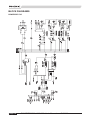
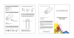
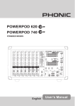
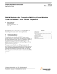
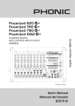
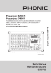
1
IMPORTANT SAFETY INSTRUCTIONS
1. Read these instructions before operating this
apparatus.
�������
2. Keep these instructions for future reference.
���� �� �������� �����
�� ��� ����
3. Heed all warnings to ensure safe operation.
4. Follow all instructions provided in this document.
5. Do not use this apparatus near water or in locations
where condensation may occur.
CAUTION: TO REDUCE THE RISK OF ELECTRIC SHOCK,
DO NOT REMOVE COVER (OR BACK)
NO USER SERVICEABLE PARTS INSIDE
REFER SERVICING TO QUALIFIED PERSONNEL
6. Clean only with dry cloth. Do not use aerosol or liquid
cleaners. Unplug this apparatus before cleaning.
The lightning flash with arrowhead symbol, within an equilateral triangle, is intended to alert the user to the presence
7. Do not block any of the ventilation openings. Install
in accordance with the manufacturer’s instructions.
of uninsulated “dangerous voltage” within the product’s
enclosure that may be of sufficient
8. Do not install near any heat sources such as radiators,
heat registers, stoves, or other apparatus (including
amplifiers) that produce heat.
9. Do not defeat the safety purpose of the polarized or
grounding-type plug. A polarized plug has two blades
with one wider than the other. A grounding type plug
has two blades and a third grounding prong. The wide
blade or the third prong is provided for your safety. If
the provided plug does not fit into your outlet, consult
an electrician for replacement of the obsolete outlet.
10. Protect the power cord from being walked on or
pinched particularly at plug, convenience receptacles,
and the point where they exit from the apparatus.
11. Only use attachments/accessories specified by the
manufacturer.
12. Use only with a cart, stand, tripod, bracket, or
table specified by the manufacturer, or sold with
the apparatus. When a cart is used, use caution
when moving the cart/apparatus
combination to avoid injury from tipover.
13. Unplug this apparatus during lighting
storms or when unused for long
periods of time.
14. Refer all servicing to qualified service personnel.
Servicing is required when the apparatus has been
damaged in any way, such as power-supply cord or
plug is damaged, liquid has been spilled or objects
have fallen into the apparatus, the apparatus has
been exposed to rain or moisture, does not operate
normally, or has been dropped.
!
magnitude to constitute a risk of electric shock to persons.
!
The exclamation point within an equilateral triangle is intended to alert the user to the presence of important operating and maintenance (servicing) instructions in the literature
accompanying the appliance.
WARNING: To reduce the risk of fire or electric shock, do
not expose this apparatus to rain or moisture.
CAUTION: Use of controls or adjustments or performance
of procedures other than those specified may result in
hazardous radiation exposure.
POWERPOD 745 / 865 / 885 PLUS
Molded Powered Mixer
page
FEATURES .............................................................................................................. 4
INTRODUCTION ...................................................................................................... 4
BASIC SETUP ......................................................................................................... 5
Getting Started ..................................................................................................... 5
Channel Setup ..................................................................................................... 5
INSTALLING RACK MOUNT KIT ............................................................................ 6
EXPANSION SLOT FOR WIRELESS MICROPHONE ............................................ 6
UTILIZING THE MOLDED MIXER........................................................................... 7
MAKING CONNECTIONS ....................................................................................... 8
Channel Inputs ..................................................................................................... 8
Master Section ..................................................................................................... 8
Rear Panel ........................................................................................................... 9
CONTROLS AND SETTINGS................................................................................ 10
Rear Panel ......................................................................................................... 10
Channel Controls ............................................................................................... 10
Digital Effect Section .......................................................................................... 11
Master Section ................................................................................................... 11
APPLICATION ...................................................................................................... 13
DIGITAL EFFECT TABLES.................................................................................... 14
DIMENSIONS......................................................................................................... 15
SPECIFICATIONS.................................................................................................. 16
BLOCK DIAGRAMS .............................................................................................. 18
Phonic reserves the right to improve or alter any information suppied within this document without prior notice.
V1.0 NOV. 12, 2004
INTRODUCTION
Thank you for choosing one of Phonic’s many quality powered mixers. The unique Powerpod Molded Powered Mixers
– innovated by the same talented engineers that have created a variety of mixers fantastic in style and performance in
the past – display similar proficiency that previous Phonic products have shown; with more than a few refinements, of
course. The all new Powerpod Molded Powered Mixers feature full gain ranges, amazingly low distortion levels, and
incredibly wide dynamic ranges, just showing the dominance these small machines will have in the mixing World.
The innovative features of Powerpods 745, 865 and 885 Plus are obvious at first glance. The new molded casing
provides not only added durability, but versatility that has previously been unavailable in mixers. Thanks to the
Powerpod Molded Mixers’ construction, you can simply place the mixer on a desk-top or other surface to sit at a 45°
angle for a better view of controls and easier utilization of the mixer. It is also possible to mount the new Powerpods on
a unique tri-pod stand, allowing users to bring the mixer up into their focal visual and dextral range.
Because of the over-all distinctiveness of the Powerpods 745, 865 and 885 Plus, we know by now you’re already
extremely eager to get started and see what this baby can do, but before you do we strongly urge you to take a look
through this manual. Inside, you will find important facts and figures on the set up, use and applications of your brand
new mixer. If you do happen to be one of the many people who flatly refuse to read user manuals, then we just urge
you to at least glance at the Instant Setup section. After glancing at or reading through the manual (we applaud you if
you do read the entire manual), please store it in a place that is easy to find, because, chances are, there is something
you missed the first time around.
FEATURES
Common Features
●
Angled molded cabinet
●
Dual 7-band graphic equalizers with feedback
detection system
●
Vocal eliminator for Karaoke
●
Solid Phonic System speaker enhancement
●
2 Super Hi-Z inputs optimized for direct input of
acoustic electric guitars and electric guitars or
basses
●
2 built-in limiters
●
3-band channel EQ, 2 channels with sweepable
mid-range
●
Monitor and effect sends on each input channel
●
+48V phantom power
●
Record output with trim control for recording level
matching
●
Handy mini-stereo I/O for MD, MP3 player/
recorder, input with level control
●
2 speakon and 5 1/4" phone jacks for speaker
connection
Powerpod 745 Plus
●
220W + 220W / 4 ohms amplifier for main 1 & 2 or
main / monitor (Bridge mono, 440W / 8 ohms)
●
24-bit digital stereo multi-effect processor with 16
preset programs and foot switch controllability
●
7 balanced mic inputs through XLR jacks
●
10 line inputs through 1/4" jacks
●
Pad control on channel 1~4
●
One aux input
Powerpod 865 Plus
●
300W + 300W / 4 ohms amplifier for main L & R or
main / monitor (Bridge mono, 600W / 8 ohms)
●
24-bit digital stereo multi-effect processor with 16
programs plus one main parameter control, tap
control and foot switch jacks
●
8 balanced mic inputs through XLR jacks
●
10 line inputs through 1/4" jacks
●
Pad control on channel 1~6
●
Stereo aux input
●
Optional tripod stand to raise cabinet, model
number S3
●
Optional rack-mounting kit, model name ERPLUS
●
400W + 400W / 4 ohms amplifier for main L & R or
main / monitor (Bridge mono, 800W / 8 ohms)
●
Wireless mic tuner compartment for optional
module, model number VM11 (VHF Handheld
system), VM22 (VHF executive system), UM11
(UHF Handheld system) and UM22 (UHF
executive system)
●
24-bit digital stereo multi-effect processor with 16
programs plus one main parameter control, tap
control and foot switch jacks
●
8 balanced mic inputs through XLR jacks
●
10 line inputs through 1/4" jacks
●
Pad control on channel 1~6
●
Stereo aux input
page 4
Powerpod 885 Plus
POWERPOD 745 / 865 / 885 User's Manual
PHONIC
BASIC SETUP
Getting Started
1. Ensure all power is turned off on the Molded Mixer.
To totally ensure this, the AC cable should not be
connected to the unit.
2. All faders and level controls should be set at
the lowest level and all channels switched off to
ensure no sound is inadvertently sent through the
outputs when the device is switched on. All levels
should be altered to acceptable degrees after the
device is turned on.
NB. Ensure that the rear of the mixer is not less than 30 centimeters
from the wall, as being closer than that may obstruct the cooling
fans and cause overheating.
3. Plug all necessary instruments and equipment into
the device's various inputs as required. This may
include line signal devices, as well as microphones
and/or guitars, keyboards, etc.
4. Plug any necessary equipment into the device's
various outputs. This could include speakers,
monitors, signal processors, and/or recording
devices.
NB. No devices other than speakers should be connected to the power
amp outputs. Plugging inappropriate devices into the mixer will
likely cause damage to the device. Also, guitar cables should not
be used to connect amplifiers to speakers.
5. Plug the supplied AC cable into the AC inlet on the
back of the device, ensuring the local voltage level
is identical to that required on your device.
Channel Setup
1. To ensure the correct audio level of the input
channel is selected, each of the level input controls
of the Mixer should be turned counterclockwise as
far as they will go (which is the 0 mark).
2. No input other than the one being set should have
any device plugged in. This will ensure the purest
signal is used when setting channels.
3. Set the level control of the channel you are setting
to the 0 dB mark.
4. Set the master level controls (main & monitor) to
around the 12 o’clock position.
5. Ensure the channel has a signal sent to it similar
to the signal that will be sent when in common use.
For example, if the channel is using a microphone,
then you should speak or sing at the same level the
performer normally would during a performance; if
a guitar is plugged into the channel, then the guitar
should also be strummed as it normally would be
(and so on). This ensures levels are completely
accurate and avoids having to reset them later.
6. Set the channel level control so the Level Meter
indicates the audio level is around the 0 dB mark.
7. This channel is now ready to be used; you can stop
making the audio signal.
8. You can repeat the same process for other
channels.
6. Plug the supplied AC cable into a power outlet of a
suitable voltage.
7. Turn the power switch on.
PHONIC CORPORATION
POWERPOD 745 / 865 / 885 User's Manual
page 5
INSTALLING RACK MOUNT KIT
An optinoal rack mount kit ER-PLUS can easily be added to your Powerpod Molded Powered Mixer, allowing it to be
installed into a standard 19" rack. To do so, the handles of the Molded Mixer should first be removed, as indicated in
the pictures below.
After removing the Powerpod Molded Powered Mixers' handles, attach the rack mounting kit parallel to either side of
the mixer face using the screws provided along with the optional kit. Ensure the kit is firmly attacked before attempting
to attach the Powerpod Mixer to a rack.
After attaching the Powerpod Molded Powered Mixer to your audio rack, you may then set up all your inputs and
outputs as may be necessary. The Powerpod Molded Mixer will take up 7 standard units of rack space.
EXPANSION SLOT FOR WIRELESS MICROPHONE
You may have noticed a small door on the side of your
Powerpod Molded Mixer, which, inside, has a small
expansion slot. Do not panic! This is for the addition of
a wireless microphone module (either the UM11, VM11,
UM22 or VM22, not included with this mixer). By simply
inserting your wireless mic module into the expansion
slot, and screwing it into place, you can then use wireless
microphones along with your Powerpod Molded Mixer. The
signal of the wireless microphone is defaultly routed to the
channel 1 input.
page 6
POWERPOD 745 / 865 / 885 User's Manual
PHONIC
UTILIZING THE MOLDED MIXER
At A 45° Angle or Perpendicular To The Ground
Use the special molded casing's
unique design allows the
Powerpod Molded Powered
Mixer to sit at an angle that
best suits your needs and your
environment.
Mounted On A Tripod
Optional tripod stand, model name S3.
Attach tripod stand's
connection plate to
Mixer using screws
provided.
PHONIC CORPORATION
By using the optional tripod
stand you are able to
maintain the best control
over your mixer's position.
POWERPOD 745 / 865 / 885 User's Manual
page 7
MAKING CONNECTIONS
Channel Inputs
The Powerpod 865 and 885 Molded Powered Mixers
provide users with a total of 8 input channels, 2 of which
accept stereo signals and another 2 that accept Super
Hi-Z signals. The Powerpod 745 Plus, on the other hand,
provides a total of 7 input channels, including 3 dual
mono input channels and two Super Hi-Z inputs. The
stereo and dual mono channels on each device feature
both XLR microphone inputs, as well as two 1/4" line
inputs, and do not feature PAD buttons.
Master Section
5. Effect Out
This 1/4" TS outputs may be used to
connect to an external digital effect
processor, or even to an amplifier and
speakers (depending on your needs),
to the mixer; the level of which is
determined by the Effect controls on
each input channel.
6. Foot Switch Jacks
1. XLR Microphone (Low-Z) Inputs
These jacks accept XLR Microphone inputs. They
can be used in conjunction with such microphones as
professional condenser, dynamic or ribbon microphones
with standard XLR male connectors. With low noise
preamplifiers, these inputs serve for crystal clear sound
replication.
NB. When using an unbalanced microphone, please ensure
phantom power is switched off. However, when using condenser
microphones the phantom power of the corresponding channel
should be activated.
2. Line (Hi-Z) Inputs
These inputs accept typical 1/4" TRS or TS inputs, for
balanced or unbalanced signals. By pushing the PAD
button, guitars, synthesizers, and other high-level input
devices can be safely connected to these inputs.
3. Line (Super Hi-Z) Inputs
These unbalanced 1/4" phone jack inputs are best
suited for direct input of acoustic electric guitars,
electric guitars, bass guitars, and other instruments like
synthesizers and drum machines.
4. Stereo / Dual Mono Channel Inputs
Each of the Powerpod Molded Powered Mixers provide
at least 2 stereo input channels (or dual mono on the
Powerpod 745 Plus), the inputs of which differ slightly
to the mono channels. The 3-pin XLR inputs are for the
addition of microphones with typical XLR male inputs,
where the two Line 1/4" TS jacks are for the addition
of various stereo line level input devices, such as
keyboards. If you wish to use a monaural device on a
stereo return input, simply plug the device’s 1/4" phone
jack into the left (mono) input and leave the right input
bare. The signal will be duplicated to the right due to the
miracle of jack normalizing.
page 8
These ports are for the
inclusion of a momentary-type
foot switch, used to remotely
adjust properties of the builtin Digital Effect Engine. The
Powerpod 745 Plus features
a single foot switch jack,
allowing users to turn the
Digital Effect Engine on and
off. The Powerpods 865 and
885 Plus, on the hand, features two foot switch jacks:
the uppermost jack is used for turning on and off of
digital effects, where the lower jack is used to adjust the
tap delay properties.
7. AUX In
These 1/4" phone jack inputs are for the return of audio to
the Powerpod Molded Mixers, processed by an external
signal processor. If really needed, they can also be used
as additional inputs, with a level control located on the
face of the mixer. The Powerpod 745 Plus features a
mono AUX In, whereas both the Powerpod 865 and 885
Plus feature stereo AUX Inputs. The stereo AUX inputs
can also accept mono signals, however, by simply
plugging the 1/4" phone jack of any device into the Left
stereo input, the signal of which will be duplicated to the
Right input.
8. Tape In
The first of these inputs accommodates RCA cables from
such stereo devices as tape and CD players. In addition
to these inputs, however, Phonic has incorporated a mini
stereo port for the inclusion of mini disc (MD), portable
CD, and MP3 players (such as the Apple iPod), as well
as laptop computers. The line from this feed is directed
to the Tape In mixing bus, before being fed through to
the Main L/R mixing bus.
POWERPOD 745 / 865 / 885 User's Manual
PHONIC
One Speaker per Channel: When connecting a
single speaker to each channel's output, speakers with
impedances between 4 and 8 ohms should be used. This
is the case for both the Phone Jack and Professional
Speaker Connectors.
9. Record Outputs
As with the Tape In ports, these outputs will accommodate
RCA cables, able to feed a variety of stereo recording
devices. Also included are mini stereo ports for the
addition of recording devices such as MD players and
laptop computers. Accompanying these outputs is a
handy trim control, allowing users to adjust the Record
Out level for easier level matching when recording.
Two Speakers per Channel: When connecting two
speakers to the Speaker Outputs, the loading of each
speaker should be between 8 and 16 ohms (as two 8
ohm speakers will form a total loading of 4 ohms, two 16
ohm speakers a total loading of 8 ohms, etc).
10. Main Output
The Main output port will output the final stereo line level
signal sent from the main mixing bus, allowing users to
feed external devices that may run in parallel with the
mixer. This may include additional power amplifiers,
mixers, PA systems, as well as a wide range of other
possible signal processors. The Powerpod 745 Plus
features a single Main out jack, whereas the Powerpods
865 and 885 Plus feature stereo Main outputs.
Three Speakers per Channel: If you wish to connect to
all three speaker outputs, the loading of each speaker
should be between 12 and 16 ohms (since three 12 ohm
speakers will create a total loading of 4 ohms).
11. Monitor Output
The Monitor output port can be used to send the audio
signal to external devices, such as powered monitors,
for artists or engineers to monitor audio. The signal for
this output is taken from the monitor mixing bus, the final
level of which is controlled by the Master Monitor level
control, which takes its signal from the Monitor controls
on each individual input channel.
Rear Panel
12. Speaker Outputs
These jacks are used to connect to speakers, fed from the
internal power amplifiers A and B. The first set of outputs
(A-1 and B-1) are professional speaker (Speakon)
connectors; to use these, insert an appropriate four pin
plug into the connector, and twist to lock into place. The
second set of outputs (A-2, A-3, B-2 and B-3) are 1/4"
phone jacks; to use these, simply insert an appropriate
1/4" TS plug into them. Accompanying these outputs is
a Mono Bridge output, which solely outputs the main
mono signal with the combined power of both built-in
amplifiers.
PHONIC CORPORATION
Bridge Mono: When using bridge mono mode, either
the Bridge Mono (1/4" phone jack) output connection
or Professional Speaker output A-1 connection can be
used (however should not be used simultaneously). The
total loading of the speaker used should be no less than
8 ohms.
NB. Only use passive speakers in conjunction with the Speaker
outputs, as to avoid damaging any equipment.
When connecting to professional speaker connector A1, power amp A can be utilized through pins 1+ and 1-,
power amplifier B can be utilized through pins 2+ and 2-.
For professional speaker connector B-1, power amplifier
B can be utilized through pins 1+ and 1-. Pins 2+ and
2- are not used on professional speaker connector B-1.
When in bridge mono mode, pins 1+ and 2+ on speakon
jack A-1 are used only.
POWERPOD 745 / 865 / 885 User's Manual
page 9
13. Mains Power Inlet
This port is used to plug the
socket end of the included
AC cable. The other end
should be connected to an
appropriate power source.
Ensure you check local
voltage levels are consistent
with those needed by this
device before attempting to
connect to a power source.
CONTROLS AND SETTINGS
Rear Panel
14. Power Button
This button is used to turn the Powerpods 745, 865
and 885 Plus on or off. It is advisable to ensure all level
controls are a minimum before turning the device on.
Channel Controls
15. HIGH (High Frequency)
Control
This control is used to give a
shelving boost or cut of ±15
dB to high frequency (12 kHz)
sounds. This will adjust the
amount of treble included in the
audio of the channel, adding
strength and crispness to sounds
such as guitars, cymbals, and
synthesizers.
16. MID (Middle Frequency)
Control
This control is used to provide
a peaking style of boost and cut
to the level of middle frequency
sounds at a range of ±15 dB.
On channels 1 and 2 of the
Powerpod
Molded
Powered
Mixers, a frequency control is also
provided, allowing you to select a
center frequency between 100 Hz
and 8 kHz. On all other channels,
the middle frequency is set at 2.5
kHz.
Changing middle frequencies
of an audio feed can be
rather difficult when used in a
professional audio mix, as it is
usually more desirable to cut middle frequency sounds
rather than boost them, soothing overly harsh vocal and
instrument sounds in the audio.
page 10
17. LOW (Low Frequency)
Control
This control is used to give a
shelving boost or cut of ±15 dB
to low frequency (80 Hz) sounds.
This will adjust the amount of
bass included in the audio of the
channel, and bring more warmth
and punch to drums and bass
guitars.
18. Monitor Control
This control alters the signal level
that is being sent to the Monitor
mixing buses, the signal of which
is suitable for connecting stage
monitors, allowing artists to listen
to the music that is being playing.
19. Effect Control
This control alters the signal
level that is sent to the Effect
output, which can be used in
conjunction with external signal
processors (the signal of which
can be returned to mixer via the
stereo return inputs), or simply as
additional auxiliary outputs for any means required. The
Effect control also adjusts the level of audio that is sent
to the built-in digital effect engine.
20. PAN/BAL Control
(Powerpods 865 and 885 Plus only)
This alternates the degree or level of audio that the left
and right side of the main mix should receive. On mono
channels, this control will adjust the level that the left
and right should receive, where as on a stereo channel
(provided the channel is receiving a stereo signal),
adjusting the BAL control will attenuate the left or right
audio signals accordingly.
21. Level Control
This control will alter the signal level that is sent from
the corresponding channel to the main mixing bus. This
level control will also affect the level of audio sent to the
effect send.
22. PAD Button
The PAD button is used to attenuate the input signal of
the corresponding channel by 25 dB. This should be
pushed in when using line level input devices, or devices
of a higher signal level.
POWERPOD 745 / 865 / 885 User's Manual
PHONIC
28. Tap Delay Button and Indicator
(Powerpods 865 and 885 Plus only)
When the tap delay effect is selected, this button is used
to determine the delay time. By pushing the button
several times, the mixer interprets the time between
last two pushes and remembers this as the delay time
until the button is pushed again. When the tap delay
effect is selected, the corresponding LED will flash at the
intervals selected.
Master Section
29. Graphic Equalizer and Feedback Detection System
Digital Effect Section
23. Digital Effect Display
This panel displays the titles of different effects that can
be added to audio. When you select the effect, the LED
imbedded next to the effect name will illuminate and the
alteration be applied automatically.
24. Program Control
This control is used to scroll through the various effects
shown on the Digital Effect Display. Turning the control
will automatically change the effect and apply it to the
mix.
Each of the Powerpod Molded Mixers features two 7
band graphic equalizers that allow the user to adjust the
frequency response of the Main Left and Right signals
(Main 1 and 2 on the Powerpod 745 Plus) or Monitor and
Main signals, as selected by the GEQ select switch. The
graphic equalizers provide a maximum of 12 dB of cut or
boost on each frequency.
One feature, built into the Powerpod Molded Mixer graphic
equalizers, is a Feedback Detection System. The individual LEDs located on the slide VR controls of the equalizer
will illuminate when feedback occurs on those particular
frequency band. By reducing the level of any frequency
band that has an illuminated LED you can quite effectively
remove feedback from
your audio; after which
the LED will turn off.
If an LED flashes,
yet you are unable to
hear any feedback, it
is probably best not to
adjust the level. When
feedback occurs, the
LED will generally light
up and remain lit.
30. EFX to Mon/Main Controls
25. Parameter Control
(Powerpods 865 and 885 Plus only)
This will adjust the one main parameter of the digital
effect that is currently applied to the audio feed. Please
refer to the Digital Effects Table for more information on
Effect parameters.
26. Peak Indicator
(Powerpods 865 and 885 Plus only)
This LED indicator will illuminate when the Digital Effect
Processor overloads. It is best to adjust the Effect control
on input channels so as to ensure the Peak indicator
does not light up. This will ensure a greater quality overall of audio.
These controls, one located below each of the Graphic
Equalizers, allow users to adjust how much of signal
processed by the built-in effects processor is sent to the
Main or Monitor mixing buses accordingly.
31. Tape In Controls
These controls, located below each of the Graphic Equalizers, are used to adjust the level of the Tape In input that
will be sent to the main or monitor mixes, accordingly.
32. AUX In Control
This control, located
below
the
Main
Graphic Equalizer, is
used to adjust the level
of the AUX In input,
that will be sent to the
main mix.
27. DSP Effect On Button and Indicator
This button is pushed to turn the corresponding effect
panel on or off. When the effect processor is turned on,
the corresponding LED illuminates.
PHONIC CORPORATION
POWERPOD 745 / 865 / 885 User's Manual
page 11
33. GEQ Select Switch
The GEQ switch, located below the Monitor Graphic
Equalizer, allows you – the user – to decide how to utilize
the two Graphic Equalizers to best suit your needs.
When switched to the uppermost position, the Graphic
EQs will be used for the Monitor and Main signals. When
set in the lower position, the Graphic EQ will be used to
adjust the Main left and right (or Main 1 and Main 2, for
the Powerpod 745 Plus) signal properties separately.
The feedback detection system is always used for
whatever signal the equalizer is utilized to.
34. Vocal Eliminator
Pushing this switch in enables you to eliminate vocal
sections of any signal fed from a CD or tape player (or
any other input device) into the
Tape In inputs. Using phase
cancellation of vocal frequency
ranges between the left and
right channels, the Powerpod
Molded Mixer’s vocal eliminator
can effectively remove vocals
panned dead center. This is
particularly useful for Karaoke
application.
35. Power Indicator
The Power Indicator, located above the Monitor Level
Meter, will light up when the power of the Powerpod
Molded Mixer is switched on.
36. LED Level Meters
These 5-segment LED level meters show the output
levels of their corresponding signals. The Monitor
output features a mono level meter, whereas the Main
output has a stereo meter for Main Left and Right
(Main mono on the Powerpod 745 Plus) signals on
the Main meter. The LEDs give you a constant visual
warning of excessive peaks in signals that might cause
overloading. Adjusting the output level control to cause
indicator lights to occasionally sit at the 0 position will
ensure you get little to no distortion. These meters are in
no way changed when the GEQ selection switch is used
(in case you were wondering).
39. Amp Select Switch and Built-in Limiter
This switch allows users to alternate between the
different signals that can be processed by the built-in
power amp and routed to the speaker outputs on the
rear of the device. It enables users to select from: L / R
(ie. Stereo, or the Main 1 and 2 outputs of the Powerpod
745 Plus); Main L+R / Mon, and; Bridge Mono – which
is output via either professional speaker (Speakon)
output A-1 or 1/4" (L+R) Bridge output only – ensuring
the Powerpod Plus mixers can be used for most any
possible speaker configuration.
NB. When using a mono bridge connection, do not connect a speaker
to either the 1/4" phone jacks or the professional speaker jack B-1
speaker connector, located on the rear of the mixer.
40. sPs (Solid Phonic System) Speaker
Enhancement Switch and Indicator
Using this switch will enable the user to give their sound
a little lift to improve the overall robustness of the audio.
It basically cuts very low frequency sounds, those which
are barely audible to the human ear, and gives a slight
boost to frequencies just above the cut ones. Cutting
the unnecessary low frequency sounds then allows the
power amplifier to direct its energy to the more important
frequencies of your audio. It may be desirable to audition
the mixer’s sound with this switch on and off, and decide
which is better for your purposes. Activation of the sPs
switch is accompanied by an illuminated LED.
41. Stand-by Switch and Indicator
This switch enables and disables a mute of channels 1
through to 8 on the 865 and 885 Plus, and channels 1
through to 7 on the 745 Plus. This feature is handy in
live performances, due to the fact that the Tape In and
stereo AUX Returns are not muted when activated,
allowing an audio signal from CD players or other input
devices to be played during performance breaks, while
still ensuring microphones fail to produce hideously
sounding feedback. Activation of the stand-by switch
is accompanied by an illuminated LED that, when on,
will flash.
37. Master Controls
The two VR Master level controls allow users to adjust
the final output of the Monitor and Main left and right
signals (Main mono on the Powerpod 745 Plus), before
sending the signals to the built-in power amplifier.
38. Phantom Power Switch and Indicator
When this switch is in the on position it activates +48V of
Phantom Power for channels 1 through to 8 on the 865
and 885 Plus, and channels 1 through 7 on the 745 Plus,
allowing condenser microphones to be used on these
channels. The corresponding LED will illuminate when
the Master Phantom Power is activated. Ensure you
turn the channel level control, as well as the main and
monitor master level controls, to a minimum (meaning
all the way to the left) before activating Phantom Power,
as to avoid causing unwanted noise, or even damage to
your audio system.
page 12
POWERPOD 745 / 865 / 885 User's Manual
PHONIC
APPLICATION
PHONIC CORPORATION
POWERPOD 745 / 865 / 885 User's Manual
page 13
DIGITAL EFFECT TABLES
POWERPOD 745 PLUS
Program Name
Program Description
Type
VOCAL 1
VOCAL 2
VOCAL 3
ECHO 1
ECHO 2
DELAY
S. HALL
Ideal for vocals
Ideal for vocals
Ideal for vocals
Ideal for Echoing vocals
Ideal for Echoing vocals
Delays the audio signal
This reverb simulates a moderately size hall
M. HALL
L. HALL
CATH
This reverb simulates a medium sized setting
This reverb simulates a large, expanse setting, such as a concert hall
Creates acoustics similar to those of a Cathedral.
Reverb
Reverb
Reverb
ROOM 1
Creates acoustics similar to those of a small room
Reverb
ROOM 2
Creates acoustics similar to those of a small room
Reverb
PLATE 1
Simulates a small plate reverb device, creating hard sounding
Reverberation
Simulates a medium plate reverb device, creating hard sounding
Reverberation
Produces effect by cutting the reverberation
Adds a sense of pitch to the sound
Reverb
PLATE 2
GATE REVERB
FLANGE
Echo + Reverb
Echo + Reverb
Echo + Reverb
Echo
Echo
Delay
Reverb
Reverb
Reverb
Flange + Reverb
POWERPOD 865 / 885 PLUS
Program Name
HALL
Program Description
Controllable Parameter
Parameter
Variable Range
Reverb Time
0.3 – 10.0 sec
GATE REVERB
This reverb simulates a large, expanse setting, such
as a concert hall
Creates acoustics similar to those of a small room
Simulates a Plate Reverb device, creating hard
sounding Reverberation
Ideal for Reverb of vocals
Ideal for Reverb of vocals
Ideal for Echoing vocals
Ideal for Echoing vocals
Delays the audio signal
Delays the audio signal
Modifies early reflections, creating a deeper sound or
an echo-like effect
Produces effect by cutting the reverberation
DOUBLER
Creates an effect simulating 2 vocalists
Pitch Fine
0 – 50
SYMPHONIC
FLANGE
Adds richly layered depth to the sound
Adds a sense of pitch to the sound
0 – 100%
0.05 – 4.00 Hz
DISTORTION
TAP DELAY
Used to distort the sound
Allows you to select the delay time by clicking a
button twice or by use of a footswitch. The amount
of feedback is adjusted using the PARAMETER
control.
Depth
Modulation
Frequency
Drive
Feedback Gain
0 – 99%
Delay Time
100 ms(600bpm) –
2690 ms(22.3bpm)
ROOM
PLATE
REVERB VOCAL 1
REVERB VOCAL 2
ECHO 1
ECHO 2
DELAY 1
DELAY 2
EARLY REF.
page 14
POWERPOD 745 / 865 / 885 User's Manual
Reverb Time
Reverb Time
0.3 – 3.2 sec
0.3 – 10.0 sec
Reverb Time
Reverb Time
Delay Time
Delay Time
Delay Time
Delay Time
Room Size
0.3 – 10.0 sec
0.3 – 10.0 sec
0 – 800 ms
0 – 800 ms
0 – 800 ms
0 – 800 ms
0.1 – 10.0
Room Size
0.1 – 5.0
0 – 100%
PHONIC
DIMENSIONS
Measurements are shown in mm/inch
PHONIC CORPORATION
POWERPOD 745 / 865 / 885 User's Manual
page 15
SPECIFICATIONS
POWERPOD 745 Plus
POWERPOD 865 Plus
POWERPOD 885 Plus
Number of Power channels
2
2
2
Limiter
2
2
2
8 ohms per channel
145
195
260
4 ohms per channel
220
300
400
8 ohms bridge mono
440
600
800
4, 2 with super Hi-Z
(470K ohms)
6, 2 with super Hi-Z
(470K ohms)
6, 2 with super Hi-Z
(470K ohms)
POWER AMP, output power in
watts @THD<0.5%, 1KHz
Inputs
Lo-Z / Hi-Z channels
Mic/ Line-Level channels
3
2
2
1x Mini Stereo & 2x RCA
1x Mini Stereo & 2x RCA
1x Mini Stereo & 2x RCA
1 x 1/4” TS, Unbal.
2 x 1/4” TS (Stereo), Unbal.
2 x 1/4” TS (Stereo), Unbal.
Main out
1x 1/4” TS, Unbal.
2 x 1/4” TS (Stereo), Unbal.
2 x 1/4” TS (Stereo), Unbal.
Monitor out
1 x 1/4” TS, Unbal.
1 x 1/4” TS, Unbal.
1 x 1/4” TS, Unbal.
2T input
Aux returns
Outputs
Efx send
1 x 1/4” TS, Unbal.
1 x 1/4” TS, Unbal.
1 x 1/4” TS, Unbal.
Rec out
2 x RCA & Mini-Stereo
2 x RCA & Mini-Stereo
2 x RCA & Mini-Stereo
2 x speakon & 5 x 1/4” TS
2 x speakon & 5 x 1/4” TS
2 x speakon & 5 x 1/4” TS
Channel Strips
7
8
8
Monitor / Effect send controls
2
2
2
Speaker outputs
Pan/Balance control
N/A
Y
Y
Volume Controls
Rotary
Rotary
Rotary
Pad in/out
CH 1~4
CH 1~6
CH 1~6
1, Mono
1, Stereo
1, Stereo
Yes
Yes
Yes
Monitor, Main (Rotary)
Monitor, Main L/R (Rotary)
Monitor, Main L/R (Rotary)
Number of channels
2
3
3
Segments
5
5
5
+48 VDC
+48 VDC
+48 VDC
Master Section
Aux returns
Effects Return to Monitor
Faders
Metering
Phantom Power Supply
Switches
Global
Global
Global
16 preset programs (24-bit)
with foot switch (effect on/off)
16 effects with one main
parameter control, tap delay
control, foot switch
(effect on/off, tap)
16 effects with one main
parameter control, tap delay
control, foot switch
(effect on/off, tap)
2 x 7-band (assignable to
main 1/2 or main/monitor)
ST+1 (assignable to main L/
R or main/monitor), 7-band
ST+1 (assignable to main L/
R or main/monitor), 7-band
60, 120, 360, 1K, 2.5K, 7K,
16K Hz
60, 120, 360, 1K, 2.5K, 7K,
16K Hz
60, 120, 360, 1K, 2.5K, 7K,
16K Hz
±12 dB
±12 dB
±12 dB
Vocal Eliminator
Yes
Yes
Yes
Speaker Enhancement System
Yes
Yes
Yes
Master output, all fader down
<-78 dBu
<-78 dBu
<-78 dBu
Power amp output, all fader down
<-63 dBu
<-63 dBu
<-63 dBu
Digital Effect Processor
Graphic EQ w/ feedback detect
system
Center Frequency
Range
Noise: 20Hz to 20KHz
bandwidth, IHF-A weighted,
line inputs to main L/R outputs,
all channels assigned, panned
L/R
page 16
POWERPOD 745 / 865 / 885 User's Manual
PHONIC
THD
Power output, 1KHz, 20Hz to
20KHz
@110 watts, 4 ohms <0.5%
@150 watts, 4 ohms <0.5%
@200 watts, 4 ohms <0.5%
Any output, 1KHz @ +14dBu,
20Hz to 20KHz, channel inputs
<0.3%
<0.3%
<0.3%
CMRR (1 KHz @ -60dBu, Gain at
maximum)
80 dB
80 dB
80 dB
Channel fader down, other
channels at unity
<-63 dB
<-63 dB
<-63 dB
Channel muted, other channels
at unity
<-64 dB
<-64 dB
<-64 dB
20Hz ~ 20KHz, line level o/p @
+4dBu into 600 ohms
+0/-2 dB
+0/-2 dB
+0/-2 dB
20Hz ~ 20KHz, power amp o/p 1
watt into 8 ohms
+0/-2 dB
+0/-2 dB
+0/-2 dB
Mic preamp input
+10 dBu
+10 dBu
+10 dBu
All other inputs
+22 dBu
+22 dBu
+22 dBu
Unbalanced output
+22 dBu
+22 dBu
+22 dBu
2.2K ohms
2.2K ohms
2.2K ohms
Crosstalk (1KHz @ 0dBu, 20Hz
to 20KHz bandwidth, channel
in to main L/R outputs)
Frequency Response
(Mic input to output)
Maximum Level
Impedance
Lo-Z input (Mic in)
Hi-Z input (Line in)
5K ohms
5K ohms
5K ohms
Super Hi-Z (Line in)
470K ohms
470K ohms
470K ohms
All other input
>10K ohms
>10K ohms
>10K ohms
RCA 2T output
1.2K ohms
1.2K ohms
1.2K ohms
All other outputs
Equalization
Low EQ
560 ohms
560 ohms
560 ohms
3-band, ±15 dB
3-band, ±15 dB
3-band, ±15 dB
80 Hz
80 Hz
80 Hz
100-8K Hz sweepable
100-8K Hz sweepable
100-8K Hz sweepable
Mid EQ on channel 3 and above
2.5 kHz
2.5 kHz
2.5 kHz
Hi EQ
12 kHz
12 kHz
12 kHz
Digital effect mute: ON/OFF
Digital effect mute: ON/OFF;
tap delay
Digital effect mute: ON/OFF;
tap delay
150 ohms terminated, max gain
<-122 dBm
<-122 dBm
<-122 dBm
Power Consumption
(Average Maximum)
220 Watts
300 Watts
400 Watts
Power Requirement
(depends on regions)
100-120VAC, 220-240VAC,
50/60 Hz
100-120VAC, 220-240VAC,
50/60 Hz
100-120VAC, 220-240VAC,
50/60 Hz
Mid EQ on channel 1 & 2
Foot switch
Microphone Preamp E.I.N.
Net Weight
10.5 kg (23.1 lbs)
11 kg (24.2 lbs)
12 kg (26.4 lbs)
Dimensions (W x H x D)
474x348x340mm
(19”x14”x13”)
474x348x340mm
(19”x14”x13”)
474x348x340mm
(19”x14”x13”)
PHONIC CORPORATION
POWERPOD 745 / 865 / 885 User's Manual
page 17
BLOCK DIAGRAMS
POWERPOD 745
page 18
POWERPOD 745 / 865 / 885 User's Manual
PHONIC
POWERPOD 865 / 885
PHONIC CORPORATION
POWERPOD 745 / 865 / 885 User's Manual
page 19