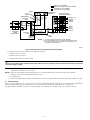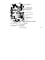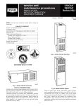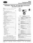
1
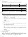
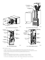
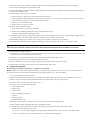
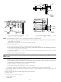
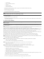
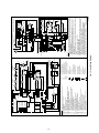
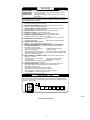
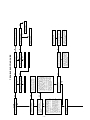
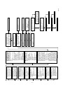
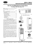
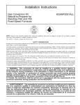
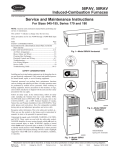
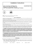
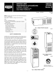
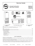
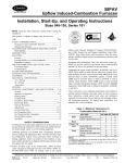
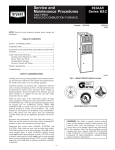
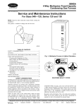
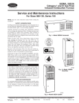
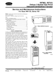
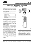
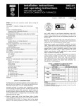
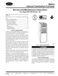
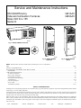
Service and Maintenance Instructions
HSI Mid-Efficiency
Induced-Combustion Furnaces
Sizes 045 thru 155
Series E
GB1AAV
GB3AAV
A94087
Fig. 1—Model GB3AAV Horizontal
CANADIAN GAS ASSOCIATION
®
ama
A PP R O VED
R
A94086
Fig. 2—Model GB3AAV
Downflow
A94085
Fig. 3—Model GB1AAV
Upflow
NOTE: Read the entire instruction manual before performing any service or maintenance.
Index
Page
SAFETY CONSIDERATIONS .................................................................................................................................................................................1-2
ELECTROSTATIC DISCHARGE (ESD) PRECAUTIONS
PROCEDURE...........................................................................................................................................................................................................2
CARE AND MAINTENANCE .................................................................................................................................................................................2-8
Air Filter Arrangement .........................................................................................................................................................................................2-3
Blower Motor and Wheel .....................................................................................................................................................................................3-5
Cleaning Heat Exchanger .....................................................................................................................................................................................5-7
Electrical Controls and Wiring.............................................................................................................................................................................7-8
Troubleshooting...................................................................................................................................................................................................8-13
Unit Wiring Diagram .............................................................................................................................................................................................10
Service Label ..........................................................................................................................................................................................................11
Troubleshooting Guide......................................................................................................................................................................................12-13
SAFETY CONSIDERATIONS
Installing and servicing heating equipment can be hazardous due to gas and electrical components. Only trained and qualified personnel should
install, repair, or service heating equipment.
Untrained personnel can perform basic maintenance functions such as cleaning and replacing air filters. All other operations must be performed
by trained service personnel. When working on heating equipment, observe precautions in the literature, on tags, and on labels attached to or
shipped with the unit and other safety precautions that may apply.
Follow all safety codes. In the United States, follow all safety codes including the National Fuel Gas Code (NFGC) NFPA No. 54-1992/ANSI
Z223.1-1992. In Canada, refer to the current edition of the National Standard of Canada CAN/CGA-B149.1- and .2-M91 Natural Gas and Propane
Installation Codes (NSCNGPIC). Wear safety glasses and work gloves. Have fire extinguisher available during start-up and adjustment procedures
and service calls.
Form:
SG-GB1A-06
Cancels:
SG-GB1A-05
Printed in U.S.A.
7-95
Catalog No.
92-33GB-1A14
Recognize safety information. This is the safety-alert symbol
alert to the potential for personal injury.
. When you see this symbol on the furnace and in instructions or manuals, be
Understand the signal words DANGER, WARNING, and CAUTION. These words are used with the safety-alert symbol. DANGER identifies the
most serious hazards which will result in severe personal injury or death. WARNING signifies a hazard which could result in personal injury or
death. CAUTION is used to identify unsafe practices which would result in minor personal injury or product and property damage. NOTE is used
to highlight suggestions which will result in enhanced installation, reliability, or operation.
WARNING: The ability to properly perform maintenance on this equipment requires certain expertise, mechanical
skills, tools, and equipment. If you do not possess these, do not attempt to perform any maintenance on this equipment other
than those procedures recommended in the User’s Manual. FAILURE TO FOLLOW THIS WARNING COULD RESULT IN
POSSIBLE DAMAGE TO THIS EQUIPMENT, SERIOUS PERSONAL INJURY, OR DEATH.
ELECTROSTATIC DISCHARGE (ESD) PRECAUTIONS PROCEDURE
CAUTION: Electrostatic discharge can affect electronic components. Take precautions during furnace installation and
servicing to protect the furnace electronic control. Precautions will prevent electrostatic discharges from personnel and
hand tools which are held during the procedure. These precautions will help to avoid exposing the control to electrostatic
discharge by putting the furnace, the control, and the person at the same electrostatic potential.
1. Disconnect all power to the furnace. DO NOT TOUCH THE CONTROL OR ANY WIRE CONNECTED TO THE CONTROL PRIOR
TO DISCHARGING YOUR BODY’S ELECTROSTATIC CHARGE TO GROUND.
2. Firmly touch a clean, unpainted, metal surface of the furnace chassis which is close to the control. Tools held in a person’s hand during
grounding will be satisfactorily discharged.
3. After touching the chassis you may proceed to service the control or connecting wires as long as you do nothing that recharges your body
with static electricity (for example; DO NOT move or shuffle your feet, DO NOT touch ungrounded objects, etc.).
4. If you touch ungrounded objects (recharge your body with static electricity), firmly touch furnace again before touching control or wires.
5. Use this procedure for installed and uninstalled (ungrounded) furnaces.
6. Before removing a new control from its container, discharge your body’s electrostatic charge to ground to protect the control from damage.
If the control is to be installed in a furnace, follow items 1 through 5 before bringing the control or yourself into contact with the furnace.
Put all used AND new controls into containers before touching ungrounded objects.
7. An ESD service kit (available from commercial sources) may also be used to prevent ESD damage.
CARE AND MAINTENANCE
For continuing high performance and to minimize possible equipment failure, it is essential that periodic maintenance be performed on this
equipment. Consult your local dealer as to the proper frequency of maintenance and the availability of a maintenance contract.
WARNING: Never store anything on, near, or in contact with the furnace, such as:
1. Spray or aerosol cans, rags, brooms, dust mops, vacuum cleaners, or other cleaning tools.
2. Soap powders, bleaches, waxes or other cleaning compounds, plastic or plastic containers, gasoline, kerosene, cigarette
lighter fluid, dry cleaning fluids, or other volatile fluids.
3. Paint thinners and other painting compounds, paper bags or other paper products.
A failure to follow this warning could result in corrosion of the heat exchanger, fire, personal injury, or death.
WARNING: Turn off the gas and electrical supplies to the unit before performing any maintenance or service. Follow
the operating instructions on label attached to furnace. A failure to follow this warning could result in personal injury.
The minimum maintenance that should be performed on this equipment is as follows:
1. Check and clean air filter each month or more frequently if required. Replace if torn.
2. Check blower motor and wheel for cleanliness each heating and cooling season. Clean and lubricate as necessary.
3. Check electrical connections for tightness and controls for proper operation each heating season. Service as necessary.
CAUTION: As with any mechanical equipment, personal injury can result from sharp metal edges, etc., therefore, be
careful when removing parts.
—2—
A.
Air Filter Arrangement
The air filter arrangement may vary depending on the application. Refer to Table 1 or 2 for filter size information.
Table 1—Filter Size Information for Downflow/Horizontal Furnaces (In.)
FURNACE
CASING WIDTH
14-3/16
17-1/2
21
24-1/2
FILTER QUANTITY
AND SIZE
(2) 14 X 20 X 1
(2) 14 X 20 X 1
(2) 16 X 20 X 1
(2) 16 X 20 X 1
FILTER
TYPE
Cleanable
Cleanable
Cleanable
Cleanable
Table 2—Filter Size Information for Upflow Furnaces (In.)
FURNACE
CASING WIDTH
14-3/16
17-1/2
21
24-1/2
FILTER QUANTITY AND SIZE
Side Return
Bottom Return
(1) 16 X 25 X 1*
(1) 14 X 25 X 1
(1) 16 X 25 X 1*
(1) 16 X 25 X 1
(1) 16 X 25 X 1
(1) 20 X 25 X 1*
(2) 16 X 25 X 1
(1) 24 X 29 X 1*
FILTER
TYPE
Cleanable
Cleanable
Cleanable
Cleanable
* Factory-provided with the furnace. Filter may be field modified as required by cutting to desired size.
WARNING: Never operate unit without a filter or with filter access door removed. A failure to follow this warning could
result in fire, personal injury, or death.
1. Downflow/Horizontal
Each furnace requires 2 filters which are installed in the return-air duct. (See Fig. 4 and 5.) To remove filters for cleaning or replacement,
proceed as follows:
a. Disconnect electrical power before removing blower access door.
b. Remove screw from front of door and remove blower access door.
c. Reach up behind top plate, tilt filters toward center of return-air plenum, remove filters, and clean as needed. Replace if torn.
d. Furnaces are equipped with permanent, washable filters. Clean filters with tap water. Spray water through filter in opposite direction of
airflow.
e. Rinse and let dry. Oiling or coating of filters is not recommended or required.
f. Reinstall filters.
g. Replace blower access door.
h. Restore electrical power to furnace.
2. Upflow
Each furnace requires 1 or 2 filters which are installed in the blower compartment. (See Fig. 6.) To remove filters for cleaning or
replacement, proceed as follows:
a. Disconnect electrical power before removing access doors.
b. Remove blower and control access doors.
c. Release filter retainer from clip at front of furnace casing. (See Fig. 6.) For side return, clips may be used on either or both sides of the
furnace.
d. Slide filter(s) out.
e. Furnaces are equipped with permanent, washable filters. Clean filters with tap water. Spray water through filter in opposite direction of
airflow.
f. Rinse and let dry. Oiling or coating of filter is not recommended or required.
g. Reinstall filter(s).
h. Replace blower and control access doors.
i. Restore electrical power to furnace.
B. Blower Motor and Wheel
For long life, economy, and high efficiency, clean accumulated dirt and grease from the blower wheel and motor annually.
The following steps should be performed by a qualified service technician.
Some motors have prelubricated sealed bearings and require no lubrication. These motors can be identified by the absence of oil ports on each
end of the motor. For those motors with oil ports, lubricate motor every 5 years if motor is used on intermittent operation (thermostat FAN switch
in AUTO position), or every 2 years if motor is in continuous operation (thermostat FAN switch in ON position).
NOTE: Remember to disconnect the electrical supply before removing access doors.
—3—
AIRFLOW
INSTALLATION
POSITION
OF FILTERS
RETURN-AIR
PLENUM
AIRFLOW
ACCESS DOOR
A94307
A88486
Fig. 4—Horizontal Filter Arrangement
Fig. 5—Downflow Filter Arrangement
VENT PIPE
ENCLOSURE
DRAFT
SAFEGUARD
SWITCH
MOUNTING
SCREWS
RELIEF
BOX
AUXILIARY
LIMIT
SWITCH
(WHEN USED)
FLUE
COLLECTOR
BOX
CONTROL
BOARD
MOUNTING
SCREWS
MANUAL
RESET LIMIT
SWITCH
RELIEF
BOX
FILTER
RETAINER
CONTROL
BOARD
DRAFT
SAFEGUARD
SWITCH
MANUAL
RESET LIMIT
SWITCHES
WASHABLE
FILTER
A92063
A92064
Fig. 6—Model GB1AAV Upflow
Fig. 7—Model GB3AAV Downflow
Clean and lubricate as follows:
1. Remove screw from blower access door (downflow/horizontal furnace only) and remove blower access door.
2. Remove vent pipe enclosure (downflow/horizontal furnace only) and disconnect short piece of vent pipe from relief box.
3. Disconnect wires from auxiliary limit on blower housing (downflow/horizontal furnace only).
4. Remove control.
5. Disconnect electrical leads from control. (See Fig. 6 or 7.) Note location of wires for reassembly.
6. Remove screws holding blower assembly to blower deck and slide blower assembly out of furnace.
7. Loosen screw in strap holding motor capacitor to blower housing and slide capacitor out from under strap.
—4—
8. Mark blower wheel, motor, and motor support in relation to blower housing before disassembly to ensure proper reassembly.
9. Loosen setscrew holding blower wheel on motor shaft.
10. Remove bolts holding motor mount to blower housing and slide motor and mount out of housing. Disconnect ground wire attached to blower
housing before removing motor.
11. Lubricate motor (when oil ports are provided).
a. Remove dust caps or plugs from oil ports located at each end of motor.
b. Use a good grade of SAE 20 nondetergent motor oil and put 1 teaspoon, 5 cc, 3/16 oz, or 16 to 25 drops in each oil port. Do not over-oil.
c. Allow time for total quantity of oil to be absorbed by each bearing.
d. Wipe excess oil from motor housing.
e. Replace dust caps or plugs on oil ports.
12. Remove blower wheel from housing.
a. Mark cutoff location to ensure proper reassembly.
b. Remove screws holding cutoff plate and remove cutoff plate from housing.
c. Lift blower wheel from housing through opening.
13. Clean blower wheel and motor using a vacuum cleaner with soft brush attachment. Do not remove or disturb balance weights (clips) on
blower wheel blades. The blower wheel should not be dropped or bent as balance will be affected.
14. Reinstall blower wheel by reversing items 12 a through c. Be sure wheel is positioned for proper rotation.
15. Reassemble motor and blower by reversing items 5 through 10. If motor has ground wire, be sure it is connected as before.
CAUTION: Be sure the motor is properly positioned in the blower housing. The motor oil ports must be at a minimum
of 45° above the horizontal centerline of the motor after the blower assembly has been reinstalled in the furnace.
16. Reinstall blower assembly in furnace.
17. Reinstall control. Connect blower electrical leads to control. Please note that the common wire connection is 3/16 in. and all other wire
connections are 1/4 in. for assembly. DO NOT FORCE.
18. Reconnect wires to auxiliary limit switch on blower housing (downflow/horizontal furnace only).
19. Reinstall vent pipe and enclosure (downflow/horizontal furnace only).
20. Turn on electrical power and check for proper rotation and speed changes between heating and cooling.
21. Replace blower access door. Secure with screw (downflow/horizontal furnace only).
C. Cleaning Heat Exchanger
The following steps should be performed by a qualified service technician.
NOTE: Deposits of soot and carbon indicate the existence of a problem which needs to be corrected. Take action to correct the problem.
If it becomes necessary to clean the heat exchanger because of carbon deposits, soot, etc., proceed as follows:
1. Turn off gas and electrical power to furnace.
2. Remove screw from front of blower access door (downflow/horizontal furnace only) and remove control and blower access doors.
3. Remove vent pipe enclosure (downflow/horizontal furnace only) and disconnect vent pipe from relief box.
4. Remove 2 screws that secure relief box. (See Fig. 6 or 7.)
5. Disconnect wires to the following components.
a. Draft safeguard switch
b. Inducer motor
c. Pressure switch
d. Limit overtemperature switch(es)
e. Gas valve
f. Hot surface ignitor
g. Flame-sensing electrode
6. Remove 8 screws that secure flue collector box to center panel. Be careful not to damage sealant.
7. Remove complete inducer assembly from furnace, exposing flue openings.
8. Clean cells using field-provided small wire brush, steel spring cable, reversible electric drill, and vacuum cleaner.
a. Assemble wire brush and steel spring cable.
(1.) Use 48 in. of 1/4-in. diameter high-grade steel spring cable (commonly known as drain clean-out or Roto-Rooter cable).
(2.) Use 1/4-in. diameter wire brush (commonly known as 25-caliber rifle cleaning brush).
—5—
11 32"
13 32"
BURNER
CELL
PANEL
HOT
SURFACE
IGNITOR
ASSEMBLY
C
L
7 8"
IGNITOR
C
L
BURNER
IGNITOR
ASSEMBLY
A91252
A93347
Fig. 8—Cleaning Heat Exchanger Cell
Fig. 9—Position of Ignitor to Burner
NOTE: The materials needed in items (1.) and (2.) can usually be purchased at local hardware stores.
(3.) Insert twisted wire end of brush into end of steel spring cable, and crimp tight with crimping tool or strike with ball-peen hammer.
TIGHTNESS is very important.
(4.) Remove metal screw fitting from wire brush to allow insertion into cable.
b. Clean each heat exchanger cell.
(1.) Attach variable-speed, reversible drill to end of steel spring cable (end opposite brush).
(2.) Insert brush end of cable into upper opening of cell and slowly rotate with drill. DO NOT force cable. Gradually insert at least 36
in. of cable into 2 upper passes of cell. (See Fig. 8.)
(3.) Work cable in and out of cell 3 or 4 times to obtain sufficient cleaning. DO NOT pull cable with great force. Reverse drill and
gradually work cable out.
(4.) Remove burner assembly and cell inlet plates.
CAUTION: Be very careful when removing the burner assembly to avoid breaking the ignitor. See Fig. 9 for the correct
ignitor location.
(5.) Replace screws in center panel and cells before cleaning.
(6.) Insert brush end of cable in lower opening of cell, and proceed to clean 2 lower passes of cell in same manner as 2 upper passes.
(7.) Repeat foregoing procedures until each cell in furnace has been cleaned.
(8.) Remove residue from each cell using vacuum cleaner.
(9.) Clean burner assembly using vacuum cleaner with soft brush attachment.
(10.) Reinstall cell inlet plates and burner assembly. Care must be exercised to center the burners in the cell openings.
9. After cleaning flue openings, check sealant on flue collector to ensure that it has not been damaged. If new sealant is needed, contact your
dealer or distributor.
10. Clean and replace flue collector assembly, making sure all 8 screws are secure.
11. Reinstall relief box.
12. Reconnect wires to the following components.
a. Draft safeguard switch
b. Inducer motor
—6—
c. Pressure switch
d. Limit overtemperature switch(es)
e. Gas valve
f. Hot surface ignitor
g. Flame-sensing electrode
13. Reconnect vent pipe to relief box. Replace vent pipe enclosure (downflow/horizontal furnace only).
14. Replace blower access door only.
15. Turn on electrical power and gas.
16. Set thermostat and check furnace for proper operation.
WARNING: Never use a match or other open flame to check for gas leaks. Use a soap-and-water solution. A failure to
follow this warning could result in fire, personal injury, or death.
17. Check for gas leaks.
18. Replace control access door on upflow furnace.
19. On downflow/horizontal furnaces, remove blower access door, replace control access door first, then replace blower access door and secure
with screw in front of door.
D.
Electrical Controls and Wiring
CAUTION: There may be more than 1 electrical supply to the unit. Check accessories and cooling unit for additional
electrical supplies.
The electrical ground and polarity for 115-v wiring must be maintained properly. Refer to Fig. 10 for field wiring information and to Fig. 12 for
unit wiring information.
NOTE: If the polarity is not correct, the STATUS LED on the control center will flash rapidly and prevent the furnace from operating. The control
system also requires an earth ground for proper operation of the control board and flame-sensing electrode.
The 24-v circuit contains an automotive-type, 3-amp fuse located on the control board. (See Fig. 11.) Any direct shorts of the 24-v wiring during
installation, service, or maintenance will cause this fuse to blow. If fuse replacement is required, use ONLY a fuse of identical size.
With power to the unit disconnected, check all electrical connections for tightness. Tighten all screws on electrical connections. If any smoky or
burned connections are found, disassemble the connection, clean all parts, strip wire, and reassemble properly and securely.
Reconnect electrical power to the unit and observe unit through 1 complete operating cycle. Electrical controls are difficult to check without proper
instrumentation; if there are any discrepancies in the operating cycle, contact your dealer and request service.
For an explanation of fault codes, refer to service label located on blower access door or Fig. 13, and the troubleshooting guide.
The control center stores 1 fault code (the last fault to occur) for a period of 48 hrs or until the 115- or 24-v power is interrupted.
NOTE: Removing blower access door will open blower access door switch and terminate 115-v power to control center, and fault code will be
erased. Look into blower access door sight glass for current LED status.
1. To retrieve fault code, proceed with the following:
NOTE: NO thermostat signal may be present at control center, and all blower time delay off periods must be completed.
a. Leave 115-v power to furnace turned on.
b. Look into blower access door sight glass for current LED status.
NOTE: Leave blower access panel installed to maintain power to control center to view current LED status.
c. Remove control access door.
d. BRIEFLY remove either wire from the main limit switch until LED goes out, then reconnect it.
NOTE: If wire to main limit is disconnected longer than 4 sec, main blower starts, and retrieval request is ignored.
2. When above items have been completed, the following will occur:
a. LED flashes a fault code 4 times. Record this fault code for further troubleshooting.
b. Inducer motor operates for 10 sec, then turns off.
c. Hot surface ignitor is energized for 15 sec, then de-energized.
d. Main blower operates at cooling speed for 10 sec, then turns off.
e. Main blower operates at heating speed for 10 sec, then turns off.
Items a through e above will assist in furnace troubleshooting since all components are functionally operated except the gas valve. This
procedure is also referred to as "Component Test."
3. Operate furnace through 1 heat cycle to test for proper operation and check LED status.
4. If furnace is operating properly and LED indicates proper operation, replace control access door.
—7—
FIELD 24-VOLT WIRING
FIELD 115-, 208/230-, 460-VOLT WIRING
FACTORY 24-VOLT WIRING
FACTORY 115-VOLT WIRING
NOTE 2
W
FIVE
WIRE
C
R
G
Y
THERMOSTAT
TERMINALS
FIELD-SUPPLIED
FUSED DISCONNECT
THREE-WIRE
HEATINGONLY
BLK
BLK
W
WHT
WHT
R
GND
GND
115-VOLT FIELD- AUXILIARY
J-BOX
SUPPLIED
CONTROL
FUSED
BOX
DISCONNECT
208/230- OR
460-VOLT
THREE
PHASE
G
C
NOTE 1
Y
24-VOLT
TERMINAL
BLOCK
FURNACE
GND
208/230VOLT
SINGLE
PHASE
CONDENSING
UNIT
TWO
WIRE
NOTES: 1. Connect Y-terminal as shown for proper operation.
2. Some thermostats require a "C" terminal connection as shown.
3. If any of the original wire, as supplied, must be replaced, use
same type or equivalent wire.
A95241
Fig. 10—Heating and Cooling Application Wiring Diagram
5. Component Test can also be initiated by performing the following:
a. Remove control access door.
b. Remove blower access door.
c. Manually close blower access door switch.
WARNING: Blower access door switch opens 115-v power to control center. No component operation can occur.
Caution must be taken when manually closing this switch for service purposes. Failure to follow this warning could result
in personal injury or death.
d. BRIEFLY short (jumper) TEST, 1/4-in. quick-connect terminal on control center (adjacent to LED diagnostic light), and Com terminal
on thermostat connection block. (See Fig. 11.)
NOTE: If TEST to Com terminals are jumpered longer than 2 sec, LED will flash rapidly, and retrieval request will be ignored.
e. Component Test will function as described in item 2 above.
f. Check LED status.
g. If LED status indicates proper operation, release blower access door switch, replace blower access door, and replace control access door.
E. Troubleshooting
Refer to the service label. (See Fig. 13.) Pages 10 and 11 contain a troubleshooting guide. This guide can be a useful tool in isolating furnace
operation problems. Beginning with the word "Start," answer each question and follow the appropriate arrow to the next item.
The guide will help to identify the problem or failed component. After replacing any component, verify correct operation sequence.
—8—
24V
COM W Y R G
TEST/TWIN
HUM
24-V THERMOSTAT
TERMINALS
HUMIDIFIER TERMINAL
(24-VAC 0.5 AMP MAX)
LED OPERATION &
DIAGNOSTIC LIGHT
HARNESS CONNECTOR
SEC-1
24-V TRANSFORMER SEC-2
3-AMP FUSE
SPARE-1
COOL
HEAT
BLOWER SPEED
SELECTION TERMINALS
SPARE-2
EAC-1
EAC-ELECTRONIC AIR CLEANER
TERMINALS (115-VAC 1.5 AMP MAX)
115-VAC (L1)
POWER SUPPLY
HOT SURFACE
IGNITOR CONNECTOR
EAC-2
115-VAC (L2) NEUTRAL
CONNECTION
INDUCER MOTOR
CONNECTOR
A95086
Fig. 11—Control Board
—9—
—10—
GV
GVR
HI/LO
HSI
HSIR
HUM
IDM
IDR
ILK
JB
LED
LGPS
LS
OL
PCB
ALS
BLWR
BLWM
CAP
CPU
DSS
EAC-1
EAC-2
FRS
FSE
FU1
FU2
HSI
2
PL5
1
2
PL3
1
2
3
BLK
WHT
PR2
L2
EAC-2
C OM
IDM
HEAT SPARE-2
EAC-1
COOL SPARE-1
24 VAC-3A
FUSE
ORN
WHT (COM)
RED (LO)
BLU (MED LO)
NOTE #8
YEL (MED HI)
BLK (HI)
ILK
BLK
BLU
NOTE #6
(WHEN USED)
LGPS
JB
BRN
NOTE #5
2-C
GRN
WHT
BLK
FU2
L1
L1
TEST/TWIN
ILK
FU1
IDR
HSIR
HSIR
HI/LO
IDR
CPU
BLWR
GVR-2
SEC-1
TRAN
PR1
EAC-2
EAC-1
NOTE #7
BLWR
2
1
HI/LO
PR2
PL5
GVR-1
GVR
SEC-2
24VAC
115VAC
PL2
2
1
1
9
6
5
8
2
3
4
1
7
2
3
HSI
OL
1-M
3-P
NOT USED
BLWM
START
IDM
CAP
NOTE #6
FSE
NOTE #5
2-C
ALS
(WHEN USED)
NOTE #12
GV
PRS
LS
FRS2
(WHEN USED)
LGPS (WHEN USED)
DSS
NOT USED
PL1
FRS1
NOT USED
PL3
LO
MED LO
MED HI
HI
SPARE-2
NOTE #8
COOL
COM
COM
SPARE-1
HEAT
EQUIPMENT GROUND
SCHEMATIC DIAGRAM
TO 115VAC FIELD DISCONNECT
(NATURAL GAS & PROPANE)
NOTE #4
NEUTRAL
L2
A95285
1. IF ANY OF THE ORIGINAL EQUIPMENT WIRE IS REPLACED USE WIRE RATED FOR 105°C.
2. INDUCER (IDM) AND BLOWER (BLWM) MOTORS CONTAIN INTERNAL AUTO-RESET THERMAL
OVERLOAD SWITCHES (OL).
3. BLOWER MOTOR SPEED SELECTIONS ARE FOR AVERAGE CONDITIONS, SEE INSTALLATION
INSTRUCTIONS FOR DETAILS ON OPTIMUM SPEED SELECTION.
4. USE ONLY COPPER WIRE BETWEEN THE DISCONNECT SWITCH AND THE FURNACE
JUNCTION BOX (JB).
5. THIS WIRE MUST BE CONNECTED TO FURNACE SHEETMETAL FOR CONTROL TO DETECT
FLAME.
6. FACTORY CONNECTED WHEN LGPS NOT USED.
7. REPLACE ONLY WITH A 3 AMP FUSE.
8. YELLOW LEAD NOT ON ALL MOTORS.
9. BLOWER-ON DELAY, GAS HEATING 45 SECONDS, COOLING OR HEAT PUMP 2 SECONDS.
10. BLOWER-OFF DELAY, GAS HEATING 90, 135, 180 OR 225 SECONDS, COOLING OR HEAT
PUMP 90 SECONDS. (135 SECONDS ONLY ON SOME MODELS)
11. IGNITION-LOCKOUT WILL OCCUR AFTER FOUR CONSECUTIVE UNSUCCESSFUL
TRIALS-FOR-IGNITION. CONTROL WILL AUTO-RESET AFTER THREE HOURS.
12. WHEN USED AUXILIARY LIMIT SWITCH (ALS) IS ON DOWNFLOW MODELS ONLY.
13. SOME MODELS MAY HAVE SPADE QUICK CONNECT TERMINALS.
322858-101 REV. A
NOTES:
COM
G
Y
W
R
HUM
NOTE #13
Fig. 12—Unit Wiring Diagram
PLUG RECEPTACLE
FIELD SPLICE
EQUIPMENT GROUND
FIELD GROUND
FIELD WIRING TERMINAL
CONDUCTOR ON PCB
FIELD WIRING (24VAC)
FIELD WIRING (115VAC)
FACTORY WIRING (24VAC)
FACTORY WIRING (115VAC)
PCB TERMINAL
UNMARKED TERMINAL
JUNCTION
NEUTRAL
L1
FUSED DISCONNECT
SWITCH (WHEN REQ’D)
NOTE #4
CAP
WHT (COM)
GRN
WHT
BLK
GRN
FRS1
GV
3-P
YEL
9-CIRCUIT CONNECTOR
2-CIRCUIT PCB CONNECTOR
3-CIRCUIT IDM CONNECTOR
2-CIRCUIT HSI/PCB CONNECTOR
PRESSURE SWITCH, SPST-(N.O.)
COMPONENT TEST & TWIN TERMINAL
TRANSFORMER-115VAC/24VAC
GRN
BLWM
BRN
FSE
(WHEN USED)
FRS2
1-M
START
PRS
PL1
PL2
PL3
PL5
PRS
TEST/TWIN
TRAN
WHT
OL
RED
BLU
RED
LS
RED
(WHEN USED)
NOTE #12
ALS
WHT
RED
DSS
AUXILIARY LIMIT SWITCH, OVERTEMP. -MANUAL RESET, SPST-(N.C.)
BLOWER MOTOR RELAY, SPST-(N.O.)
BLOWER MOTOR
CAPACITOR
MICROPROCESSOR AND CIRCUITRY
DRAFT SAFEGUARD SWITCH
ELECTRONIC AIR CLEANER CONNECTION (115 VAC 1.5 AMP MAX.)
ELECTRONIC AIR CLEANER CONNECTION (COMMON)
FLAME ROLLOUT SW. -MANUAL RESET, SPST-(N.C.)
FLAME PROVING ELECTRODE
FUSE, 3 AMP, AUTOMOTIVE BLADE TYPE, FACTORY INSTALLED
FUSE OR CIRCUIT BREAKER CURRENT INTERRUPT DEVICE
(FIELD INSTALLED & SUPPLIED)
GAS VALVE-REDUNDANT OPERATORS
GAS VALVE RELAY, DPST-(N.O.)
BLOWER MOTOR SPEED CHANGE RELAY, SPDT
HOT SURFACE IGNITOR (115 VAC)
HOT SURFACE IGNITOR RELAY, SPST-(N.O.)
24VAC HUMIDIFIER CONNECTION (.5 AMP. MAX.)
INDUCED DRAFT MOTOR
INDUCED DRAFT RELAY, SPST-(N.O.)
BLOWER ACCESS PANEL INTERLOCK SWITCH, SPST-(N.O.)
JUNCTION BOX
LIGHT-EMITTING DIODE FOR STATUS CODES
LOW GAS PRESSURE SWITCH, SPST-(N.O.)
LIMIT SWITCH, AUTO RESET, SPST(N.C.)
AUTO-RESET INTERNAL MOTOR OVERLOAD TEMP. SW.
PRINTED CIRCUIT BOARD
LEGEND
1
PL2
BLOWER
SPEED
SELECT
FU1
LED
G
R
Y
W
C OM
HUM
SEC-2
6 5 4
9 8 7
3 2 1
SEC-1
PL1
TEST/TWIN
HI/LO
RELAY
BLWR
GVR
225 SEC
180 SEC
135 SEC
IDR
BLK
120 VAC
L1 PR1
BLK
90 SEC
BLOWER OFF DELAY
SELECTION CHART
HSIR
BLK
SEE NOTE #10
(NOT ON ALL MODELS)
WHT
SW2
BLOWER
OFF
DELAY
SW1
1.5 AMP
PCB
WHT
TRAN
SERVICE
STATUS
LED CODE
CONTINUOUS OFF CONTINUOUS ON RAPID FLASHING -
Check for 115VAC at L1 and L2, and 24VAC at SEC-1 and SEC-2.
Control has 24V power.
Line voltage (115V) polarity reversed. If twinned, refer to twinning
kit instructions.
EACH OF THE FOLLOWING STATUS CODES IS A TWO DIGIT NUMBER WITH THE FIRST
DIGIT DETERMINED BY THE NUMBER OF SHORT FLASHES AND THE SECOND DIGIT BY
THE NUMBER OF LONG FLASHES.
11 NO PREVIOUS CODE - Stored status codes are erased when power (115V or 24V) to control is
interrupted or 48 hours after each fault is cleared.
12 BLOWER ON AFTER POWER UP (115V or 24V) - Blower runs for 90 seconds, if unit
is powered up during a call for heat (R-W closed).
13 LIMIT OR FLAME ROLL-OUT SWITCH LOCKOUT - Auto reset after three hours. Flame
roll-out switch requires manual reset. Refer to #33.
14 IGNITION LOCKOUT - Control will auto-reset after three hours. Refer to #34.
21 GAS HEATING LOCKOUT - Control will NOT auto reset.
Check for: - Stuck gas valve relay on control or miswire to gas valve circuit.
22 ABNORMAL FLAME-PROVING SIGNAL - Flame is proved while gas valve is
de-energized. Inducer will run until fault is cleared. Check for:
- Stuck-open gas valve or leaky gas valve.
23 PRESSURE SWITCH DID NOT OPEN Check for:
- Obstructed pressure tubing.
- Defective pressure switch (stuck closed).
24 SECONDARY VOLTAGE FUSE IS OPEN
Check for: - Short circuit in secondary voltage (24V) wiring.
31 PRESSURE, DRAFT SAFEGUARD, OR AUXILIARY-LIMIT (when used) SWITCH DID
NOT CLOSE OR REOPENED - If open longer than five minutes, inducer shuts off for
15 minutes before retry. Check for:
- Proper vent sizing and condensate pitch.
- Inadequate Combustion air supply.
- Vent restriction or high winds.
- Low inducer voltage.
- Defective inducer motor or start capacitor.
- Disconnected or obstructed pressure tubing.
- Defective pressure switch or connections. If it opens after trial for ignition period, blower will
come on for 90 second recycle delay.
33 LIMIT OR FLAME ROLL-OUT SWITCH IS OPEN - If open longer than three minutes, code
changes to #13. Check for:
- Defective blower motor or start capacitor.
- Dirty filter or restricted duct system.
- Loose blower wheel.
- Defective switch or connections.
- Inadequate Combustion air supply Flame Roll-out Switch only.
- Open Flame Roll-out and switch, manual reset.
34 IGNITION PROVING FAILURE - Control will try three more times before a lockout #14
occurs. If flame signal lost after trial for ignition period, blower will come on for
90 second recycle delay. Check for:
- Oxide buildup on flame sensor (clean with fine sandpaper).
- Proper flame sense microamps (.5 microamps D.C. minimum).
- Gas valve turned off. - Manual shut-off valve. - Low inlet gas pressure.
- Green wire MUST be connected to furnace sheet metal.
- Inadequate flame carryover or rough ignition.
COMPONENT TEST
To initiate the component test sequence,shut OFF the room thermostat or disconnect the "R"
thermostat lead. Briefly short the TEST terminal to the ’C’ terminal. Status LED will flash code and
then turn on the inducer motor, hot surface igniter, blower motor-heat speed, and blower motor-cool
speed for 10-15 seconds each.
3
9
6
TEST
4
1
7
STATUS
2
5
8
HUM
C
W
Y
R
G
320615-102 REV. C
A93297
Fig. 13—Service Label
—11—
—12—
START
Go to section with status code
determined.
Determine status code. The
status code is a 2 digit number
with the first digit determined by
the number of short flashes and
the second digit by the number of
long flashes.
Once status code is determined,
the control will go through a brief
component test sequence by
sequentially operating the inducer
motor, HSI, blower motor relay
heat speed, and cool speed for
approximately 10-15 sec, then go
off.
YES
Is red LED status light blinking
ON/OFF slowly with a
combination of short and long
flashes?
NO
Is red LED status light blinking
rapidly without a pause?
YES
Is red LED status light on?
NO
YES
NO
YES
Was there a previous fault code
other than No. 11?
Check for previous fault by
momentarily shorting the TEST
terminal and the C terminal until
the LED goes out. LED will flash
the status code of any previous
fault or the code No. 11 (1 short
and 1 long flash) if no previous
fault. After the control repeats the
code 3 times, it will sequentially
operate the inducer motor, HSI,
blower motor relay heat speed,
and cool speed for approximately
10-15 sec, then go off.
Check for correct line voltage
polarity. If units are twinned,
check for proper low-voltage
(24v) transformer phasing.
Replace control center.
YES
Is there 24v at SEC-1 and SEC-2?
YES
Is there 115v at L1 and L2?
NO
NO
NO
Run system through a heating or
cooling cycle to check operation.
Status codes are erased after 48
hrs or whenever power (115v
or 24v) is interrupted.
YES
Does control respond to W, Y,
or G 24-vac thermostat signals?
Replace transformer.
Replace door switch.
YES
Is there 115v going to switch?
YES
Is door switch closed?
TROUBLE SHOOTING GUIDE
NO
NO
NO
Replace control if it does not
respond to 24-vac signal at W, Y,
or G screw terminals.
YES
Is 24 vac present at W, Y, or G
terminals on the control?
NO
Check room thermostat or
interconnecting cable.
NO
Close circuit breaker and
go back to start.
Check for continuity in wire from circuit
breaker to furnace.
YES
Is circuit breaker closed?
Close door switch and go to start.
—13—
24 LOW-VOLTAGE FUSE IS
OPEN - Check for:
• Short in low-voltage wiring
including thermostat leads
shorting to ductwork or
furnace cabinet. Disconnect
thermostat leads to isolate
short circuit.
23 PRESSURE SWITCH WILL
NOT OPEN - Check for:
• Disconnected or obstructed
pressure tubing.
• Defective pressure switch.
22 ABNORMAL FLAME PROVING
SIGNAL - Flame was sensed
while gas valve was
de-energized. Inducer will run
until fault is cleared.
Check for:
• Stuck open gas valve solenoid
or leak.
• Defective control board.
21 GAS HEATING LOCKOUT Turn off power and wait 5
minutes to retry.
Check for:
• Stuck closed gas valve relay
on control.
• Miswire or short to gas valve
wire.
14 IGNITION LOCKOUT - System
failed to ignite gas and prove
flame in 4 attempts. Control will
auto-reset in 3 hrs.
See No. 34
13 LIMIT OR FLAME ROLLOUT
SWITCH LOCKOUT - Limit
switch was open longer than
3 minutes. Auto-reset will occur
after 3 hrs. Flame rollout switch
requires manual reset.
See No. 33
12 BLOWER ON AFTER POWER
UP (115V OR 24V) - Normal
operation. Blower will run for 90
sec when furnace power is
interrupted during a call for heat
and R-W closes.
11 NO PREVIOUS FAULT - Faults
are erased after 48 hrs or
whenever power (115V or 24V)
is interrupted. Run system
through a heating or cooling
cycle to recheck system.
YES
34 IGNITION PROVING FAILURE If flame is not sensed during the
trial for ignition period, the control
will repeat the ignition sequence
3 more times before going into
lockout, No. 14.
If flame signal is lost after trial for
ignition period, blower will come
on for 90 sec recycle delay.
Check for the following items first
before proceding to the next step.
• Gas valve turned off.
• Manual shut-off valve.
• Green wire must be connected
NO
to furnace sheet metal.
To determine whether the
problem is in the gas valve,
igniter, or flame sensor, the
system can be operated in the
component test mode to check
out the ignitor. First, remove the
R thermostat connection from the
control board and initiate the
component test sequence. Does
the ignitor glow orange/white hot
by the end of the 17 sec warm-up
period?
33 LIMIT OR FLAME ROLLOUT
SWITCH IS OPEN - If limit
switch is open longer than 3
minutes, code changes to No. 13.
Check for:
• Blower motor failure.
• Motor start capacitor.
• Open flame rollout switch,
manual reset.
• Inadequate combustion air
supply (flame rollout
switch only).
• Dirty filter.
• Defective limit switch or
connections.
• Loose blower wheel.
31 PRESSURE, DRAFT
SAFEGUARD (WHEN USED),
OR AUXILIARY LIMIT (WHEN
USED) SWITCH WILL NOT
CLOSE OR REOPEN - If open
longer than 5 minutes, inducer
shuts off for 15 minutes before
retry.
Check for:
• Proper vent sizing or pitch or
sag.
• Vent restrictions or high winds.
• Defective inducer motor.
• Low-line voltage (115v).
• Motor start capacitor.
• Low inlet gas pressure.
• Defective pressure switch or
connections. If it opens after
trial for igniton period, blower
will come on for 90 sec
recycle delay.
• Inadequate combustion air
(for draft safeguard and
auxiliary limit switches only).
Allow blower to come on and repeat
test to check for intermittent
operation.
YES
Do main burners stay on?
YES
Do main burners ignite?
YES
Does gas valve open and allow gas
to flow?
YES
Reconnect the R thermostat lead
and set thermostat to call for heat.
Connect voltmeter across gas valve
connections. Does gas valve
receive 24v?
Check for continuity in the harness
and ignitor. Replace defective
component.
YES
Unplug ignitor harness from control
center and inititate another
component test sequence and check
for 115v between pins 1 and 2 on
the board. Was there 115v present
for the 17 sec period?
NO
NO
NO
NO
NO
Fixed.
NO
Replace control board.
Will main burner ignite and stay on?
YES
NO
Replace electrode.
Is current near typical value?
YES
NO
Check connections and retry. If
current is near typical value and
control will not stay on, replace
control board.
Clean flame sensor with fine
sandpaper and recheck current.
Current is nominally 4.0 to 6.0
microamps.
YES
Repeat call for heat and check flame
sensor current during trial for ignition
period. Is the dc microamperes
below 0.5?
Check for:
• Inadequate flame carryover on
rough ignition.
• Low inlet gas pressure.
Check that all gas valves are turned
on. Replace valve.
Check connections. If OK, replace
control board.
Replace control board.
A95303
SERVICE TRAINING
Packaged Service Training programs are an excellent way to increase your
knowledge of the equipment discussed in this manual, including:
• Unit Familiarization
• Maintenance
• Installation Overview
• Operating Sequence
A large selection of product, theory, and skills programs is available, using popular
video-based formats and materials. All include video and/or slides, plus companion
book.
Classroom Service Training plus "hands-on" the products in our labs can mean
increased confidence that really pays dividends in faster troubleshooting, fewer
callbacks. Course descriptions and schedules are in our catalog.
CALL FOR FREE CATALOG 1-800-962-9212
[ ] Packaged Service Training
[ ] Classroom Service Training
A94328
© 1995 CAC / BDP
P.O. Box 70, Indianapolis, IN 46206
sggb1a06
—14—
Book/Tab: 1/6a, 4/8a
Catalog No. 92-33GB-1A14