1
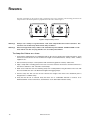
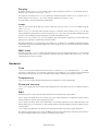
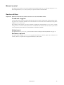
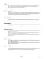
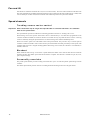
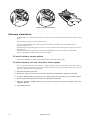
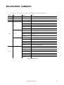
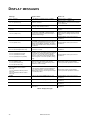
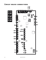
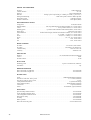
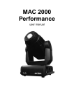
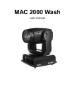
MAC 550 Profile
user manual
255
120°
120°
645
365
14°
636
30°
515
390
143
450
270°
270°
505
Figure 1: Dimensions in mm
© 2003 Martin Professional A/S, Denmark. All rights reserved. No part of this manual may be reproduced, in any form or by any
means, without permission in writing from Martin Professional A/S, Denmark. Printed in Denmark.
P/N 35000136, Rev. A
INTRODUCTION . . . . . . . . . . . . . . . . . . . . . . . . . . . . . . . . . . . . . . . . . . . . . . . . . . . . . . . . . . . . 4
Safety information . . . . . . . . . . . . . . . . . . . . . . . . . . . . . . . . . . . . . . . . . . . . . . . . . . . . . . . . . . . . . . . . . . . . . . 4
Included items . . . . . . . . . . . . . . . . . . . . . . . . . . . . . . . . . . . . . . . . . . . . . . . . . . . . . . . . . . . . . . . . . . . . . . . . . 5
Tilt lock . . . . . . . . . . . . . . . . . . . . . . . . . . . . . . . . . . . . . . . . . . . . . . . . . . . . . . . . . . . . . . . . . . . . . . . . . . . . . . 5
LAMP . . . . . . . . . . . . . . . . . . . . . . . . . . . . . . . . . . . . . . . . . . . . . . . . . . . . . . . . . . . . . . . . . . . 6
About the discharge lamp . . . . . . . . . . . . . . . . . . . . . . . . . . . . . . . . . . . . . . . . . . . . . . . . . . . . . . . . . . . . . . . . 6
Lamp replacement . . . . . . . . . . . . . . . . . . . . . . . . . . . . . . . . . . . . . . . . . . . . . . . . . . . . . . . . . . . . . . . . . . . . . 6
AC POWER . . . . . . . . . . . . . . . . . . . . . . . . . . . . . . . . . . . . . . . . . . . . . . . . . . . . . . . . . . . . . . . 8
Fuses . . . . . . . . . . . . . . . . . . . . . . . . . . . . . . . . . . . . . . . . . . . . . . . . . . . . . . . . . . . . . . . . . . . . . . . . . . . . . . . 8
Power supply adjustment . . . . . . . . . . . . . . . . . . . . . . . . . . . . . . . . . . . . . . . . . . . . . . . . . . . . . . . . . . . . . . . . 8
Power connection . . . . . . . . . . . . . . . . . . . . . . . . . . . . . . . . . . . . . . . . . . . . . . . . . . . . . . . . . . . . . . . . . . . . . . 8
DATA . . . . . . . . . . . . . . . . . . . . . . . . . . . . . . . . . . . . . . . . . . . . . . . . . . . . . . . . . . . . . . . . . . . 9
Connecting fixtures . . . . . . . . . . . . . . . . . . . . . . . . . . . . . . . . . . . . . . . . . . . . . . . . . . . . . . . . . . . . . . . . . . . . . 9
RIGGING. . . . . . . . . . . . . . . . . . . . . . . . . . . . . . . . . . . . . . . . . . . . . . . . . . . . . . . . . . . . . . . . 10
CONTROL PANEL . . . . . . . . . . . . . . . . . . . . . . . . . . . . . . . . . . . . . . . . . . . . . . . . . . . . . . . . . 11
Navigation . . . . . . . . . . . . . . . . . . . . . . . . . . . . . . . . . . . . . . . . . . . . . . . . . . . . . . . . . . . . . . . . . . . . . . . . . . . 11
DMX address and protocol . . . . . . . . . . . . . . . . . . . . . . . . . . . . . . . . . . . . . . . . . . . . . . . . . . . . . . . . . . . . . . 11
Tailoring performance . . . . . . . . . . . . . . . . . . . . . . . . . . . . . . . . . . . . . . . . . . . . . . . . . . . . . . . . . . . . . . . . . . 11
Readouts. . . . . . . . . . . . . . . . . . . . . . . . . . . . . . . . . . . . . . . . . . . . . . . . . . . . . . . . . . . . . . . . . . . . . . . . . . . . 12
Manual control. . . . . . . . . . . . . . . . . . . . . . . . . . . . . . . . . . . . . . . . . . . . . . . . . . . . . . . . . . . . . . . . . . . . . . . . 13
Service utilities . . . . . . . . . . . . . . . . . . . . . . . . . . . . . . . . . . . . . . . . . . . . . . . . . . . . . . . . . . . . . . . . . . . . . . . 13
EFFECTS . . . . . . . . . . . . . . . . . . . . . . . . . . . . . . . . . . . . . . . . . . . . . . . . . . . . . . . . . . . . . . . 14
Lamp power . . . . . . . . . . . . . . . . . . . . . . . . . . . . . . . . . . . . . . . . . . . . . . . . . . . . . . . . . . . . . . . . . . . . . . . . .
Fixture reset . . . . . . . . . . . . . . . . . . . . . . . . . . . . . . . . . . . . . . . . . . . . . . . . . . . . . . . . . . . . . . . . . . . . . . . . .
Dimming and strobe . . . . . . . . . . . . . . . . . . . . . . . . . . . . . . . . . . . . . . . . . . . . . . . . . . . . . . . . . . . . . . . . . . .
Color . . . . . . . . . . . . . . . . . . . . . . . . . . . . . . . . . . . . . . . . . . . . . . . . . . . . . . . . . . . . . . . . . . . . . . . . . . . . . . .
Rotating gobos . . . . . . . . . . . . . . . . . . . . . . . . . . . . . . . . . . . . . . . . . . . . . . . . . . . . . . . . . . . . . . . . . . . . . . .
Static gobos . . . . . . . . . . . . . . . . . . . . . . . . . . . . . . . . . . . . . . . . . . . . . . . . . . . . . . . . . . . . . . . . . . . . . . . . .
Gobo macros. . . . . . . . . . . . . . . . . . . . . . . . . . . . . . . . . . . . . . . . . . . . . . . . . . . . . . . . . . . . . . . . . . . . . . . . .
Gobo animation. . . . . . . . . . . . . . . . . . . . . . . . . . . . . . . . . . . . . . . . . . . . . . . . . . . . . . . . . . . . . . . . . . . . . . .
Prism and iris . . . . . . . . . . . . . . . . . . . . . . . . . . . . . . . . . . . . . . . . . . . . . . . . . . . . . . . . . . . . . . . . . . . . . . . .
Focus and zoom . . . . . . . . . . . . . . . . . . . . . . . . . . . . . . . . . . . . . . . . . . . . . . . . . . . . . . . . . . . . . . . . . . . . . .
Pan and tilt . . . . . . . . . . . . . . . . . . . . . . . . . . . . . . . . . . . . . . . . . . . . . . . . . . . . . . . . . . . . . . . . . . . . . . . . . .
Speed channels . . . . . . . . . . . . . . . . . . . . . . . . . . . . . . . . . . . . . . . . . . . . . . . . . . . . . . . . . . . . . . . . . . . . . .
14
14
14
15
15
15
15
15
15
15
16
16
OPTICAL CONFIGURATION . . . . . . . . . . . . . . . . . . . . . . . . . . . . . . . . . . . . . . . . . . . . . . . . . . . 17
Color wheels . . . . . . . . . . . . . . . . . . . . . . . . . . . . . . . . . . . . . . . . . . . . . . . . . . . . . . . . . . . . . . . . . . . . . . . . . 17
Gobos . . . . . . . . . . . . . . . . . . . . . . . . . . . . . . . . . . . . . . . . . . . . . . . . . . . . . . . . . . . . . . . . . . . . . . . . . . . . . . 18
Animation wheel . . . . . . . . . . . . . . . . . . . . . . . . . . . . . . . . . . . . . . . . . . . . . . . . . . . . . . . . . . . . . . . . . . . . . . 20
ROUTINE MAINTENANCE . . . . . . . . . . . . . . . . . . . . . . . . . . . . . . . . . . . . . . . . . . . . . . . . . . . . 22
Disassembly . . . . . . . . . . . . . . . . . . . . . . . . . . . . . . . . . . . . . . . . . . . . . . . . . . . . . . . . . . . . . . . . . . . . . . . . .
Cleaning . . . . . . . . . . . . . . . . . . . . . . . . . . . . . . . . . . . . . . . . . . . . . . . . . . . . . . . . . . . . . . . . . . . . . . . . . . . .
Lubrication. . . . . . . . . . . . . . . . . . . . . . . . . . . . . . . . . . . . . . . . . . . . . . . . . . . . . . . . . . . . . . . . . . . . . . . . . . .
Software installation . . . . . . . . . . . . . . . . . . . . . . . . . . . . . . . . . . . . . . . . . . . . . . . . . . . . . . . . . . . . . . . . . . .
22
23
23
24
DMX PROTOCOL . . . . . . . . . . . . . . . . . . . . . . . . . . . . . . . . . . . . . . . . . . . . . . . . . . . . . . . . . 25
CONTROL MENU . . . . . . . . . . . . . . . . . . . . . . . . . . . . . . . . . . . . . . . . . . . . . . . . . . . . . . . . . 31
ADJUSTMENT SUBMENU . . . . . . . . . . . . . . . . . . . . . . . . . . . . . . . . . . . . . . . . . . . . . . . . . . . . 34
DISPLAY MESSAGES . . . . . . . . . . . . . . . . . . . . . . . . . . . . . . . . . . . . . . . . . . . . . . . . . . . . . . . 35
TROUBLESHOOTING . . . . . . . . . . . . . . . . . . . . . . . . . . . . . . . . . . . . . . . . . . . . . . . . . . . . . . . 36
CIRCUIT BOARD CONNECTIONS . . . . . . . . . . . . . . . . . . . . . . . . . . . . . . . . . . . . . . . . . . . . . . . 37
SPECIFICATIONS . . . . . . . . . . . . . . . . . . . . . . . . . . . . . . . . . . . . . . . . . . . . . . . . . . . . . . . . . . 38
INTRODUCTION
Thank you for selecting the Martin MAC 550 Profile. This 400 watt moving head spotlight provides a full-range
mechanical dimmer/shutter, 16 color filters on two overlapping wheels, six rotating gobos with 16-bit position
indexing, nine static gobos, interchangeable gobo animation wheel, three-facet rotating prism, iris, variable focus and
zoom, 540° of pan, 246° of tilt, and an electronic “flicker-free” ballast.
For the latest updates of product documentation and software, please visit the Martin web site at www.martin.com.
Safety information
Warning!
This product is for professional use only. It is not for household use.
This product presents risks of lethal or severe injury due to fire and heat, electric shock, ultraviolet radiation, lamp
explosion, and falls. Read this manual before powering or installing the fixture, follow the safety precautions listed
below and observe all warnings in this manual and printed on the fixture. If you have questions about how to operate
the fixture safely, please contact your Martin dealer or call the Martin 24-hour service hot line at +45 70 200 201.
Protection from electric shock
• Disconnect the fixture from AC power before removing or installing the lamp, fuses, or any part, and when not in use.
• Always ground (earth) the fixture electrically.
• Use only a source of AC power that complies with local building and electrical codes and has both overload and
ground-fault protection.
• Do not expose the fixture to rain or moisture.
• Refer any service operation not described in this manual to a qualified technician.
Protection from UV radiation and lamp explosion
• Never operate the fixture with missing or damaged lenses and/or covers.
• When replacing the lamp, allow the fixture to cool for at least 15 minutes before opening the fixture or removing the
lamp. Protect your hands and eyes with gloves and safety glasses.
• Do not stare directly into the light. Never look at an exposed lamp while it is lit.
• Replace the lamp if it becomes defective or worn out, or before usage exceeds the maximum service life.
Protection from burns and fire
• Never attempt to bypass the thermostatic switch or fuses. Always replace defective fuses with ones of the specified
type and rating.
• Keep all combustible materials (for example fabric, wood, paper) at least 0.5 meters (20 inches) away from the fixture.
Keep flammable materials well away from the fixture.
• Do not illuminate surfaces within 1.0 meter (39 inches) of the fixture.
• Provide a minimum clearance of 0.1 meters (4 inches) around fans and air vents.
• Never place filters or other materials over the lens.
• The exterior of the fixture can get very hot. Allow the fixture to cool for at least 5 minutes before handling.
• Do not modify the fixture or install other than genuine Martin parts.
• Do not operate the fixture if the ambient temperature (Ta) exceeds 40° C (104° F).
Protection from injury due to falls
• When suspending the fixture, verify that the structure can hold at least 10 times the weight of all installed devices.
• Verify that all external covers and rigging hardware are securely fastened and use an approved means of secondary
attachment such as a safety cable.
• Block access below the work area whenever installing or removing the fixture.
4
MAC 550 Profile
Unpacking
The MAC 550 Profile is packaged in either a cardboard box or a two-unit flight case that is specifically designed to
protect the product during shipment. The following items are included:
•
•
•
•
•
OSRAM HTI 400/D3 lamp (installed)
this user manual
a 6.3 A fuse (installed) for use with 200 - 260 V power
a 10 A fuse for use with 90 -130 V power
2 clamp attachment brackets
Initial set-up
Before applying power to the fixture,
•
•
•
•
carefully review the safety information on page 4,
verify that the power supply is configured for the mains supply as described on page 8,
install a cord cap on the mains lead as described on page 8, and
unlock the tilt lock as described on page 22.
When powered up, check lamp alignment as described on page 7.
Introduction
5
LAMP
About the discharge lamp
The MAC 550 Profile is designed to use the OSRAM HTI 400
W/D3 lamp. This highly-efficient double-ended short-arc source
provides a color temperature of 7500K, a color rendering index
greater than 80, an average service life of 750 hours and hot
restrike.
Warning!
Installing any other lamp may create a safety
hazard or damage the fixture!
To reduce the risk of explosion, replace the lamp before usage
exceeds 125% of the average service life, i.e., before usage
exceeds 940 hours. To read lamp hours from the control panel,
please refer to “Readouts” on page 12.
Figure 1: Lamp access
For maximum service life, avoid turning off the lamp before it
has warmed up fully.
Lamp replacement
Important! Do not touch the quartz bulb with bare fingers.
Replacement lamps are available from your Martin dealer.
The clear quartz bulb must be clean and free of any oils from
your fingers. Clean the lamp with an alcohol wipe and polish it
with a dry cloth, particularly if you accidentally touch the bulb.
To repl ace t he lamp
1
Disconnect the fixture from power and allow it to cool
completely. Lock the head right-side up.
2
Release the 4 quarter-turn fasteners marked with arrows
on the rear plate. Pull the lamp assembly straight back as
far as it goes and let it rest in place.
3
6
Push down the retention spring on the right end of the
socket and push out the pin. You can use a screwdriver to
pry the lamp out of the socket as shown in Figure 2. Remove the lamp.
MAC 550 Profile
Figure 2: Lamp removal
4
With the nipple on the replacement lamp facing back as
shown in Figure 3, insert the left pin into the socket. Push
down on the right-hand spring and snap the pin into place.
5
Lift the lamp assembly so that lamp is level with the center
of the reflector. Push the assembly straight in until it seats,
making sure the lamp passes through the reflector opening.
6
Push and turn the 4 fasteners a quarter turn or so
clockwise to close the lamp access panel.
7
After installing a new lamp, reset the lamp hour and lamp
strike counters. See “Time” on page 12.
To align the lamp
Important! Align the lamp carefully. Too much hot-spot will
damage optical components.
1
Switch on the MAC 550 Profile and allow it to reset. Using
either a controller or the control module, turn on the lamp
and project an open white beam on a flat surface.
Figure 3: Lamp insertion
2
Center the hot spot vertically using the top Allen-head
adjustment screw in the center of the rear plate. (See
Figure 4.) If there is significant hot spot, turn the bottom
adjustment screw counterclockwise until the light is evenly
distributed. If the light is brighter around the edge than it is
in the center, or if light output is low, turn the bottom
adjustment screw clockwise until the light is bright and
evenly distributed.
Figure 4: Lamp adjustment screws
Lamp
7
AC
POWER
WARNING! For protection from electric shock, the fixture must be grounded (earthed). The AC mains
supply shall be fitted with a fuse or circuit breaker and ground-fault protection.
Important! Verify the power supply setting before applying power.
Fuses
The MAC 550 Profile comes with two main fuses:
• a 6.3 A fuse (installed) for use with AC supplies of 200 - 260 volts
• a 10 A fuse (packed with user manual) for use with AC supplies of 90 - 130 volts
Install the appropriate fuse in the holder beneath the power switch.
Power supply adjustment
The MAC 550 Profile can operate on 90-130 V and 200-260 V AC mains supplies. The voltage selection switch is set
at the factory for 200-260 V AC. For use with 90-130 V supplies, the fixture must be re configured as follows.
To conf igure t he power suppl y
1
Disconnect the fixture from AC power.
2
Remove the metal top cover from the front of the base, which is indicated by an arrow on the bottom.
3
Locate the voltage selection switch. For operation on 200 - 260 V AC supplies, move the switch to the
“230V” setting. For operation on 90 - 130 V AC supplies, move the switch the to “115V” setting.
4
Replace the base cover.
5
Remove the main fuse holder, which is located beneath the power switch. For operation on 200 - 260 V AC
supplies, install the 6.3 A fuse. For operation on 90 - 130 V AC supplies, install the 10 A fuse.
Power connection
Important! Connect the MAC 550 Profile directly to AC power. Do not connect it to a dimmer system;
doing so may damage the fixture.
You may need to install a cord cap that fits your supply on the power cable. A 3-prong grounding-type plug must be
installed following the manufacturer’s instructions. The table shows some possible pin identification schemes; if the
pins are not clearly identified, or if you have any doubts about proper installation, consult a qualified electrician.
To apply power, first verify that the head is unlocked and then set the power switch on the base to the “I” position.
Wire Color
Pin
Symbol
Screw (US)
brown
live
L
yellow or brass
blue
neutral
N
silver
yellow/green
ground
Table 1: Cord cap connections
8
MAC 550 Profile
green
DATA
Important! Never connect more than 1 data input and 1 data output.
The MAC 550 Profile has both 3-pin and 5-pin XLR sockets for DMX input and output. The pin-out on all sockets is
pin 1 to shield, pin 2 to cold (-), and pin 3 to hot (+). There is no connection to pins 4 and 5.
The sockets are wired in parallel: both inputs connect to both outputs. For reliable data transmission and to avoid
damage to the fixture, however, use one input and one output!
Tips for reliable data transmission
• Use shielded twisted-pair cable designed for RS-485 devices: standard microphone cable cannot transmit
control data reliably over long runs. 24 AWG cable is suitable for runs up to 300 meters (1000 ft). Heavier
gauge cable and/or an amplifier is recommended for longer runs.
• Never use both outputs to split the link. To split the serial link into branches use a splitter such as the Martin
4-Channel Opto-Isolated RS-485 Splitter/Amplifier.
• Do not overload the link. Up to 32 devices may be connected on a serial link.
• Terminate the link by installing a termination plug in the output socket of the last fixture. The termination
plug, which is a male XLR plug with a 120 ohm, 0.25 watt resistor soldered between pins 2 and 3, “soaks
up” the control signal so it does not reflect and cause interference. If a splitter is used, terminate each
branch of the link.
• Martin fixtures introduced before 1997 have reversed polarity data sockets (pin 2 hot and pin 3 cold). The
socket polarity is labelled. Use a phase-reversing cable between the MAC 550 Profile and any Martin device
with reversed polarity.
To connect the data link
1
Connect the DMX data output from the controller to the MAC 550 Profile’s 3-pin or 5-pin input (male) socket.
2
Using the sockets that match your data cable, connect the output of the fixture closest to the controller to the
input of the next fixture.
3
Insert a male 120 Ω XLR termination plug in the 3-pin or 5-pin output of the last fixture on the link.
Data
9
RIGGING
The MAC 550 Profile can be placed on stage or clamped to truss in any orientation. The mounting points allow the
clamp brackets to be fastened parallel or perpendicular to the front as shown Figure 5.
Figure 5: Clamp bracket positions
Warning!
Always use 2 clamps to rig the fixture. Lock each clamp with both 1/4-turn fasteners. The
fasteners are locked only when turned fully clockwise.
Warning!
Attach an approved safety cable to the attachment point labelled “SAFETY WIRE” in the
base. Never use the carrying handles for secondary attachment.
To clamp t he f ixt ure on a truss
1 Verify that the rigging clamps are undamaged and can bear at least 10 times the weight of the fixture. Verify
that the structure can bear at least 10 times the weight of all installed fixtures, clamps, cables, auxiliary
equipment, etc.
2 Bolt each clamp securely to a clamp bracket with an M12 bolt (grade 8.8 or better) and lock nut.
3 Align a clamp with 2 mounting points in the base. Insert the fasteners into the base and turn both levers a
full 1/4-turn clockwise to lock. Install the second clamp.
4 Block access under the work area. Working safely from a stable platform, hang the fixture on the truss with
the arrow towards the area to be illuminated. Tighten the rigging clamps.
5 Install a safety wire that can bear at least 10 times the weight of the fixture. The attachment point is
designed to fit a caribiner clamp.
6 Verify that the tilt lock is released. Verify that there are no combustible materials or surfaces to be
illuminated within 1 meter of the fixture, and that there are no flammable materials nearby.
10
MAC 550 Profile
CONTROL
PANEL
The LED control panel allows you to set user options and read fixture information. User settings may be changed
remotely via the serial link with the Martin MP-2 Uploader.
Menu navigation
The DMX address and any status messages (see page 34) are displayed when the MAC 550 Profile is turned on. To
enter the menu, press [Menu]. Press [Up] and [Down] to move within the menu. To select a function or submenu, press
[Enter]. To escape a function or menu, press [Menu]. See Table 2 on page 30 for a complete list of the menu items.
Note: [Enter] must be pressed and held for a few seconds to enter the utilities menu.
DMX address and protocol
The DMX address, also known as the start channel, is the first channel used to receive instructions from the controller.
For independent control, each fixture must be assigned its own control channels. Two MAC 550 Profiles may share the
same address, however, if identical behavior is desired. Address sharing can be useful for diagnostic purposes and
symmetric control, particularly when combined with the inverse pan and tilt options.
Depending on the selected DMX mode, the MAC 550 Profile requires 21 or 27 DMX channels. The basic mode uses
21 channels and provides coarse control of all effects plus fine control of gobo rotation, pan, and tilt. The extended mode
uses 27 channels and provides the basic mode features plus fine control of the dimmer, color wheels, iris, focus, and
zoom.
To set DMX addr ess and protocol
1
Press [Menu] to enter the main menu.
2
Press [Up] until A ddR is displayed. Press [Enter]. To snap to channel 1, press [Enter] and [Up]. Scroll to
the desired channel and press [Enter].
3
Select P SET from the main menu and press [Enter]. Select 16B T for basic mode, or 16E X for extended
mode. Press [Enter].
Tailoring performance
Movement
The MAC 550 Profile provides several options for optimizing movement for different applications.
• The protocol setting (PSE T) setting selects the basic (16B T ) or extended (16E X ) control mode. Extended mode
provides finer position control of the dimmer, color wheels, iris, focus lens, and zoom lens than the basic mode.
• The pan and tilt invert (PA TI) menu swaps and/or inverts pan and tilt.
• The pan/tilt speed (PT SP ) menu provides 3 settings: F AST , N ORM , and SL OW. NOR M is best for most
applications. FA ST provides better performance in applications where speed is most important. SL OW provides the
smoothest movement and is best in long-throw applications with slow movements through narrow angles.
• The shortcuts (PER S >S CUT ) setting determines whether the gobo and color wheels take the shortest path between
two positions, crossing the open position if necessary, or always avoid the open position.
Dimmer
The dimmer curve setting (P E R S >d I C U ) provides two options for dimmer behavior. Select d I M 1 to simulate
tungsten dimming or dIM 2 for more linear dimming.
Control panel
11
Display
The display intensity (P E R S >d I NT ) setting controls display brightness. Select A U T O for automatic display or
manually set the intensity to a level from 10 to 10 0 .
The display on/off setting (P E R S >d I S P ) determines whether the display remains on (O N ), remains on for 2
minutes after the last key press (2 MN ), or for 10 minutes after the last key press (10 MN ).
To flip the display, press [Up] and [Down] simultaneously.
Lamp
There are two settings that modify lamp control: Automatic Lamp On ( P E R S > A L O N ) and DMX Lamp Off
(PER S>DL oF ).
When A LON is OF F, the lamp remains off until a “lamp on” command is received. When A LON is ON , the lamp
strikes automatically after the fixture is powered on. When AL ON is set to DM X , the lamp strikes automatically when
the fixture receives DMX data, and it extinguishes 15 minutes after DMX data is lost.
When A L O N is set to either O N or D M X , the automatic lamp strike timing is staggered to prevent all lamps from
striking at once. The delay is determined by the fixture address.
The DMX Lamp Off (DL oF ) setting allows you to enable (O N ) or disable (O FF ) the DMX command that switches
off the lamp. The special combination of DMX values listed on page 14 allows you to execute the lamp-off command
even when disabled.
DMX reset
The DMX reset (PERS >dR ES ) setting controls the behavior of the reset command. When set to ON , the command
is fully enabled. When set to O F F , the command is disabled to prevent accidental resets. When set to 5 S E C , the
command must be sent for five seconds.
Readouts
Time
INF O>T IME provides readouts of fixture hours (HR S ), lamp hours (L HR ), and lamp strikes (L ST ). Under
each item is a resettable (R S E T ) increment counter and a non-resettable (T O T L ) counter for total accumulated
hours/strikes since fabrication. To reset an increment counter, display it and then press [Up] until it reads 0.
Temperature
INF O>T EMP provides readouts of the head and base temperature in Celsius and Fahrenheit.
Firmware version
INF O>V ER displays the version number of the installed firmware. The firmware version is also displayed briefly at
startup.
DMX
The DMX log (dMX L ) menu provides useful information for troubleshooting control problems.
R A T E displays the DMX refresh rate in packets per second. Values lower than 10 or higher than 44 may result in
erratic performance, especially when using tracking control.
qU A L displays the quality of the received DMX data as a percentage of packets received. Values much below 100
indicate interference, poor connections, or other problems with the serial data link that are the most common cause of
control problems.
STC O displays the DMX start code. Packets with a start code other than 0 may cause irregular performance.
The remaining options under d MXL display the DMX values received on each channel. If the fixture does not behave
as expected, reading the DMX values can help you troubleshoot the problem.
12
MAC 550 Profile
Manual control
The manual control menu (MA N ) provides commands for turning the lamp on (L ON ), turning the lamp off (L oFF ),
and resetting the fixture (R ST ). It also permits you to position and move individual effects.
Service utilities
Important! Enter must be held for several seconds to access the utilities menu.
Feedback toggles
An on-the-fly position correction system monitors the gobo and color wheels, rotating gobos, and the animation wheel.
If a position error is detected, the shutter closes while the effect resets. This feature can be disabled by turning effects
feedback (UTI L>EF Fb ) off.
The automatic pan/tilt position correction system may be temporarily turned off under U T I L > F E b A . The off
setting, however, is not saved and the system will be re-enabled the next time the fixture starts. If the system cannot
correct the pan/tilt position within 10 seconds, feedback is automatically disabled.
Adjustment
The adjustment menu (U TIL >Ad j ) provides manual control for making mechanical adjustments. See page 33.
Software upload
The upload mode command (U T I L > U P L d ) prepares the fixture for a software update. This command is not
necessary, however, as upload mode is engaged automatically by the uploader.
Control panel
13
EFFECTS
This section describes the functions programmed in the MAC 550 Profile DMX protocols. The fixture has two DMX
operating modes, basic and extended. The extended mode requires six more DMX channels than the basic mode and
provides all features of the basic mode plus fine control of the dimmer, color wheels, iris, zoom, and focus.
Channels references in this section refer to the extended mode protocol unless otherwise noted. The complete DMX
protocol begins on page 25.
Lamp power
Lamp-on
The lamp-on command on channel 1 closes the relay that provides power to the lamp. When the lamp is on, the
command has no effect.
Note: A peak of electric current that can be many times the operating current is drawn for an instant when striking a
discharge lamp. Striking many lamps at once may cause a voltage drop large enough to prevent lamps from striking or
draw enough current to trip circuit breakers. If sending lamp-on commands to multiple fixtures, program a sequence
that strikes lamps one at a time at 5 second intervals.
Lamp-off
The lamp can be doused from the controller with the lamp-off command. The command must be sent for 5 seconds.
If the lamp-off command is disabled (P E R S >d L O F >O F F ), the lamp-off command works only if the following
effects are selected:
•
•
•
•
•
color wheel 1: slot 1 (DMX 189 - 193)
color wheel 2: slot 1 (DMX 189 - 193)
prism: in, no rotation (DMX 80 - 89)
gobo wheel 1: open (DMX 0 - 11)
gobo wheel 2: open (DMX 0 or 194 - 202)
Fixture reset
If an effect loses its indexing and fails to move to programmed positions, the fixture can be reset from the controller by
sending the “Reset” command on channel 1.
If DMX reset is disabled (PE R S >d R ES >OF F ), the reset command can only be executed if the conditions listed
under “Lamp-off” are met. If it is set to 5SE C , the reset command must be sent for 5 seconds before executing.
Dimming and strobe
The mechanical dimmer/shutter system provides smooth, high-resolution 100 percent dimming, instant open and
blackout, random and variable strobe effects, and random and variable pulses in which the dimmer snaps open and
slowly dims or snaps closed and slowly opens.
Fine control of the dimmer is available in extended mode.
14
MAC 550 Profile
Color
The two overlapping color wheels each have 8 color filters that scroll continuously, allowing split colors, or in
full-color steps. The protocol provides commands for random and continuous color scrolling at different speeds.
Fine control of the color wheels is available in extended mode.
Rotating gobos
Gobo wheel 1 has six rotating gobos that can be indexed (repeatedly positioned at a programmed angle), rotated
continuously, shaken (bounced), and scrolled. The gobo slot and the type of movement are selected on channel 8 and
the index angle or rotation speed are selected on channels 9 (coarse) and 10 (fine).
Static gobos
Gobo wheel 2 has nine static gobos that can be scrolled continuously, allowing split gobo effects, or in full-gobo steps.
The protocol provides commands for random and continuous gobo scrolling at different speeds.
Gobo macros
Channel 12 (9 in basic mode) provides 6 preprogrammed variable-speed macros that use different combinations of
color and gobos.
Gobo animation
The gobo animation system is designed to create animated effects such as rising flames or windswept clouds when
combined with overlapping gobos.
Channel 13 (10 in basic mode) sets the animation wheel’s rotation mode (indexed or continuous), and direction of
movement. This channel also provides 5 programmed animation macros.
Channel 14 sets the wheel’s index angle if indexed rotation is selected, or its rotation speed and direction if continuous
rotation is selected.
Prism and iris
The prism may be inserted and rotated clockwise and counterclockwise at varying speeds. The prism control channel
also provides 8 programmed macros.
The iris channel controls the diameter of the iris opening and provides variable speed pulsing effects. Fine control of
the iris is provided in extended mode.
Focus and zoom
The focus lens focusses the beam from approximately 2 meters (6.5 feet) to infinity. The separate zoom lens varies the
focused beam angle from 14° to 30°. Fine control of focus and zoom is provided in extended mode.
Effects
15
Pan and tilt
Pan and tilt are controlled on channels 22 to 25 (16 to 19 in basic mode). The coarse control channels set the first 8 bits
(the most significant byte or MSB), and the fine channels set the second 8 bits (the least significant byte or LSB) of the
16-bit control byte. In other words, the fine channel works within the position set by the coarse channel.
Speed channels
Tracking versus vector control
Important! Effect movement may be rough and unpredictable if controller fade times are combined
with vector speed values.
The speed channels provide two methods for controlling speed that are known as “tracking” and “vector”.
With tracking control, the speed at which effects move is determined by a cross-fade time programmed on the
controller. With this method, the controller divides a movement into tiny steps that the fixture “tracks”. Tracking
control is enabled by setting the speed channels to one of the tracking values listed in the DMX protocol.
With vector control, speed is set with a DMX value on the speed channel. This provides a way to control speed on
controllers without cross-faders. Vector control can also provide smoother movement, particularly at slow speeds, with
controllers that send slow or irregular tracking updates. When using vector control, the controller’s cross-fade time, if
available, must be 0.
Blackout
When “blackout while moving” is selected on a speed channel, the shutter closes when an effect moves to make the
transition invisible. The shutter opens when the movement is complete. This function is available for pan, tilt, color,
gobo, and prism change.
Personality overrides
The pan/tilt speed channel provides tracking values that allow you to override the pan/tilt speed setting from the
controller.
The effects speed channel provides values for overriding the shortcuts setting for the color and gobo wheels.
16
MAC 550 Profile
OPTICAL
CONFIGURATION
Color wheels
The MAC 550 Profile provides two overlapping color wheels with 8 interchangeable color filters and an open position.
Color wheel 1 is closer to the lamp and color wheel 2 is closer to the lens. The illustrations show the filter positions as
seen from the lens. Refer to the DMX protocol for filter names.
2
1
7
3
8
4
5
5
4
1
8
7
6
6
2
3
Figure 6: Filter positions, wheel 1 (left) and wheel 2 (right), seen from lens
To replace a color f ilt er
Note: Use only genuine MAC 550 color filters.
1
Disconnect the fixture from AC power and allow it to cool.
2
Remove the bottom cover.
3
Turn the color wheel to access the desired filter position. Press the
filter forwards slightly to release it and then grasp it by the edges
and remove. If your fingers are too large, protect the glass with a
piece of paper that has been folded several times and grasp the
filter with needle nose pliers.
4
To insert a filter, slide it under the retention spring until it snaps into
place.
5
Replace the cover before applying power.
B
A
Figure 7: Filter replacement
Optical configuration
17
Gobos
Gobo wheel 1 provides 6 rotating gobos; gobo wheel 2 provides 9 static gobos. The standard gobo configuration is
shown in Figure 8. All gobos are interchangeable with the following limitations:
• On wheel 1 (rotating), the gobo retention spring works with gobos up to 3 mm in thickness. Thicker gobos can be
glued to the holder with a UV adhesive or Loctite 330 Multibond with Activator.
• On wheel 2 (static), the maximum thickness for gobos is 1.1 mm.
6
9
1
5
1
8
2
7
3
2
6
3
4
4
5
Figure 8: Gobo wheels as seen from front lens
Custom gobos
Martin can provide many additional gobos for the MAC 550 Profile, which accepts the same size gobos as the MAC
500. For more information, please visit the Martin web site at www.martin.com.
Custom glass gobos should be made with the artwork reversed on the coated side. This orientation minimizes
reflections but is not critical.
While glass gobos are generally the most durable, satisfactory results can be obtained at less expense with aluminum
gobos. Custom stainless steel gobos can also be used, however they can warp, losing sharpness, in a matter of hours.
The useful life will depend on the gobo pattern and the projection cycle. Consult your gobo supplier for more
information.
For best results, custom gobos should meet the specifications listed on page 37.
18
MAC 550 Profile
Gobo orientation
Figure 9 shows the correct orientation for different gobo types. When in doubt, install gobos with the more reflective
side towards the lamp.
Coated side towards stage
When an object is held up to the
coated side there is no space between
the object and its reflection. The back
edge of the gobo cannot be seen
when looking through the coated side.
When an object is held up to the
uncoated side there is a space between
the object and its reflection. The back
edge of the gobo can be seen when
looking through the uncoated side.
Textured side towards lamp
Smooth side towards stage
Reflective side towards lamp
Black side towards stage
True image towards lamp
Reversed image towards stage
Image/text Gobos
Metal Gobos
Textured Glass Gobos
Coated Glass Gobos
Uncoated side towards lamp
Figure 9: Gobo orientation
Optical configuration
19
To repl ace rot at ing gobos
Important! The gobo can fall out if the spring is inserted backwards.
1
Disconnect the fixture from power and allow it to cool.
2
Position the head upside down and remove the bottom head cover.
Turn the gobo wheel to the desired position. Grasp the holder by the
teeth and pull the holder lightly towards the front lens to release the
holder and remove it from the wheel.
3
With a small screwdriver or similar, unhook the end of the gobo
spring furthest from the gobo and pull out the spring. Drop the gobo
out of the holder.
4
Insert the new gobo in the holder with the “stage” side down, away
from the spring. See Figure 9 and Figure 10.
Figure 10: Rotating gobo holder
5
Insert the spring with the narrow end against the gobo. To identify
the narrow end, press the spring flat: the narrow end is on the inside. Push the end of the spring in under the
lip of the holder.
6
Verify that the gobo is seated flush against the holder. Press the spring as flat as possible against the back
of the gobo.
7
Work the rim of the gobo holder under both clips and snap the gobo holder back into position. If necessary,
a small screwdriver or similar tool may be used to pry the clips away from the wheel.
8
Replace the bottom cover and release the tilt lock before operating.
To repl ace st at ic gobos
1
Disconnect the fixture from power and allow it to cool.
2
Remove the top head cover.
3
Turn the gobo wheel to the desired position. Press the gobo from the lamp side to release. Remove the
gobo.
4
To insert a gobo, orient the gobo as shown in Figure 9 and place the edges under the retention spring.
Verify that the gobo is centered in the opening.
5
Replace the top head cover before applying power.
Animation wheel
The MAC 550 Profile comes with the “Radial breakup” animation wheel installed. Three additional stock patterns are
available.
Radial breakup (included)
P/N 62325048
Spiral breakup (optional)
P/N 62325049
Linear breakup (optional)
P/N 62325050
Figure 11: MAC 550 Profile animation wheels
20
MAC 550 Profile
Coarse tangential (optional)
P/N 62325051
To repl ace t he gobo animat ion wheel
Note: The replacement animation wheel can be inserted with the magnet in or out to suit your application. In fixed
applications, install the wheel with the magnet forwards, away from the drive mechanism, for easier removal. In
touring or similar applications where the fixture is frequently moved, install the animation wheel with the magnet in
towards the drive mechanism for a more secure hold.
1
Disconnect the fixture from power and allow it to cool.
2
Remove the gobo module as described on page 22.
3
Stand the module on the work surface with the cooling fans to your left and the color wheel to your right.
4
Bring the animation wheel to the side of the module closest to you by turning the black belt on the right.
5
To avoid bending the animation wheel while removing, break the magnet’s initial hold by prying the wheel off
with a screwdriver inserted from the back. Once you have broken the hold, you can safely grasp the wheel
by the edge and remove.
6
Orient the replacement wheel with the magnet in or out to suit your application. (See note.) Place the wheel
over the drive mechanism and align the hole in the wheel with the drive pin.
7
Reinstall the gobo module. Verify that the guide pins are correctly seated and that the module is securely
locked.
8
Replace the head cover and unlock the head before operating.
Optical configuration
21
ROUTINE
MAINTENANCE
The MAC 550 Profile requires routine cleaning. The schedule depends heavily on the operating environment; please
consult a Martin service technician for recommendations.
Refer any service operation that is not described here to a qualified Martin technician.
Important! Excessive dust, smoke fluid, and particulate buildup degrades performance and causes
overheating and damage to the fixture that is not covered by the warranty.
Warning!
Disconnect the fixture from power before removing any cover.
Tilt lock
Important! Release the tilt lock before operating the fixture.
The tilt position of the head can be locked for transportation and service
with the tilt lock. To lock or unlock the head, pull on the lock and turn it
one-quarter turn in either direction.
Disassembly
To remove t he gobo module
Figure 12: Tilt lock
1
Disconnect the fixture from power and allow it to cool.
2
Remove the top and bottom head covers.
3
Flip the head upside down. Turn the focus motor gear clockwise by hand until the focus reaches the forward
limit. Flip the head right-side up.
Figure 13: Move focus lens to forward limit
4
Unlock the gobo module by pulling the levers on each side towards the center. Pull the module up 1 cm (0.5
in.) and release the levers. Remove the module.
Figure 14: Unlock and lift module
22
MAC 550 Profile
5
When reinstalling the module, verify that the guide pins are correctly seated and that the module is securely
locked.
To remove t he dimmer modul e
The dimmer module can be removed for service and to access the lamp cooling fans and heat shield.
1
Remove the gobo module as described above.
2
Unlock the module and pull straight up to remove. When reinstalling, verify that the guide pins are correctly
seated and that the module is securely locked.
Cleaning
Regular cleaning is very important for fixture life and performance. Buildup of dust, dirt, smoke particles, fog fluid
residues, etcetera, degrade the fixture’s light output and cooling ability. Clean the fixture at least once a month, more
often if operated frequently in dusty or smoke-filled locales. Experience and consultation with your Martin service
representative will help you determine the appropriate maintenance schedule.
Use care when cleaning optical components and work in a clean, well lit area. The coated surfaces are fragile and
easily scratched. Do not use solvents that can damage plastic or painted surfaces.
To clean the fixture
1
Disconnect the fixture from power and allow the components to
cool completely.
2
Remove the gobo and dimmer modules as described earlier.
3
Unscrew the front lens ring a quarter turn counterclockwise and
remove.
4
Vacuum or gently blow away dust and loose particles with
compressed air.
5
Carefully clean the optical components. Remove smoke and other
residues with cotton swabs or unscented tissues moistened with
isopropyl alcohol. A commercial glass cleaner may be used, but
residues must be removed with distilled water. Clean with a slow
Figure 15: Front lens removal
circular motion from center to edge. Dry with a clean, soft and
lint-free cloth or compressed air. Remove stuck particles with an
unscented tissue or cotton swab moistened with glass cleaner or distilled water. Do not rub the surface: lift
the particles off with a soft repeated press.
6
Remove dust from the head fans and air vents with a soft brush, cotton swab, vacuum, or compressed air.
7
On each side of the head, remove the 2 screws that hold the side covers. Slide the covers forward to
remove. Clean the air filters or replace them. If they are saturated with smoke fluid, etcetera, soak them in
warm soapy water and blot dry. Position the filters on the side covers and reinstall. See Figure 16.
8
Reassemble the head.
9
Remove the screws from the side cover/grill on the front of the base, which is indicated by an arrow on the
bottom. Remove the top cover from the front of the base. Lift the power supply / ballast module up and out to
expose the base fans for inspection and cleaning.
10 Reinstall the power supply / ballast module and base cover.
Lubrication
The MAC 550 Profile does not require lubrication under normal circumstances. The slides for the zoom and focus lens
cars are lubricated with a long-lasting exotic grease that can be reapplied by a Martin service partner if necessary.
Routine maintenance
23
Figure 16: Air filter replacement
Software installation
Software updates are available from the Martin web site and can be installed via the data link with a Martin upload
device.
The following are required in order to install software.
• The MAC 550 Profile update file, available for download from the User Support Area of the Martin web site
(http://www.martin.com).
• The Martin Software Uploader program, version 5.0 or later, available for download from the User Support Area of the
Martin web site.
• A Martin MP-2 Uploader connected to a Windows 95/98/ME/2000/XP PC, or one of the PC controller DMX
interfaces supported by the Martin Software Uploader software.
To install soft ware, normal method
Please refer to the MP-2 user manual and the Martin Software Uploader online help file.
To install soft ware if all else f ai ls ( boot sect or update)
Note: Use this procedure only if the firmware is totally corrupted, which is evident if the control panel does not
respond when power is applied, or if the software update notes call for a boot sector update. In the event of a check
sum error, repeat the normal upload procedure.
24
1
Disconnect the fixture from power.
2
Remove the side cover from the side of the base that has the control panel to expose the main PCB.
3
Locate the “BOOT” jumper on the main PCB (see page 36) and move the jumper cap to the “INIT” position.
4
Perform a boot mode upload as described in the uploader documentation.
5
When the upload is complete, disconnect the fixture from power and move the jumper back to the
“DISABLE” position.
6
Reassemble the base.
MAC 550 Profile
DMX
Basic
Mode
1
PROTOCOL
Extended
Mode
1
2
2
-
3
3
-
4
5
DMX Value
Percent
Function
0 - 19
20 - 49
50 - 72
73 - 79
80 - 99
100 - 119
120 - 127
128 - 147
148 - 167
168 - 187
188 - 190
191 - 193
194 - 196
197 - 199
200 - 202
203 - 207
208 - 217
218 - 227
228 - 237
238 - 247
248 - 255
0-7
8 - 19
20 - 28
29 - 31
32 - 39
40 - 47
48 - 50
51 - 57
58 - 65
66 - 73
74 - 74
75
76
77
78 - 79
80 - 81
82 - 85
86 - 89
90 - 93
94 - 97
98 - 100
Shutter, Strobe, Reset, Lamp On/Off
Shutter closed
Shutter open
Strobe, fast to slow
Shutter open
Opening pulse, fast to slow
Closing pulse, fast to slow
Shutter open
Random strobe, fast
Random strobe, medium
Random strobe, slow
Shutter open
Random opening pulse, fast
Random opening pulse, slow
Random closing pulse, fast
Random closing pulse, slow
Shutter open
Reset fixture*
Shutter open
Lamp on
Shutter open
Lamp off*
0 - 255
0 - 100
Coarse Dimmer (MSB)
Closed to open
0 - 255
0 - 100
Fine Dimmer (LSB)
Closed to open
*If disabled in software, this
command works only if the
following effects are selected:
• Color wheel 1 to slot 1
• Color wheel 2 to slot 1
• Prism in, no rotation
• Gobo wheel 1 open
• Gobo wheel 2 open
Color Wheel 1, Coarse (MSB)
Continuous Scroll: full color positions
Open
Slot 1 (Red 308)
Slot 2 (Magenta 507)
Slot 3 (Purple 502 IAD)
Slot 4 (Blue 104)
Slot 5 (Green 206)
Slot 6 (Yellow 601)
Slot 7 (Orange 306M)
Slot 8 (Purple 509)
Open
0
17
34
51
68
85
102
119
136
153
0
4
9
13
17
22
26
30
35
56
154 - 158
159 - 163
164 - 168
169 - 173
174 - 178
179 - 183
184 - 188
189 - 193
194 - 198
66 - 67
67 - 68
69 - 70
70 - 72
72 - 73
74 - 75
75 - 76
77 - 78
80 - 81
Stepped Scroll
Slot 8 (Purple 509)
Slot 7 (Orange 306M)
Slot 6 (Yellow 601)
Slot 5 (Green 206)
Slot 4 (Blue 104)
Slot 3 (Purple 502 IAD)
Slot 2 (Magenta 507)
Slot 1 (Red 308)
Open
199 - 219
220 - 240
82 - 88
89 - 96
Continuous Rotation
CW, fast to slow
CCW, slow to fast
241 - 245
246 - 250
251 - 255
96 - 97
98 - 98
99 - 100
Random Color
Fast
Medium
Slow
0 - 255
0 - 100
Color Wheel 1, Fine (LSB)
DMX protocol
25
Basic
Mode
4
-
5
26
Extended
Mode
6
7
DMX Value
Percent
Function
Color Wheel 2, Coarse (MSB)
Continuous Scroll: full color positions:
Open
Slot 1 (Green 208)
Slot 2 (Blue 102)
Slot 3 (Pink 312)
Slot 4 (Red 301)
Slot 5 (Yellow 603)
Slot 6 (Half Minus Green)
Slot 7 (CTC 5500-4200)
Slot 8 (CTC 3200-4100)
Open
0
17
34
51
68
85
102
119
136
153
0
4
9
13
17
22
26
30
35
56
154 - 158
159 - 163
164 - 168
169 - 173
174 - 178
179 - 183
184 - 188
189 - 193
194 - 198
61 - 63
67 - 68
69 - 70
70 - 72
72 - 73
74 - 75
75 - 76
77 - 78
80 - 81
Stepped Scroll
Slot 8 (CTC 3200-4100)
Slot 7 (CTC 5500-4200)
Slot 6 (Half Minus Green)
Slot 5 (Yellow 603)
Slot 4 (Red 301)
Slot 3 (Pink 312)
Slot 2 (Blue 102)
Slot 1 (Green 208)
Open
199 - 219
220 - 240
82 - 88
89 - 96
Continuous Rotation
CW, fast to slow
CCW, slow to fast
241 - 245
246 - 250
251 - 255
96 - 97
98 - 98
99 - 100
Random color
Fast
Medium
Slow
0 - 255
0 - 100
Color Wheel 2, Fine (LSB)
0 - 11
12 - 15
16 - 19
20 - 23
24 - 27
28 - 31
32 - 35
0-4
4-5
6-7
7-9
9 - 10
11 - 12
12 - 13
Gobo Wheel 1, Gobo and Function Selection
Select gobo with indexed position
Open
Slot 1 (Fire Sun)
Slot 2 (Rotator)
Slot 3 (Indigo Waves)
Slot 4 (Limbo)
Slot 5 (Water 4)
Slot 6 (Flames 6)
36 - 39
40 - 43
44 - 47
48 - 51
52 - 55
56 - 59
14 - 15
15 - 16
17 - 18
18 - 20
20 - 21
22 - 23
Select gobo with continuous rotation
Slot 1 (Fire Sun)
Slot 2 (Rotator)
Slot 3 (Indigo Waves)
Slot 4 (Limbo)
Slot 5 (Water 4)
Slot 6 (Flames 6)
60 - 71
72 - 83
84 - 95
96 - 107
108 - 119
120 - 131
23 - 27
28 - 32
33 - 37
37 - 107
42 - 46
47 - 51
Select gobo with indexed position and shake
Gobo 1, slow to fast
Gobo 2, slow to fast
Gobo 3, slow to fast
Gobo 4, slow to fast
Gobo 5, slow to fast
Gobo 6, slow to fast
132 - 143
144 - 155
156 - 167
168 - 179
180 - 191
192 - 203
52 - 56
56 - 61
61 - 65
66 - 70
70 - 75
75 - 79
Select gobo with continuous rotation and shake
Gobo 6, slow to fast
Gobo 5, slow to fast
Gobo 4, slow to fast
Gobo 3, slow to fast
Gobo 2, slow to fast
Gobo 1, slow to fast
204 - 229
230 - 255
80 - 90
90 - 100
Gobo scroll with continuous rotation
CW scroll, slow to fast
CCW scroll, fast to slow
8
MAC 550 Profile
Basic
Mode
6
7
8
9
10
Extended
Mode
DMX Value
Percent
0 - 255
0 - 100
Gobo Wheel 1, Coarse Rotation (MSB)
If indexed position is selected
Rotation angle, 0 - 395°
0-2
3 - 127
128 - 252
253 - 255
0
1 - 50
51 - 99
100
If continuous rotation is selected
No rotation
CW, slow - fast
CCW, fast - slow
No rotation
0 - 255
0 - 100
Gobo Wheel 1, Fine Rotation (LSB)
0
11
22
33
44
55
66
77
88
99
110 - 112
0
4
8
13
17
21
26
30
34
39
43 - 44
Gobo Wheel 2
Continuous Scroll: full positions
Open
Slot 1 (Crackle)
Slot 2 (Triangles 2)
Slot 3 (Tye Dye)
Slot 4 (Splodge)
Slot 5 (Ninestar)
Slot 6 (Bio)
Slot 7 (Leaf Breakup (Medium))
Slot 8 (Zig Zags)
Slot 9 (Two Tone)
Open
113 - 121
122 - 130
131 - 139
140 - 148
149 - 157
158 - 166
167 - 175
176 - 184
185 - 193
194 - 202
44 - 47
48 - 51
51 - 54
55 - 58
58 - 61
62 - 65
65 - 68
68 - 72
72 - 76
76 - 79
Stepped Scroll
Slot 9 (Two Tone)
Slot 8 (Zig Zags)
Slot 7 (Leaf Breakup (Medium))
Slot 6 (Bio)
Slot 5 (Ninestar)
Slot 4 (Splodge)
Slot 3 (Tye Dye)
Slot 2 (Triangles 2)
Slot 1 (Crackle)
Open
203 - 221
222 - 240
79 - 87
87 - 94
Continuous Rotation
CW, fast - slow
CCW, slow - fast
241 - 245
246 - 250
251 - 255
94 - 96
96 - 98
98 - 100
Random Gobo
Fast
Medium
Slow
0 - 15
16 - 55
56 - 95
96 - 135
136 - 175
176 - 215
216 - 255
0-5
6 - 21
22 - 37
37 - 53
53 - 68
69 - 84
85 - 100
Gobo/Color Macros
No macro
Gobo wheel 2, shake, slow - fast
Color wheel 1, shake, slow - fast
Color wheel 2, shake, slow - fast
Gobo wheel 2 and color 1, shake, slow - fast
Gobo wheel 2 and color 2, shake, slow - fast
Gobo wheel 2, color 1, and color 2, shake, slow - fast
0-9
10 - 19
20 - 29
30 - 39
40 - 49
50 - 139
140 - 229
230 - 235
0-3
4-7
8 - 11
12 - 15
16 - 19
20 - 54
55 - 89
90 - 92
Gobo Animation Angle and Function
Open
Vertical indexed position
Horizontal indexed position
Vertical continuous rotation
Horizontal continuous rotation
Angled indexed position, vertical to horizontal
Angled continuous rotation, horizontal to vertical
Open
236 - 239
240 - 243
244 - 247
248 - 251
252 - 255
93
94 - 95
96
97 - 98
99 - 100
Animation macros
Macro 1
Macro 2
Macro 3
Macro 4
Macro 5
9
10
11
12
13
Function
DMX protocol
27
Basic
Mode
11
12
DMX Value
Percent
0 - 255
0 - 100
0-2
3 - 127
128 - 252
253 - 255
0
1 - 50
51 - 99
100
If continuous rotation is selected
No rotation
CCW, slow - fast
CW, fast - slow
No rotation
0 - 19
20 - 79
80 - 89
90 - 149
150 - 215
0-7
8 - 31
31 - 35
35 - 58
59 - 84
Prism
Rotation
Prism out
Prism in, CCW rotation, fast - slow
Prism in, no rotation
Prism in, CW rotation, slow - fast
Prism out
216 - 220
221 - 225
226 - 230
231 - 235
236 - 240
241 - 245
246 - 250
251 - 255
84 - 86
87 - 88
89 - 90
91 - 92
93 - 94
95 - 96
96 - 98
98 - 100
Prism Macros
Macro 1
Macro 2
Macro 3
Macro 4
Macro 5
Macro 6
Macro 7
Macro 8
0 - 199
200 - 215
216 - 229
230 - 243
244 - 246
247 - 249
250 - 252
253 - 255
0 - 77
78 - 84
85 - 89
90 - 94
95 - 96
97
98 - 99
100
Iris
Coarse diameter (MSB), open - closed
Closed
Opening pulse, fast - slow
Closing pulse, fast - slow
Fast random opening pulse
Slow random opening pulse
Fast random closing pulse
Slow random closing pulse
0 - 255
0 - 100
Iris Diameter, Fine (LSB)
15
16
-
17
14
18
-
19
15
20
-
21
16
22
17
23
18
24
19
25
26
Function
Gobo Animation Wheel, Angle / Speed
If indexed position is selected
Rotation angle, min.- max.
14
13
20
28
Extended
Mode
0 - 255
0 - 100
Coarse Focus (MSB)
Infinity - near
0 - 255
0 - 100
Fine Focus (LSB)
0 - 255
0 - 100
Coarse Zoom (MSB)
Flood - spot
0 - 255
0 - 100
Fine Zoom (LSB)
0 - 255
0 - 100
Coarse Pan (MSB)
Left - right
0 - 255
0 - 100
Fine Pan (LSB)
Left - right
0 - 255
0 - 100
Coarse Tilt (MSB)
Left - right
0 - 255
0 - 100
Fine Tilt (LSB)
Left - right
0-2
3 - 242
243 - 245
246 - 248
249 - 251
252 - 255
0-1
1 - 95
96
96 - 97
98
99 - 100
Pan/Tilt Speed
Tracking
Fast - slow
Tracking, PTSP SLOW (menu override)
Tracking, PTSP NORM (menu override)
Tracking, PTSP FAST (menu override)
Blackout while moving
MAC 550 Profile
Basic
Mode
21
Extended
Mode
DMX Value
Percent
Function
0-2
3 - 245
246 - 251
252 - 255
0-1
1 - 96
96 - 98
99 - 100
Effects Speed
Dimmer, Animation, Zoom, and Focus Speed
Tracking
Fast slow
Tracking
Maximum speed
0-2
3 - 245
246 - 248
249 - 251
252 - 255
0-1
1 - 96
96 - 97
98
99 - 100
Color Speed
Tracking
Speed, fast slow
Tracking, SCUT OFF (menu override)
Tracking, SCUT ON (menu override)
Blackout while moving
0 - 245
246 - 248
249 - 251
252 - 255
0 - 96
96 - 97
98
99 - 100
Gobo Selection Speed
Normal (no blackout)
Normal, SCUT OFF (menu override)
Normal, SCUT ON (menu override)
Blackout while moving
0-2
3 - 245
246 - 251
252 - 255
0-1
1 - 96
96 - 98
99 - 100
Gobo Indexing Speed
Tracking mode
Fast - slow
Tracking
Blackout while moving
0 - 251
252 - 255
0 - 98
99 - 100
Prism Speed
Normal (no blackout)
Blackout while moving
27
DMX protocol
29
CONTROL
MENU
Menu
Item
Options
Notes (Default settings in bold print)
Ad dR
-
1- 512
DMX address.
16 BT
Basic DMX mode with 2-channel (coarse and fine) control of gobo
rotation, pan, and tilt.
16 EX
Extended DMX mode with basic mode features plus 2-channel
control of dimmer, color wheels 1 and 2, iris, focus, and zoom.
ON
Map DMX pan control to tilt channel and vice versa.
OF F
Normal pan and tilt control.
ON
Reverse DMX pan control, right ! left.
OF F
Normal pan control, left ! right.
ON
Reverse DMX tilt control, down ! up.
OF F
Normal tilt control, up ! down.
NO RM
Medium pan/tilt speed.
FA ST
Optimize movement for speed.
SL OW
Optimize movement for smoothness.
ON
Display remains on.
2 MN
Display extinguishes 2 minutes after last key press.
10 MN
Display extinguishes 10 minutes after last key press.
AU TO
Display adjusts automatically for ambient light level
10 -10 0
Adjust display intensity manually
ON
Enable DMX lamp off.
OF F
Disable DMX lamp off.
ON
Enable DMX reset.
OF F
Disable DMX reset.
5S EC
Hold reset command for 5 seconds
OF F
No automatic lamp strike.
ON
Lamp strikes automatically within 90 seconds of power on.
dM X
Lamp strikes if DMX is present, douses 15 mins. after it’s missing.
ON
Gobo and color wheels turn shortest distance (across open)
OF F
Gobo and color wheels do not cross open
dI M1
Dimmer curve simulates tungsten performance
dI M2
Relatively linear dimmer curve
PS ET
-
S WAP
PA TI
P INV
T INV
PT SP
-
d ISP
d INT
d LOF
PE RS
d RES
A LON
S CUT
d ICU
Table 2: Control menu
30
MAC 550 Profile
Menu
Item
Options
Notes (Default settings in bold print)
TO TL
Total hours of operation since fabricated
RS ET
Hours of operation since counter reset, see page 12
TO TL
Total hours of operation with lamp on since fabricated
RS ET
Lamp hours since counter reset, see page 12
TO TL
Total number of lamp strikes since fabricated
RS ET
Number of lamp strikes since counter reset, see page 12
HE Ad
Head temperature
bA SE
Base temperature
V ER
-
CPU firmware version
R ATE
-
DMX transmission speed in packets per second
q UAL
-
Percent of packets received
S TCO
-
Value of the DMX start code
FI nE
DMX value (from 0 - 255) received for each effect (LSB)
CO Ar
DMX value (from 0 - 255) received for each effect (MSB)
R ST
-
Reset fixture
L ON
-
Lamp on
L oFF
-
Lamp off
OP EN
Open shutter
CL OS
Close shutter
ST RF
Fast strobe
ST RM
Medium strobe
ST RS
Slow strobe
d IM
0- 255
Dimmer
C OL1
OP EN- RNd S
Color wheel 1: filters 1-8, continuous or random rotation
C OL2
OP EN- RNd S
Color wheel 2: filters 1-8, continuous or random rotation
OP EN
Gobo wheel 1 open
g1 I- g6 I
Rotating gobos 1 - 6 with indexed position
g1 R- g6 R
Rotating gobos 1 - 6 with continuous rotation
g1 RS- g6R S
Rotating gobos 1 - 6 with rotation and shake
CW F- CCW S
Gobo wheel 1 CW and CCW scroll; fast, medium, and slow
OP EN
Gobo wheel 2 open
g1 -g9
Static gobos 1 - 9
g1 S- g9 S
Static gobos 1 - 9 with shake
CW F- CCW S
Gobo wheel 2 CW and CCW scroll; fast, medium, and slow
0- 255
Rotating gobo index angle or rotation speed
OP EN
Animation wheel open
VC WF- VCC S
Vertical animation with fast, medium, and slow rotation
HC WF- HCC S
Horizontal animation with fast, medium, and slow rotation
T IME /HRS
T IME /L H R
IN FO
T IME /L S T
T EMP
dM XL
S HUT ..EF SP
S HUT
MA N
G Ob1
G Ob2
I /S
A NIW
Table 2: Control menu
Control menu
31
Menu
Item
Options
Notes (Default settings in bold print)
I 0-I 199
Iris diameter
PO UT
Opening pulse
P IN
Closing pulse
RN dO
Random opening pulse
RN dI
Random closing pulse
ON
Prism in, no rotation
OF F
Prism out
CW F-C CWS
Prism in; fast, medium, slow rotation in both directions
F OC
0- 255
Focus position
Z OOM
0- 255
Zoom position
P AN
0- 255
Pan position
T ILT
0- 255
Tilt position
ON
Enable pan/tilt position correction system. See page 13.
OF F
Disable pan/tilt feedback. Setting not saved.
ON
Enable position feedback from rotating effects. See page 13.
OF F
Disable position feedback from rotating effects.
A dj
-
See “Adjustment submenu” on page 33.
U PLd
SU RE
Manually set fixture to software update mode.
I RIS
MA N
co nt.
UT IL
(P res s
and hol d
E nter for a
few
seconds
t o u s e t h is
menu)
P RIS
F EbA
E FFb
Table 2: Control menu
32
MAC 550 Profile
ADJUSTMENT
SUBMENU
The UTI L>A dj menu is for use by service technicians when performing adjustments.
Menu
Item
Options
Notes
RS T
-
-
Reset fixture
L ON
-
-
Strike lamp
Lo FF
-
-
Douse lamp
TO OL
For factory use
OP EN
Dimmer and color 1 to open positions
Ad J
Dimmer blades against stop, color 1 magnet aligned with sensor
CL OS
Close dimmer
TE ST
Reset dimmer and color 1
TO OL
For factory use.
OP EN
Color 2, gobo 1 and 2, iris, and animation wheel to open
Ad J
Color 2, gobo 1 and 2, and animation wheel magnets aligned with
sensors
TE ST
Reset effects in gobo/color/iris/animation module.
TO OL
For factory use
Ad J
Prism, zoom, and focus to adjustment positions
IN
Prism in
OU T
Prism out
TE ST
Reset zoom, focus, and prism
NE UT
Move pan and tilt to neutral positions
PN Td
Pan neutral, tilt down
PN TU
Pan neutral, tilt up
PL TN
Pan left, tilt neutral
PR TN
Pan right, tilt neutral
PL Td
Pan left, tilt down
PR TU
Pan right, tilt up
d IM
HE Ad
E FE
Z FP
PA TI
-
Table 3: Adjustment menu
Adjustment submenu
33
DISPLAY
MESSAGES
Message
Appears when...
What to do
RST ( Reset)
... the fixture is indexing effects at startup.
Wait for reset to complete.
SRS T
... the fixture has received a reset command
from the controller.
Wait for reset to complete. Set
PERS/dRES to off to prevent accidental
reset commands.
HOM E
... the effects have been indexed and are
moving to their default positions.
Wait a few moments.
OPE N
...the lamp access cover is not fully closed.
Verify that the lamp access cover is locked
in place.
(Serial reset)
LER R
(Lamp error)
... the lamp doesn’t ignite within 10 minutes of
receiving the ‘Lamp ON’ command. Likely
reasons are a missing or defective lamp, or
insufficient AC voltage.
Check the lamp. Check that the voltage
and frequency settings match the local
supply.
MER R
(Memory error)
...the EEPROM memory cannot be read.
Contact Martin service personnel for
assistance.
ShE R
(Short error)
... the fixture detects the lamp is ON but no
‘Lamp ON’ command has been received. This
can occur if the lamp relay is stuck or if the
lamp-power feedback circuit fails. The fixture
may be operated but remote lamp on/off may
be affected.
Contact Martin service personnel for
assistance.
bTE R
HTE R
(Base temperature error)
(Head temperature error)
... there is a fault with the temperature sensor
in the base or head.
Contact Martin service personnel for
assistance.
FbE P
FbE T
FbE R
(Feedback error pan)
(Feedback error tilt)
(Feedback error pan/tilt)
...pan (FbEp), tilt (FbET) or both (FbER)
feedback circuits are malfunctioning. It will still
be possible to operate the fixture, though it
goes into a “safe” mode where maximum
speed is reduced, thus preventing the fixture
from losing track of its home position (losing
step).
Contact Martin service personnel for
assistance.
PAE R
TIE R
FOE R
ZOE R
gOE R
gRE R
(Pan time-out)
(Tilt time-out)
(Focus time-out)
(Zoom time-out)
...the electric indexing circuit is
malfunctioning. The fixture will, after the
time-out, establish a mechanical stop, and
continue to work normally.
Reset fixture again. Contact Martin
service personnel if problem continues.
(Gobo wheel time-out)
(Gobo wheel rotation
time-out)
aPE R (Animation wheel position
time-out)
aRE R (Animation wheel rotation
time-out)
...the magnetic-indexing circuit malfunctions
(e.g. sensor defective or magnet missing).
After the time-out, the effect in question stops
in a random position.
Reset fixture again. Contact Martin
service personnel if problem continues.
RAME
...there is an on board RAM memory error.
Contact Martin service personnel for
assistance.
OPER
...there is an on-board programming error.
Contact Martin service personnel for
assistance.
L1ER
...light sensor 1 is in error status.
Contact Martin service personnel for
assistance.
THER
---there is a thermoswitch error or a jumper on
PL47 error.
Contact Martin service personnel for
assistance.
Table 4: Display messages
34
MAC 550 Profile
TROUBLESHOOTING
Problem
Probable cause(s)
Remedy
No power to fixture.
Check that power is switched on and cables are
plugged in.
Primary fuse blown (located near mains inlet).
Disconnect fixture and replace fuse.
Secondary fuse(s) blown (located on PCBs in
base).
Disconnect fixture. Check fuses and replace.
Bad data link.
Inspect connections and cables. Correct poor
connections. Repair or replace damaged cables.
Data link not terminated.
Insert termination plug in output jack of the last
fixture on the link.
Incorrect addressing of the fixtures.
Check fixture address and protocol settings.
One of the fixtures is defective and disturbs
data transmission on the link.
Bypass one fixture at a time until normal operation
is regained: unplug the XLR in and out connectors
and connect them directly together. Have the fixture
serviced by a qualified technician.
XLR pin-out on fixtures does not match (pins
2 and 3 reversed).
Install a phase-reversing cable between the fixtures
or swap pins 2 and 3 in the fixture that behaves
erratically.
Time out error after fixture reset.
Effect requires mechanical adjustment.
Disable effects feedback (page 13). Contact Martin
technician for service.
Mechanical effect loses
position.
Mechanical train requires cleaning,
adjustment, or lubrication.
Contact Martin technician for service.
One or more of the fixtures is
completely dead.
Fixtures reset correctly but
respond erratically or not at all
to the controller.
No light and “LERR” error
message displayed.
Lamp cuts out intermittently.
Lamp blown
Disconnect fixture and replace lamp.
Lamp not installed
Disconnect fixture and install lamp.
Lamp access safety switch open
Verify that lamp access plate is fully seated and
locked in place.
Fixture is too hot.
Allow fixture to cool.
Clean fixture.
Reduce ambient temperature.
Table 5: Troubleshooting
Troubleshooting
35
CIRCUIT
36
BOARD CONNECTIONS
MAC 550 Profile
SPECIFICATIONS
PHYSICAL
Length: . . . . . . . . . . . . . . . . . . . . . . . . . . . . . . . . . . . . . . . . . . . . . . . . . . . . . . . . . . . . . . . . . . . . . . . . . 450 mm (17.7 in)
Width: . . . . . . . . . . . . . . . . . . . . . . . . . . . . . . . . . . . . . . . . . . . . . . . . . . . . . . . . . . . . . . . . . . . . . . . . . . 365 mm (14.4 in)
Height: . . . . . . . . . . . . . . . . . . . . . . . . . . . . . . . . . . . . . . . . . . . . . . . . . . . . . . . . . . . . . . . . . . . . . . . . . 636 mm (25.0 in)
Weight: . . . . . . . . . . . . . . . . . . . . . . . . . . . . . . . . . . . . . . . . . . . . . . . . . . . . . . . . . . . . . . . . . . . . . . . . . . . . 31 kg (68 lbs)
SOURCE
Lamp: . . . . . . . . . . . . . . . . . . . . . . . . . . . . . . . . . . . . . . . . . . . . . . . . . . . . . . . . . . . . . . . . . . . 400 W short arc discharge
Base: . . . . . . . . . . . . . . . . . . . . . . . . . . . . . . . . . . . . . . . . . . . . . . . . . . . . . . . . . . . . . . . Double-ended SFc 10-4 with key
Approved models: . . . . . . . . . . . . . . . . . . . . . . . . . . . . . . . . . . . . . . . . . . . . . . . . . . . . . . . . . . . OSRAM HTI 400 W/D3
Ballast: . . . . . . . . . . . . . . . . . . . . . . . . . . . . . . . . . . . . . . . . . . . . . . . . . . . . . . . . . . . . . . . . . . . . . . . . . . . . . . . . electronic
THERMAL
Maximum ambient temperature (Ta):. . . . . . . . . . . . . . . . . . . . . . . . . . . . . . . . . . . . . . . . . . . . . . . . . . . . 40° C (104° F)
Maximum surface temperature: . . . . . . . . . . . . . . . . . . . . . . . . . . . . . . . . . . . . . . . . . . . . . . . . . . . . . . . 160° C (320° F)
Total heat dissipation:. . . . . . . . . . . . . . . . . . . . . . . . . . . . . . . . . . . . . . . . . . . . . . . . . . . . . . . . . . . . . . . . . 2200 BTU/hr
PHOTOMETRICS
Light output: . . . . . . . . . . . . . . . . . . . . . . . . . . . . . . . . . . . . . . . . . . . . . . . . . . . . . . . . . . . . . . . . . . . . . . . . . 9300 lumens
Beam angle (focused on open gobo) . . . . . . . . . . . . . . . . . . . . . . . . . . . . . . . . . . . . . . . . . . . . . . . . . . . . . . . . . .14° - 30°
Focal length . . . . . . . . . . . . . . . . . . . . . . . . . . . . . . . . . . . . . . . . . . . . . . . . . . . . . . . . . . . . . . . . . . . . . . . . . .46 - 100 mm
Measurement source: . . . . . . . . . . . . . . . . . . . . . . . . . . . . . . . . . . . . . . . . . . . . . . . . . . . . . . . . . OSRAM HTI 400 W/D3
ELECTRICAL
AC input: . . . . . . . . . . . . . . . . . . . . . . . . . . . . . . . . . . . . . . . . . . . . . . . . . . . . . . . . . . . . 3 m trailing cable w/o cord cap
Operating ranges: . . . . . . . . . . . . . . . . . . . . . . . . . . . . . . . . . . . . . . . . . . . . . . . . . . . . . . . . . 90-130/200-260 V, 50/60 Hz
Power supply . . . . . . . . . . . . . . . . . . . . . . . . . . . . . . . . . . . . . . . . . . . . . . . . . semi auto-ranging electronic switch-mode
Main fuse for 200 - 250 V AC . . . . . . . . . . . . . . . . . . . . . . . . . . . . . . . . . . . . . . . . . . . . . . . . . . . . . . . . . . . . . . . .T 6.3 A
Main fuse for 100 - 120 V AC . . . . . . . . . . . . . . . . . . . . . . . . . . . . . . . . . . . . . . . . . . . . . . . . . . . . . . . . . . . . . . . . T 10 A
POWER AND CURRENT CONSUMPTION
@ 100 V AC:
@ 120 V AC:
@ 208 V AC:
@ 230 V AC:
@ 250 V AC:
........................................................................
........................................................................
........................................................................
........................................................................
........................................................................
650 W, 6.8 A
635 W, 5.6 A
600 W, 3.1 A
600 W, 2.8 A
600 W, 2.6 A
GOBOS
Outside diameter: . . . . . . . . . . . . . . . . . . . . . . . . . . . . . . . . . . . . . . . . . . . . . . . . . . . . . . . . . . . . . . . . . 27.9 + 0 /- 0.3 mm
Maximum image diameter: . . . . . . . . . . . . . . . . . . . . . . . . . . . . . . . . . . . . . . . . . . . . . . . . . . . . . . . . . . . . . . . . . . 23 mm
Maximum thickness: . . . . . . . . . . . . . . . . . . . . . . . . . . . . . . . . . . . . . . . . . 1.1 mm in static slots, 4 mm in rotating slots
Recommended glass: . . . . . . . . . . . high-temperature Borofloat or better with dichroic or enhanced aluminum coating
Recommended metal: . . . . . . . . . . . . . . . . . . . . . . . . . . . . . . . . . . . . . . . . . . . . . . . . . . . . . . . . . . . . . 0.5 mm aluminum
GOBO ANIMATION WHEELS
Outside diameter: . . . . . . . . . . . . . . . . . . . . . . . . . . . . . . . . . . . . . . . . . . . . . . . . . . . . . . . . . . . . . . 116 mm +0/-0.25 mm
Image outer diameter:. . . . . . . . . . . . . . . . . . . . . . . . . . . . . . . . . . . . . . . . . . . . . . . . . . . . . . . . . . . . . . . . . . . . . . 112 mm
Image inner diameter:. . . . . . . . . . . . . . . . . . . . . . . . . . . . . . . . . . . . . . . . . . . . . . . . . . . . . . . . . . . . . . . . . . . . . . . 32 mm
Construction: . . . . . . . . . . . . . . . . . . . . . . . . . . . . . . . . . . . . . . . . . . . . . . . . . . . . . . . . . .0.5 mm aluminum with magnet
Specifications
37
CONTROL AND PROGRAMMING
Protocol . . . . . . . . . . . . . . . . . . . . . . . . . . . . . . . . . . . . . . . . . . . . . . . . . . . . . . . . . . . . . . . . . . . . . . . . USITT DMX-512
Control channels. . . . . . . . . . . . . . . . . . . . . . . . . . . . . . . . . . . . . . . . . . . . . . . . . . . . . . . . . . . . . . . . . . . . . . . . . . 21 or 27
Receiver . . . . . . . . . . . . . . . . . . . . . . . . . . . . . . . . . . . . . . . . . . . . . . . . . . . . . . . . . . . . . . . . . . . . . Opto-isolated RS-485
Data I/O . . . . . . . . . . . . . . . . . . . . . . . . . . . . . . . . locking 3-pin & 5-pin XLR, pin 1 shield, pin 2 cold (-), pin 3 hot (+)
Setting and addressing . . . . . . . . . . . . . . . . . . . . . . . . . . . . . . . . . . . . . . . LED control panel, remote w/ MP-2 uploader
Movement control . . . . . . . . . . . . . . . . . . . . . . . . . . . . . . . . . . . . . . . . . . . . . . . . . . . . . . . . . . . . . . . tracking and vector
Software installation. . . . . . . . . . . . . . . . . . . . . . . . . . . . . . . . . . . . . . . . . . . . . . . . . . . . . . . . . . . . . serial upload (MUF)
ELECTROMECHANICAL EFFECTS
Lamp power . . . . . . . . . . . . . . . . . . . . . . . . . . . . . . . . . . . . . . . . . . . . . . . . . . . . . . . . . . . . . . . . . . . . . on/off, hot restrike
Dimmer/shutter. . . . . . . . . . . . . . . . . . . . . . . . . . . . . . full-range dimming and variable speed flash, 8- or 16 bit control
Colors . . . . . . . . . . . . . . . . . . . . . . . . . . . . . . . . . . . . . . . . . . . . . . . . . . . . . . . two 8-position wheels, 8- or 16-bit control
Rotating gobos . . . . . . . . . . . . . . . . . . . . . . . . . . . . . . . 6 positions with continuous and indexed rotation, 16-bit control
Static gobos . . . . . . . . . . . . . . . . . . . . . . . . . . . . . . . . . . . . . . . . . . . . . . . . . . . . . . . . . . . . . . . . 9 positions, 8-bit control
Gobo animation . . . . . . . . . . . . . . . . . . . variable rotation angle, indexed and continuous rotation, 8- or 16-bit control
Iris. . . . . . . . . . . . . . . . . . . . . . . . . . . . . . . . . . . . . . . . . . . . . . . . . . . . . . . . . .ca. 2.5 mm - > 25 mm, 8- or 16-bit control
Focus. . . . . . . . . . . . . . . . . . . . . . . . . . . . . . . . . . . . . . . . . . . . . . . . . . . . . . . . .2 m (6.5 ft.) - infinity, 8- or 16-bit control
Zoom . . . . . . . . . . . . . . . . . . . . . . . . . . . . . . . . . . . . . . . . . . . . . . . . . . . . . . . . . . . . . . . . . 14° - 30°, 8- or 16-bit control
Pan . . . . . . . . . . . . . . . . . . . . . . . . . . . . . . . . . . . . . . . . . . . . . . . . . . . . . . . . . . . . . . . . . . . . . . . . . . . 540°, 16-bit control
Tilt . . . . . . . . . . . . . . . . . . . . . . . . . . . . . . . . . . . . . . . . . . . . . . . . . . . . . . . . . . . . . . . . . . . . . . . . . . . 246°, 16-bit control
DESIGN STANDARDS
EU EMC . . . . . . . . . . . . . . . . . . . . . . . . . . . . . . . . . . . . . . . . . . . . . . . . . . . . . . . . . . . . . . . . . EN 50 081-1, EN 50 082-1
EU safety . . . . . . . . . . . . . . . . . . . . . . . . . . . . . . . . . . . . . . . . . . . . . . . . . . . . . . . . . . . . . . EN 60598-1, EN 60598-2-17
Canadian safety . . . . . . . . . . . . . . . . . . . . . . . . . . . . . . . . . . . . . . . . . . . . . . . . . . . . . . . . . . . . . . . . .CSA C22.2 No. 166
US safety . . . . . . . . . . . . . . . . . . . . . . . . . . . . . . . . . . . . . . . . . . . . . . . . . . . . . . . . . . . . . . . . . . . . . . . . . ANSI/UL 1573
CONSTRUCTION
Housing . . . . . . . . . . . . . . . . . . . . . . . . . . . . . . . . . . . . . . . . . . . . . . . . . . . . . . . UV-resistant fiber-reinforced composite
Colors . . . . . . . . . . . . . . . . . . . . . . . . . . . . . . . . . . . . . . . . . . . . . . . . . . . . . . . . . . . . . . . . . . . . . . . . . . . . . . . . . . . . black
Protection factor . . . . . . . . . . . . . . . . . . . . . . . . . . . . . . . . . . . . . . . . . . . . . . . . . . . . . . . . . . . . . . . . . . . . . . . . . . . . .IP 20
INSTALLATION
Mounting points . . . . . . . . . . . . . . . . . . . . . . . . . . . . . . . . . . . . . . . . . . . . . . . . . . . . 2 pairs of 1/4-turn locks, offset 90°
Orientation . . . . . . . . . . . . . . . . . . . . . . . . . . . . . . . . . . . . . . . . . . . . . . . . . . . . . . . . . . . . . . . . . . . . . . . . . . . . . . . . . any
ORDERING INFORMATION
MAC 550 Profile, in cardboard . . . . . . . . . . . . . . . . . . . . . . . . . . . . . . . . . . . . . . . . . . . . . . . . . . . . . . . . . P/N 90217000
MAC 550 Profile in flight case . . . . . . . . . . . . . . . . . . . . . . . . . . . . . . . . . . . . . . . . . . . . . . . . . . . . . . . . . P/N 90217010
INCLUDED ITEMS
Lamp . . . . . . . . . . . . . . . . . . . . . . . . . . . . . . . . . . . . . . . . . . . . . . . . . . . . . . . . . . . . . . . OSRAM HTI 400/D3 (installed)
Fuse for use with 200 - 260 V power . . . . . . . . . . . . . . . . . . . . . . . . . . . . . . . . . . . . . . . . . . . . . . T 6.3 A fuse (installed)
Fuse for use with 90 -130 V power . . . . . . . . . . . . . . . . . . . . . . . . . . . . . . . . . . . . . . . . . . . . . . . . . . . . . . . . . . . . T 10 A
Clamp attachment brackets. . . . . . . . . . . . . . . . . . . . . . . . . . . . . . . . . . . . . . . . . . . . . . . . . . . . . . . .2 quarter-turn Omega
Gobo animation wheel . . . . . . . . . . . . . . . . . . . . . . . . . . . . . . . . . . . . . . . . . . . . . . . . . . . . . . . Radial breakup (installed)
Color filters. . . . . . . . . . . . . . . . . . . . . . . . . . . . . . . . . . . . . . . . . . . . . . . . . . . . . . . . . . . . . . . . . . . . .16 pieces (installed)
Gobos . . . . . . . . . . . . . . . . . . . . . . . . . . . . . . . . . . . . . . . . . . . . . . . . . . . . . . . . . . . . . . . 13 aluminum, 2 glass (installed)
ACCESSORIES
Spiral breakup animation wheel . . . . . . . . . . . . . . . . . . . . . . . . . . . . . . . . . . . . . . . . . . . . . . . . . . . . . . . . . P/N 62325049
Linear breakup animation wheel . . . . . . . . . . . . . . . . . . . . . . . . . . . . . . . . . . . . . . . . . . . . . . . . . . . . . . . . P/N 62325050
Coarse tangential animation wheel. . . . . . . . . . . . . . . . . . . . . . . . . . . . . . . . . . . . . . . . . . . . . . . . . . . . . . . P/N 62325051
Half-coupler clamp. . . . . . . . . . . . . . . . . . . . . . . . . . . . . . . . . . . . . . . . . . . . . . . . . . . . . . . . . . . . . . . . . . . P/N 91602005
G-clamp . . . . . . . . . . . . . . . . . . . . . . . . . . . . . . . . . . . . . . . . . . . . . . . . . . . . . . . . . . . . . . . . . . . . . . . . . . . P/N 91602003
MP-2 Uploader . . . . . . . . . . . . . . . . . . . . . . . . . . . . . . . . . . . . . . . . . . . . . . . . . . . . . . . . . . . . . . . . . . . . . . P/N 90758420
MAC 500-size stock gobos. . . . . . . . . . . . . . . . . . . . . . . . . . . . . . . . . . . . . . . . . . . . . . . . . . . . . . . . see www.martin.com
38
MAC 550 Profile