1
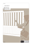
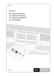
somfy.com
Dexxo Optimo RTS
EN
ES
PT
EL
Installation manual
Manual de instalación
Manual de instalação
Εγχειρίδιο εγκατάσταση̋
5056739C
GENERAL PRESENTATION __________________________________________________ 2
SAFETY INSTRUCTIONS ____________________________________________________ 2
Caution
Safety instructions
2
2
PRODUCT DESCRIPTION ____________________________________________________ 2
Product components
Area of application
2
2
POINTS TO CHECK PRIOR TO INSTALLATION __________________________________ 3
Preliminary checks
Safety instructions
3
3
INSTALLATION _____________________________________________________________ 3
Installation height
Detailed description of installation steps
3
3
PROGRAMMING ___________________________________________________________ 5
Programming button description
End limit setting and self-learning
Memorising remote controls for full opening cycle
5
5
5
OPERATING TEST __________________________________________________________ 6
Using the remote controls
Obstacle detection function
Built in lighting operation
6
6
6
CONNECTING PERIPHERALS ________________________________________________ 6
Description of the various peripherals
Electrical connections for the various peripherals
6
6
SETUP AND OPERATING OPTIONS____________________________________________ 7
General setup diagram
Meanings of the various parameters
Memorising the remote control for partial opening cycle
Memorising the remote control for controlling lighting
Memorising a Telis or similar type remote control
7
7
7
7
7
SPECIAL OPERATION _______________________________________________________ 7
CLEARING REMOTE CONTROLS AND ALL SETTINGS ____________________________ 7
Clearing remote controls
Resetting all settings
7
7
LOCKING PROGRAMMING ___________________________________________________ 7
REFITTING COVERS ________________________________________________________ 7
TECHNICAL SPECIFICATIONS ________________________________________________ 8
Dimensions
8
1
EN
CONTENTS
EN
GENERAL PRESENTATION
This product complies with the “safety, specific rules for powering vertically opening garage doors in residential use” requirements (standard EN 60335-2.95).
When installed in line with these instructions and in compliance with the “Installation Checklist”, the product will be compliant with standards EN
13241-1 and EN 12453.
The instructions referred to in the installation manual and instructions for use of this product are designed to prevent damage to property and personal
injury along with compliance with the above standards. Failure to comply with these instructions absolves Somfy from any liability resulting from
damage that may be caused. Dexxo Optimo RTS is a product that must be installed inside the garage with an integrated back-up control system.
Somfy hereby declares thatthe device is compliant with the essential demands and other relevant requirements of directive 1999/5/CE. A declaration
of compliance is available from the web site at www.somfy.com/ce (Dexxo Optimo RTS).
This product is suitable for use in the European Union and in Switzerland.
SAFETY INSTRUCTIONS
Caution
These are important safety instructions. Always follow the instructions, incorrect installation may lead to serious injury.
Safety instructions
Before installing the motor drive unit, remove all unessential lines or chains and switch off all equipment that is not essential for motorised door operation.
Before installing the motor drive unit, make sure that the door is in good mechanical condition, that it is properly balanced and that it opens and closes
correctly.
Locate all control systems at least 1.5 metres above floor level, making sure that they are visible from the entrance to the garage but safe from moving parts.
Position the manual release cord no more than 1.8 metres above floor level.
Where a removable release mechanism is used, we recommend storing it close to the door.
Fix the label describing the manual release procedure close to the release mechanism.
Fix the warning labels describing the hazards of door motion close to any fixed control mechanisms installed and make sure that the labels are clearly
visible to the user.
After installation, make sure that the mechanism is correctly adjusted and that the motor drive unit reverses its motion when the door encounters an
obstacle that is at least 50 mm from floor level.
After installation, make sure that no part of the door overhangs an area accessible to the public.
After installation, make sure that the motor drive unit inhibits or stops the door opening motion when the door is loaded down with a 20 kg weight
attached to a central position of the door’s bottom edge.
PRODUCT DESCRIPTION
Product components Fig. 1
Key.
1
2
3
4
5
6
7
8
9
10
11
12
13
14
Number
1
1
1
1
1
2
2
1
1
1
4
1
4
4
Area of application
Description
Motor head
Motor cover
Built-in light cover
Lintel bracket
Door bracket
Ceiling bracket
Motor head bracket
Manual release cord
Link arm
Travel stop
Chain retainer pad
Power cable
Hex. head M8x16 bolt
Hex. head M8x12 bolt & washer
Key.
15
16
17
19
20
21a
21b
21b1
21b2
22
23
24
25
26
Number
6
2
2
4
2
1
1
1
8
2
2
1
2
1
Description
HU8 nut
Shaft
Circlips
Self-shaping Ø 4x8 screw
Special screw for plastic Ø 3.5x12
Single part rail
Two part rail
Sleeve
Self-shaping Ø 4x8 screw
HM8 self-locking nut
Bracket
Spacer
Keytis / Keygo remote control
24 V 21 W E13 socket light bulb
Fig. 2
Types of doors (fig.2)
A: Projecting up and over door.
B: Sectional door:
- if the door’s upper profile is a specific one, use the “sectional door mounting bracket” ref.: 9009390.
C: Sideways opening sliding door:
- for side wall mounting, use:
- a belt transmission rail
- an “adjustable cranked arm” ref.: 9014481.
- for ceiling mounting, use:
- an “articulated arm” ref.: 9014482.
2
Door dimensions (Fig. 2)
For maximum door heights, the motor travel can be optimised:
).
• By fixing the lintel bracket to the ceiling, behind the lintel itself by up to 200 mm (Fig. 4-
EN
• By installing the motor head at a 90° angle (Fig. 6-
)
• By cutting the link arm to size.
POINTS TO CHECK PRIOR TO INSTALLATION
Preliminary checks
Check the garage door can be operated manually and runs smoothly. Ensure the door is in good mechanical condition (pulleys, mounts…) and is
correctly balanced (spring tension).
Remember that any work performed on door springs may be dangerous.
The structure of your garage (walls, lintel, inside surfaces, cross members, door rails…) are used to mount the Dexxo Optimo RTS system. Reinforce
them where necessary.
Never splash water onto the system. Never install Dexxo Optimo RTS in a location where water may cause damage.
The bottom edge of the door should be fitted with a rubber strip to avoid hard contact and enhance the contact surface.
If the garage door is the only entry point into the garage, fit an external release (external release keylock (ref. 9012961) or an external release
(ref. 9012962) and include a back-up battery (ref. 9001001).
If the garage door includes a separate pedestrian door, the door must be fitted with an interlock to prevent garage door movement when the pedestrian
door is open (pedestrian door safety kit ref. 2400657).
If the garage door opens on to a public road, install an indicator light, such as a flashing amber light (ref. 9015171).
If the garage door operates in automatic mode, install a photoelectric cell type safety system (ref. 9014994) and a flashing amber light type
indicator.
Make sure that the door does not comprise any accessible parts.
Unlocking the door may trigger uncontrolled door movement if the door is not balanced correctly.
Safety instructions
Safety instructions must be complied with throughout the installation process:
• Take off any personal jewellery (bracelet, chain or others) during installation work.
• During drilling and welding work, always wear safety glasses and suitable protection.
• Always use suitable tools.
• Take care when handling the motor drive system.
• Never connect the mains power supply or the battery back-up system before completing the installation process.
• Never use high pressure water systems for cleaning purposes.
INSTALLATION
Installation height Fig. 3
Measure the distance “D” between the door’s highest point and the ceiling.
If “D” is between 35 and 200 mm, mount the complete system straight onto the ceiling.
If “D” exceeds 200 mm, mount the complete assembly so that the height “H” falls between 10 and 200 mm.
Detailed description of installation steps Fig. 4 to 14
Mounting the lintel bracket and the door bracket (Fig. 4)
When installing the system directly onto the ceiling (flush with the ceiling), the lintel bracket can be mounted on the ceiling, if necessary recessed from
the lintel by up to 200 mm max. (Fig. 4- ).
Assembling the two part rail (Fig. 5)
[1] [2] [3]. Unfold the two parts of the rail.
[4]. Assemble the two parts of the rail using the sleeve.
[5]. Mount the complete assembly using the eight mounting screws.
The mounting screws must not penetrate the rail (do not drill).
When installing the system directly onto the ceiling, do not use the sleeve mounting screws.
3
Fitting the rail onto the motor head (Fig. 6)
EN
Fitting the complete assembly onto the garage ceiling (Fig. 7 à 9)
Fitting to the lintel bracket (Fig. 7)
Ceiling mounting
• Flush with the ceiling: mount the system directly onto the ceiling using the rail (Fig. 8).
It is possible to add mounting points at the motor head level (Fig. 8- ).
• Hung from the ceiling: two options:
- mount the system at the motor head (Fig. 9- a ).
- mount the system at the rail (Fig. 9- b ).
To add an adjustable intermediate mounting along the rail, or a mounting at a dimension h between 250 mm and 550 mm, use the ceiling mounting
kit ref.: 9014462 (Fig. 9- ).
Fitting the arm onto the door and the trolley (Fig. 10)
[1]. Release the trolley using the manual release cord.
[2]. Bring the trolley up to the door.
[3]. Attach the arm to the door bracket and the trolley.
Adjusting and fastening the opening travel stop (Fig. 11)
[1]. Release the trolley from the runner using the manual release mechanism and bring the door to the open position.
Do not open the door fully, but position it so that it does not reach its own travel stop.
[2]. Slot the travel stop (10) into the rail then turn it by 90°.
[3]. Position the travel stop against the trolley.
[4]. Moderately tighten down the mounting screw.
Do not tighten the mounting screw all the way down. Excessive tightening can damage the screw and cause the travel stop not
to remain in place.
Note : Do not use the travel stops supplied with the transmission rail.
Fitting the chain retainer pads (Fig. 12)
For chain rails only.
These pads are used to limit spurious noise linked to chain friction within the rail. Position each of the pads in the first hole in the rail after the travel stop.
Make sure that the pad is pressed in all the way so that its positioning pin is accessible outside of the rail.
Checking the chain or belt tension (Fig. 13)
The rails are supplied ready tensioned and inspected. If necessary, adjust the tensioning.
The rubber or tension spring must never be full compressed during operation.
Connecting the mains power supply (Fig. 14)
[1]. Remove the motor cover and the protective sheet.
[2]. Fit the light bulb.
[3]. Connect to the mains supply.
Plug the power cable into a suitable power outlet that complies with electric power requirements. The electric supply must be
suitably protected (a fuse or circuit breaker with a 5 A rating) and a residual current device (30 mA).
An omnipolar disconnection mechanism must be provided for the power supply:
. by using a power cord with a mains splug that can be disconnected, or
. by fitting a switch that ensures a contact separation distance of at least 3 mm for each pole (refer to standard EN60335-1).
Make sure that the manual release cord is located at a maximum height of 1.80 metres off the ground.
If necessary, extend the cord.
4
PROGRAMMING
EN
Programming button description
. Press for 2 s: memorise remote controls
. Press for 7 s: delete remote controls
+
SET
PROG
. Press for 0.5 s: call up and exit the setup menu
. Press for 2 s: start self-learning
. Press for 7 s: clear self-learning and settings
. Stop self-learning
P0
P1
Indicator light key:
. Modifying a setting value
. Using the forced mode
off
. Operation indicator light (red)
flashing
. End limit setting and self-learning indicator light (green)
. P0 - P1 parameters indicator (green)
P0
on
P1
End limit setting and self-learning Fig. 15
[1]. Press the “SET” button until the light comes on (2 s).
• The
indicator light flashes.
[2]. Control the motor using the “+” or “-” buttons so that the transmission system runner moves to link up with the trolley and closes the door.
• Pressing and holding the “-” button moves the runner in the close direction.
Release the “-” button before the motor has time to force against the door.
• Pressing and holding the “+” button moves the runner in the open direction.
[3]. Adjust the closed position using the “+” or “-” buttons.
Release the “-” button before the motor has time to force against the door.
[4]. Press “SET” to validate the closed end limit and start the self-learning cycle.
The door runs through a complete Open Close cycle and the
indicator light goes out.
• If the self-learning cycle was completed correctly, the
indicator light stays on.
• If the self-learning cycle was not completed correctly, the
indicator light continues to flash.
During self-learning:
• When the door is moving, pressing any button will stop the movement and stop the self-learning mode.
• When the door is stopped, pressing “SET” until the light comes on and the
indicator light comes off (2 s) will exit the self-learning mode.
The self-learning mode can be called up at any time even after the self-learning cycle has been completed.
Memorising remote controls for full opening cycle Fig. 16
Up to 32 control channels can be stored.
Running this procedure for a previously stored channel will clear it.
At this stage in the installation process, the Dexxo Optimo RTS motor drive unit is ready to run.
5
EN
OPERATING TEST
Using the remote controls Fig. 17
Obstacle detection function Fig. 18 and 19
The detection of an obstacle during door opening will stop the door (Fig. 18).
The detection of an obstacle during door closure will reopen the door (Fig. 19).
Make sure that obstacle detection works when the door encounters an obstacle 50 mm from the ground.
Built in lighting operation
The light will come on every time the motor drive unit is operated. It will go out automatically after one minute once the door stops. Repetitive use
which causes the light to stay on continually may result in an automatic cut-off condition triggered by the thermal cut out protection mechanism.
CONNECTING PERIPHERALS
Description of the various peripherals Fig. 20
Key
Description
Amber light
Code keypad
Keyswitch
Aerial
Battery
Pedestrian door safety kit
Photoelectric cells
1
3
4
5
6
7
8
Electrical connections for the various peripherals Fig. 20 to 22
Cut the electric power supply to the motor before performing any work on peripherals. The
check the wiring (for possible short circuits or polarity reversals).
indicator light remains off after working on the system,
General electrical diagram (Fig. 20)
Pedestrian door safety kit
When the pedestrian door contact is fitted, it must be connected in place of the jumper normally fitted between terminals 3 and 4.
If the pedestrian door contact is removed, the jumper between terminals 3 and 4 must be refitted.
Photoelectric cells (Fig. 21)
When fitting photoelectric cells, connect the receiver cell (RX) to the input in place of the jumper fitted between terminals 5 and 6.
If the cells are removed, the jumper between terminals 5 and 6 must be refitted.
Code keypad (Fig. 22)
6
SETUP AND OPERATING OPTIONS
EN
General setup diagram Fig. 23
Meanings of the various parameters
Programming example: adjusting the long slowdown zone “P1=3” (Fig. 24)
Code
P0
Description
Obstacle detection sensitivity
P1
Closure approach speed
Values
1
2
3
4
: low sensitivity
: low sensitivity
: standard
: high sensitivity
1
2
3
: no slowdown
: short soft stop
: long soft stop
Comments
If this setting is changed, it is essential to run the force measurement
sequence at the end of the installation procedure
P1=1: no slowdown before closure.
P1=2: speed is reduced during the last 20 centimetres.
P1=3: speed is reduced during the last 50 centimetres.
If this setting is changed, it is essential to run the force measurement
sequence at the end of the installation procedure.
Memorising the remote control for partial opening cycle Fig. 25
Memorising the remote control for controlling lighting Fig. 26
Memorising a Telis or similar type remote control Fig. 27
SPECIAL OPERATION
Refer to the User’s Manual.
CLEARING REMOTE CONTROLS AND ALL SETTINGS
Clearing remote controls Fig. 28
Press the “PROG” button until the light blinks (7 s).
This clears all of the remote controls memorised.
Resetting all settings Fig. 29
Press the “SET” button until the light goes out (7 s).
This clears all previously stored settings and returns them to their default values.
LOCKING PROGRAMMING (Fig. 30)
Used to lock the programming settings (end limit setting, self-learning, setup).
Simultaneously press the “SET”, “+” and “-” buttons:
- start by pressing “SET”.
- pressing “+” and “-” must take place within two seconds.
Pressing the “SET” button then no longer has any effect.
The remote control memorising functions (“PROG” button) and forced mode operation (“+”, “-” buttons) remain possible.
To access programming mode once again, repeat the same procedure.
REFITTING COVERS (Fig. 31)
Position the aerial and fit the covers.
To ensure proper remote control range, the aerial must be fitted in one of the two positions shown in Figure 31.
7
TECHNICAL SPECIFICATIONS
EN
Dexxo Optimo RTS
BASIC TECHNICAL CHARACTERISTICS
Mains power supply
Max. power consumption
Traction force
230 V - 50 Hz
4 W - 120 W
800 N
650 N
20 cycles per day max. tested for 36,500 cycles
Standby-Operation
Peak force
Starting force (1)
Use
Number of Opening/Closing cycles per day
Max. speed
Programming interface
Operating temperature
Travel end limits
14 cm/s
4 buttons - 4 indicator lights
- 20 °C/ + 60 °C- indoor dry - IP 20
Mechanical stopper at opening
Memorized end limit position at closing
Electrical insulation
Class 2: double insulation
24 V / 21 W; E13 socket
RTS 433,42 MHz
32
Built in lighting
Somfy radio frequency
Number of channels that can be memorised
CONNECTIONS
Safety input
Type
Compatibility
Dry contact: NC
Photoelectric TX/RX cells
Dry contact: NC
Dry contact: NO
24 V - 15 W with built in flashing control
24 V - 500 mA max
Yes: RTS aerial compatible (Réf. 2400472)
Yes: battery pack compatible (Réf. 9001001)
24 hours; 5 to 10 cycles depending on door
Charge time: 48 hours
Pedestrian door safety input
Wired control input
Amber light output
Accessory power supply output
Remote aerial input
Backup battery input
Autonomy
OPERATION
Forced operation mode
Independent lighting control
Lighting time delay (after movement)
Amber light pre-warning
Safety input operation
By pressing and holding the motor control button
Yes for built-in lighting
Fixed 60 s
2 s automatic if light connected
Fully reopens
None
While closing
Before opening
(Dangerous Movement Area
Accessible to the Public)
Built-in obstacle detection
Operation after obstacle detection
Progressive start up
Opening speed
Closing speed
Closure approach speed
Adjustable sensitivity: 4 levels
Full re-opening
Yes
Set: 14 cm/s (max.)
Set: 12 cm/s (max.)
Programmable: does not slow down, short slowdown zone (30 cm),
long slowdown zone (50 cm)
(1) Maximum load for motor to start and drive door for at least 5 cm (according to RAL-GZ definition).
Dimensions
Overall length: 3,295 / 3,895
171 min
140
Available travel: 2,555 / 3,155
65.5
125
224.4
63.6
Fixation: 2,982 / 3,582
313.6
254.1
106
130.9
33.5
164.4
139.5
Rail: 2,900 / 3,500
404.2
Overall length: 3,153 / 3,753
150.1
404.2
Rail : 2,900 / 3,500
112.2
224.4
8
somfy.com
EN
Dexxo Optimo RTS
User Manual
CONTENTS
GENERAL PRESENTATION __________________________________________ 2
The world of Somfy
Support
2
2
SAFETY INSTRUCTIONS ____________________________________________ 2
Standards
Safety instructions
2
2
PRODUCT PRESENTATION __________________________________________ 2
OPERATION AND USE ______________________________________________ 3
Normal operation
Special operation
3
4
PERIPHERALS _____________________________________________________ 5
MAINTENANCE ____________________________________________________ 5
Replacing the bulb in the light unit
Checking
Battery replacement
5
6
6
TECHNICAL SPECIFICATIONS ________________________________________ 6
"
5056739C
1
GENERAL PRESENTATION
EN
Thank you for choosing a Somfy product. This product is designed and manufactured by Somfy in line with quality procedures that are ISO 9001 compliant.
The world of Somfy
Somfy develops, produces and sells automation systems for residential and commercial applications. Alarm systems, automatic blinds and shutters,
garage doors and gates - all Somfy products are designed to fulfill your needs in terms of safety, comfort and security.
At Somfy, the quest for quality is a continual process. Somfy has built its reputation on the quality of its products and is synonymous with innovation
and technological leadership worldwide.
Support
Getting to know you, listening, answering your needs, is all part of the Somfy approach.
Please contact your local Somfy retailer or installer for details on other Somfy products.
Internet: www.somfy.com
© SOMFY. SOMFY SAS, capital 20.000.000 Euros, RCS Bonneville 303.970.230
SAFETY INSTRUCTIONS
Standards
This product complies with the “safety, specific rules for powering vertically opening garage doors in residential use” requirements (standard EN 60335-2.95).
When installed in line with these instructions and in compliance with the “Installation Checklist”, the product will be compliant with standards EN 13241-1 and
EN 12453.
The instructions referred to in the Installation Manual and Instructions for Use of this product are designed to ensure that damage to property and
injury to persons is avoided along with compliance with the above standards. Failure to comply with these instructions absolves Somfy from any
liability for any damage that may be caused. Dexxo Optimo RTS is a product that must be installed inside the garage with a built-in back-up control
system.
Somfy hereby declares that the device is compliant with the essential demands and other relevant requirements of directive 1999/5/CE. A declaration
of compliance is available from the web site at www.somfy.com/ce (Dexxo Optimo RTS).
This product is usable in the European Union and in Switzerland.
These are important safety instructions. For safety reasons, it is important to always follow all instructions.
Retain these instructions for future reference.
Safety instructions
Every month, test that the motor drive unit reverses its motion when it encounters an obstacle that is at least 50 mm from ground level. If this is not
the case, call your installation specialist. Always be very careful when using the manual release cord for a manually operated door may fall quickly
due to weak or broken springs or if it is badly balanced.
Before manually operating the door or performing maintenance work, always turn the power off and where necessary remove the battery (Fig. 1).
Never let children play with door control systems. Keep the remote controls out of reach of children (Fig. 2).
When replacing the light bulb, select a 24 V 21 W E13 type (Fig. 3).
Regularily check the operation of the door to identify any sign of wear, deterioration or incorrect balancing. Do not operate the door if repairs or
adjustments are required.
Remain at a safe distance when operating the door.
1
2
3
SE
T
24V 21W max.
PRODUCT PRESENTATION
Description (Fig. 4)
The Dexxo Optimo RTS system is designed to power garage doors in residential use.
This motor drive system comprises:
• A motor head (1) with integrated light (2).
• A rail assembly (3) with a manual release cord (4).
2
4
OPERATION AND USE
EN
Normal operation
Full opening cycle using Keytis or similar remote controls (Fig. 5a)
5a
Partial opening cycle using Keytis or similar remote controls (Fig. 5b)
5b
Obstacle detection operation (Fig. 6 and 7)
When an obstacle is detected during the open cycle, the door will stop (Fig. 6).
When an obstacle is detected during the close cycle, the door will stop and then reopen (Fig. 7).
Once an obstacle has been detected, the light will flash for 30 seconds.
7
6
Light operation
The light will come on each time the motor drive unit is operated. The light will go out one minute after the door stops moving. Repetitive use that
causes the light to be continually on may result in a thermal cut out (this will automatically turn the light off).
Manual release cord operation (Fig. 8)
Dexxo Optimo RTS is fitted with a manual release mechanism so that you can move the door manually should a power failure occur, for example. The
manual release mechanism should be easily accessible and located no more than 1.80 metres above floor level.
[1]. Disengaging the motor drive mechanism
Pull on the manual release cord until the door drive mechanism is disengaged.
[2]. Manually moving the door
This is possible as long as the door drive mechanism is disengaged.
[3]. Reengaging the motor drive mechanism
Move the door manually until the drive mechanism comes to reengage itself into the transmission rail.
8
When disengaging the motor drive mechanism, use caution for a badly balanced door may cause sudden door
movement that may be dangerous.
Only use the cord to disengage the motor drive mechanism. Never use the cord to move the door manually.
Always reengage the motor drive mechanism before sending another command to the motor drive unit.
3
EN
Special operation
Depending on the peripherals installed and the operating options set by your installer, the Dexxo Optimo RTS system may perform the following
special operations:
Full opening cycle using Telis or similar remote controls (Fig. 9a)
9a
Partial opening cycle using Telis or similar remote controls (Fig. 9b)
9b
Safety photoelectric cell operation
An obstacle detected between the cells will prevent the door from closing.
The door will stop and then reopen when an obstacle is detected during the close cycle.
The light will flash for 30 seconds during this process.
Pedestrian door safety function
Opening a pedestrian door within the garage door will prevent the door from moving.
The light will flash for30 seconds during this process.
Flashing amber light
The amber light comes on whenever the door moves, with a two second advance warning before the start of door motion.
Working from the back-up battery
If a back-up battery is installed, the Dexxo Optimo RTS motor will operate when a power cut occurs.
The following conditions apply to operation:
• Door speed is reduced.
• The light will not come on.
• The safety devices are disabled.
Battery specifications:
• Endurance: the battery will last for 24 hours with a maximum of 5 to 10 operating cycles depending on the weight of the door.
• Recharging time: 48 hours.
• Service life prior to replacement: approx. three years.
To ensure optimum battery life, we recommend that the power to the motor is switched off and the door is operated for a number of cycles using
battery power (three times a year).
Forced operation mode (Fig. 10)
This function is used to move the door at any time (remote control lost, safety mechanism failure, etc.).
Remove the built-in lighting cover:
• Control door motion using the “+” and “-” buttons.
• Pressing and holding the “-” button will trigger closure.
• Pressing and holding the “+” button will trigger opening.
10
4
PERIPHERALS
EN
A number of peripherals are available.
11
Key
Description
Comments
1
Keytis 2NS RTS remote control
Hand held 2 channel remote control.
2
Keytis 4NS RTS remote control
Hand held 4 channel remote control.
3
KEYGO remote control
Four channel keyring remote control.
4
RTS pushbutton
Wall mounted 2 channel remote control switch.
5
RTS radio code keypad
Access code control point. For use outside the garage.
6
Photoelectric cells
To prevent door closure if an obstacle is detected.
7
Amber light
To signal a warning when the door operates.
8
Keyswitch
Keyswitch for secure control.
9
Battery
To provide continued operation during a power cut.
10
Release lock
To engage the manual release system from the outside using the existing door handle.
Highly recommended when the garage door is the only access point into the garage.
11
Outside release lock
To engage the manual release system from the outside using the existing door handle.
Highly recommended when the garage door is the only access point into the garage.
12
Door locking kit
A system to reinforce door locking.
MAINTENANCE
Replacing the bulb in the light unit (Fig. 12)
[1] [2]. Remove the light cover.
[3] [4]. Unscrew and replace the defective light bulb.
[5] [6] [7]. Refit the light cover.
Use a 24 V 21 W E13 socket light bulb.
12
P0
P1
+
P0
P1
SET
+
SET
24 V 21 W max.
P0
P1
+
SET
5
Checking
Every six months, check that the door reverses direction when an obstacle prevents the door from closing (at least 50 mm above floor level).
The safety mechanisms (cells, pedestrian door contact)
Check correct operation every six months (refer to page 4).
The back-up battery
To ensure optimum battery life, we recommend that the power to the motor is switched off and the door is operated for a number of cycles using
battery power (three times a year).
Battery replacement
Keytis
Keygo
13b
C
13a
430
R2
4 30
R2
C
C
EN
The obstacle detection function
430
R2
3V
CR 2430
3V
CR 2430
+
3V
CR 24
30
+
+
RECYCLING
Do not dispose of your scrapped appliances, nor your used batteries with household waste. You are liable to dispose of all your
electronic or electrical equipment waste by relocating over to a dedicated collection point for recycling.
TECHNICAL SPECIFICATIONS
Basic technical specifications
Mains power supply
Power consumption on standby
Max. power consumption
Traction force – Peak force
Use
Number of channels that can be memorised
Somfy radio frequency
Integrated light
Operating temperature
6
230 V - 50 Hz
4W
120 W
800 N
20 cycles per day with a standard rail (tested for 36,500 cycles)
32
433,42 MHz RTS
24 V / 21 W max. E13 socket
-20 °C / +60 °C