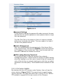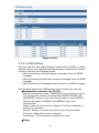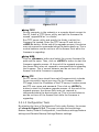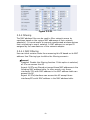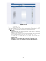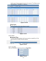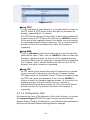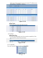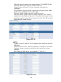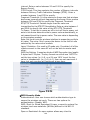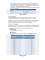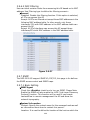
1
Lantech IWP-2000-65 Industrial 802.11 a/b/g IP65 Redundant Access Point w/MESH User’s Manual IWP-2000-68 User’s Manual Release 1.0 ii Table of Contents Caution .................................................................................................vi 1. Introduction .......................................................................... 2 1-1. Overview of IWP-2000-65 ............................................................. 2 1-2. Specification .................................................................................. 3 1-3. Package Contents .......................................................................... 5 2. Installation ............................................................................ 6 2-1. Full View of IWP-2000-65 ............................................................. 6 2-2. Full View of POE Injector ............................................................... 7 2-3. Mount Kit for IWP-2000-65 ........................................................... 7 2-4. System Requirements .................................................................... 8 2.4.1 Inline Power Injector (PoE) ................................................... 8 2.4.2 Preparing Installation ............................................................ 8 3. Operation of Web-based Management ...................................... 10 3.1 Basic Configuration ....................................................................... 10 3.2 AP-Bridge Mode ............................................................................ 11 3.2.1 System ................................................................................. 12 3.2.2 LAN Configuration ................................................................ 21 3.2.3 Wireless ............................................................................... 23 3.2.4 Filtering ................................................................................ 27 3.2.5 SNMP .................................................................................... 28 3.2.6 Tools .................................................................................... 33 3.2.7 Log Out................................................................................. 33 3.3 AP-CB-Bridge Mode ....................................................................... 34 3.3.1 System ................................................................................. 34 3.3.2 LAN Configuration ................................................................ 43 3.3.3 Wireless ............................................................................... 44 3.3.4 Filtering ................................................................................ 53 3.3.5 SNMP .................................................................................... 54 3.3.6 Tools .................................................................................... 59 3.3.7 Log Out................................................................................. 59 3.4 AP-CB-Route Mode ........................................................................ 60 3.4.1 System ................................................................................. 61 3.4.2 WAN Configuration ............................................................... 69 3.4.3 LAN Configuration ................................................................ 70 3.4.4 Wireless ............................................................................... 71 3.4.5 Filtering ................................................................................ 79 3.4.6 SNMP .................................................................................... 81 3.4.7 Tools .................................................................................... 86 3.4.8 Log Out................................................................................. 86 3.5 CB-CB-Route Mode ........................................................................ 87 3.5.1 System ................................................................................. 88 3.5.2 WAN Configuration ............................................................... 95 3.5.3 LAN Configuration ................................................................ 97 3.5.4 Wireless ............................................................................... 98 3.5.5 Filtering .............................................................................. 101 iii 3.5.6 SNMP .................................................................................. 103 3.5.7 Tools .................................................................................. 108 3.5.8 Log Out............................................................................... 108 3.6 VLAN AP Mode ............................................................................ 109 3.6.1 System ............................................................................... 109 3.6.2 LAN Configuration .............................................................. 117 3.6.3 Wireless ............................................................................. 117 3.6.4 Filtering .............................................................................. 122 3.6.5 SNMP .................................................................................. 123 3.6.6 Tools .................................................................................. 128 3.6.7 Log Out............................................................................... 128 3.7 AP_WDS_Bridge Mode ................................................................ 129 3.7.1 System ............................................................................... 129 3.7.2 LAN Configuration .............................................................. 138 3.7.3 Wireless ............................................................................. 139 3.7.4 Filtering .............................................................................. 144 3.7.5 SNMP .................................................................................. 145 3.7.6 Tools .................................................................................. 150 3.7.7 Log Out............................................................................... 150 3.8 AP4 WDS Bridge Mode ................................................................ 151 3.8.1 System ............................................................................... 151 3.8.2 LAN Configuration .............................................................. 160 3.8.3 Wireless ............................................................................. 161 3.8.4 Filtering .............................................................................. 170 3.8.5 SNMP .................................................................................. 171 3.8.6 Tools .................................................................................. 176 3.8.7 Log Out............................................................................... 176 3.9 OLSR_AP Mode............................................................................ 177 3.9.1 System ............................................................................... 178 3.9.2 WAN Configuration ............................................................. 185 3.9.3 LAN Configuration .............................................................. 187 3.9.4 MESH .................................................................................. 188 3.9.5 Wireless ............................................................................. 192 3.9.6 Filtering .............................................................................. 199 3.9.7 SNMP .................................................................................. 200 3.9.8 Tools .................................................................................. 205 3.9.9 Log Out............................................................................... 205 3.10 AODV_AP Mode ......................................................................... 206 3.10.1 System ............................................................................. 206 3.10.2 WAN Configuration ........................................................... 214 3.10.3 LAN Configuration ............................................................ 216 3.10.4 MESH ................................................................................ 217 3.10.5 Wireless ........................................................................... 218 3.10.6 Filtering ............................................................................ 225 3.10.7 SNMP ................................................................................ 226 3.10.8 Tools ................................................................................ 231 3.10.9 Log Out............................................................................. 231 iv Revision History Release Date Revision 1.0 12/31/2010 A1 v Caution Circuit devices are sensitive to static electricity, which can damage their delicate electronics. Dry weather conditions or walking across a carpeted floor may cause you to acquire a static electrical charge. To protect your device, always: Touch the metal chassis of your computer to ground the static electrical charge before you pick up the circuit device. Pick up the device by holding it on the left and right edges only. The Web UI’s Main Menu links are used to navigate to other menus, and display configuration parameters and statistics with suggestive value 1024x768. If you need using outdoor device connects to this device with cable, then you need to add an arrester on the cable between outdoor device and this device. vi About this user’s manual In this user’s manual, it will not only tell you how to install and connect your network system but configure and monitor the IWP-2000-65 through the built-in web UI step-by-step. Many explanations in details of hardware and software functions are shown as well as the examples of the operation for web-based interface. Overview of this user’s manual Chapter 1 ‘Introduction’ describes the features of IWP-2000-65 Chapter 2 ‘Installation’ Chapter 3 ‘Operation of Web-based Management’ 1 1. Introduction 1-1. Overview of IWP-2000-65 The IWP-2000-65 is a 802.11a/b/g Dual Radio Outdoor Multi-Function Wireless Access Point with Power over Ethernet (PoE) supported. The IWP-2000-65 also operates as multi-function wireless system that includes MESH, Point-to-Point/Point-to-Multipoint Bridge, Access Point, Wireless Client, and Repeater. The dual radio of IWP-2000-65 can be functioned dual band and maintain each radio up to 54Mbps data rate simultaneously on both directions. Key Features in the Device • Dual Radio: Two high-power IEEE 802.11 a/b/g radio for backhaul and local access. • Multi operating modes support: OLSR_AP, AODV_AP, AP-Bridge, AP-CB-Bridge, AP-CB-ROUTE, CB-CB-ROUTE, VLAN-AP , AP_WDS_BRG, AP4_WDS_BRG • Bandwidth limitation: Traffic shaping by IP in MESH and ROUTE model up to 30 list • Power over Ethernet • PoE Power Forwarding • Mac filtering • IP filtering • QOS (WMM) Enhance performance and density • LLDP Link Layer Discovery Protocol • Up to 8 SSID support. • Supports WEP 64/128, WPA, WPA2 encryption • Support SNMP V1/V2c/V3 • Support STP/RSTP • IP65 Industrial standard 2 1-2. Specification General Data Rates Standards 802.11b: 1, 2, 5.5, 11Mbps 802.11g: 6,9,12,18,24,36,48,54 Mbps 802.11a: 6,9,12,18,24,36,48,54 Mbps IEEE802.11 a/b/g, IEEE802.1x, IEEE802.3, IEEE802. 3u,IEEE802.3af Power Requirements Active Ethernet (Power over Ethernet) 48 VDC/0.37 5A External Power Unit: Auto sensing 100/240 VAC; 50/60 Hz Regulation Certifications FCC/CE (by request), IP65 Hard Ware Information CPU Intel IXP 425 533MHz network processor Interface Flash 1* RJ-45 Ethernet Port (for POE input) 1* RJ-45 Ethernet Port (for POE power forwarding) 16MB Memory 64MB SDRAM RF Information Output power (+1.5/-2dBm) 802.11a 22dBm@6Mbps 19.5dBm@36Mbps 20dBm@48Mbps 18dBm@54Mbps 802.11b 24.5dBm@11Mbps 802.11g 24.5dBm@6~24Mbps 22.5dBm@36Mbps 21.5dBm@48Mbps 21dBm@54Mbps Sensitivity (Typical) 802.11a -91dBm @ 6Mbps, -72dBm @ 54Mbps 802.11b -97dBm @ 1Mbps, -88dBm @ 11Mbps 802.11g -91dBm @ 6Mbps, -74dBm @ 54Mbps Networking Information Topology Ad‐ Hoc, Infrastructure Operation Model OLSR_AP, AODV_AP, AP-Bridge, AP-CB-Bridge, AP-CB-ROUTE, CB-CB-ROUTE, VLAN-AP , 3 AP_WDS_BRG, AP4_WDS_BRG SSID Multiple SSID Interface Two 10/100Mbps RJ‐ 45 LAN Ports Security STP/RSTP •IEEE802.1x / RADIUS Client (TTLS, PEAP) Support i n AP Mode •IEE802.1x Supplicant (TTLS, PEAP) support in Client Bridge Mode •WPA-WiFi Protected Access •WPA2 (802.11i) •WEP 64,128 bits •IP address filtering •MAC address filtering •Layer2 Isolation •VLAN tunneling Support •Hide SSID •Rogue AP Scan STP/RSTP QOS WMM Bandwidth limitation Traffic shaping by IP address in MESH and ROUTE mode Management Features IP Auto‐ configuration DHCP client/ server SNMP V1/V2c/V3 LLDP Link Layer Discovery Protocol NTP Support NTP client Remote Configuration Web‐ based configuration (HTTP/HTTPS) Firmware Upgrade Upgrade firmware via WEB, TFTP and FTP Max Client 32 users (simultaneously) per radio Network management Lantech View Environmental Temperature Range • Operating: -20°C to 70°C • Storage: -40°C to 80°C Humidity (non-condensing) 5%~95% Typical 4 1-3. Package Contents Make sure that you have following items: 1. 1 x IWP-2000-65 Outdoor Wireless Access Point unit 2. 1 x 100~240VAC, 50~60Hz AC to 48V/0.375A DC switching adapter 3. 1 x Inline Power Injector (PoE) 4. 1 x Grounding wire 1.8m 5. 1 x RJ-45 CAT-5 Cross-over Ethernet cable 1.8m 6. 1 x RJ-45 CAT-5 Ethernet cable 30m (optional) 7. 2 x Strain Relief 8. 1 x User manual CD 9. 2 x 7dBi dual band Omni Antenna 10. 1 x Pole mount kit and Screws pack 1. Main Unit 2. Power Adapter 3. Inline Power Injector (PoE) 4. 1.8m Grounding wire 5. 1.8m cable 6. 30m cable (optional) 7. Strain Relief 8. User manual CD 9. Antenna 10. Pole mount kit and screws pack Please notify your sales representative immediately if any of the aforementioned items is missing or damaged. 5 2. Installation 2-1. Full View of IWP-2000-65 Interface on the IWP-2000-65 Unit: eth1: For connecting the RJ-45 CAT-5 Ethernet cable to receiving the power and for user to configure the Access Point. eth0: For connecting and provide power to other device, such as IPCAM. By default it is disabled. eth1 eth0 *Please note: the voltage supply by eth0 is 48V and maximum output power (watt) is the outcome of AP’s power usage deduct from total input power. For example, with standard power adaptor, the total input power is 48V x 0.375A = 18W. The AP use about 6W when it’s full load. Therefore, the maximum power that eth0 can support is about 12W. N-type antenna connector: for connecting N-type antennas. Antenna 1 (ath0~3) Antenna 2 (ath4~7) 6 2-2. Full View of POE Injector Interface on the Inline Power Injector: PC/SW (Data Input) Port 3: for connecting cross-over Ethernet Cable to PC or straight Ethernet cable to Hub, Switch or Router. DC Input Port 4: power adapter 48V, 0.375A DC input. AP/CB (Power & Data Output) Port 5: for connecting an Ethernet Cable to the AP. Grounding Port 6: for connecting grounding wire. 6 5 POE picture1 4 3 POE picture2 Power and Data Interface location on the PoE denoted by numbers 3-6. 2-3. Mount Kit for IWP-2000-65 The IWP-2000-65 can be mounted on a pole; user can use the Pole Mount kit to mount the IWP-2000-65 as shown in Figure 2-1. Figure 2-1 7 2-4. System Requirements Installation of the IWP-2000-65 Outdoor Wireless unit requires the following: 1. A PC with 10/100/1000 Ethernet port and web browser (e.g. Internet Explore or Firefox). 2. RJ-45 Ethernet cable connected to the Ethernet network. 3. An AC power outlet (100~240V, 50~60Hz) supplies the power. 2.4.1 Inline Power Injector (PoE) The IWP-2000-65 is equipped with an Inline Power Injector module. The Inline Power Injector (PoE) delivers both data and power to IWP-2000-65 via Ethernet cable, and gives the following benefits to improve the performance vs. installation cost ratio. This works great in areas where you may not have power, like house roof. This also allows you to place the IWP-2000-65 unit closer to the antenna, to make installation easier more thus reducing signal loss over antenna cabling. Ethernet signal travels well over CAT 5 cable but 2.4GHz/5GHz signal doesn't do as well over antenna cabling. Ethernet cabling is much cheaper than Antenna cabling. 2.4.2 Preparing Installation Before installing IWP-2000-65 for outdoor application or hard-to-reach location, we recommend configure and test all the devices first. For configuring the IWP-2000-65, please follow the quick steps below to power up the IWP-2000-65. Refer to Figure 2-2 for steps 1 through 4. 8 Figure 2-2 Step1: Connect the DC plug of the AC/DC power adapter into the DC Input Port of Inline Power Injector and the AC plug into a power outlet. The Green LED on the Inline Power Injector will light up. Step2: Connect the cross-over Ethernet cable from PC/SW Port to the Ethernet port on a PC. Step3: Connect another Ethernet cable to the eth1 on IWP-2000-65. Hand tightens the water proof strain relief after you connect the connector. Step4: Connect the remaining end of the CAT 5 cable into the labeled AP/CB port on PoE injector. This is the power side of the PoE that will power up the IWP-2000-65. When the IWP-2000-65 receives power over the Ethernet cable, the IWP-2000-65 will start its boot up sequence. User can configure the IWP-2000-65 via HTML browser, such as Microsoft Internet Explorer or Fire Fox from a remote host or PC. 9 3. Operation of Web-based Management 3.1 Basic Configuration This chapter instructs user how IWP-2000-65 through the web user interface. to configure and manage the The default values of the AP are listed in the table below: IP Address 192.168.1.1 Subnet Mask 255.255.255.0 Gateway Address 192.168.1.254 Username admin Password admin Table 3-1 Open your web browser and enter the default IP http://192.168.1.1 in the address bar, it will show the following screen (see Fig.3-1) and ask user enter the username and password. The default username and password are both ‘admin’. For the first time to use, please enter the default username and password, then click the <LOGIN> button. The login process now is completed. To optimize the display effect, we recommend user use Microsoft IE 7 or above, FireFox 3 or above and have the resolution 1024x768. Web Access Procedures Now user can use web browser to configure IWP-2000-65. The following procedure explains how to configure each item. Step1: Open your web browser and enter the IP Address (192.168.1.1 as default) Step2: Press <ENTER> key and the IWP-2000-65 Login screen will appear as shown in Figure 3-1. 10 Figure 3-1 Step3: Enter ‘admin’ in the Username and Password fields, and click <LOGIN> to enter the web configuration page as shown in Figure 3-2. This page includes all basic configurations for the Access Point. The items are list in left hand side of the menu. Figure 3-2 3.2 AP-Bridge Mode The default operating model for IWP-2000-65 is AP-Bridge; this model is to set the device as a normal AP. The functions and settings are list as following: ▽ SYSTEM ● Administrator ● Firmware ● Configuration Tools 11 ● ● ● ● ● ● ● General Status Power Control Bridge Status WIFI Status Log System time Reboot ▽ LAN ● Bridge LAN settings ▽ WIRELESS ● WIFI ath0 ● WIFI ath1 ● WIFI ath2 ● WIFI ath3 ● WIFI ath4 ● WIFI ath5 ● WIFI ath6 ● WIFI ath7 Setting Setting Setting Setting Setting Setting Setting Setting ▽ FILTER ● MAC Filtering ▽ SNMP ● Basic Setting ● VACM Setting ● Trap Setting ▽ Tools ● Tools ▽ Log Out 3.2.1 System This page shows the current status and some basic settings of the device, including Administrator, Firmware, Configuration Tools, General Status, Power Control, Bridge Status, WIFI Status, Log, System Time and Reboot; screen as shown in Figure 3-2-1 12 Figure 3-2-1 3.2.1.1 Administrator By selecting the item of Administrator under System, User will see the screen shown in Figure 3-2-2. These settings allow user to configure the device Name, language, model, password, remote management and WIFI Loading Warning Threshold. Device Name This is a host name or system name for the device. The maximum length is 20 characters. User can only input '0'~'9', 'a'~'z', 'A'~'Z', '_' or '-'. Language Select This function allows user to select a language for the UI, the options available are: English, Simplified Chinese and Traditional Chinese. Model Select OLSR-AP: To set this device as an AP with layer 3 MESH function. AODV-AP: To set this device as an AP with layer 3 MESH function. AP-Bridge: To set this device as a normal AP. AP-CB-Bridge: To set this device as an AP and Client Bridge device. AP-CB-ROUTE: To set this device as a router device with AP and CB functions. CB-CB-ROUTE: To set this device as a router device with dual CB functions. VLAN-AP: To set this device as a VLAN AP device. Each SSID can have its own VLAN ID. AP_WDS_BRG: To set this device as a WDS device with AP function. AP4_WDS_BRG: To set this device as WDS device with AP function and support up to 4 SSID. 13 Figure 3-2-2 Password Settings If user wants to change the password for admin account, the user should enter the current password, a new password and, re-type the new password. The Idle Time Out is the amount of time of inactivity allowed before user proceeds next action. The user needs to re-login if the idle time passes timeout Remote Management User can enable/disable the management of the Access Point from a remote host. Just tick the <Enable> check box and enter an IP address of the remote host. Then, only the host with the entered IP address can access this device. WIFI Loading Warning Threshold The threshold value is used by Lantech View network management system. Lantech View will monitor the WIFI loading, when the loading is over this value, Lantech View will change the color of the link line on network topology to notify the user about condition of the link quality. The threshold value is between 5 and 25. 3.2.1.2 Firmware Update By selecting the item of Firmware under System, User will see the screen shown in Figure 3-2-3. This page shows current firmware version and date. This page also allow user to using TFTP or WEB or FTP method to upgrade to the new version of the firmware. 14 Figure 3-2-3 Using TFTP On any computer in the network or a compute direct connect to the AP. Install a TFTP Server utility, and put the firmware file named ‘upgradeFW.tar’ in a folder. Run TFTP server utility and specify the folder in which the firmware file located. Enter the TFTP server IP and click on <APPLY> button. At the end of the upgrade process, this device may not respond to commands before the device boots up. This is normal behavior and do not turn off the Access Point while the firmware is upgrading. Using WEB Click on <Browse> button and select the correct firmware file path and file name. Then, click on <APPLY> button to start the firmware upgrade process. At the end of the upgrade process, the Access Point may not respond to commands while uploading the firmware. This is normal behavior and do not turn off the Access Point while firmware is upgrading. Using FTP On FTP server, there should have valid firmware which includes fs-opn.img and/or kernel-opn.img. On the Firmware Update FTP page, enter the IP address of the FTP server, firmware name and FTP user name and password. Then click on <APPLY> button to start the firmware upgrade process. At the end of the upgrade process, the Access Point may not respond to commands before the device boots up. This is normal behavior and do not turn off the Access Point while the firmware is upgrading. 3.2.1.3 Configuration Tools By selecting the item of Configuration Tools under System, the screen will show in Figure 3-2-4. This page includes three selections: Restore Factory Default Configuration, Local Backup settings/Restore settings and Remote Backup Settings/Restore settings. 15 Figure 3-2-4 Restore Factory Default Configuration: To reset configuration settings to the factory default values, just click on <NEXT> button beside ‘Restore Factory Default Configuration’. Figure 3-2-5 Then click on <Restore> button on next page, now the system will reset to factory default value. Figure 3-2-6 Local Backup Settings/Restore settings To backup or restore the configuration for this device, click on <NEXT> button beside ‘Local Backup settings/Restore settings’, Figure 3-2-7 Click on <Backup Settings> button on next page to save the settings of this device to a file named ‘configs.tar’ on user’s PC. To restore the settings, click on <Browse> button and select the correct file path and file name. Then, click on <Restore Settings> button to start the restore settings process. 16 Figure 3-2-8 Remote Backup Settings/Restore settings User can also backup/restore the configuration of this device remotely. Click on <NEXT> button beside ‘Local Backup settings/Restore settings’, Figure 3-2-9 Enter the necessary setting in next page, then click on <Backup To Server> or <Restore From Server> to start the process. Figure 3-2-10 3.2.1.4 General Status In this page user could see the detail settings of this device, including the System Information, Power Control, Bridge LAN port, AP WIFI 1 Status, AP WIFI 2 Status. 17 Figure 3-2-11 18 3.2.1.5 Power Control/Status In this page user can enable the PoE power forwarding function for eth0 port. Figure 3-2-12 3.2.1.6 Bridge Status In this page user could see the bridge interfaces information of this device, such as interface information, STP status, Mac address information etc. Figure 3-2-13 3.2.1.7 WIFI Status In this page user could see the WIFI information of this device, such as: Interface information, Security information, Associated AP/Station. 19 Figure 3-2-14 3.2.1.8 Log In this page user could see the system logs record of this device. Figure 3-2-15 3.2.1.9 System time Select Setting Type Setting by: User can set system time in two ways. One is manual setting, the other one is synchronize with an Internet Time Server. Manual Setting User can manually enter the Year/ Month/ Day and Hour: Minute: Second. Using Internet Time Server Hours from GMT: User can enter the Hours from GMT, for example Taiwan is GMT +8 Hours. Server IP: User should enter the Internet time server IP address here. Time Update for Every: User can set time update interval by enter the days, hours, and minutes. 20 Figure 3-2-16 3.2.1.10 Reboot User can perform reboot function in case of the device is not function normally, or after user change some major settings for example: change system model. The existing settings will not be changed. To perform the reboot, click on the <Reboot> button and click on <OK> on pop-up screen to confirm user’s decision. Figure 3-2-17 3.2.2 LAN Configuration Interface br0 Setting IP Authentication: Indicate how the IP address of this device will be assigned. There are two options available here: Static option - the IP address should be entered in ' Network IP Parameters' and DHCP option - the IP address will be assigned from other DHCP server. Network IP Parameters User can change the network settings of this device from LAN Configuration; it is including IP address, Subnet mask, and Gateway address. Bridge STP Setting User can also set the Bridge STP setting in this page. STP/RSTP: Disable the bridge STP or set the bridge mode as STP or RSTP mode. Bridge Priority: Set the priority value of the bridge. The priority value is a number between 0 and 65535. The bridge with the 21 lowest priority will be elected 'root bridge' Hello Time: Set the bridge's 'bridge hello time' value (seconds). Forwarding Delay: Set the bridge's 'bridge forward delay' value (seconds). Max Age: Set the bridge's 'maximum message age' value (seconds) Port Cost: Set the port cost of the port. Port Priority: Set the port priority of the port (interface). It is used in the designated port and root port selection algorithms. P to P: If a bridge port is operating in full-duplex mode, than the port is functioning as point-to-point. The available options are: auto, true or false. By default, it is set to auto. Edge: If a port is operating in half-duplex mode and is not connected to any further bridges participating in STP or RSTP, then the port is an edge port. The available options are: yes or no. By default, it is set to no. Figure 3-2-18 22 3.2.3 Wireless User can configure the wireless related settings in this page. Figure 3-2-19 3.2.3.1 WIFI ath0~7 Setting General Radio Power: Turn this interface on or off Wireless Mode: Select which wireless mode that user wants to use. The options available here are: 802.11a, 802.11b, 802.11g and 802.11b+g. SSID: The SSID (service set identifier) is an identifier of an AP in user’s wireless network. The SSID must be identical for all access points in the network. It is case sensitive and maximum length is 32. SSID Hide: This function is to hide the SSID in the wireless net work. Country: This setting configures the access point's country code, which identify the country of operation and sets the authorized radio channels. Channel: Set the operating frequency/channel for this device. Figure 3-2-20 Advanced Settings Peer Node Distance: Set the distance between this device and it’s adjacent. If select 'manual', the distance will be determined by 'Slot time', 'ACK timeout' and 'CTS timeout' three values. Beacon Period: This item contains the length of the beacon interval. Enter a value between 20 and 1000 to specify the Beacon Period. DTIM Period: This item contains the number of Beacon intervals 23 between Delivery Traffic Indication Message (DTIM). Enter a number between 1 and 255 to specify. Fragment Threshold: It is the maximum frame size that wireless device can transmit without fragmenting the frame. Enter a value between 256 and 2346 to specify the Fragment Threshold. RTS/CTS Threshold: Packets larger than the value are transmitted by the RTS/CTS handshake. Enter a value between 1 and 2346 to specify the value of the RTS /CTS Threshold. Tx Power: To set the tx power as off to turn off the tx power, set auto to let device determine the tx power value automatically, or set manual to set the tx power value. The max value is depending on the wireless module. Rate: Set the bit rate for wireless interface to supporting multiple bit rates. The value ‘Auto’ causes the device to use the bit rate selected by the rate control module. Layer 2 Isolation: It is used in AP mode only. If enabled, all of the clients connect to the same AP will not be able to access each other. WEP Key Setting: It uses two kinds of WEP Encryption key length: 5-bytes and 13-bytes. The key format can either use 'ASCII' to set the key values (ie. 0~9, a~z) Or use 'HEX' to set the key value in hexadecimal. (ie. 0~9, a~f). User can set maximum 4 keys, but only one key will functional at one time. Figure 3-2-21 SSID Security Mode Authentication: User can choose which authentication type to secure the wireless net work. There are four options for authentication: Disable, WEP, WPA-personal and WPA-enterprise. WEP: Short for Wired Equivalent Privacy, a security protocol for wireless local area networks (WLANs) defined in the 802.11 standard. Open or Restricted: An open system allows any client to authenticate as long as it conforms to any MAC address filter policies that may have been set. All authentication packets are 24 transmitted without encryption. If the 'Restricted' selected, all the packets are transmitted with encryption. Select Key: Check the radio box in front of the key that user would like to use for this AP. Figure 3-2-22 WPA-Personal: The method of authentication is similar to WEP, user can define a ‘Pre-Shared Key’, once the key is confirmed and satisfied on both the client and access point, then access is granted. The encryption method used is referred to as the Temporal Key Integrity Protocol (TKIP). WPA MODE: In this setting, user can choose WPA or WPA2 or WPA & WPA2. (WPA2 is far superior to WPA, because the encryption of method used is Advanced Encryption Standard (AES).) Share Key: User should define the pre-share key in here; the length of the key is (8-23 characters). WPA Encryption: User can choose the encryption method of the pre-shared key here; there are three options: Auto, AES and TKIP. Group Key Update Interval: Time interval for rekeying the GTK (broadcast/multicast encryption keys) in seconds. Figure 3-2-23 WPA-enterprise: WPA-Enterprise includes all of the features of WPA-PSK plus support the 802.1x authentication. To use this function, a separate RADIUS server is required. User should enter the IP and port number of the Authentication Server and Shared Secret here. In case if a backup server has been deployed in user’s network, user can also enter the necessary information here. 25 Figure 3-2-24 QoS WMM: Enable/disable WMM support. MAX Associated Station: Maximum number of stations allowed in station table. Common Parameters: CWmin: Minimum Contention Window. The valid values for ‘CWmin’ are 1, 3, 7, 15, 31, 63, 127, 255, 511, 1023, 2047, or 4095. The value for ‘CWmin’ must be lower than the value for ‘CWmax’. CWmax: Maximum Contention Window. The Valid values for ‘cwmax’ are 1, 3, 7, 15, 31, 63, 127, 255, 511, 1023, 2047 or 4095. The value for ‘CWmax’ must be higher than the value for ‘CWmin’. AIFS: Arbitration Inter-Frame Spacing, Burst: Maximum length (in milliseconds with precision of up to 0.1 ms) for bursting. AP Parameters: This affects traffic flowing from the access point to the client station. These parameters are used by the access point when transmitting frames to the clients. AP Tx-Best Effort: Medium Priority. Medium throughput and delay. Most traditional IP data is sent to this queue. AP Tx-Background: Low Priority. High throughput. Bulk data that requires maximum throughput and is not time-sensitive is sent to this queue (FTP data, for example). AP Tx-Video: High Priority. Minimum delay. Time-sensitive video data is automatically sent to this queue. AP Tx-Voice: High Priority. Time-sensitive data like VoIP and streaming media are automatically sent to this queue. STA Parameters: These parameters are sent to WMM clients when they associate. 26 The parameters will be used by WMM clients for frames transmitted to the access point. STA Tx-Best Effort: Medium Priority, Medium throughput and delay. Most traditional IP data will be sending to this queue. STA Tx-Background: Low Priority, High throughput. Bulk data that requires maximum throughput and it’s not time-sensitive will be sending to this queue (FTP data, for example). STA Tx-Video: High Priority, Minimum delay. Time-sensitive video data will automatically send to this queue. STA Tx-Voice: High Priority, Time-sensitive data like VoIP and streaming media are automatically send to this queue. TXOP: Transmission Opportunity is an interval of time when a WMM Client Station has the right to initiate transmissions onto the wireless medium (WM). This value specifies (in milliseconds) the Transmission Opportunity (TXOP) for Client Station; that is, the interval of time when the WMM AP has the right to initiate transmissions on the wireless network. ACM: Admission control mandatory. Figure 3-2-25 3.2.4 Filtering The MAC address filter can be used to filter network access by machines based on the unique MAC addresses of their network adapter(s). It is most useful to prevent unauthorized wireless devices from connecting to user’s network. A MAC address is a unique ID assigned by the manufacturer of the network adapter. 3.2.4.1 MAC Filtering User can block certain clients from accessing this AP based on its MAC address. Use Filtering type to define the filtering scenario: General Disabled: Disable this filtering function. If this option is selected, all PCs can access this AP. Accept: All PCs are filtered out except those MAC addresses in the following MAC address table. In other words, only those 27 interfaces/ PCs with MAC address in the MAC address table can access this AP. Reject: All PCs/interfaces can access this AP except those interfaces/PCs with MAC address in the MAC address table. Figure 3-2-26 3.2.5 SNMP The IWP-2000-65 support SNMP V1/V2C/V3, this page is for defines the SNMP access control and SNMP traps. 3.2.5.1 Basic Setting SNMP Agent Check the <Enable> check box to turn on SNMP. Please Note: Enable the SNMP will also enable the LLDP (Link Layer Discovery Protocol) function. This function will be used if user wants Lantech View to remote management the AP and draw the network topography. System Information Contact: Specify the contact name for this managed node as well as information about how to contact this person. Location: It is used to define the location of the host on which the SNMP agent is running. V1/V2C User can change user’s SNMP community settings on this page. Access Right: Select an access right for the SNMP manager. ‘Read’ is read only, 'Write' is read-write, and 'Deny' means this community name is not implemented. 28 Community: Specify the name of community for the SNMP manager. SNMP Community provides a simple protection by using the community name to control the access to the SNMP. The community name can be thought of as a password. If user doesn’t have the correct community name, user can't retrieve any data (get) or make any change (set). Multiple SNMP managers may be organized in a specified community. V3 The SNMP V3 is a Security Enhancement for SNMP, it provides secure access to devices by a combination of userID, authenticating and encrypting packets over the network. User ID: A string representing the name of the user. Security Level: User can select which security level that user wants to use. The available options for this field are: NoAuthNoPriv, AuthNoPriv or AuthPriv. Auth Type (Authentication Protocol): An indication of which authentication protocol is used. The available options for this field are: MD5, and SHA. Auth Passphrase (Authentication Key): A secret key used by the authentication protocol for authenticating messages. Privacy Protocol: An indication of which privacy protocol is used. The available option for this field is: DES. Priv Passphrase (Privacy Key): The secret key used by the privacy protocol for encrypting and decrypting messages. Access Right: Assign the access right for account. The options are: Unused – The account is disabled. Read Only – The account has read only access rights. Read Write – The account has read and writes access rights. usm – This account will be an usm account and assign access rights by VACM. 29 Figure 3-2-27 3.2.5.2 VACM Setting User can use the View-based Access Control Model (VACM) to define whether access to a specified managed object is authorized. Access control is done at the following points: When processing retrieval request messages from the SNMP manager. When processing modification request messages from the SNMP manager. When notification messages must be sent to the SNMP manager. The following tokens for VACM access security that user can use: Community to Security for V1/V2c Map the community name (COMMUNITY) into a security name. The Community to Security token takes NAME SOURCE and COMMUNITY options. User can use this token to give SNMPv3 security privileges to SNMPv1 and SNMPv2 users and communities Index: Index of Community to Security. Tick the checkbox to enable the recordset. Security Name: is a name that will use by the group table. IP source: Describes a host or network. Community: The community name that is used. Group 30 Map the security names into group names. (For SNMP V3, the security Name is the user ID in Basic setting.) Index: Index of Group. Tick the checkbox to enable the recordset. Group Name: A group name is given to a group of users and is used when managing their access rights. Security Model: Assign security model for group. Security Name: Assign security name for group. This field will obtain from the ‘Security Name’ of ‘Comunity to Security’ when security model is v1 or v2c, or obtain from the ‘User ID’ of ‘usm’ when security model is usm. Figure 3-2-28 View Create a view for user to let the groups have rights to view the MIB tree. Index: Index of View. Tick the checkbox to enable the recordset. View Name: The name of view. Include: Assign include or exclude in this record for certain subtree. Sub Tree: the OID value. For example: ‘1.3.6.1.2.1’ Figure 3-2-29 31 Access The Access table grants the groups access right to certain views. Each group can have multiple access rights. The most secure access right is chosen. Index: Index of Access. Tick the checkbox to enable recordset. Group: Returned and lookup the ‘Group Name’ from the Group table. Security model: Specified in the message's msgSecurityModel parameter. The available options for this field are: any, v1, v2c and usm. Security level: Specified in the message's msgFlags parameter. The available options for this field are: NoauthNoPriv, AutoNoPriv and AuthPriv Read: Specified in the message's msgSecurityModel parameter. The available options for this field are: all, none, mib2 and the ‘View Name’ from View table. Write: Authorized View Name for write access. The available options for this field are: all, none, mib2 and the ‘View Name’ from View table. Notify: Authorized View Name for notify access. The available options for this field are: all, none, mib2 and the ‘View Name’ from View table. Figure 3-2-30 3.2.5.3 SNMP Trap It is an SNMP application that uses the SNMP TRAP operation to send information to a network management system. SNMP Trap Trap Active: To enable or disable SNMP Trap function. Version: Indicate the traps will be sent in v1 or v2c or not send (disable). v1/v2c Trap IP Address & Port: The IP and Port to receive traps. Community: The community string to be used when sending traps. v3 Trap Trap: Index of SNMP v3 traps. Tick the checkbox to enable recordset. User: The usm User ID. IP Address & Port: The IP and Port of a device to receive traps. 32 Auth Level: Assign security level in this record. The Options are: NoAuthNoPriv, AuthNoPriv, AuthPriv. Figure 3-2-31 Trap Items Enable/Disable which trap items to send. Figure 3-2-32 3.2.6 Tools Command Ping It runs ping command to test the connection capability of this device with the other Ethernet device. Figure 3-2-33 3.2.7 Log Out User can manually logout by click on <Log Out>. Figure 3-2-34 33 3.3 AP-CB-Bridge Mode AP-CB-Bridge mode is to set this device as an AP and Client Bridge device, the setting and functions as following: ▽ SYSTEM ● Administrator ● Firmware ● Configuration Tools ● General Status ● Power Control ● Bridge Status ● WIFI Status ● Log ● System time ● Reboot ▽ LAN ● Bridge LAN settings ▽ WIRELESS ● Rogue Ap Scan ● WIFI ath3 Setting ● WIFI ath4 Setting ● WIFI ath5 Setting ● WIFI ath6 Setting ● WIFI ath7 Setting ▽ FILTER ● MAC Filtering ▽ SNMP ● Basic Setting ● VACM Setting ● Trap Setting ▽ Tools ● Tools ▽ Log Out 3.3.1 System This page shows the current status and some basic settings of the device, including Administrator, Firmware, Configuration Tools, General Status, Power Control, Bridge Status, WIFI Status, Log, System Time and Reboot; screen as shown in Figure 3-3-1 34 Figure 3-3-1 3.3.1.1 Administrator By selecting the item of Administrator under System, User will see the screen shown in Figure 3-3-2. These settings allow user to configure the Device Name, Language, Model, Password, Remote Management and WIFI Loading Warning Threshold. Device Name This is a host name or system name for the device. The maximum length is 20 characters. User can only input '0'~'9', 'a'~'z', 'A'~'Z', '_' or '-'. Language Select This function allows user to select a language for the UI, the options available are: English, Simplified Chinese and Traditional Chinese. Model Select OLSR-AP: To set this device as an AP with layer 3 MESH function. AODV-AP: To set this device as an AP with layer 3 MESH function. AP-Bridge: To set this device as a normal AP. AP-CB-Bridge: To set this device as an AP and Client Bridge device. AP-CB-ROUTE: To set this device as a router device with AP and CB functions. CB-CB-ROUTE: To set this device as a router device with dual CB functions. VLAN-AP: To set this device as a VLAN AP device. Each SSID can have its own VLAN ID. AP_WDS_BRG: To set this device as a WDS device with AP function. AP4_WDS_BRG: To set this device as WDS device with AP function and support up to 4 SSID. 35 Figure 3-3-2 Password Settings If user wants to change the password for admin account, the user should enter the current password, a new password and, re-type the new password. The Idle Time Out is the amount of time of inactivity allowed before user proceeds next action. The user needs to re-login if the idle time passes timeout Remote Management User can enable/disable the management of the Access Point from a remote host. Just tick the <Enable> check box and enter an IP address of the remote host. Then, only the host with the entered IP address can access this device. WIFI Loading Warning Threshold The threshold value is used by LantechView network management system. LantechView will monitor the WIFI loading, when the loading is over this value, LantechView will change the color of the link line on network topology to notify the user about condition of the link quality. The threshold value is between 5 and 25. 3.3.1.2 Firmware Update By selecting the item of Firmware under System, User will see the screen shown in Figure 3-3-3. This page shows current firmware version and date. This page also allow user to using TFTP or WEB or FTP method to upgrade to the new version of firmware. 36 Figure 3-3-3 Using TFTP On any computer in the network or a compute direct connect to the AP. Install a TFTP Server utility, and put the firmware file named ‘upgradeFW.tar’ in a folder. Run TFTP server utility and specify the folder in which the firmware file located. Enter the TFTP server IP and click on <APPLY> button. At the end of the upgrade process, this device may not respond to commands before the device boots up. This is normal behavior and do not turn off the Access Point while the firmware is upgrading. Using WEB Click on <Browse> button and select the correct firmware file path and file name. Then, click on <APPLY> button to start the firmware upgrade process. At the end of the upgrade process, the Access Point may not respond to commands while uploading the firmware. This is normal behavior and do not turn off the Access Point while firmware is upgrading. Using FTP On FTP server, there should have valid firmware which includes fs-opn.img and/or kernel-opn.img. On the Firmware Update FTP page, enter the IP address of the FTP server, firmware name and FTP user name and password. Then click on <APPLY> button to start the firmware upgrade process. At the end of the upgrade process, the Access Point may not respond to commands before the device boots up. This is normal behavior and do not turn off the Access Point while the firmware is upgrading. 3.3.1.3 Configuration Tools By selecting the item of Configuration Tools under System, the screen will show in Figure 3-3-4. This page includes three selections: Restore Factory Default Configuration, Local Backup settings/Restore settings and Remote Backup Settings/Restore settings. 37 Figure 3-3-4 Restore Factory Default Configuration: To reset configuration settings to the factory default values, just click on <NEXT> button beside ‘Restore Factory Default Configuration’. Figure 3-3-5 Then click on <Restore> button on next page, now the system will reset to factory default value. Figure 3-3-6 Local Backup Settings/Restore settings To backup or restore the configuration for this device, click on <NEXT> button beside ‘Local Backup settings/Restore settings’, Figure 3-3-7 Click on <Backup Settings> button on next page to save the settings of this device to a file named ‘configs.tar’ on user’s PC. To Restore the settings, click on <Browse> button and select the correct file path and file name. Then, click on <Restore Settings> button to start the restore settings process. 38 Figure 3-3-8 Remote Backup Settings/Restore settings User can also backup/restore the configuration of this device remotely. Click on <NEXT> button beside ‘Local Backup settings/Restore settings’, Figure 3-3-9 Enter the necessary setting in next page, then click on <Backup To Server> or <Restore From Server> to start the process. Figure 3-3-10 3.3.1.4 General Status In this page user could see the detail settings of this device, including the System Information, Power Control, Bridge LAN port, Station WIFI 1 Status, AP WIFI 2 Status. 39 Figure 3-3-11 3.3.1.5 Power Control/Status In this page user can enable the eth0 port to provide PoE power forwarding function. Figure 3-3-12 40 3.3.1.6 Bridge Status In this page user could see the bridge interfaces information of this device, such as interface information, STP ststus, mac address information etc. Figure 3-3-13 3.3.1.7 WIFI Status In this page user can click WIFI Interfaces to see each WIFI’s information of this device, such as: Interface information, Security information, Associated AP/Station. The Figure 3-3-14 shows the ath3 (CB) interface is waiting for connecting to an AP. Figure 3-3-14 The Figure 3-3-15shows that the ath3 (CB model) has connected to an AP, and display the relevant information. 41 Figure 3-3-15 The Figure 3-3-16 shows ath4 (AP model) information. Figure 3-3-16 3.3.1.8 Log In this page user could see the system logs record of this device. Figure 3-3-17 3.3.1.9 System time Select Setting Type Setting by: User can set system time in two ways. One is manual setting, the other one is synchronize with an Internet Time Server. Manual Setting User can manually enter the Year/ Month/ Day and Hour: Minute: Second. 42 Using Internet Time Server Hours from GMT: User can enter the Hours from GMT, for example Taiwan is GMT +8 Hours. Server IP: User should enter the Internet time server IP address. Time Update for Every: User can set time update interval by enter the days, hours, and minutes. Figure 3-3-18 3.3.1.10 Reboot User can perform reboot function in case of the device is not function normally, or after user change some major settings for example: change system model. The existing settings will not be changed. To perform the reboot, click on the <Reboot> button and click on <OK> on pop-up screen to confirm user’s decision. Figure 3-3-19 3.3.2 LAN Configuration Interface br0 Setting IP Authentication: Indicate how the IP address of this device will be assigned. There are two options available here: Static option - the IP address should be entered in ' Network IP Parameters' and DHCP option - the IP address will be assigned from other DHCP server. Network IP Parameters User can change the network settings of this device from LAN Configuration; it is including IP address, Subnet mask, and Gateway address. 43 Bridge STP Setting User can also set the Bridge STP setting in this page. STP/RSTP: Disable the bridge STP or set the bridge mode as STP or RSTP mode. Bridge Priority: Set the priority value of the bridge. The priority value is a number between 0 and 65535. The bridge with the lowest priority will be elected 'root bridge' Hello Time: Set the bridge's 'bridge hello time' value (seconds). Forwarding Delay: Set the bridge's 'bridge forward delay' value (seconds). Max Age: Set the bridge's 'maximum message age' value (seconds) Port Cost: Set the port cost of the port. Port Priority: Set the port priority of the port (interface). It is used in the designated port and root port selection algorithms. P to P: If a bridge port is operating in full-duplex mode, than the port is functioning as point-to-point. The available options are: auto, true or false. By default, it is set to auto. Edge: If a port is operating in half-duplex mode and is not connected to any further bridges participating in STP or RSTP, then the port is an edge port. The available options are: yes or no. By default, it is set to no. Figure 3-3-20 3.3.3 Wireless User can set the wireless related setting here. 44 Figure 3-3-21 3.3.3.1 Rogue AP Scan Rogue Enable Check the radio box in front of <Enable> to enable the Rogue AP detection, and Press <Add> or <Del> button to apply. Allow AP The allowable AP list. The AP in the list is a legal AP for CB to connect. Check the box and press the <Del> button to remove it. Rogue AP The nearby AP list, not include the allowed APs. Check the box and press the <Add> button to add it as a legal AP. Re-Scan Press <WIFIx> button to Re-scan the APs nearby which are scanned by wifi card x (x:1 or 2) Figure 3-3-22 3.3.3.2 WIFI ath3 Setting General Radio Power: Turn this interface on or off Wireless Mode: Select which wireless mode that user wants to use. The options available here are: 802.11a, 802.11b, 802.11g and 802.11b+g. 45 SSID: The SSID (service set identifier) is an identifier of an AP in user’s wireless network. In station mode (CB), this SSID must be same as the AP that user wish to connect. User can either type in the SSID by themself or simply press the <Scan> button and select the AP form the popup list, then click <submit>. MAC Cloning: This feature controls the MAC Address of the Wiress Bridge seen by other devices (wired or wireless). If set to ‘Ethernet Client’, the MAC Address from the first Ethernet client that transmits data through the Wireless Bridge will be used. When multiple Ethernet devices are connected to the Wireless Bridge, it may not be obvious which MAC Address will be used. If set to ‘WDS’, it will include 4 MAC address while transmit the data through Wireless Bridge. It is only available on bridge mode in station interface. If the AP to associate does not support 4-WAY-HANDSHAKE, the 'Ethernet client' should be selected. Peer Node Distance: Set the distance between this device and it’s adjacent. If select 'manual', the distance will be determined by 'Slot time', 'ACK timeout' and 'CTS timeout' three values. Beacon Period: This item contains the length of the beacon interval. Enter a value between 20 and 1000 to specify the Beacon Period. DTIM Period: This item contains the number of Beacon intervals between Delivery Traffic Indication Message (DTIM). Enter a number between 1 and 255 to specify. Fragment Threshold: It is the maximum frame size that wireless device can transmit without fragmenting the frame. Enter a value between 256 and 2346 to specify the Fragment Threshold. RTS/CTS Threshold: Packets larger than the value are transmitted by the RTS/CTS handshake. Enter a value between 1 and 2346 to specify the value of the RTS /CTS Threshold. Tx Power: To set the tx power as off to turn off the tx power, set auto to let device determine the tx power value automatically, or set manual to set the tx power value. The max value is depending on the wireless module. WEP Key Setting: It uses two kinds of WEP Encryption key length: 5-bytes and 13-bytes. The key format can either use 'ASCII' to set the key values (ie. 0~9, a~z) Or use 'HEX' to set the key value in hexadecimal. (ie. 0~9, a~f). User can set maximum 4 keys, but only one key will functional at one time. 46 Figure 3-3-23 SSID Security Mode Authentication: User can choose which authentication type to secure the wireless net work. There are four options for authentication: Disable, WEP, WPA-personal and WPA-enterprise. WEP: Short for Wired Equivalent Privacy, a security protocol for wireless local area networks (WLANs) defined in the 802.11 standard. Open or Restricted: An open system allows any client to authenticate as long as it conforms to any MAC address filter policies that may have been set. All authentication packets are transmitted without encryption. If the 'Restricted' selected, all the packets are transmitted with encryption. Select Key: Check the radio box in front of the key that user would like to use for this AP. Figure 3-3-24 WPA-Personal: The method of authentication is similar to WEP, user can define a ‘Pre-Shared Key’, once the key is confirmed and satisfied on both the client and access point, then access is granted. The encryption method used is referred to as the Temporal Key Integrity Protocol (TKIP). WPA MODE: In this setting, user can choose WPA or WPA2 or WPA & WPA2. (WPA2 is far superior to WPA, because the encryption of method used is Advanced Encryption Standard (AES).) Share Key: User should define the pre-share key in here; the length of the key is (8-23 characters). WPA Encryption: User can choose the encryption method of the pre-shared key here; there are three options: Auto, AES and 47 TKIP. Figure 3-3-25 WPA-enterprise: WPA-Enterprise includes all of the features of WPA-PSK plus support the 802.1x authentication. To use this function, a separate RADIUS server is required User should enter their account and password to pass the authentication. Figure 3-3-26 Please Note: In wifi station model, the security setting must be same as the AP that user wish to connect. 3.3.3.3 WIFI ath4~7 Setting General Radio Power: Turn this interface on or off Wireless Mode: Select which wireless mode that user wants to use. The options available here are: 802.11a, 802.11b, 802.11g and 802.11b+g. SSID: The SSID (service set identifier) is an identifier of an AP in user’s wireless network. The SSID must be identical for all access points in the network. It is case sensitive and maximum length is 32. SSID Hide: This function is to hide the SSID in the wireless net work. Country: This setting configures the access point's country code, which identify the country of operation and sets the authorized radio channels. Channel: Set the operating frequency/channel for this device. 48 Figure 3-3-27 Advanced Settings Peer Node Distance: Set the distance between this device and it’s adjacent. If select 'manual', the distance will be determined by 'Slot time', 'ACK timeout' and 'CTS timeout' three values. Beacon Period: This item contains the length of the beacon interval. Enter a value between 20 and 1000 to specify the Beacon Period. DTIM Period: This item contains the number of Beacon intervals between Delivery Traffic Indication Message (DTIM). Enter a number between 1 and 255 to specify. Fragment Threshold: It is the maximum frame size that wireless device can transmit without fragmenting the frame. Enter a value between 256 and 2346 to specify the Fragment Threshold. RTS/CTS Threshold: Packets larger than the value are transmitted by the RTS/CTS handshake. Enter a value between 1 and 2346 to specify the value of the RTS /CTS Threshold. Tx Power: To set the tx power as off to turn off the tx power, set auto to let device determine the tx power value automatically, or set manual to set the tx power value. The max value is depending on the wireless module. Rate: Set the bit rate for wireless interface to supporting multiple bit rates. The value ‘Auto’ causes the device to use the bit rate selected by the rate control module. Layer 2 Isolation: It is used in AP mode only. If enabled, all of the clients connect to the same AP will not be able to access each other. WEP Key Setting: It uses two kinds of WEP Encryption key length: 5-bytes and 13-bytes. The key format can either use 'ASCII' to set the key values (ie. 0~9, a~z) Or use 'HEX' to set the key value in hexadecimal. (ie. 0~9, a~f). User can set maximum 4 keys, but only one key will functional at one time. 49 Figure 3-3-28 SSID Security Mode Authentication: User can choose which authentication type to secure the wireless net work. There are four options for authentication: Disable, WEP, WPA-personal and WPA-enterprise. WEP: Short for Wired Equivalent Privacy, a security protocol for wireless local area networks (WLANs) defined in the 802.11 standard. Open or Restricted: An open system allows any client to authenticate as long as it conforms to any MAC address filter policies that may have been set. All authentication packets are transmitted without encryption. If the 'Restricted' selected, all the packets are transmitted with encryption. Select Key: Check the radio box in front of the key that user would like to use for this AP. Figure 3-3-29 WPA-Personal: The method of authentication is similar to WEP, user can define a ‘Pre-Shared Key’, once the key is confirmed and satisfied on both the client and access point, then access is granted. The encryption method used is referred to as the Temporal Key Integrity Protocol (TKIP). WPA MODE: In this setting, user can choose WPA or WPA2 or WPA & WPA2. (WPA2 is far superior to WPA, because the encryption of method used is Advanced Encryption Standard (AES).) Share Key: User should define the pre-share key in here; the length of the key is (8-23 characters). WPA Encryption: User can choose the encryption method of the 50 pre-shared key here; there are three options: Auto, AES and TKIP. Group Key Update Interval: Time interval for rekeying the GTK (broadcast/multicast encryption keys) in seconds. Figure 3-3-30 WPA-enterprise: WPA-Enterprise includes all of the features of WPA-PSK plus support the 802.1x authentication. To use this function, a separate RADIUS server is required. User should enter the IP and port number of the Authentication Server and Shared Secret here. In case if a backup server has been deployed in user’s network, user can also enter the necessary information here. Figure 3-3-31 QoS WMM: Enable/disable WMM support. MAX Associated Station: Maximum number of stations allowed in station table. Common Parameters: CWmin: Minimum Contention Window. The valid values for ‘CWmin’ are 1, 3, 7, 15, 31, 63, 127, 255, 511, 1023, 2047, or 4095. The value for ‘CWmin’ must be lower than the value for ‘CWmax’. CWmax: Maximum Contention Window. The Valid values for ‘cwmax’ are 1, 3, 7, 15, 31, 63, 127, 255, 511, 1023, 2047 or 4095. The value for ‘CWmax’ must be higher than the value for ‘CWmin’. 51 AIFS: Arbitration Inter-Frame Spacing, Burst: Maximum length (in milliseconds with precision of up to 0.1 ms) for bursting. AP Parameters: This affects traffic flowing from the access point to the client station. These parameters are used by the access point when transmitting frames to the clients. AP Tx-Best Effort: Medium Priority. Medium throughput and delay. Most traditional IP data is sent to this queue. AP Tx-Background: Low Priority. High throughput. Bulk data that requires maximum throughput and is not time-sensitive is sent to this queue (FTP data, for example). AP Tx-Video: High Priority. Minimum delay. Time-sensitive video data is automatically sent to this queue. AP Tx-Voice: High Priority. Time-sensitive data like VoIP and streaming media are automatically sent to this queue. STA Parameters: These parameters are sent to WMM clients when they associate. The parameters will be used by WMM clients for frames transmitted to the access point. STA Tx-Best Effort: Medium Priority, Medium throughput and delay. Most traditional IP data will be sending to this queue. STA Tx-Background: Low Priority, High throughput. Bulk data that requires maximum throughput and it’s not time-sensitive will be sending to this queue (FTP data, for example). STA Tx-Video: High Priority, Minimum delay. Time-sensitive video data will automatically send to this queue. STA Tx-Voice: High Priority, Time-sensitive data like VoIP and streaming media are automatically send to this queue. TXOP: Transmission Opportunity is an interval of time when a WMM Client Station has the right to initiate transmissions onto the wireless medium (WM). This value specifies (in milliseconds) the Transmission Opportunity (TXOP) for Client Station; that is, the interval of time when the WMM AP has the right to initiate transmissions on the wireless network. ACM: Admission control mandatory. 52 Figure 3-3-32 3.3.4 Filtering The MAC address filter can be used to filter network access by machines based on the unique MAC addresses of their network adapter(s). It is most useful to prevent unauthorized wireless devices from connecting to user’s network. A MAC address is a unique ID assigned by the manufacturer of the network adapter. 3.3.4.1 MAC Filtering User can block certain clients from accessing this AP based on its MAC address. Use Filtering type to define the filtering scenario: General Disabled: Disable this filtering function. If this option is selected, all PCs can access this AP. Accept: All PCs are filtered out except those MAC addresses in the following MAC address table. In other words, only those interfaces/ PCs with MAC address in the MAC address table can access this AP. Reject: All PCs/interfaces can access this AP except those interfaces/PCs with MAC address in the MAC address table. 53 Figure 3-2-32 3.3.5 SNMP The IWP-2000-65 support SNMP V1/V2C/V3, this page is for defines the SNMP access control and SNMP traps. 3.3.5.1 Basic Setting SNMP Agent Check the <Enable> check box to turn on SNMP. Please Note: Enable the SNMP will also enable the LLDP (Link Layer Discovery Protocol) function. This function will be used if user wants LantechView to remote management the AP and draw the network topography. System Information Contact: Specify the contact name for this managed node as well as information about how to contact this person. Location: It is used to define the location of the host on which the SNMP agent is running. V1/V2C User can change user’s SNMP community settings on this page. Access Right: Select an access right for the SNMP manager. 'Read' is read only, 'Write' is read-write, and 'Deny' means this community name is not implemented. Community: Specify the name of community for the SNMP manager. SNMP Community provides a simple protection by using the community name to control the access to the SNMP. The community name can be thought of as a password. If user don't 54 have the correct community name, user can't retrieve any data (get) or make any change (set). Multiple SNMP managers may be organized in a specified community. V3 The SNMP V3 is a Security Enhancement for SNMP, it provides secure access to devices by a combination of userID, authenticating and encrypting packets over the network. User ID: A string representing the name of the user. Security Level: User can select which security level that user wants to use. The available options for this field are: NoAuthNoPriv, AuthNoPriv or AuthPriv. Auth Type (Authentication Protocol): An indication of which authentication protocol is used. The available options for this field are: MD5, and SHA. Auth Passphrase (Authentication Key): A secret key used by the authentication protocol for authenticating messages. Privacy Protocol: An indication of which privacy protocol is used. The available option for this field is: DES. Priv Passphrase (Privacy Key): The secret key used by the privacy protocol for encrypting and decrypting messages. Access Right: Assign the access right for account. The options are: Unused – The account is disabled. Read Only – The account has read only access rights. Read Write – The account has read and writes access rights. usm – This account will be an usm account and assign access rights by VACM. 55 Figure 3-2-34 3.3.5.2 VACM Setting User can use the View-based Access Control Model (VACM) to define whether access to a specified managed object is authorized. Access control is done at the following points: When processing retrieval request messages from the SNMP manager. When processing modification request messages from the SNMP manager. When notification messages must be sent to the SNMP manager. The following tokens for VACM access security that user can use: Community to Security for V1/V2c Map the community name (COMMUNITY) into a security name. The Community to Security token takes NAME SOURCE and COMMUNITY options. User can use this token to give SNMPv3 security privileges to SNMPv1 and SNMPv2 users and communities Index: Index of Community to Security. Tick the checkbox to enable the recordset. Security Name: is a name that will use by the group table. IP source: Describes a host or network. Community: The community name that is used. Group 56 Map the security names into group names. (For SNMP V3, the security Name is the user ID in Basic setting.) Index: Index of Group. Tick the checkbox to enable the recordset. Group Name: A group name is given to a group of users and is used when managing their access rights. Security Model: Assign security model for group. Security Name: Assign security name for group. This field will obtain from the ‘Security Name’ of ‘Comunity to Security’ when security model is v1 or v2c, or obtain from the ‘User ID’ of ‘usm’ when security model is usm. Figure 3-3-35 View Create a view for user to let the groups have rights to view the MIB tree. Index: Index of View. Tick the checkbox to enable the recordset. Include: Assign include or exclude in this record for certain subtree. Sub Tree: the OID value. For example: ‘1.3.6.1.2.1’ Figure 3-3-36 57 Access The Access table grants the groups access right to certain views. Each group can have multiple access rights. The most secure access right is chosen. Index: Index of Access. Tick the checkbox to enable recordset. Group: Returned and lookup the ‘Group Name’ from the Group table. Security model: Specified in the message's msgSecurityModel parameter. The available options for this field are: any, v1, v2c and usm. Security level: Specified in the message's msgFlags parameter. The available options for this field are: NoauthNoPriv, AutoNoPriv and AuthPriv Read: Specified in the message's msgSecurityModel parameter. The available options for this field are: all, none, mib2 and the ‘View Name’ from View table. Write: Authorized View Name for write access. The available options for this field are: all, none, mib2 and the ‘View Name’ from View table. Notify: Authorized View Name for notify access. The available options for this field are: all, none, mib2 and the ‘View Name’ from View table. Figure 3-3-37 3.3.5.3 SNMP Trap It is an SNMP application that uses the SNMP TRAP operation to send information to a network management system. SNMP Trap Trap Active: To enable or disable SNMP Trap function. Version: Indicate the traps will be sent in v1 or v2c or not send (disable). v1/v2c Trap IP Address & Port: The IP and Port to receive traps. Community: The community string to be used when sending traps. v3 Trap Trap: Index of SNMP v3 traps. Tick the checkbox to enable recordset. User: The usm User ID. 58 IP Address & Port: The IP and Port of a device to receive traps. Auth Level: Assign security level in this record. The Options are: NoAuthNoPriv, AuthNoPriv, AuthPriv. Figure 3-3-38 Trap Items Enable/Disable which trap items to send. Figure 3-3-39 3.3.6 Tools Command Ping It runs ping command to test the connection capability of this device with the other Ethernet device. Figure 3-3-40 3.3.7 Log Out User can manually logout by click on <Log Out>. 59 Figure 3-3-41 3.4 AP-CB-Route Mode AP-CB-Route mode is to set this device as a router device with AP and CB functions. The setting and functions as following: ▽ SYSTEM ● Administrator ● Firmware ● Configuration Tools ● General Status ● Power Control ● WIFI Status ● Log ● System time ● Reboot ▽ WAN ● WAN Setting ● Bandwidth Management ▽ LAN ● Eth0 Settings ● Eth1 Settings ● AP ath4 Setting ● AP ath5 Setting ● AP ath6 Setting ● AP ath7 Setting ▽ WIRELESS ● Rogue Ap Scan ● WIFI ath3 Setting ● WIFI ath4 Setting ● WIFI ath5 Setting ● WIFI ath6 Setting ● WIFI ath7 Setting ▽ FILTER ● IP Filtering ● MAC Filtering 60 ▽ SNMP ● Basic Setting ● VACM Setting ● Trap Setting ▽ Tools ● Tools ▽ Log Out 3.4.1 System This page shows the current status and some basic settings of the device, including Administrator, Firmware, Configuration Tools, General Status, Power Control, WIFI Status, Log, System Time and Reboot; screen as shown in Figure 3-4-1 Figure 3-4-1 3.4.1.1 Administrator By selecting the item of Administrator under System, User will see the screen shown in Figure 3-4-2. These settings allow user to configure the Device Name, Language, Model, Password, Remote Management and WIFI Loading Warning Threshold. Device Name This is a host name or system name for the device. The maximum length is 20 characters. User can only input '0'~'9', 'a'~'z', 'A'~'Z', '_' or '-'. Language Select This function allows user to select a language for the UI, the options available are: English, Simplified Chinese and Traditional Chinese. Model OLSR-AP: To set this device as an AP with layer 3 MESH function. AODV-AP: To set this device as an AP with layer 3 MESH function. 61 AP-Bridge: To set this device as a normal AP. AP-CB-Bridge: To set this device as an AP and Client Bridge device. AP-CB-ROUTE: To set this device as a router device with AP and CB functions. CB-CB-ROUTE: To set this device as a router device with dual CB functions. VLAN-AP: To set this device as a VLAN AP device. Each SSID can have its own VLAN ID. AP_WDS_BRG: To set this device as a WDS device with AP function. AP4_WDS_BRG: To set this device as WDS device with AP function and support up to 4 SSID. Figure 3-4-2 Password Settings If user wants to change the password for admin account, the user should enter the current password, a new password and, re-type the new password. The Idle Time Out is the amount of time of inactivity allowed before user proceeds next action. The user needs to re-login if the idle time passes timeout Remote Management User can enable/disable the management of the Access Point from a remote host. Just tick the <Enable> check box and enter an IP address of the remote host. Then, only the host with the entered IP address can access this device. WIFI Loading Warning Threshold 62 The threshold value is used by LantechView network management system. LantechView will monitor the WIFI loading, when the loading is over this value, LantechView will change the color of the link line on network topology to notify the user about condition of the link quality. The threshold value is between 5 and 25. 3.4.1.2 Firmware Update By selecting the item of Firmware under System, User will see the screen shown in Figure 3-4-3. This page shows current firmware version and date. This page also allow user to using TFTP or WEB or FTP method to upgrade to the new version of the firmware. Figure 3-4-3 Using TFTP On any computer in the network or a compute direct connect to the AP. Install a TFTP Server utility, and put the firmware file named ‘upgradeFW.tar’ in a folder. Run TFTP utility and specify the folder in which the firmware file located. Enter the TFTP server IP and click on <APPLY> button. At the end of the upgrade process, this device may not respond to commands before the device boots up. This is normal behavior and do not turn off the Access Point while the firmware is upgrading. Using WEB Click on <Browse> button and select the correct firmware file path and file name. Then, click on <APPLY> button to start the firmware upgrade process. At the end of the upgrade process, the Access Point may not respond to commands while uploading the firmware. This is normal behavior and do not turn off the Access Point while firmware is upgrading. Using FTP On FTP server, there should have valid firmware which includes fs-opn.img and/or kernel-opn.img. On the Firmware Update FTP page, enter the IP address of the FTP server, firmware name and FTP user name and password. Then click on <APPLY> button to start the firmware upgrade process. At the end of the upgrade process, the Access Point may not respond to 63 commands before the device boots up. This is normal behavior and do not turn off the Access Point while the firmware is upgrading. 3.4.1.3 Configuration Tools By selecting the item of Configuration Tools under System, the screen will show in Figure 3-4-4. This page includes three selections: Restore Factory Default Configuration, Local Backup settings/Restore settings and Remote Backup Settings/Restore settings. Figure 3-4-4 Restore Factory Default Configuration: To reset configuration settings to the factory default values, just click on <NEXT> button beside ‘Restore Factory Default Configuration’. Figure 3-4-5 Then click on <Restore> button on next page, now the system will reset to factory default value. Figure 3-4-6 Local Backup Settings/Restore settings To backup or restore the configuration for this device. Click on <NEXT> button beside ‘Local Backup settings/Restore settings’, Figure 3-4-7 Click on <Backup Settings> button on next page to save the settings of this device to a file named ‘configs.tar’ on user’s PC. To Restore the settings, click on <Browse> button and select the correct file path and file name. Then, click on <Restore 64 Settings> button to start the restore settings process. Figure 3-4-8 Remote Backup Settings/Restore settings User can also backup/restore the configuration of this device remotely. Click on <NEXT> button beside ‘Local Backup settings/Restore settings’, Figure 3-4-9 Enter the necessary setting in next page, then click on <Backup To Server> or <Restore From Server> to start the process. Figure 3-4-10 3.4.1.4 General Status In this page user could see the detail settings of this device, including the System Information, Power Control Status, WAN Port, eth0 LAN Port, eth1 LAN Port, Station WIFI 1 Status, AP WIFI 2 Status. 65 Figure 3-4-11 3.4.1.5 Power Control/Status In this page user can enable the eth0 port to provide PoE power forwarding function. 66 Figure 3-4-12 3.4.1.6 WIFI Status In this page user can click WIFI Interfaces to see each WIFI information of this device, such as: Interface information, Security information, Associated AP/Station. The Figure 3-4-13 shows the ath3 (CB) interface is waiting for connecting to an AP. Figure 3-4-13 The Figure 3-4-14 shows that the ath3 (CB model) has connected to an AP, and display the relevant information. Figure 3-4-14 The Figure 3-4-15 shows ath4 (AP model) information. Figure 3-4-15 67 3.4.1.7 Log In this page user could see the system logs record of this device. Figure 3-4-16 3.4.1.8 System time Select Setting Type Setting by: User can set system time in two ways. One is manual setting, the other one is synchronize with an Internet Time Server. Manual Setting User can manually enter the Year/ Month/ Day and Hour: Minute: Second. Using Internet Time Server Hours from GMT: User can enter the Hours from GMT, for example Taiwan is GMT +8 Hours. Server IP: User should enter the Internet time server IP address here. Time Update for Every: User can set time update interval by enter the days, hours, and minutes. Figure 3-4-17 3.4.1.9 Reboot User can perform reboot function in case of the device is not function normally, or after user change some major settings for example: change system model. The existing settings will not be changed. To 68 perform the reboot, click on the <Reboot> button and click on <OK> on pop-up screen to confirm user’s decision. Figure 3-4-18 3.4.2 WAN Configuration 3.4.2.1 WAN Settings This function is to establish a connection with user’s WAN network, select the IP Allocation Mode that ISP is used. Interface ath3 Setting IP Authentication: Indicate how the IP address of this device will be assigned. There are two options available here: Static option the IP address should be entered in ' Network IP Parameters' and DHCP option - the IP address will be assigned from other DHCP server. Network IP Parameters User can change the network settings of this device from WAN Configuration; it is including IP address, Subnet mask, and Gateway address. Figure 3-4-19 3.4.2.2 Bandwidth Management This function allows user to set the limitation of total upload/download bandwidth on WAN interface, and also can set the limitation of upload/download bandwidth for each user or a group of users by IP address. Bandwidth Management Bandwidth Management: Enable bandwidth limitation function. Upload Bandwidth: The total upload bandwidth (in Mbps). Download Bandwidth: The total download bandwidth (in Mbps). Bandwidth Limitation Action: To set the action type of bandwidth limitation. The options available here are: disable, upload, download and upload/download. Start IP Address: To set the start IP of bandwidth limitation. 69 End IP Address: To set the end IP of bandwidth limitation. Bandwidth Limitation: To set the bandwidth (in Kbps) of bandwidth limitation. User can press <Add> button to add IP address to the Bandwidth Limitation list. User can tick the check box and press <Del> button to delete the IP address from the Bandwidth Limitation list. Figure 3-4-20 3.4.3 LAN Configuration User can change the local network settings of this device from LAN Configuration for eth0~eth1 and ath4~ath7, which include the IP address, Subnet mask and DHCP server related settings. Network IP Parameters User can change the network settings of this interface from LAN configuration; it is including IP address, Subnet mask and enable/disable the DHCP server Function. DHCP Server Parameters Primary / Secondary DNS Address: The domain-name-servers option specifies a list of Domain Name System name servers available to the client IP Pool Starting / Ending Address: The IP Address range which will be assigned. Lease Time: How long does the IP address can be leased by DHCP server. 70 Figure 3-4-21 3.4.4 Wireless User can set the wireless related setting here. Figure 3-4-22 3.4.4.1 Rogue AP Scan Rogue Enable Check the radio box in front of <Enable> to enable the Rogue AP detection, and Press <Add> or <Del> button to apply. Allow AP The allowable AP list. The AP in the list is a legal AP for CB to connect. Check the box and press the <Del> button to remove it. Rogue AP The nearby AP list, not include the allowed APs. Check the box and press the <Add> button to add it as a legal AP. 71 Re-Scan Press <WIFIx> button to Re-scan the APs nearby which are scanned by wifi card x (x:1 or 2) Figure 3-4-23 3.4.4.2 WIFI ath3 Setting General Radio Power: Turn this interface on or off Wireless Mode: Select which wireless mode that user wants to use. The options available here are: 802.11a, 802.11b, 802.11g and 802.11b+g. SSID: The SSID (service set identifier) is an identifier of an AP in user’s wireless network. In station mode (CB), this SSID must be same as the AP that user wish to connect. User can either type in the SSID by themselves or simply press the <Scan> button and select the AP form the popup list, then click <submit>. MAC Cloning: This feature controls the MAC Address of the Wireless Bridge seen by other devices (wired or wireless). If set to ‘Ethernet Client’, the MAC Address from the first Ethernet client that transmits data through the Wireless Bridge will be used. When multiple Ethernet devices are connected to the Wireless Bridge, it may not be obvious which MAC Address will be used. If set to ‘WDS’, it will include 4 MAC address while transmit the data through Wireless Bridge. It is only available on bridge mode in station interface. If the AP to associate does not support 4-WAY-HANDSHAKE, the 'Ethernet client' should be selected. Peer Node Distance: Set the distance between this device and it’s adjacent. If select 'manual', the distance will be determined by 'Slot time', 'ACK timeout' and 'CTS timeout' three values. Beacon Period: This item contains the length of the beacon interval. Enter a value between 20 and 1000 to specify the Beacon Period. DTIM Period: This item contains the number of Beacon intervals between Delivery Traffic Indication Message (DTIM). Enter a number between 1 and 255 to specify. Fragment Threshold: It is the maximum frame size that wireless device can transmit without fragmenting the frame. Enter a value between 256 and 2346 to specify the Fragment Threshold. 72 RTS/CTS Threshold: Packets larger than the value are transmitted by the RTS/CTS handshake. Enter a value between 1 and 2346 to specify the value of the RTS /CTS Threshold. Tx Power: To set the tx power as off to turn off the tx power, set auto to let device determine the tx power value automatically, or set manual to set the tx power value. The max value is depending on the wireless module. WEP Key Setting: It uses two kinds of WEP Encryption key length: 5-bytes and 13-bytes. The key format can either use 'ASCII' to set the key values (ie. 0~9, a~z) Or use 'HEX' to set the key value in hexadecimal. (ie. 0~9, a~f). User can set maximum 4 keys, but only one key will functional at one time. Figure 3-4-24 SSID Security Mode Authentication: User can choose which authentication type to secure the wireless net work. There are four options for authentication: Disable, WEP, WPA-personal and WPA-enterprise. WEP: Short for Wired Equivalent Privacy, a security protocol for wireless local area networks (WLANs) defined in the 802.11 standard. Open or Restricted: An open system allows any client to authenticate as long as it conforms to any MAC address filter policies that may have been set. All authentication packets are transmitted without encryption. If the 'Restricted' selected, all the packets are transmitted with encryption. Select Key: Check the radio box in front of the key that user would like to use for this AP. Figure 3-4-25 73 WPA-Personal: The method of authentication is similar to WEP, user can define a ‘Pre-Shared Key’, once the key is confirmed and satisfied on both the client and access point, then access is granted. The encryption method used is referred to as the Temporal Key Integrity Protocol (TKIP). WPA MODE: In this setting, user can choose WPA or WPA2 or WPA & WPA2. (WPA2 is far superior to WPA, because the encryption of method used is Advanced Encryption Standard (AES).) Share Key: User should define the pre-share key in here; the length of the key is (8-23 characters). WPA Encryption: User can choose the encryption method of the pre-shared key here; there are three options: Auto, AES and TKIP. Figure 3-4-26 WPA-enterprise: WPA-Enterprise includes all of the features of WPA-PSK plus support the 802.1x authentication. To use this function, a separate RADIUS server is required User should enter their account and password to pass the authentication. Figure 3-4-27 Please Note: In wifi station model, the security setting must be same as the AP that user wish to connect. 3.4.4.3 WIFI ath4~7 Setting General Radio Power: Turn this interface on or off Wireless Mode: Select which wireless mode that user wants to use. The options available here are: 802.11a, 802.11b, 802.11g and 802.11b+g. SSID: The SSID (service set identifier) is an identifier of an AP in user’s wireless network. The SSID must be identical for all points 74 in the network. It is case sensitive and maximum length is 32. SSID Hide: This function is to hide the SSID in the wireless net work. Country: This setting configures the access point's country code, which identify the country of operation and sets the authorized radio channels. Channel: Set the operating frequency/channel for this device. Figure 3-4-28 Advanced Settings Peer Node Distance: Set the distance between this device and it’s adjacent. If select 'manual', the distance will be determined by 'Slot time', 'ACK timeout' and 'CTS timeout' three values. Beacon Period: This item contains the length of the beacon interval. Enter a value between 20 and 1000 to specify the Beacon Period. DTIM Period: This item contains the number of Beacon intervals between Delivery Traffic Indication Message (DTIM). Enter a number between 1 and 255 to specify. Fragment Threshold: It is the maximum frame size that wireless device can transmit without fragmenting the frame. Enter a value between 256 and 2346 to specify the Fragment Threshold. RTS/CTS Threshold: Packets larger than the value are transmitted by the RTS/CTS handshake. Enter a value between 1 and 2346 to specify the value of the RTS /CTS Threshold. Tx Power: To set the tx power as off to turn off the tx power, set auto to let device determine the tx power value automatically, or set manual to set the tx power value. The max value is depending on the wireless module. Rate: Set the bit rate for wireless interface to supporting multiple bit rates. The value ‘Auto’ causes the device to use the bit rate selected by the rate control module. Layer 2 Isolation: It is used in AP mode only. If enabled, all of the clients connect to the same AP will not be able to access each other. WEP Key Setting: It uses two kinds of WEP Encryption key length: 5-bytes and 13-bytes. The key format can either use 'ASCII' to set the key values (ie. 0~9, a~z) Or use 'HEX' to set the key value in hexadecimal. (ie. 0~9, a~f). User can set maximum 4 keys, but only one key will functional at one time. 75 Figure 3-4-29 SSID Security Mode Authentication: User can choose which authentication type to secure the wireless net work. There are four options for authentication: Disable, WEP, WPA-personal and WPA-enterprise. WEP: Short for Wired Equivalent Privacy, a security protocol for wireless local area networks (WLANs) defined in the 802.11 standard. Open or Restricted: An open system allows any client to authenticate as long as it conforms to any MAC address filter policies that may have been set. All authentication packets are transmitted without encryption. If the 'Restricted' selected, all the packets are transmitted with encryption. Select Key: Check the radio box in front of the key that user would like to use for this AP. Figure 3-4-30 WPA-Personal: The method of authentication is similar to WEP, user can define a ‘Pre-Shared Key’, once the key is confirmed and satisfied on both the client and access point, then access is granted. The encryption method used is referred to as the Temporal Key Integrity Protocol (TKIP). WPA MODE: In this setting, user can choose WPA or WPA2 or WPA & WPA2. (WPA2 is far superior to WPA, because the encryption of method used is Advanced Encryption Standard (AES).) Share Key: User should define the pre-share key in here; the length of the key is (8-23 characters). WPA Encryption: User can choose the encryption method of the 76 pre-shared key here; there are three options: Auto, AES and TKIP. Group Key Update Interval: Time interval for rekeying the GTK (broadcast/multicast encryption keys) in seconds. Figure 3-4-31 WPA-enterprise: WPA-Enterprise includes all of the features of WPA-PSK plus support the 802.1x authentication. To use this function, a separate RADIUS server is required. User should enter the IP and port number of the Authentication Server and Shared Secret here. In case if a backup server has been deployed in user’s network, user can also enter the necessary information here. Figure 3-4-32 QoS WMM: Enable/disable WMM support. MAX Associated Station: Maximum number of stations allowed in station table. Common Parameters: Cwmin: Minimum Contention Window. The valid values for ‘Cwmin’ are 1, 3, 7, 15, 31, 63, 127, 255, 511, 1023, 2047, or 4095. The value for ‘Cwmin’ must be lower than the value for ‘Cwmax’. Cwmax: Maximum Contention Window. The Valid values for ‘cwmax’ are 1, 3, 7, 15, 31, 63, 127, 255, 511, 1023, 2047 or 4095. The value for ‘Cwmax’ must be higher than the value for ‘Cwmin’. 77 AIFS: Arbitration Inter-Frame Spacing, Burst: Maximum length (in milliseconds with precision of up to 0.1 ms) for bursting. AP Parameters: This affects traffic flowing from the access point to the client station. These parameters are used by the access point when transmitting frames to the clients. AP Tx-Best Effort: Medium Priority. Medium throughput and delay. Most traditional IP data is sent to this queue. AP Tx-Background: Low Priority. High throughput. Bulk data that requires maximum throughput and is not time-sensitive is sent to this queue (FTP data, for example). AP Tx-Video: High Priority. Minimum delay. Time-sensitive video data is automatically sent to this queue. AP Tx-Voice: High Priority. Time-sensitive data like VoIP and streaming media are automatically sent to this queue. STA Parameters: These parameters are sent to WMM clients when they associate. The parameters will be used by WMM clients for frames transmitted to the access point. STA Tx-Best Effort: Medium Priority, Medium throughput and delay. Most traditional IP data will be sending to this queue. STA Tx-Background: Low Priority, High throughput. Bulk data that requires maximum throughput and it’s not time-sensitive will be sending to this queue (FTP data, for example). STA Tx-Video: High Priority, Minimum delay. Time-sensitive video data will automatically send to this queue. STA Tx-Voice: High Priority, Time-sensitive data like VoIP and streaming media are automatically send to this queue. TXOP: Transmission Opportunity is an interval of time when a WMM Client Station has the right to initiate transmissions onto the wireless medium (WM). This value specifies (in milliseconds) the Transmission Opportunity (TXOP) for Client Station; that is, the interval of time when the WMM AP has the right to initiate transmissions on the wireless network. ACM: Admission control mandatory. 78 Figure 3-4-33 3.4.5 Filtering The MAC address filter can be used to filter network access by machines based on the unique MAC addresses of their network adapter(s). It is most useful to prevent unauthorized wireless devices from connecting to user’s network. A MAC address is a unique ID assigned by the manufacturer of the network adapter. 3.4.5.1 IP Filtering User can block certain client PCs from accessing this AP based on its IP address. If enabled, user should also configure the IP Filtering Address. This option is only available in router and MESH modes. IP Filtering Enable/Disable IP Filtering. IP Address Enter the Network IP Address and press <Apply> to filter. 79 Figure 3-4-34 3.4.5.2 MAC Filtering User can block certain clients from accessing this AP based on its MAC address. Use Filtering type to define the filtering scenario: General Disabled: Disable this filtering function. If this option is selected, all PCs can access this AP. Accept: All PCs are filtered out except those MAC addresses in the following MAC address table. In other words, only those interfaces/ PCs with MAC address in the MAC address table can access this AP. Reject: All PCs/interfaces can access this AP except those interfaces/PCs with MAC address in the MAC address table. 80 Figure 3-4-35 3.4.6 SNMP The IWP-2000-65 support SNMP V1/V2C/V3, this page is for defines the SNMP access control and SNMP traps. 3.4.6.1 Basic Setting SNMP Agent Check the <Enable> check box to turn on SNMP. Please Note: Enable the SNMP will also enable the LLDP (Link Layer Discovery Protocol) function. This function will be used if user wants Lantech View to remote management the AP and draw the network topography. System Information Contact: Specify the contact name for this managed node as well as information about how to contact this person. Location: It is used to define the location of the host on which the SNMP agent is running. V1/V2C User can change user’s SNMP community settings on this page. Access Right: Select an access right for the SNMP manager. ‘Read’ is read only, ‘Write’ is read-write, and ‘Deny’ means this community name is not implemented. Community: Specify the name of community for the SNMP manager. SNMP Community provides a simple protection by using the community name to control the access to the SNMP. The 81 community name can be thought of as a password. If user don’t have the correct community name, user can’t retrieve any data (get) or make any change (set). Multiple SNMP managers may be organized in a specified community. V3 The SNMP V3 is a Security Enhancement for SNMP, it provides secure access to devices by a combination of userID, authenticating and encrypting packets over the network. User ID: A string representing the name of the user. Security Level: User can select which security level that user wants to use. The available options for this field are: NoAuthNoPriv, AuthNoPriv or AuthPriv. Auth Type (Authentication Protocol): An indication of which authentication protocol is used. The available options for this field are: MD5, and SHA. Auth Passphrase (Authentication Key): A secret key used by the authentication protocol for authenticating messages. Privacy Protocol: An indication of which privacy protocol is used. The available option for this field is: DES. Priv Passphrase (Privacy Key): The secret key used by the privacy protocol for encrypting and decrypting messages. Access Right: Assign the access right for account. The options are: Unused – The account is disabled. Read Only – The account has read only access rights. Read Write – The account has read and writes access rights. usm – This account will be an usm account and assign access rights by VACM. 82 Figure 3-4-36 3.4.6.2 VACM Setting User can use the View-based Access Control Model (VACM) to define whether access to a specified managed object is authorized. Access control is done at the following points: When processing retrieval request messages from the SNMP manager. When processing modification request messages from the SNMP manager. When notification messages must be sent to the SNMP manager. The following tokens for VACM access security that user can use: Community to Security for V1/V2c Map the community name (COMMUNITY) into a security name. The Community to Security token takes NAME SOURCE and COMMUNITY options. User can use this token to give SNMPv3 security privileges to SNMPv1 and SNMPv2 users and communities Index: Index of Community to Security. Tick the checkbox to enable the recordset. Security Name: is a name that will use by the group table. IP source: Describes a host or network. Community: The community name that is used. Group 83 Map the security names into group names. (For SNMP V3, the security Name is the user ID in Basic setting.) Index: Index of Group. Tick the checkbox to enable the recordset. Group Name: A group name is given to a group of users and is used when managing their access rights. Security Model: Assign security model for group. Security Name: Assign security name for group. This field will obtain from the ‘Security Name’ of ‘Comunity to Security’ when security model is v1 or v2c, or obtain from the ‘User ID’ of ‘usm’ when security model is usm. Figure 3-4-37 View Create a view for user to let the groups have rights to view the MIB tree. Index: Index of View. Tick the checkbox to enable the recordset. Include: Assign include or exclude in this record for certain subtree. Sub Tree: the OID value. For example: ‘1.3.6.1.2.1’ Figure 3-4-38 84 Access The Access table grants the groups access right to certain views. Each group can have multiple access rights. The most secure access right is chosen. Index: Index of Access. Tick the checkbox to enable recordset. Group: Returned and lookup the ‘Group Name’ from the Group table. Security model: Specified in the message’s msgSecurityModel parameter. The available options for this field are: any, v1, v2c and usm. Security level: Specified in the message’s msgFlags parameter. The available options for this field are: NoauthNoPriv, AutoNoPriv and AuthPriv Read: Specified in the message’s msgSecurityModel parameter. The available options for this field are: all, none, mib2 and the ‘View Name’ from View table. Write: Authorized View Name for write access. The available options for this field are: all, none, mib2 and the ‘View Name’ from View table. Notify: Authorized View Name for notify access. The available options for this field are: all, none, mib2 and the ‘View Name’ from View table. Figure 3-4-39 3.4.6.3 SNMP Trap It is an SNMP application that uses the SNMP TRAP operation to send information to a network management system. SNMP Trap Trap Active: To enable or disable SNMP Trap function. Version: Indicate the traps will be sent in v1 or v2c or not send (disable). v1/v2c Trap IP Address & Port: The IP and Port to receive traps. Community: The community string to be used when sending traps. v3 Trap Trap: Index of SNMP v3 traps. Tick the checkbox to enable recordset. User: The usm User ID. 85 IP Address & Port: The IP and Port of a device to receive traps. Auth Level: Assign security level in this record. The Options are: NoAuthNoPriv, AuthNoPriv, AuthPriv. Figure 3-4-40 Trap Items Enable/Disable which trap items to send. Figure 3-4-41 3.4.7 Tools Command Ping It runs ping command to test the connection capability of this device with the other Ethernet device. Figure 3-4-42 3.4.8 Log Out User can manually logout by click on <Log Out>. 86 Figure 3-4-43 3.5 CB-CB-Route Mode CB-CB-Route mode is to set this device as a router device with two CBs (Station mode). For example, one CB connects to an Internet Provider’s AP for WAN connection; another CB connects to the intranet’s AP. The setting and functions list as following: ▽ SYSTEM ● Administrator ● Firmware ● Configuration Tools ● General Status ● Power Control ● WIFI Status ● Log ● System time ● Reboot ▽ WAN ● WAN Settings ● Bandwidth Management ▽ LAN ● eth0 Settings ● eth1 Settings ● Station ath7 Settings ▽ WIRELESS ● Rogue Ap Scan ● WIFI ath3 Setting ● WIFI ath7 Setting ▽ FILTER ● IP Filtering ● MAC Filtering ▽ SNMP ● Basic Setting ● VACM Setting ● Trap Setting 87 ▽ Tools ● Tools ▽ Log Out 3.5.1 System This page shows the current status and some basic settings of the device, including Administrator, Firmware, Configuration Tools, General Status, Power Control, WIFI Status, Log, System time and Reboot; screen as shown in Figure 3-5-1 Figure 3-5-1 3.5.1.1 Administrator By selecting the item of Administrator under System, User will see the screen shown in Figure 3-5-2. These settings allow user to configure the Device Name, Language, Model, Password, Remote Management and WIFI Loading Warning Threshold. Device Name This is a host name or system name for the device. The maximum length is 20 characters. User can only input '0'~'9', 'a'~'z', 'A'~'Z', '_' or '-'. Language Select This function allows user to select a language for the UI, the options available are: English, Simplified Chinese and Traditional Chinese. Model OLSR-AP: To set this device as an AP with layer 3 MESH function. AODV-AP: To set this device as an AP with layer 3 MESH function. AP-Bridge: To set this device as a normal AP. AP-CB-Bridge: To set this device as an AP and Client Bridge device. AP-CB-ROUTE: To set this device as a router device with AP and CB functions. CB-CB-ROUTE: To set this device as a router device with dual CB 88 functions. VLAN-AP: To set this device as a VLAN AP device. Each SSID can have its own VLAN ID. AP_WDS_BRG: To set this device as a WDS device with AP function. AP4_WDS_BRG: To set this device as WDS device with AP function and support up to 4 SSID. Figure 3-5-2 Password Settings If user wants to change the password for admin account, the user should enter the current password, a new password and, re-type the new password. The Idle Time Out is the amount of time of inactivity allowed before user proceeds next action. The user needs to re-login if the idle time passes timeout Remote Management User can enable/disable the management of the Access Point from a remote host. Just click tick the <Enable> check box and enter an IP address of the remote host. Then, only the host with the entered IP address can access this device. WIFI Loading Warning Threshold The threshold value is used by Lantech View network management system. Lantech View will monitor the WIFI loading, when the loading is over this value, Lantech View will change the color of the link line on network topology to notify the user about condition of the link quality. The threshold value is between 5 and 25. 3.5.1.2 Firmware Update By selecting the item of Firmware under System, User will see the screen shown in Figure 3-5-3. This page shows current firmware 89 version and date. This page also allow user to using TFTP or WEB or FTP method to upgrade to the new version of firmware. Figure 3-5-3 Using TFTP On any computer in the network or a compute direct connect to the AP. Install a TFTP Server utility, and put the firmware file named ‘upgradeFW.tar’ in a folder. Run TFTP utility and specify the folder in which the firmware file located. Enter the TFTP server IP and click on <APPLY> button. At the end of the upgrade process, this device may not respond to commands before the device boots up. This is normal behavior and do not turn off the Access Point while the firmware is upgrading. Using WEB Click on <Browse> button and select the correct firmware file path and file name. Then, click on <APPLY> button to start the firmware upgrade process. At the end of the upgrade process, the Access Point may not respond to commands while uploading the firmware. This is normal behavior and do not turn off the Access Point while firmware is upgrading. Using FTP On FTP server, there should have valid firmware which includes fs-opn.img and/or kernel-opn.img. On the Firmware Update FTP page, enter the IP address of the FTP server, firmware name and FTP user name and password. Then click on <APPLY> button to start the firmware upgrade process. At the end of the upgrade process, the Access Point may not respond to commands before the device boots up. This is normal behavior and do not turn off the Access Point while the firmware is upgrading. 3.5.1.3 Configuration Tools By selecting the item of Configuration Tools under System, the screen will show in Figure 3-5-4. This page includes three selections: Restore Factory Default Configuration, Local Backup settings/Restore settings and Remote Backup Settings/Restore settings. 90 Figure 3-5-4 Restore Factory Default Configuration: To reset configuration settings to the factory default values, just click on <NEXT> button beside ‘Restore Factory Default Configuration’. Figure 3-5-5 Then click on <Restore> button on next page, now the system will reset to factory default value. Figure 3-5-6 Local Backup Settings/Restore settings To backup or restore the configuration for this device. Click on <NEXT> button beside ‘Local Backup settings/Restore settings’, Figure 3-5-7 Click on <Backup Settings> button on next page to save the settings of this device to a file named ‘configs.tar’ on user’s PC. To Restore the settings, click on <Browse> button and select the correct file path and file name. Then, click on <Restore Settings> button to start the restore settings process. 91 Figure 3-5-8 Remote Backup Settings/Restore settings User can also backup/restore the configuration of this device remotely. Click on <NEXT> button beside ‘Local Backup settings/Restore settings’, Figure 3-5-9 Enter the necessary setting in next page, then click on <Backup To Server> or <Restore From Server> to start the process. Figure 3-5-10 3.5.1.4 General Status In this page user could see the detail settings of this device, including the System Information, Power Control, eth0 LAN Port, eht1 LAN Port, Station WIFI 1 Status and Station WIFI 2 Status. 92 Figure 3-5-11 93 3.5.1.5 Power Control/Status In this page user can enable the eth0 port to provide PoE power forwarding function. 3.5.1.6 WIFI Status Figure 3-5-12 In this page user can click WIFI Interfaces to see each WIFI information of this device, such as: Interface information, Security information, Associated AP/Station. The Figure 3-5-13 shows the ath3/ath7 (CB) interface is waiting for connecting to an AP. Figure 3-5-13 The Figure 3-5-14 shows that the ath3/ath7 (CB model) has connected to an AP, and display the relevant information. Figure 3-5-14 3.5.1.7 Log In this page user could see the system logs record of this device. Figure 3-5-15 3.5.1.8 System time Select Setting Type Setting by: User can set system time in two ways. One is manual 94 setting, the other one is Synchronize with an Internet Time Server. Manual Setting User can manually enter the Year/ Month/ Day and Hour: Minute: Second. Using Internet Time Server Hours from GMT: User can enter the Hours from GMT, for example Taiwan is GMT +8 Hours. Server IP: User should enter the Internet time server IP address here. Time Update for Every: User can set time update interval by enter the days, hours, and minutes. Figure 3-5-16 3.5.1.9 Reboot User can perform reboot function in case of the device is not function normally, or after user change some major settings for example: change system model. The existing settings will not be changed. To perform the reboot, click on the <Reboot> button and click on <OK> on pop-up screen to confirm user’s decision. Figure 3-5-17 3.5.2 WAN Configuration 3.5.2.1 WAN Settings This function is to establish a connection with user’s WAN network, select the IP Allocation Mode that ISP is used. 95 Interface ath3 Setting IP Authentication: Indicate how the IP address of this device will be assigned. There are two options available here: Static option the IP address should be entered in ' Network IP Parameters' and DHCP option - the IP address will be assigned from other DHCP server. Network IP Parameters User can change the network settings of this device from WAN Configuration; it is including IP address, Subnet mask, and Gateway address. Figure 3-5-18 3.5.2.2 Bandwidth Management This function allows user to set the limitation of total upload/download bandwidth on WAN interface, and also can set the limitation of upload/download bandwidth for each user or a group of users by IP address. Bandwidth Management Bandwidth Management: Enable bandwidth limitation function. Upload Bandwidth: The total upload bandwidth (in Mbps). Download Bandwidth: The total download bandwidth (in Mbps). Bandwidth Limitation Action: To set the action type of bandwidth limitation. The options available here are: disable, upload, download and upload/download. Start IP Address: To set the start IP of bandwidth limitation. End IP Address: To set the end IP of bandwidth limitation. Bandwidth Limitation: To set the bandwidth (in Kbps) of bandwidth limitation. User can press <Add> button to add IP address to the Bandwidth Limitation list. User can tick the check box and press <Del> button to delete the IP address from the Bandwidth Limitation list. 96 Figure 3-5-19 3.5.3 LAN Configuration User can change the local network settings of this device from LAN Configuration for eth0 and eth1, which include the IP address, Subnet mask, Gateway, and DHCP server related settings. Network IP Parameters User can change the network settings of this interface from LAN configuration; it is including IP address, Subnet mask and enable/disable the DHCP server Function. DHCP Server Parameters Primary / Secondary DNS Address: The domain-name-servers option specifies a list of Domain Name System name servers available to the client IP Pool Starting / Ending Address: The IP Address range which will be assigned. Lease Time: How long does the IP address can be leased by DHCP server. Figure 3-5-20 In Lan configuration, user can also configure the IP of Station ath7 Settings. IP Authentication: Indicate how the IP address of this device will be assigned. There are two options available here: Static option the IP address should be entered in ' Network IP Parameters' and DHCP option - the IP address will be assigned from other DHCP server. 97 Figure 3-5-21 3.5.4 Wireless User can configure the wireless related settings in this page. Figure 3-5-22 3.5.4.1 Rogue AP Scan Rogue Enable Check the radio box in front of <Enable> to enable the Rogue AP detection, and Press <Add> or <Del> button to apply. Allow AP The allowable AP list. The AP in the list is a legal AP for CB to connect. Check the box and press the <Del> button to remove it. Rogue AP The nearby AP list, not include the allowed APs. Check the box and press the <Add> button to add it as a legal AP. Re-Scan Press <WIFIx> button to Re-scan the APs nearby which are scanned by wifi card x (x: 1 or 2) 98 Figure 3-5-23 3.5.4.2 WIFI ath3 and ath7 Settings General Radio Power: Turn this interface on or off Wireless Mode: Select which wireless mode that user wants to use. The options available here are: 802.11a, 802.11b, 802.11g and 802.11b+g. SSID: The SSID (service set identifier) is an identifier of an AP in user’s wireless network. In station mode (CB), this SSID must be same as the AP that user wish to connect. User can either type in the SSID by themselves or simply press the <Scan> button and select the AP form the popup list, then click <submit>. MAC Cloning: This feature controls the MAC Address of the Wireless Bridge seen by other devices (wired or wireless). If set to ‘Ethernet Client’, the MAC Address from the first Ethernet client that transmits data through the Wireless Bridge will be used. When multiple Ethernet devices are connected to the Wireless Bridge, it may not be obvious which MAC Address will be used. If set to ‘WDS’, it will include 4 MAC address while transmit the data through Wireless Bridge. It is only available on bridge mode in station interface. If the AP to associate does not support 4-WAY-HANDSHAKE, the 'Ethernet client' should be selected. Peer Node Distance: Set the distance between this device and it’s adjacent. If select 'manual', the distance will be determined by 'Slot time', 'ACK timeout' and 'CTS timeout' three values. Beacon Period: This item contains the length of the beacon interval. Enter a value between 20 and 1000 to specify the Beacon Period. DTIM Period: This item contains the number of Beacon intervals between Delivery Traffic Indication Message (DTIM). Enter a number between 1 and 255 to specify. Fragment Threshold: It is the maximum frame size that wireless device can transmit without fragmenting the frame. Enter a value between 256 and 2346 to specify the Fragment Threshold. RTS/CTS Threshold: Packets larger than the value are transmitted by the RTS/CTS handshake. Enter a value between 1 and 2346 to specify the value of the RTS /CTS Threshold. 99 Tx Power: To set the tx power as off to turn off the tx power, set auto to let device determine the tx power value automatically, or set manual to set the tx power value. The max value is depending on the wireless module. WEP Key Setting: It uses two kinds of WEP Encryption key length: 5-bytes and 13-bytes. The key format can either use 'ASCII' to set the key values (ie. 0~9, a~z) Or use 'HEX' to set the key value in hexadecimal. (ie. 0~9, a~f). User can set maximum 4 keys, but only one key will functional at one time. Figure 3-5-24 SSID Security Mode Authentication: User can choose which authentication type to secure the wireless net work. There are four options for authentication: Disable, WEP, WPA-personal and WPA-enterprise. WEP: Short for Wired Equivalent Privacy, a security protocol for wireless local area networks (WLANs) defined in the 802.11 standard. Open or Restricted: An open system allows any client to authenticate as long as it conforms to any MAC address filter policies that may have been set. All authentication packets are transmitted without encryption. If the 'Restricted' selected, all the packets are transmitted with encryption. Select Key: Check the radio box in front of the key that user would like to use for this AP. Figure 3-5-25 WPA-Personal: The method of authentication is similar to WEP, user can define a ‘Pre-Shared Key’, once the key is confirmed and satisfied on both the client and access point, then access is 100 granted. The encryption method used is referred to as the Temporal Key Integrity Protocol (TKIP). WPA MODE: In this setting, user can choose WPA or WPA2 or WPA & WPA2. (WPA2 is far superior to WPA, because the encryption of method used is Advanced Encryption Standard (AES).) Share Key: User should define the pre-share key in here; the length of the key is (8-23 characters). WPA Encryption: User can choose the encryption method of the pre-shared key here; there are three options: Auto, AES and TKIP. Figure 3-5-26 WPA-enterprise: WPA-Enterprise includes all of the features of WPA-PSK plus support the 802.1x authentication. To use this function, a separate RADIUS server is required User should enter their account and password to pass the authentication. Figure 3-5-27 Please Note: In wifi station model, the security setting must be same as the AP that user wish to connect. 3.5.5 Filtering The MAC address filter section can be used to filter network access by machines based on the unique MAC addresses of their network adapter(s). It is most useful to prevent unauthorized wireless devices from connecting to user’s network. A MAC address is a unique ID assigned by the manufacturer of the network adapter. 3.5.5.1 IP Filtering User can block certain client PCs from accessing this AP based on its IP address. If enabled, user should also configure the IP Filtering Address. This option is only available in router and MESH modes. 101 IP Filtering Enable/Disable IP Filtering. IP Address Enter the Network IP Address and press <Apply> to filter. Figure 3-5-28 3.5.5.2 MAC Filtering User can block certain clients from accessing this AP based on its MAC address. Use Filtering type to define the filtering scenario: General Disabled: Disable this filtering function. If this option is selected, all PCs can access this AP. Accept: All PCs are filtered out except those MAC addresses in the following MAC address table. In other words, only those interfaces/ PCs with MAC address in the MAC address table can access this AP. Reject: All PCs/interfaces can access this AP except those interfaces/PCs with MAC address in the MAC address table. 102 Figure 3-5-29 3.5.6 SNMP The IWP-2000-65 support SNMP V1/V2C/V3, this page is for defines the SNMP access control and SNMP traps. 3.5.6.1 Basic Setting SNMP Agent Check the <Enable> check box to turn on SNMP. Please Note: Enable the SNMP will also enable the LLDP (Link Layer Discovery Protocol) function. This function will be used if user wants Lantech View to remote management the AP and draw the network topography. System Information Contact: Specify the contact name for this managed node as well as information about how to contact this person. Location: It is used to define the location of the host on which the SNMP agent is running. V1/V2C User can change user’s SNMP community settings on this page. Access Right: Select an access right for the SNMP manager. 'Read' is read only, 'Write' is read-write, and 'Deny' means this community name is not implemented. Community: Specify the name of community for the SNMP manager. SNMP Community provides a simple protection by using the community name to control the access to the SNMP. The community name can be thought of as a password. If user don't 103 have the correct community name, user can't retrieve any data (get) or make any change (set). Multiple SNMP managers may be organized in a specified community. V3 The SNMP V3 is a Security Enhancement for SNMP, it provides secure access to devices by a combination of userID, authenticating and encrypting packets over the network. User ID: A string representing the name of the user. Security Level: User can select which security level that user wants to use. The available options for this field are: NoAuthNoPriv, AuthNoPriv or AuthPriv. Auth Type (Authentication Protocol): An indication of which authentication protocol is used. The available options for this field are: MD5, and SHA. Auth Passphrase (Authentication Key): A secret key used by the authentication protocol for authenticating messages. Privacy Protocol: An indication of which privacy protocol is used. The available option for this field is: DES. Priv Passphrase (Privacy Key): The secret key used by the privacy protocol for encrypting and decrypting messages. Access Right: Assign the access right for account. The options are: Unused – The account is disabled. Read Only – The account has read only access rights. Read Write – The account has read and writes access rights. usm – This account will be an usm account and assign access rights by VACM. 104 Figure 3-5-30 3.5.6.2 VACM Setting User can use the View-based Access Control Model (VACM) to define whether access to a specified managed object is authorized. Access control is done at the following points: When processing retrieval request messages from the SNMP manager. When processing modification request messages from the SNMP manager. When notification messages must be sent to the SNMP manager. The following tokens for VACM access security that user can use: Community to Security for V1/V2c Map the community name (COMMUNITY) into a security name. The Community to Security token takes NAME SOURCE and COMMUNITY options. User can use this token to give SNMPv3 security privileges to SNMPv1 and SNMPv2 users and communities Index: Index of Community to Security. Tick the checkbox to enable the recordset. Security Name: is a name that will use by the group table. IP source: Describes a host or network. Community: The community name that is used. Group 105 Map the security names into group names. (For SNMP V3, the security Name is the user ID in Basic setting.) Index: Index of Group. Tick the checkbox to enable the recordset. Group Name: A group name is given to a group of users and is used when managing their access rights. Security Model: Assign security model for group. Security Name: Assign security name for group. This field will obtain from the ‘Security Name’ of ‘Comunity to Security’ when security model is v1 or v2c, or obtain from the ‘User ID’ of ‘usm’ when security model is usm. Figure 3-5-31 View Create a view for user to let the groups have rights to view the MIB tree. Index: Index of View. Tick the checkbox to enable the recordset. Include: Assign include or exclude in this record for certain subtree. Sub Tree: the OID value. For example: ‘1.3.6.1.2.1’ Figure 3-5-32 106 Access The Access table grants the groups access right to certain views. Each group can have multiple access rights. The most secure access right is chosen. Index: Index of Access. Tick the checkbox to enable recordset. Group: Returned and lookup the ‘Group Name’ from the Group table. Security model: Specified in the message's msgSecurityModel parameter. The available options for this field are: any, v1, v2c and usm. Security level: Specified in the message's msgFlags parameter. The available options for this field are: NoauthNoPriv, AutoNoPriv and AuthPriv Read: Specified in the message's msgSecurityModel parameter. The available options for this field are: all, none, mib2 and the ‘View Name’ from View table. Write: Authorized View Name for write access. The available options for this field are: all, none, mib2 and the ‘View Name’ from View table. Notify: Authorized View Name for notify access. The available options for this field are: all, none, mib2 and the ‘View Name’ from View table. Figure 3-5-33 3.5.6.3 SNMP Trap It is an SNMP application that uses the SNMP TRAP operation to send information to a network management system. SNMP Trap Trap Active: To enable or disable SNMP Trap function. Version: Indicate the traps will be sent in v1 or v2c or not send (disable). V1/V2c Trap IP Address & Port: The IP and Port to receive traps. Community: The community string to be used when sending traps. V3 Trap Trap: Index of SNMP v3 traps. Tick the checkbox to enable recordset. User: The usm User ID. IP Address & Port: The IP and Port of a device to receive traps. 107 Auth Level: Assign security level in this record. The Options are: NoAuthNoPriv, AuthNoPriv, AuthPriv. Figure 3-5-34 Trap Items Enable/Disable which trap items to send. Figure 3-5-35 3.5.7 Tools Command Ping It runs ping command to test the connection capability of this device with the other Ethernet device. Figure 3-5-36 3.5.8 Log Out User can manually logout by click on <Log Out>. Figure 3-5-3 108 3.6 VLAN AP Mode To set this device as a VLAN-AP. Each AP bridge (SSID) has its own VLAN ID, the setting and functions as following: ▽ SYSTEM ● Administrator ● Firmware ● Configuration Tools ● General Status ● Power Control ● WIFI Status ● Log ● System time ● Reboot ▽ LAN ● LAN settings ▽ WIRELESS ● WIFI ath0 ● WIFI ath1 ● WIFI ath2 ● WIFI ath3 ● WIFI ath4 ● WIFI ath5 ● WIFI ath6 ● WIFI ath7 Setting Setting Setting Setting Setting Setting Setting Setting ▽ FILTER ● MAC Filtering ▽ SNMP ● Basic Setting ● VACM Setting ● Trap Setting ▽ Tools ● Tools ▽ Log Out 3.6.1 System This page shows the current status and some basic settings of the device, including Administrator, Firmware, Configuration Tools, General Status, Power Control, WIFI Status, Log, System time and Reboot; screen as shown in Figure 3-6-1 109 Figure 3-6-1 3.6.1.1 Administrator By selecting the item of Administrator under System, User will see the screen shown in Figure 3-6-2. These settings allow user to configure the Device Name, Language, Model, Password, Remote Management and WIFI Loading Warning Threshold. Device Name This is a host name or system name for the device. The maximum length is 20 characters. User can only input '0'~'9', 'a'~'z', 'A'~'Z', '_' or '-'. Language Select This function allows user to select a language for the UI, the options available are: English, Simplified Chinese and Traditional Chinese. Model OLSR-AP: To set this device as an AP with layer 3 MESH function. AODV-AP: To set this device as an AP with layer 3 MESH function. AP-Bridge: To set this device as a normal AP. AP-CB-Bridge: To set this device as an AP and Client Bridge device. AP-CB-ROUTE: To set this device as a router device with AP and CB functions. CB-CB-ROUTE: To set this device as a router device with dual CB functions. VLAN-AP: To set this device as a VLAN AP device. Each SSID can have its own VLAN ID. AP_WDS_BRG: To set this device as a WDS device with AP function. AP4_WDS_BRG: To set this device as WDS device with AP function and support up to 4 SSID. 110 Figure 3-6-2 Password Settings If user wants to change the password for admin account, the user should enter the current password, a new password and, re-type the new password. The Idle Time Out is the amount of time of inactivity allowed before user proceeds next action. The user needs to re-login if the idle time passes timeout Remote Management User can enable/disable the management of the Access Point from a remote host. Just tick the <Enable> check box and enter an IP address of the remote host. Then, only the host with the entered IP address can access this device. WIFI Loading Warning Threshold The threshold value is used by LantechView network management system. LantechView will monitor the WIFI loading, when the loading is over this value, LantechView will change the color of the link line on network topology to notify the user about condition of the link quality. The threshold value is between 5 and 25. 3.6.1.2 Firmware Update By selecting the item of Firmware under System, User will see the screen shown in Figure 3-6-3. This page shows current firmware version and date. This page also allow user to using TFTP or WEB or FTP method to upgrade to the new version of firmware. 111 Figure 3-6-3 Using TFTP On any computer in the network or a compute direct connect to the AP. Install a TFTP Server utility, and put the firmware file named ‘upgradeFW.tar’ in a folder. Run TFTP utility and specify the folder in which the firmware file located. Enter the TFTP server IP and click on <APPLY> button. At the end of the upgrade process, this device may not respond to commands before the device boots up. This is normal behavior and do not turn off the Access Point while the firmware is upgrading. Using WEB Click on <Browse> button and select the correct firmware file path and file name. Then, click on <APPLY> button to start the firmware upgrade process. At the end of the upgrade process, the Access Point may not respond to commands while uploading the firmware. This is normal behavior and do not turn off the Access Point while firmware is upgrading. Using FTP On FTP server, there should have valid firmware which includes fs-opn.img and/or kernel-opn.img. On the Firmware Update FTP page, enter the IP address of the FTP server, firmware name and FTP user name and password. Then click on <APPLY> button to start the firmware upgrade process. At the end of the upgrade process, the Access Point may not respond to commands before the device boots up. This is normal behavior and do not turn off the Access Point while the firmware is upgrading. 3.6.1.3 Configuration Tools By selecting the item of Configuration Tools under System, the screen will show in Figure 3-2-4. This page includes three selections: Restore Factory Default Configuration, Local Backup settings/Restore settings and Remote Backup Settings/Restore settings. 112 Figure 3-6-4 Restore Factory Default Configuration: To reset configuration settings to the factory default values, just click on <NEXT> button beside ‘Restore Factory Default Configuration’. Figure 3-6-5 Then click on <Restore> button on next page, now the system will reset to factory default value. Figure 3-6-6 Local Backup Settings/Restore settings To backup or restore the configuration for this device. Click on <NEXT> button beside ‘Local Backup settings/Restore settings’, Figure 3-6-7 Click on <Backup Settings> button on next page to save the settings of this device to a file named ‘configs.tar’ on user’s PC. To restore the settings, click on <Browse> button and select the correct file path and file name. Then, click on <Restore Settings> button to start the restore settings process. 113 Figure 3-6-8 Remote Backup Settings/Restore settings User can also backup/restore the configuration of this device remotely. Click on <NEXT> button beside ‘Local Backup settings/Restore settings’, Figure 3-6-9 Enter the necessary setting in next page, then click on <Backup To Server> or <Restore From Server> to start the process. Figure 3-6-10 3.6.1.4 General Status In this page user could see the detail settings of this device, including the System Information, Power Control, LAN Port of eth1, AP WIFI 1 Status, AP WIFI 2 Status. 114 Figure 3-6-11 3.6.1.5 Power Control/Status In this page user can enable the eth0 port to provide PoE power forwarding function. Figure 3-6-12 115 3.6.1.6 WIFI Status In this page user could see the WIFI information of this device, such as: Interface information, Security information, Associated AP/Station. Figure 3-6-13 3.6.1.7 Log In this page user could see the system logs record of this device. Figure 3-6-14 3.6.1.8 System time Select Setting Type Setting by: User can set system time in two ways. One is manual setting, the other one is Synchronize with an Internet Time Server. Manual Setting User can manually enter the Year/ Month/ Day and Hour: Minute: Second. Using Internet Time Server Hours from GMT: User can enter the Hours from GMT, for example Taiwan is GMT +8 Hours. Server IP: User should enter the Internet time server IP address here. Time Update for Every: User can set time update interval by enter the days, hours, and minutes. 116 Figure 3-6-15 3.6.1.9 Reboot User can perform reboot function in case of the device is not function normally, or after user change some major settings for example: change system model. The existing settings will not be changed. To perform the reboot, click on the <Reboot> button and click on <OK> on pop-up screen to confirm user’s decision. Figure 3-6-16 3.6.2 LAN Configuration Network IP Parameters User can change the network settings of this device from LAN Configuration; it is including IP address, Subnet mask, and Gateway address. Figure 3-6-17 3.6.3 Wireless User can configure the wireless related settings in this page. 117 Figure 3-6-18 3.6.3.1 WIFI ath0~7 Setting General Radio Power: Turn this interface on or off Wireless Mode: Select which wireless mode that user wants to use. The options available here are: 802.11a, 802.11b, 802.11g and 802.11b+g. VLAN ID: It is only available in VLAN_AP model. It is the VLAN tag value. SSID: The SSID (service set identifier) is an identifier of an AP in user’s wireless network. The SSID must be identical for all access points in the network. It is case sensitive and maximum length is 32. SSID Hide: This function is to hide the SSID in the wireless net work. Country: This setting configures the access point's country code, which identify the country of operation and sets the authorized radio channels. Channel: Set the operating frequency/channel for this device. Figure 3-6-19 Advanced Settings Peer Node Distance: Set the distance between this device and it’s adjacent. If select 'manual', the distance will be determined by 'Slot time', 'ACK timeout' and 'CTS timeout' three values. Beacon Period: This item contains the length of the beacon interval. Enter a value between 20 and 1000 to specify the Beacon Period. DTIM Period: This item contains the number of Beacon intervals 118 between Delivery Traffic Indication Message (DTIM). Enter a number between 1 and 255 to specify. Fragment Threshold: It is the maximum frame size that wireless device can transmit without fragmenting the frame. Enter a value between 256 and 2346 to specify the Fragment Threshold. RTS/CTS Threshold: Packets larger than the value are transmitted by the RTS/CTS handshake. Enter a value between 1 and 2346 to specify the value of the RTS /CTS Threshold. Tx Power: To set the tx power as off to turn off the tx power, set auto to let device determine the tx power value automatically, or set manual to set the tx power value. The max value is depending on the wireless module. Rate: Set the bit rate for wireless interface to supporting multiple bit rates. The value ‘Auto’ causes the device to use the bit rate selected by the rate control module. Layer 2 Isolation: It is used in AP mode only. If enabled, all of the clients connect to the same AP will not be able to access each other. WEP Key Setting: It uses two kinds of WEP Encryption key length: 5-bytes and 13-bytes. The key format can either use 'ASCII' to set the key values (ie. 0~9, a~z) Or use 'HEX' to set the key value in hexadecimal. (ie. 0~9, a~f). User can set maximum 4 keys, but only one key will functional at one time. Figure 3-6-20 SSID Security Mode Authentication: User can choose which authentication type to secure the wireless net work. There are four options for authentication: Disable, WEP, WPA-personal and WPA-enterprise. WEP: Short for Wired Equivalent Privacy, a security protocol for wireless local area networks (WLANs) defined in the 802.11 standard. Open or Restricted: An open system allows any client to authenticate as long as it conforms to any MAC address filter policies that may have been set. All authentication packets are 119 transmitted without encryption. If the 'Restricted' selected, all the packets are transmitted with encryption. Select Key: Check the radio box in front of the key that user would like to use for this AP. Figure 3-6-21 WPA-Personal: The method of authentication is similar to WEP, user can define a ‘Pre-Shared Key’, once the key is confirmed and satisfied on both the client and access point, then access is granted. The encryption method used is referred to as the Temporal Key Integrity Protocol (TKIP). WPA MODE: In this setting, user can choose WPA or WPA2 or WPA & WPA2. (WPA2 is far superior to WPA, because the encryption of method used is Advanced Encryption Standard (AES).) Share Key: User should define the pre-share key in here; the length of the key is (8-23 characters). WPA Encryption: User can choose the encryption method of the pre-shared key here; there are three options: Auto, AES and TKIP. Group Key Update Interval: Time interval for rekeying the GTK (broadcast/multicast encryption keys) in seconds. Figure 3-6-22 WPA-enterprise: WPA-Enterprise includes all of the features of WPA-PSK plus support the 802.1x authentication. To use this function, a separate RADIUS server is required. User should enter the IP and port number of the Authentication Server and Shared Secret here. In case if a backup server has been deployed in user’s network, user can also enter the necessary information here. 120 Figure 3-6-23 QoS WMM Enable/disable WMM support. MAX Associated Station: Maximum number of stations allowed in station table. Common Parameters: CWmin: Minimum Contention Window. The valid values for ‘CWmin’ are 1, 3, 7, 15, 31, 63, 127, 255, 511, 1023, 2047, or 4095. The value for ‘CWmin’ must be lower than the value for ‘CWmax’. CWmax: Maximum Contention Window. The Valid values for ‘cwmax’ are 1, 3, 7, 15, 31, 63, 127, 255, 511, 1023, 2047 or 4095. The value for ‘CWmax’ must be higher than the value for ‘CWmin’. AIFS: Arbitration Inter-Frame Spacing, Burst: Maximum length (in milliseconds with precision of up to 0.1 ms) for bursting. AP Parameters: This affects traffic flowing from the access point to the client station. These parameters are used by the access point when transmitting frames to the clients. AP Tx-Best Effort: Medium Priority. Medium throughput and delay. Most traditional IP data is sent to this queue. AP Tx-Background: Low Priority. High throughput. Bulk data that requires maximum throughput and is not time-sensitive is sent to this queue (FTP data, for example). AP Tx-Video: High Priority. Minimum delay. Time-sensitive video data is automatically sent to this queue. AP Tx-Voice: High Priority. Time-sensitive data like VoIP and streaming media are automatically sent to this queue. STA Parameters: These parameters are sent to WMM clients when they associate. 121 The parameters will be used by WMM clients for frames transmitted to the access point. STA Tx-Best Effort: Medium Priority, Medium throughput and delay. Most traditional IP data will be sending to this queue. STA Tx-Background: Low Priority, High throughput. Bulk data that requires maximum throughput and it’s not time-sensitive will be sending to this queue (FTP data, for example). STA Tx-Video: High Priority, Minimum delay. Time-sensitive video data will automatically send to this queue. STA Tx-Voice: High Priority, Time-sensitive data like VoIP and streaming media are automatically send to this queue. TXOP: Transmission Opportunity is an interval of time when a WMM Client Station has the right to initiate transmissions onto the wireless medium (WM). This value specifies (in milliseconds) the Transmission Opportunity (TXOP) for Client Station; that is, the interval of time when the WMM AP has the right to initiate transmissions on the wireless network. ACM: Admission control mandatory. Figure 3-6-24 3.6.4 Filtering The MAC address filter can be used to filter network access by machines based on the unique MAC addresses of their network adapter(s). It is most useful to prevent unauthorized wireless devices from connecting to user’s network. A MAC address is a unique ID assigned by the manufacturer of the network adapter. 3.6.4.1 MAC Filtering User can block certain clients from accessing this AP based on its MAC address. Use Filtering type to define the filtering scenario: General Disabled: Disable this filtering function. If this option is selected, all PCs can access this AP. Accept: All PCs are filtered out except those MAC addresses in the following MAC address table. In other words, only those 122 interfaces/ PCs with MAC address in the MAC address table can access this AP. Reject: all PCs/interfaces can access this AP except those interfaces/PCs with MAC address in the MAC address table. Figure 3-6-25 3.6.5 SNMP The IWP-2000-65 support SNMP V1/V2C/V3, this page is for defines the SNMP access control and SNMP traps. 3.6.5.1 Basic Setting SNMP Agent Check the <Enable> check box to turn on SNMP. Please Note: Enable the SNMP will also enable the LLDP (Link Layer Discovery Protocol) function. This function will be used if user wants Lantech View to remote management the AP and draw the network topography. System Information Contact: Specify the contact name for this managed node as well as information about how to contact this person. Location: It is used to define the location of the host on which the SNMP agent is running. V1/V2C User can change user’s SNMP community settings on this page. Access Right: Select an access right for the SNMP manager. 'Read' is read only, 'Write' is read-write, and 'Deny' means this community name is not implemented. 123 Community: Specify the name of community for the SNMP manager. SNMP Community provides a simple protection by using the community name to control the access to the SNMP. The community name can be thought of as a password. If user don't have the correct community name, user can't retrieve any data (get) or make any change (set). Multiple SNMP managers may be organized in a specified community. V3 The SNMP V3 is a Security Enhancement for SNMP, it provides secure access to devices by a combination of userID, authenticating and encrypting packets over the network. User ID: A string representing the name of the user. Security Level: User can select which security level that user wants to use. The available options for this field are: NoAuthNoPriv, AuthNoPriv or AuthPriv. Auth Type (Authentication Protocol): An indication of which authentication protocol is used. The available options for this field are: MD5, and SHA. Auth Passphrase (Authentication Key): A secret key used by the authentication protocol for authenticating messages. Privacy Protocol: An indication of which privacy protocol is used. The available option for this field is: DES. Priv Passphrase (Privacy Key): The secret key used by the privacy protocol for encrypting and decrypting messages. Access Right: Assign the access right for account. The options are: Unused – The account is disabled. Read Only – The account has read only access rights. Read Write – The account has read and writes access rights. usm – This account will be an usm account and assign access rights by VACM. 124 Figure 3-6-26 3.6.5.2 VACM Setting User can use the View-based Access Control Model (VACM) to define whether access to a specified managed object is authorized. Access control is done at the following points: When processing retrieval request messages from the SNMP manager. When processing modification request messages from the SNMP manager. When notification messages must be sent to the SNMP manager. The following tokens for VACM access security that user can use: Community to Security for V1/V2c Map the community name (COMMUNITY) into a security name. The Community to Security token takes NAME SOURCE and COMMUNITY options. User can use this token to give SNMPv3 security privileges to SNMPv1 and SNMPv2 users and communities Index: Index of Community to Security. Tick the checkbox to enable the recordset. Security Name: is a name that will use by the group table. IP source: Describes a host or network. Community: The community name that is used. Group 125 Map the security names into group names. (For SNMP V3, the security Name is the user ID in Basic setting.) Index: Index of Group. Tick the checkbox to enable the recordset. Group Name: A group name is given to a group of users and is used when managing their access rights. Security Model: Assign security model for group. Security Name: Assign security name for group. This field will obtain from the ‘Security Name’ of ‘Comunity to Security’ when security model is v1 or v2c, or obtain from the ‘User ID’ of ‘usm’ when security model is usm. Figure 3-6-27 View Create a view for user to let the groups have rights to view the MIB tree. Index: Index of View. Tick the checkbox to enable the recordset. Include: Assign include or exclude in this record for certain subtree. Sub Tree: the OID value. For example: ‘1.3.6.1.2.1’ Figure 3-2-28 126 Access The Access table grants the groups access right to certain views. Each group can have multiple access rights. The most secure access right is chosen. Index: Index of Access. Tick the checkbox to enable recordset. Group: Returned and lookup the ‘Group Name’ from the Group table. Security model: Specified in the message's msgSecurityModel parameter. The available options for this field are: any, v1, v2c and usm. Security level: Specified in the message's msgFlags parameter. The available options for this field are: NoauthNoPriv, AutoNoPriv and AuthPriv Read: Specified in the message's msgSecurityModel parameter. The available options for this field are: all, none, mib2 and the ‘View Name’ from View table. Write: Authorized View Name for write access. The available options for this field are: all, none, mib2 and the ‘View Name’ from View table. Notify: Authorized View Name for notify access. The available options for this field are: all, none, mib2 and the ‘View Name’ from View table. Figure 3-2-29 3.6.5.3 SNMP Trap It is an SNMP application that uses the SNMP TRAP operation to send information to a network management system. SNMP Trap Trap Active: To enable or disable SNMP Trap function. Version: Indicate the traps will be sent in v1 or v2c or not send (disable). v1/v2c Trap IP Address & Port: The IP and Port to receive traps. Community: The community string to be used when sending traps. v3 Trap Trap: Index of SNMP v3 traps. Tick the checkbox to enable recordset. User: The usm User ID. IP Address & Port: The IP and Port of a device to receive traps. 127 Auth Level: Assign security level in this record. The Options are: NoAuthNoPriv, AuthNoPriv, AuthPriv. Figure 3-6-30 Trap Items Enable/Disable which trap items to send. Figure 3-6-31 3.6.6 Tools Command Ping It runs ping command to test the connection capability of this device with the other Ethernet device. Figure 3-6-32 3.6.7 Log Out User can manually logout by click on <Log Out>. Figure 3-6-33 128 3.7 AP_WDS_Bridge Mode To set this device as a WDS device, the setting and functions as following: ▽ SYSTEM ● Administrator ● Firmware ● Configuration Tools ● General Status ● Power Control ● Bridge Status ● WIFI Status ● Log ● System time ● Reboot ▽ LAN ● Bridge LAN settings ▽ WIRELESS ● WIFI ath0 Setting ● WIFI ath4 Setting ▽ FILTER ● MAC Filtering ▽ SNMP ● Basic Setting ● VACM Setting ● Trap Setting ▽ Tools ● Tools ▽ Log Out 3.7.1 System This page shows the current status and some basic settings of the device, including Administrator, Firmware, Configuration Tools, General Status, Power Control, Bridge Status, WIFI Status, Log, System time and Reboot; screen as shown in Figure 3-7-1 129 Figure 3-7-1 3.7.1.1 Administrator By selecting the item of Administrator under System, User will see the screen shown in Figure 3-7-2. These settings allow user to configure the Device Name, Language, Model, Password, Remote Management and WIFI Loading Warning Threshold. Device Name This is a host name or system name for the device. The maximum length is 20 characters. User can only input '0'~'9', 'a'~'z', 'A'~'Z', '_' or '-'. Language Select This function allows user to select a language for the UI, the options available are: English, Simplified Chinese and Traditional Chinese. Model OLSR-AP: To set this device as an AP with layer 3 MESH function. AODV-AP: To set this device as an AP with layer 3 MESH function. AP-Bridge: To set this device as a normal AP. AP-CB-Bridge: To set this device as an AP and Client Bridge device. AP-CB-ROUTE: To set this device as a router device with AP and CB functions. CB-CB-ROUTE: To set this device as a router device with dual CB functions. VLAN-AP: To set this device as a VLAN AP device. Each SSID can have its own VLAN ID. AP_WDS_BRG: To set this device as a WDS device with AP function. AP4_WDS_BRG: To set this device as WDS device with AP function and support up to 4 SSID. 130 Figure 3-7-2 Password Settings If user wants to change the password for admin account, the user should enter the current password, a new password and, re-type the new password. The Idle Time Out is the amount of time of inactivity allowed before user proceeds next action. The user needs to re-login if the idle time passes timeout Remote Management User can enable/disable the management of the Access Point from a remote host. Just tick the <Enable> check box and enter an IP address of the remote host. Then, only the host with the entered IP address can access this device. WIFI Loading Warning Threshold The threshold value is used by LantechView network management system. LantechView will monitor the WIFI loading, when the loading is over this value, LantechView will change the color of the link line on network topology to notify the user about condition of the link quality. The threshold value is between 5 and 25. 3.7.1.2 Firmware Update By selecting the item of Firmware under System, User will see the screen shown in Figure 3-7-3. This page shows current firmware version and date. This page also allow user to using TFTP or WEB or FTP method to upgrade to the new version of firmware. 131 Figure 3-7-3 Using TFTP On any computer in the network or a compute direct connect to the AP. Install a TFTP Server utility, and put the firmware file named ‘upgradeFW.tar’ in a folder. Run TFTP utility and specify the folder in which the firmware file located. Enter the TFTP server IP and click on <APPLY> button. At the end of the upgrade process, this device may not respond to commands before the device boots up. This is normal behavior and do not turn off the Access Point while the firmware is upgrading. Using WEB Click on <Browse> button and select the correct firmware file path and file name. Then, click on <APPLY> button to start the firmware upgrade process. At the end of the upgrade process, the Access Point may not respond to commands while uploading the firmware. This is normal behavior and do not turn off the Access Point while firmware is upgrading. Using FTP On FTP server, there should have valid firmware which includes fs-opn.img and/or kernel-opn.img. On the Firmware Update FTP page, enter the IP address of the FTP server, firmware name and FTP user name and password. Then click on <APPLY> button to start the firmware upgrade process. At the end of the upgrade process, the Access Point may not respond to commands before the device boots up. This is normal behavior and do not turn off the Access Point while the firmware is upgrading. 3.7.1.3 Configuration Tools By selecting the item of Configuration Tools under System, the screen will show in Figure 3-7-4. This page includes three selections: Restore Factory Default Configuration, Local Backup settings/Restore settings and Remote Backup Settings/Restore settings. 132 Figure 3-7-4 Restore Factory Default Configuration: To reset configuration settings to the factory default values, just click on <NEXT> button beside ‘Restore Factory Default Configuration’. Figure 3-7-5 Then click on <Restore> button on next page, now the system will reset to factory default value. Figure 3-7-6 Local Backup Settings/Restore settings To backup or restore the configuration for this device. Click on <NEXT> button beside ‘Local Backup settings/Restore settings’, Figure 3-7-7 Click on <Backup Settings> button on next page to save the settings of this device to a file named ‘configs.tar’ on user’s PC. To Restore the settings, click on <Browse> button and select the correct file path and file name. Then, click on <Restore Settings> button to start the restore settings process. 133 Figure 3-7-8 Remote Backup Settings/Restore settings User can also backup/restore the configuration of this device remotely. Click on <NEXT> button beside ‘Local Backup settings/Restore settings’, Figure 3-7-9 Enter the necessary setting in next page, then click on <Backup To Server> or <Restore From Server> to start the process. Figure 3-7-10 3.7.1.4 General Status In this page user could see the detail settings of this device, including the System Information, Power Control, Bridge LAN port, AP WIFI 1 Status, AP WIFI 2 Status. 134 Figure 3-7-11 3.7.1.5 Power Control/Status In this page user can enable the eth0 port to provide PoE power forwarding function. Figure 3-7-12 135 3.7.1.6 Bridge Status In this page user could see the bridge interfaces information of this device, such as interface information, STP ststus, mac address information etc. Figure 3-7-13 3.7.1.7 WIFI Status In this page user could see the WIFI information of this device, such as: Interface information, Security information, Associated AP/Station. 136 Figure 3-7-14 3.7.1.8 Log In this page user could see the system logs record of this device. Figure 3-7-15 3.7.1.9 System time Select Setting Type Setting by: User can set system time in two ways. One is manual setting, the other one is Synchronize with an Internet Time Server. Manual Setting User can manually enter the Year/ Month/ Day and Hour: Minute: Second. Using Internet Time Server Hours from GMT: User can enter the Hours from GMT, for example Taiwan is GMT +8 Hours. Server IP: User should enter the Internet time server IP address here. Time Update for Every: User can set time update interval by enter the days, hours, and minutes. 137 Figure 3-7-16 3.7.1.10 Reboot User can perform reboot function in case of the device is not function normally, or after user change some major settings for example: change system model. The existing settings will not be changed. To perform the reboot, click on the <Reboot> button and click on <OK> on pop-up screen to confirm user’s decision. Figure 3-7-17 3.7.2 LAN Configuration Interface br0 Setting IP Authentication: Indicate how the IP address of this device will be assigned. There are two options available here: Static option - the IP address should be entered in ' Network IP Parameters' and DHCP option - the IP address will be assigned from other DHCP server. Network IP Parameters User can change the network settings of this device from LAN Configuration; it is including IP address, Subnet mask, and Gateway address. Bridge STP Setting User can also set the Bridge STP setting in this page. STP/RSTP: Disable the bridge STP or set the bridge mode as STP or RSTP mode. Bridge Priority: Set the priority value of the bridge. The priority value is a number between 0 and 65535. The bridge with the lowest priority will be elected 'root bridge' Hello Time: Set the bridge's 'bridge hello time' value (seconds). Forwarding Delay: Set the bridge's 'bridge forward delay' value (seconds). 138 Max Age: Set the bridge's 'maximum message age' value (seconds) Port Cost: Set the port cost of the port. Port Priority: Set the port priority of the port (interface). It is used in the designated port and root port selection algorithms. P to P: If a bridge port is operating in full-duplex mode, than the port is functioning as point-to-point. The available options are: auto, true or false. By default, it is set to auto. Edge: If a port is operating in half-duplex mode and is not connected to any further bridges participating in STP or RSTP, then the port is an edge port. The available options are: yes or no. By default, it is set to no. Figure 3-7-18 3.7.3 Wireless User can set the wireless related setting here. Figure 3-7-19 139 3.7.3.1 WIFI ath0 and ath4 Setting General Radio Power: Turn this interface on or off Wireless Mode: Select which wireless mode that user wants to use. The options available here are: 802.11a, 802.11b, 802.11g and 802.11b+g. SSID: The SSID (service set identifier) is an identifier of an AP in user’s wireless network. The SSID must be identical for all access points in the network. It is case sensitive and maximum length is 32. SSID Hide: This function is to hide the SSID in the wireless net work. Country: This setting configures the access point's country code, which identify the country of operation and sets the authorized radio channels. Channel: Set the operating frequency/channel for this device. Figure 3-7-19 Advanced Settings Peer Node Distance: Set the distance between this device and it’s adjacent. If select 'manual', the distance will be determined by 'Slot time', 'ACK timeout' and 'CTS timeout' three values. Beacon Period: This item contains the length of the beacon interval. Enter a value between 20 and 1000 to specify the Beacon Period. DTIM Period: This item contains the number of Beacon intervals between Delivery Traffic Indication Message (DTIM). Enter a number between 1 and 255 to specify. Fragment Threshold: It is the maximum frame size that wireless device can transmit without fragmenting the frame. Enter a value between 256 and 2346 to specify the Fragment Threshold. RTS/CTS Threshold: Packets larger than the value are transmitted by the RTS/CTS handshake. Enter a value between 1 and 2346 to specify the value of the RTS /CTS Threshold. Tx Power: To set the tx power as off to turn off the tx power, set auto to let device determine the tx power value automatically, or set manual to set the tx power value. The max value is depending on the wireless module. Rate: Set the bit rate for wireless interface to supporting multiple bit rates. The value ‘Auto’ causes the device to use the bit rate selected by the rate control module. Layer 2 Isolation: It is used in AP mode only. If enabled, all of the 140 clients connect to the same AP will not be able to access each other. WEP Key Setting: It uses two kinds of WEP Encryption key length: 5-bytes and 13-bytes. The key format can either use 'ASCII' to set the key values (ie. 0~9, a~z) Or use 'HEX' to set the key value in hexadecimal. (ie. 0~9, a~f). User can set maximum 4 keys, but only one key will functional at one time. Figure 3-7-20 WDS MAC Address Setting MAC Address: In WDS function, user should enter the MAC address that indicates which AP to connect to. Figure 3-7-21 SSID Security Mode Authentication: User can choose which authentication type to secure the wireless net work. There are four options for authentication: Disable, WEP, WPA-personal and WPA-enterprise. WEP: Short for Wired Equivalent Privacy, a security protocol for wireless local area networks (WLANs) defined in the 802.11 standard. Open or Restricted: An open system allows any client to authenticate as long as it conforms to any MAC address filter policies that may have been set. All authentication packets are transmitted without encryption. If the 'Restricted' selected, all the packets are transmitted with encryption. Select Key: Check the radio box in front of the key you would like to use for this AP. Figure 3-7-22 141 WPA-Personal: The method of authentication is similar to WEP, user can define a ‘Pre-Shared Key’, once the key is confirmed and satisfied on both the client and access point, then access is granted. The encryption method used is referred to as the Temporal Key Integrity Protocol (TKIP). WPA MODE: In this setting, user can choose WPA or WPA2 or WPA & WPA2. (WPA2 is far superior to WPA, because the encryption of method used is Advanced Encryption Standard (AES)). Share Key: User should define the pre-share key in here; the length of the key is (8-23 characters). WPA Encryption: User can choose the encryption method of the pre-shared key here; there are three options: Auto, AES and TKIP. Group Key Update Interval: Time interval for rekeying the GTK (broadcast/multicast encryption keys) in seconds. Figure 3-7-23 WPA-enterprise: WPA-Enterprise includes all of the features of WPA-PSK plus support the 802.1x authentication. To use this function, a separate RADIUS server is required. User should enter the IP and port number of the Authentication Server and Shared Secret here. In case if a backup server has been deployed in user’s network, user can also enter the necessary information here. Figure 3-7-24 QoS WMM: Enable/disable WMM support. MAX Associated Station: Maximum number of stations allowed in station table. 142 Common Parameters: CWmin: Minimum Contention Window. The valid values for ‘CWmin’ are 1, 3, 7, 15, 31, 63, 127, 255, 511, 1023, 2047, or 4095. The value for ‘CWmin’ must be lower than the value for ‘CWmax’. CWmax: Maximum Contention Window. The Valid values for ‘cwmax’ are 1, 3, 7, 15, 31, 63, 127, 255, 511, 1023, 2047 or 4095. The value for ‘CWmax’ must be higher than the value for ‘CWmin’. AIFS: Arbitration Inter-Frame Spacing, Burst: Maximum length (in milliseconds with precision of up to 0.1 ms) for bursting. AP Parameters: This affects traffic flowing from the access point to the client station. These parameters are used by the access point when transmitting frames to the clients. AP Tx-Best Effort: Medium Priority. Medium throughput and delay. Most traditional IP data is sent to this queue. AP Tx-Background: Low Priority. High throughput. Bulk data that requires maximum throughput and is not time-sensitive is sent to this queue (FTP data, for example). AP Tx-Video: High Priority. Minimum delay. Time-sensitive video data is automatically sent to this queue. AP Tx-Voice: High Priority. Time-sensitive data like VoIP and streaming media are automatically sent to this queue. STA Parameters: These parameters are sent to WMM clients when they associate. The parameters will be used by WMM clients for frames transmitted to the access point. STA Tx-Best Effort: Medium Priority, Medium throughput and delay. Most traditional IP data will be sending to this queue. STA Tx-Background: Low Priority, High throughput. Bulk data that requires maximum throughput and it’s not time-sensitive will be sending to this queue (FTP data, for example). STA Tx-Video: High Priority, Minimum delay. Time-sensitive video data will automatically send to this queue. STA Tx-Voice: High Priority, Time-sensitive data like VoIP and streaming media are automatically send to this queue. TXOP: Transmission Opportunity is an interval of time when a WMM Client Station has the right to initiate transmissions onto the wireless medium (WM). This value specifies (in milliseconds) the Transmission Opportunity (TXOP) for Client Station; that is, the interval of time when the WMM AP has the right to initiate transmissions on the wireless network. 143 ACM: Admission control mandatory. Figure 3-7-25 3.7.4 Filtering The MAC address filter can be used to filter network access by machines based on the unique MAC addresses of their network adapter(s). It is most useful to prevent unauthorized wireless devices from connecting to user’s network. A MAC address is a unique ID assigned by the manufacturer of the network adapter. 3.7.4.1 MAC Filtering User can block certain clients from accessing this AP based on its MAC address. Use Filtering type to define the filtering scenario: General Disabled: Disable this filtering function. If this option is selected, all PCs can access this AP. Accept: All PCs are filtered out except those MAC addresses in the following MAC address table. In other words, only those interfaces/ PCs with MAC address in the MAC address table can access this AP. Reject: All PCs/interfaces can access this AP except those interfaces/PCs with MAC address in the MAC address table. 144 Figure 3-7-26 3.7.5 SNMP The IWP-2000-65 support SNMP V1/V2C/V3, this page is for defines the SNMP access control and SNMP traps. 3.7.5.1 Basic Setting SNMP Agent Check the <Enable> check box to turn on SNMP. Please Note: Enable the SNMP will also enable the LLDP (Link Layer Discovery Protocol) function. This function will be used if user wants LantechView to remote management the AP and draw the network topography. System Information Contact: Specify the contact name for this managed node as well as information about how to contact this person. Location: It is used to define the location of the host on which the SNMP agent is running. V1/V2C User can change user’s SNMP community settings on this screen. Access Right: Select an access right for the SNMP manager. 'Read' is read only, 'Write' is read-write, and 'Deny' means this community name is not implemented. Community: Specify the name of community for the SNMP manager. SNMP Community provides a simple protection by using the community name to control the access to the SNMP. The community name can be thought of as a password. If user don't 145 have the correct community name, user can't retrieve any data (get) or make any change (set). Multiple SNMP managers may be organized in a specified community. V3 The SNMP V3 is a Security Enhancement for SNMP, it provides secure access to devices by a combination of userID, authenticating and encrypting packets over the network. User ID: A string representing the name of the user. Security Level: User can select which security level that user wants to use. The available options for this field are: NoAuthNoPriv, AuthNoPriv or AuthPriv. Auth Type (Authentication Protocol): An indication of which authentication protocol is used. The available options for this field are: MD5, and SHA. Auth Passphrase (Authentication Key): A secret key used by the authentication protocol for authenticating messages. Privacy Protocol: An indication of which privacy protocol is used. The available option for this field is: DES. Priv Passphrase (Privacy Key): The secret key used by the privacy protocol for encrypting and decrypting messages. Access Right: Assign the access right for account. The options are: Unused – The account is disabled. Read Only – The account has read only access rights. Read Write – The account has read and writes access rights. usm – This account will be an usm account and assign access rights by VACM. 146 Figure 3-7-27 3.7.5.2 VACM Setting User can use the View-based Access Control Model (VACM) to define whether access to a specified managed object is authorized. Access control is done at the following points: When processing retrieval request messages from the SNMP manager. When processing modification request messages from the SNMP manager. When notification messages must be sent to the SNMP manager. The following tokens for VACM access security that user can use: Community to Security for V1/V2c Map the community name (COMMUNITY) into a security name. The Community to Security token takes NAME SOURCE and COMMUNITY options. User can use this token to give SNMPv3 security privileges to SNMPv1 and SNMPv2 users and communities Index: Index of Community to Security. Tick the checkbox to enable the recordset. Security Name: is a name that will use by the group table. IP source: Describes a host or network. Community: The community name that is used. Group 147 Map the security names into group names. (For SNMP V3, the security Name is the user ID in Basic setting.) Index: Index of Group. Tick the checkbox to enable the recordset. Group Name: A group name is given to a group of users and is used when managing their access rights. Security Model: Assign security model for group. Security Name: Assign security name for group. This field will obtain from the ‘Security Name’ of ‘Comunity to Security’ when security model is v1 or v2c, or obtain from the ‘User ID’ of ‘usm’ when security model is usm. Figure 3-7-28 View Create a view for user to let the groups have rights to view the MIB tree. Index: Index of View. Tick the checkbox to enable the recordset. Include: Assign include or exclude in this record for certain subtree. Sub Tree: the OID value. For example: ‘1.3.6.1.2.1’ Figure 3-7-29 148 Access The Access table grants the groups access right to certain views. Each group can have multiple access rights. The most secure access right is chosen. Index: Index of Access. Tick the checkbox to enable recordset. Group: Returned and lookup the ‘Group Name’ from the Group table. Security model: Specified in the message's msgSecurityModel parameter. The available options for this field are: any, v1, v2c and usm. Security level: Specified in the message's msgFlags parameter. The available options for this field are: NoauthNoPriv, AutoNoPriv and AuthPriv Read: Specified in the message's msgSecurityModel parameter. The available options for this field are: all, none, mib2 and the ‘View Name’ from View table. Write: Authorized View Name for write access. The available options for this field are: all, none, mib2 and the ‘View Name’ from View table. Notify: Authorized View Name for notify access. The available options for this field are: all, none, mib2 and the ‘View Name’ from View table. Figure 3-7-30 3.7.5.3 SNMP Trap It is an SNMP application that uses the SNMP TRAP operation to send information to a network management system. SNMP Trap Trap Active: To enable or disable SNMP Trap function. Version: Indicate the traps will be sent in v1 or v2c or not send (disable). v1/v2c Trap IP Address & Port: The IP and Port to receive traps. Community: The community string to be used when sending traps. v3 Trap Trap: Index of SNMP v3 traps. Tick the checkbox to enable recordset. User: The usm User ID. IP Address & Port: The IP and Port of a device to receive traps. 149 Auth Level: Assign security level in this record. The Options are: NoAuthNoPriv, AuthNoPriv, AuthPriv. Figure 3-7-31 Trap Items Enable/Disable which trap items to send. Figure 3-7-32 3.7.6 Tools Command Ping It runs ping command to test the connection capability of this device with the other Ethernet device. Figure 3-7-33 3.7.7 Log Out User can manually logout by click on <Log Out>. Figure 3-7-34 150 3.8 AP4 WDS Bridge Mode To set this device as a WDS device, the setting and functions as following: ▽ SYSTEM ● Administrator ● Firmware ● Configuration Tools ● General Status ● Power Control ● Bridge Status ● WIFI Status ● Log ● System time ● Reboot ▽ LAN ● Bridge LAN settings ▽ WIRELESS ● WIFI ath0 ● WIFI ath4 ● WIFI ath5 ● WIFI ath6 ● WIFI ath7 Setting Setting Setting Setting Setting ▽ FILTER ● MAC Filtering ▽ SNMP ● Basic Setting ● VACM Setting ● Trap Setting ▽ Tools ● Tools ▽ Log Out 3.8.1 System This page shows the current status and some basic settings of the device, including Administrator, Firmware, Configuration Tools, General Status, Power Control, Bridge status, WIFI Status, Log, System time and Reboot; screen as shown in Figure 3-8-1 151 Figure 3-8-1 3.8.1.1 Administrator By selecting the item of Administrator under System, User will see the screen shown in Figure 3-8-2. These settings allow user to configure the Device Name, Language, Model, Password, Remote Management and WIFI Loading Warning Threshold. Device Name This is a host name or system name for the device. The maximum length is 20 characters. User can only input '0'~'9', 'a'~'z', 'A'~'Z', '_' or '-'. Language Select This function allows user to select a language for the UI, the options available are: English, Simplified Chinese and Traditional Chinese. Model OLSR-AP: To set this device as an AP with layer 3 MESH function. AODV-AP: To set this device as an AP with layer 3 MESH function. AP-Bridge: To set this device as a normal AP. AP-CB-Bridge: To set this device as an AP and Client Bridge device. AP-CB-ROUTE: To set this device as a router device with AP and CB functions. CB-CB-ROUTE: To set this device as a router device with dual CB functions. VLAN-AP: To set this device as a VLAN AP device. Each SSID can have its own VLAN ID. AP_WDS_BRG: To set this device as a WDS device with AP function. AP4_WDS_BRG: To set this device as WDS device with AP function and support up to 4 SSID. 152 Figure 3-8-2 Password Settings If user wants to change the password for admin account, the user should enter the current password, a new password and, re-type the new password. The Idle Time Out is the amount of time of inactivity allowed before user proceeds next action. The user needs to re-login if the idle time passes timeout Remote Management User can enable/disable the management of the Access Point from a remote host. Just tick the <Enable> check box and enter an IP address of the remote host. Then, only the host with the entered IP address can access this device. WIFI Loading Warning Threshold The threshold value is used by LantechView network management system. LantechView will monitor the WIFI loading, when the loading is over this value, LantechView will change the color of the link line on network topology to notify the user about condition of the link quality. The threshold value is between 5 and 25. 3.8.1.2 Firmware Update By selecting the item of Firmware under System, User will see the screen shown in Figure 3-8-3. This page shows current firmware version and date. This page also allow user to using TFTP or WEB or FTP method to upgrade to the new version of firmware. 153 Figure 3-8-3 Using TFTP On any computer in the network or a compute direct connect to the AP. Install a TFTP Server utility, and put the firmware file named ‘upgradeFW.tar’ in a folder. Run TFTP utility and specify the folder in which the firmware file located. Enter the TFTP server IP and click on <APPLY> button. At the end of the upgrade process, this device may not respond to commands before the device boots up. This is normal behavior and do not turn off the Access Point while the firmware is upgrading. Using WEB Click on <Browse> button and select the correct firmware file path and file name. Then, click on <APPLY> button to start the firmware upgrade process. At the end of the upgrade process, the Access Point may not respond to commands while uploading the firmware. This is normal behavior and do not turn off the Access Point while firmware is upgrading. Using FTP On FTP server, there should have valid firmware which includes fs-opn.img and/or kernel-opn.img. On the Firmware Update FTP page, enter the IP address of the FTP server, firmware name and FTP user name and password. Then click on <APPLY> button to start the firmware upgrade process. At the end of the upgrade process, the Access Point may not respond to commands before the device boots up. This is normal behavior and do not turn off the Access Point while the firmware is upgrading. 3.8.1.3 Configuration Tools By selecting the item of Configuration Tools under System, the screen will show in Figure 3-8-4. This page includes three selections: Restore Factory Default Configuration, Local Backup settings/Restore settings and Remote Backup Settings/Restore settings. 154 Figure 3-8-4 Restore Factory Default Configuration: To reset configuration settings to the factory default values, just click on <NEXT> button beside ‘Restore Factory Default Configuration’. Figure 3-8-5 Then click on <Restore> button on next page, now the system will reset to factory default value. Figure 3-8-6 Local Backup Settings/Restore settings To backup or restore the configuration for this device. Click on <NEXT> button beside ‘Local Backup settings/Restore settings’, Figure 3-8-7 Click on <Backup Settings> button on next page to save the settings of this device to a file named ‘configs.tar’ on user’s PC. To Restore the settings, click on <Browse> button and select the correct file path and file name. Then, click on <Restore Settings> button to start the restore settings process. 155 Figure 3-8-8 Remote Backup Settings/Restore settings User can also backup/restore the configuration of this device remotely. Click on <NEXT> button beside ‘Local Backup settings/Restore settings’, Figure 3-8-9 Enter the necessary setting in next page, then click on <Backup To Server> or <Restore From Server> to start the process. Figure 3-8-10 3.8.1.4 General Status In this page user could see the detail settings of this device, including the System Information, Power Control, Bridge LAN port, AP WIFI 1 Status, AP WIFI 2 Status. 156 Figure 3-8-11 3.8.1.5 Power Control In this page user can enable the eth0 port to provide PoE power forwarding function. Figure 3-8-12 3.8.1.6 Bridge Status In this page user could see the bridge interfaces information of this device, such as interface information, STP status, mac address information etc. 157 Figure 3-8-13 3.8.1.7 WIFI Status In this page user could see the WIFI information of this device, such as: Interface information, Security information, Associated AP/Station. Figure 3-8-14 158 3.8.1.8 Log In this page user could see the system logs record of this device. Figure 3-8-15 3.8.1.9 System time Select Setting Type Setting by: User can set system time in two ways. One is manual setting, the other one is Synchronize with an Internet Time Server. Manual Setting User can manually enter the Year/ Month/ Day and Hour: Minute: Second. Using Internet Time Server Hours from GMT: User can enter the Hours from GMT, for example Taiwan is GMT +8 Hours. Server IP: User should enter the Internet time server IP address here. Time Update for Every: User can set time update interval by enter the days, hours, and minutes. Figure 3-8-16 3.8.1.10 Reboot User can perform reboot function in case of the device is not function normally, or after user change some major settings for example: change system model. The existing settings will not be changed. To 159 perform the reboot, click on the <Reboot> button and click on <OK> on pop-up screen to confirm user’s decision. Figure 3-8-17 3.8.2 LAN Configuration Interface br0 Setting IP Authentication: Indicate how the IP address of this device will be assigned. There are two options available here: Static option - the IP address should be entered in ' Network IP Parameters' and DHCP option - the IP address will be assigned from other DHCP server. Network IP Parameters User can change the network settings of this device from LAN Configuration; it is including IP address, Subnet mask, and Gateway address. Bridge STP Setting User can also set the Bridge STP setting in this page. STP/RSTP: Disable the bridge STP or set the bridge mode as STP or RSTP mode. Bridge Priority: Set the priority value of the bridge. The priority value is a number between 0 and 65535. The bridge with the lowest priority will be elected 'root bridge' Hello Time: Set the bridge's 'bridge hello time' value (seconds). Forwarding Delay: Set the bridge's 'bridge forward delay' value (seconds). Max Age: Set the bridge's 'maximum message age' value (seconds) Port Cost: Set the port cost of the port. Port Priority: Set the port priority of the port (interface). It is used in the designated port and root port selection algorithms. P to P: If a bridge port is operating in full-duplex mode, than the port is functioning as point-to-point. The available options are: auto, true or false. By default, it is set to auto. Edge: If a port is operating in half-duplex mode and is not connected to any further bridges participating in STP or RSTP, then the port is an edge port. The available options are: yes or no. By default, it is set to no. 160 Figure 3-8-18 3.8.3 Wireless User can set the wireless related setting here. Figure 3-8-19 3.8.3.1 WIFI ath0 Setting General Radio Power: Turn this interface on or off Wireless Mode: Select which wireless mode that user wants to use. The options available here are: 802.11a, 802.11b, 802.11g and 802.11b+g. SSID: The SSID (service set identifier) is an identifier of an AP in user’s wireless network. The SSID must be identical for all points in the network. It is case sensitive and maximum length is 32. 161 Country: This setting configures the access point's country code, which identifies the country of operation and sets the authorized radio channels. Channel: Set the operating frequency/channel for user’s AP. Figure 3-8-20 Advanced Settings Peer Node Distance: Set the distance between this device and it’s adjacent. If select 'manual', the distance will be determined by 'Slot time', 'ACK timeout' and 'CTS timeout' three values. Beacon Period: This item contains the length of the beacon interval. Enter a value between 20 and 1000 to specify the Beacon Period. DTIM Period: This item contains the number of Beacon intervals between Delivery Traffic Indication Message (DTIM). Enter a number between 1 and 255 to specify. Fragment Threshold: It is the maximum frame size that wireless device can transmit without fragmenting the frame. Enter a value between 256 and 2346 to specify the Fragment Threshold. RTS/CTS Threshold: Packets larger than the value are transmitted by the RTS/CTS handshake. Enter a value between 1 and 2346 to specify the value of the RTS /CTS Threshold. Tx Power: To set the tx power as off to turn off the tx power, set auto to let device determine the tx power value automatically, or set manual to set the tx power value. The max value is depending on the wireless module. Rate: Set the bit rate for wireless interface to supporting multiple bit rates. The value ‘Auto’ causes the device to use the bit rate selected by the rate control module. Layer 2 Isolation: It is used in AP mode only. If enabled, all of the clients connect to the same AP will not be able to access each other. WEP Key Setting: It uses two kinds of WEP Encryption key length: 5-bytes and 13-bytes. The key format can either use 'ASCII' to set the key values (ie. 0~9, a~z) Or use 'HEX' to set the key value in hexadecimal. (ie. 0~9, a~f). User can set maximum 4 keys, but only one key will functional at one time. 162 Figure 3-8-21 WDS MAC Address Setting MAC Address: In WDS function, user should enter the MAC address that indicates which AP to connect to. Figure 3-8-22 Authentication: User can choose which authentication type to secure the wireless net work. There are four options for authentication: Disable, WEP, WPA-personal and WPA-enterprise. WEP: Short for Wired Equivalent Privacy, a security protocol for wireless local area networks (WLANs) defined in the 802.11 standard. Open or Restricted: An open system allows any client to authenticate as long as it conforms to any MAC address filter policies that may have been set. All authentication packets are transmitted without encryption. If the 'Restricted' selected, all the packets are transmitted with encryption. Select Key: Check the radio box in front of the key you would like to use for this AP. Figure 3-8-23 WPA-Personal: The method of authentication is similar to WEP, user can define a ‘Pre-Shared Key’, once the key is confirmed and satisfied on both the client and access point, then access is 163 granted. The encryption method used is referred to as the Temporal Key Integrity Protocol (TKIP). WPA MODE: In this setting, user can choose WPA or WPA2 or WPA & WPA2. (WPA2 is far superior to WPA, because the encryption of method used is Advanced Encryption Standard (AES).) Share Key: User should define the pre-share key in here; the length of the key is (8-23 characters). WPA Encryption: User can choose the encryption method of the pre-shared key here; there are three options: Auto, AES and TKIP. Group Key Update Interval: Time interval for rekeying the GTK (broadcast/multicast encryption keys) in seconds. Figure 3-8-24 WPA-enterprise: WPA-Enterprise includes all of the features of WPA-PSK plus support the 802.1x authentication. To use this function, a separate RADIUS server is required. User should enter the IP and port number of the Authentication Server and Shared Secret here. In case if a backup server has been deployed in user’s network, user can also enter the necessary information here. Figure 3-8-25 QoS WMM: Enable/disable WMM support. MAX Associated Station: Maximum number of stations allowed in station table. Common Parameters: 164 CWmin: Minimum Contention Window. The valid values for ‘CWmin’ are 1, 3, 7, 15, 31, 63, 127, 255, 511, 1023, 2047, or 4095. The value for ‘CWmin’ must be lower than the value for ‘CWmax’. CWmax: Maximum Contention Window. The Valid values for ‘cwmax’ are 1, 3, 7, 15, 31, 63, 127, 255, 511, 1023, 2047 or 4095. The value for ‘CWmax’ must be higher than the value for ‘CWmin’. AIFS: Arbitration Inter-Frame Spacing, Burst: Maximum length (in milliseconds with precision of up to 0.1 ms) for bursting. AP Parameters: This affects traffic flowing from the access point to the client station. These parameters are used by the access point when transmitting frames to the clients. AP Tx-Best Effort: Medium Priority. Medium throughput and delay. Most traditional IP data is sent to this queue. AP Tx-Background: Low Priority. High throughput. Bulk data that requires maximum throughput and is not time-sensitive is sent to this queue (FTP data, for example). AP Tx-Video: High Priority. Minimum delay. Time-sensitive video data is automatically sent to this queue. AP Tx-Voice: High Priority. Time-sensitive data like VoIP and streaming media are automatically sent to this queue. STA Parameters: These parameters are sent to WMM clients when they associate. The parameters will be used by WMM clients for frames transmitted to the access point. STA Tx-Best Effort: Medium Priority, Medium throughput and delay. Most traditional IP data will be sending to this queue. STA Tx-Background: Low Priority, High throughput. Bulk data that requires maximum throughput and it’s not time-sensitive will be sending to this queue (FTP data, for example). STA Tx-Video: High Priority, Minimum delay. Time-sensitive video data will automatically send to this queue. STA Tx-Voice: High Priority, Time-sensitive data like VoIP and streaming media are automatically send to this queue. TXOP: Transmission Opportunity is an interval of time when a WMM Client Station has the right to initiate transmissions onto the wireless medium (WM). This value specifies (in milliseconds) the Transmission Opportunity (TXOP) for Client Station; that is, the interval of time when the WMM AP has the right to initiate transmissions on the wireless network. ACM: Admission control mandatory. 165 Figure 3-8-26 3.8.3.2 WIFI ath4~ath7 Setting General Radio Power: Turn this interface on or off Wireless Mode: Select which wireless mode that user wants to use. The options available here are: 802.11a, 802.11b, 802.11g and 802.11b+g. SSID: The SSID (service set identifier) is an identifier of an AP in user’s wireless network. The SSID must be identical for all access points in the network. It is case sensitive and maximum length is 32. SSID Hide: This function is to hide the SSID in the wireless net work. Country: This setting configures the access point's country code, which identify the country of operation and sets the authorized radio channels. Channel: Set the operating frequency/channel for this device. Figure 3-8-27 Advanced Settings Peer Node Distance: Set the distance between this device and it’s adjacent. If select 'manual', the distance will be determined by 'Slot time', 'ACK timeout' and 'CTS timeout' three values. Beacon Period: This item contains the length of the beacon interval. Enter a value between 20 and 1000 to specify the Beacon Period. DTIM Period: This item contains the number of Beacon intervals between Delivery Traffic Indication Message (DTIM). Enter a 166 number between 1 and 255 to specify. Fragment Threshold: It is the maximum frame size that wireless device can transmit without fragmenting the frame. Enter a value between 256 and 2346 to specify the Fragment Threshold. RTS/CTS Threshold: Packets larger than the value are transmitted by the RTS/CTS handshake. Enter a value between 1 and 2346 to specify the value of the RTS /CTS Threshold. Tx Power: To set the tx power as off to turn off the tx power, set auto to let device determine the tx power value automatically, or set manual to set the tx power value. The max value is depending on the wireless module. Rate: Set the bit rate for wireless interface to supporting multiple bit rates. The value ‘Auto’ causes the device to use the bit rate selected by the rate control module. Layer 2 Isolation: It is used in AP mode only. If enabled, all of the clients connect to the same AP will not be able to access each other. WEP Key Setting: It uses two kinds of WEP Encryption key length: 5-bytes and 13-bytes. The key format can either use 'ASCII' to set the key values (ie. 0~9, a~z) Or use 'HEX' to set the key value in hexadecimal. (ie. 0~9, a~f). User can set maximum 4 keys, but only one key will functional at one time. Figure 3-8-28 SSID Security Mode Authentication: User can choose which authentication type to secure the wireless net work. There are four options for authentication: Disable, WEP, WPA-personal and WPA-enterprise. WEP: Short for Wired Equivalent Privacy, a security protocol for wireless local area networks (WLANs) defined in the 802.11 standard. Open or Restricted: An open system allows any client to authenticate as long as it conforms to any MAC address filter policies that may have been set. All authentication packets are transmitted without encryption. If the 'Restricted' selected, all 167 the packets are transmitted with encryption. Select Key: Check the radio box in front of the key you would like to use for this AP. Figure 3-8-29 WPA-Personal: The method of authentication is similar to WEP, user can define a ‘Pre-Shared Key’, once the key is confirmed and satisfied on both the client and access point, then access is granted. The encryption method used is referred to as the Temporal Key Integrity Protocol (TKIP). WPA MODE: In this setting, user can choose WPA or WPA2 or WPA & WPA2. (WPA2 is far superior to WPA, because the encryption of method used is Advanced Encryption Standard (AES).) Share Key: User should define the pre-share key in here; the length of the key is (8-23 characters). WPA Encryption: User can choose the encryption method of the pre-shared key here; there are three options: Auto, AES and TKIP. Group Key Update Interval: Time interval for rekeying the GTK (broadcast/multicast encryption keys) in seconds. Figure 3-8-30 WPA-enterprise: WPA-Enterprise includes all of the features of WPA-PSK plus support the 802.1x authentication. To use this function, a separate RADIUS server is required. User should enter the IP and port number of the Authentication Server and Shared Secret here. In case if a backup server has been deployed in user’s network, user can also enter the necessary information here. 168 Figure 3-8-31 QoS WMM: Enable/disable WMM support. MAX Associated Station: Maximum number of stations allowed in station table. Common Parameters: CWmin: Minimum Contention Window. The valid values for ‘CWmin’ are 1, 3, 7, 15, 31, 63, 127, 255, 511, 1023, 2047, or 4095. The value for ‘CWmin’ must be lower than the value for ‘CWmax’. CWmax: Maximum Contention Window. The Valid values for ‘cwmax’ are 1, 3, 7, 15, 31, 63, 127, 255, 511, 1023, 2047 or 4095. The value for ‘CWmax’ must be higher than the value for ‘CWmin’. AIFS: Arbitration Inter-Frame Spacing, Burst: Maximum length (in milliseconds with precision of up to 0.1 ms) for bursting. AP Parameters: This affects traffic flowing from the access point to the client station. These parameters are used by the access point when transmitting frames to the clients. AP Tx-Best Effort: Medium Priority. Medium throughput and delay. Most traditional IP data is sent to this queue. AP Tx-Background: Low Priority. High throughput. Bulk data that requires maximum throughput and is not time-sensitive is sent to this queue (FTP data, for example). AP Tx-Video: High Priority. Minimum delay. Time-sensitive video data is automatically sent to this queue. AP Tx-Voice: High Priority. Time-sensitive data like VoIP and streaming media are automatically sent to this queue. STA Parameters: These parameters are sent to WMM clients when they associate. 169 The parameters will be used by WMM clients for frames transmitted to the access point. STA Tx-Best Effort: Medium Priority, Medium throughput and delay. Most traditional IP data will be sending to this queue. STA Tx-Background: Low Priority, High throughput. Bulk data that requires maximum throughput and it’s not time-sensitive will be sending to this queue (FTP data, for example). STA Tx-Video: High Priority, Minimum delay. Time-sensitive video data will automatically send to this queue. STA Tx-Voice: High Priority, Time-sensitive data like VoIP and streaming media are automatically send to this queue. TXOP: Transmission Opportunity is an interval of time when a WMM Client Station has the right to initiate transmissions onto the wireless medium (WM). This value specifies (in milliseconds) the Transmission Opportunity (TXOP) for Client Station; that is, the interval of time when the WMM AP has the right to initiate transmissions on the wireless network. ACM: Admission control mandatory. Figure 3-8-32 3.8.4 Filtering The MAC address filter can be used to filter network access by machines based on the unique MAC addresses of their network adapter(s). It is most useful to prevent unauthorized wireless devices from connecting to user’s network. A MAC address is a unique ID assigned by the manufacturer of the network adapter. 3.8.4.1 MAC Filtering User can block certain clients from accessing this AP based on its MAC address. Use Filtering type to define the filtering scenario: General Disabled: Disable this filtering function. If this option is selected, all PCs can access this AP. Accept: All PCs are filtered out except those MAC addresses in the following MAC address table. In other words, only those 170 interfaces/ PCs with MAC address in the MAC address table can access this AP. Reject: All PCs/interfaces can access this AP except those interfaces/PCs with MAC address in the MAC address table. Figure 3-8-33 3.8.5 SNMP The IWP-2000-65 support SNMP V1/V2C/V3, this page is for defines the SNMP access control and SNMP traps. 3.8.5.1 Basic Setting SNMP Agent Check the <Enable> check box to turn on SNMP. Please Note: Enable the SNMP will also enable the LLDP (Link Layer Discovery Protocol) function. This function will be used if user wants LantechView to remote management the AP and draw the network topography. System Information Contact: Specify the contact name for this managed node as well as information about how to contact this person. Location: It is used to define the location of the host on which the SNMP agent is running. V1/V2C User can change user’s SNMP community settings on this screen. Access Right: Select an access right for the SNMP manager. 'Read' is read only, 'Write' is read-write, and 'Deny' means this community name is not implemented. 171 Community: Specify the name of community for the SNMP manager. SNMP Community provides a simple protection by using the community name to control the access to the SNMP. The community name can be thought of as a password. If user don't have the correct community name, user can't retrieve any data (get) or make any change (set). Multiple SNMP managers may be organized in a specified community. V3 The SNMP V3 is a Security Enhancement for SNMP, it provides secure access to devices by a combination of userID, authenticating and encrypting packets over the network. User ID: A string representing the name of the user. Security Level: User can select which security level that user wants to use. The available options for this field are: NoAuthNoPriv, AuthNoPriv or AuthPriv. Auth Type (Authentication Protocol): An indication of which authentication protocol is used. The available options for this field are: MD5, and SHA. Auth Passphrase (Authentication Key): A secret key used by the authentication protocol for authenticating messages. Privacy Protocol: An indication of which privacy protocol is used. The available option for this field is: DES. Priv Passphrase (Privacy Key): The secret key used by the privacy protocol for encrypting and decrypting messages. Access Right: Assign the access right for account. The options are: Unused – The account is disabled. Read Only – The account has read only access rights. Read Write – The account has read and writes access rights. usm – This account will be an usm account and assign access rights by VACM. 172 Figure 3-8-34 3.8.5.2 VACM Setting User can use the View-based Access Control Model (VACM) to define whether access to a specified managed object is authorized. Access control is done at the following points: When processing retrieval request messages from the SNMP manager. When processing modification request messages from the SNMP manager. When notification messages must be sent to the SNMP manager. The following tokens for VACM access security that user can use: Community to Security for V1/V2c Map the community name (COMMUNITY) into a security name. The Community to Security token takes NAME SOURCE and COMMUNITY options. User can use this token to give SNMPv3 security privileges to SNMPv1 and SNMPv2 users and communities Index: Index of Community to Security. Tick the checkbox to enable the recordset. Security Name: is a name that will use by the group table. IP source: Describes a host or network. Community: The community name that is used. Group 173 Map the security names into group names. (For SNMP V3, the security Name is the user ID in Basic setting.) Index: Index of Group. Tick the checkbox to enable the recordset. Group Name: A group name is given to a group of users and is used when managing their access rights. Security Model: Assign security model for group. Security Name: Assign security name for group. This field will obtain from the ‘Security Name’ of ‘Comunity to Security’ when security model is v1 or v2c, or obtain from the ‘User ID’ of ‘usm’ when security model is usm. Figure 3-8-35 View Create a view for user to let the groups have rights to view the MIB tree. Index: Index of View. Tick the checkbox to enable the recordset. Include: Assign include or exclude in this record for certain subtree. Sub Tree: the OID value. For example: ‘1.3.6.1.2.1’ Figure 3-8-36 174 Access The Access table grants the groups access right to certain views. Each group can have multiple access rights. The most secure access right is chosen. Index: Index of Access. Tick the checkbox to enable recordset. Group: Returned and lookup the ‘Group Name’ from the Group table. Security model: Specified in the message's msgSecurityModel parameter. The available options for this field are: any, v1, v2c and usm. Security level: Specified in the message's msgFlags parameter. The available options for this field are: NoauthNoPriv, AutoNoPriv and AuthPriv Read: Specified in the message's msgSecurityModel parameter. The available options for this field are: all, none, mib2 and the ‘View Name’ from View table. Write: Authorized View Name for write access. The available options for this field are: all, none, mib2 and the ‘View Name’ from View table. Notify: Authorized View Name for notify access. The available options for this field are: all, none, mib2 and the ‘View Name’ from View table. Figure 3-8-37 3.8.5.3 SNMP Trap It is an SNMP application that uses the SNMP TRAP operation to send information to a network management system. SNMP Trap Trap Active: To enable or disable SNMP Trap function. Version: Indicate the traps will be sent in v1 or v2c or not send (disable). v1/v2c Trap IP Address & Port: The IP and Port to receive traps. Community: The community string to be used when sending traps. v3 Trap Trap: Index of SNMP v3 traps. Tick the checkbox to enable recordset. User: The usm User ID. IP Address & Port: The IP and Port of a device to receive traps. Auth Level: Assign security level in this record. The Options are: 175 NoAuthNoPriv, AuthNoPriv, authPriv. Figure 3-8-38 Trap Items Enable/Disable which trap items to send. Figure 3-8-39 3.8.6 Tools Command Ping It runs ping command to test the connection capability of this device with the other Ethernet device. Figure 3-8-40 3.8.7 Log Out User can manually logout by click on <Log Out>. Figure 3-8-41 176 3.9 OLSR_AP Mode To set this device as a MESH device, the setting and functions as following: ▽ SYSTEM ● Administrator ● Firmware ● Configuration Tools ● General Status ● Power Control ● WIFI Status ● Log ● System time ● Reboot ▽ WAN ● WAN Settings ● Bandwidth Management ▽ LAN ● Eth0 settings ● AP WLAN Settings ● MESH WLAN Settings ▽ MESH ● OLSR-CONFIG ● OLSR-ADMIN ● OLSR-ROUTES ● OLSR-LINKS ▽ WIRELESS ● WIFI Ap Setting ● WIFI MESH Setting ▽ FILTER ● IP Filtering ● MAC Filtering ▽ SNMP ● Basic Setting ● VACM Setting ● Trap Setting ▽ Tools ● Tools ▽ Log Out 177 3.9.1 System This page shows the current status and some basic settings of the device, including Administrator, Firmware, Configuration Tools, General Status, Power Control, WIFI Status, Log, System Time and Reboot; screen as shown in Figure 3-9-1 Figure 3-9-1 3.9.1.1 Administrator By selecting the item of Administrator under System, User will see the screen shown in Figure 3-9-2. These settings allow user to configure the Device Name, Language, Model, Password, Remote Management and WIFI Loading Warning Threshold. Device Name This is a host name or system name for the device. The maximum length is 20 characters. User can only input '0'~'9', 'a'~'z', 'A'~'Z', '_' or '-'. Language Select This function allows user to select a language for the UI, the options available are: English, Simplified Chinese and Traditional Chinese. Model OLSR-AP: To set this device as an AP with layer 3 MESH function. AODV-AP: To set this device as an AP with layer 3 MESH function. AP-Bridge: To set this device as a normal AP. AP-CB-Bridge: To set this device as an AP and Client Bridge device. AP-CB-ROUTE: To set this device as a router device with AP and CB functions. CB-CB-ROUTE: To set this device as a router device with dual CB functions. VLAN-AP: To set this device as a VLAN AP device. Each SSID can have its own VLAN ID. AP_WDS_BRG: To set this device as a WDS device with AP function. 178 AP4_WDS_BRG: To set this device as WDS device with AP function and support up to 4 SSID. Figure 3-9-2 Password Settings If user wants to change the password for admin account, the user should enter the current password, a new password and, re-type the new password. The Idle Time Out is the amount of time of inactivity allowed before user proceeds next action. The user needs to re-login if the idle time passes timeout Remote Management User can enable/disable the management of the Access Point from a remote host. Just tick the <Enable> check box and enter an IP address of the remote host. Then, only the host with the entered IP address can access this device. WIFI Loading Warning Threshold The threshold value is used by LantechView network management system. LantechView will monitor the WIFI loading, when the loading is over this value, LantechView will change the color of the link line on network topology to notify the user about condition of the link quality. The threshold value is between 5 and 25. 3.9.1.2 Firmware Update By selecting the item of Firmware under System, User will see the screen shown in Figure 3-9-3. This page shows current firmware version and date. This page also allow user to using TFTP or WEB or FTP method to upgrade to the new version of firmware. 179 Figure 3-9-3 Using TFTP On any computer in the network or a compute direct connect to the AP. Install a TFTP Server utility, and put the firmware file named ‘upgradeFW.tar’ in a folder. Run TFTP utility and specify the folder in which the firmware file located. Enter the TFTP server IP and click on <APPLY> button. At the end of the upgrade process, this device may not respond to commands before the device boots up. This is normal behavior and do not turn off the Access Point while the firmware is upgrading. Using WEB Click on <Browse> button and select the correct firmware file path and file name. Then, click on <APPLY> button to start the firmware upgrade process. At the end of the upgrade process, the Access Point may not respond to commands while uploading the firmware. This is normal behavior and do not turn off the Access Point while firmware is upgrading. Using FTP On FTP server, there should have valid firmware which includes fs-opn.img and/or kernel-opn.img. On the Firmware Update FTP page, enter the IP address of the FTP server, firmware name and FTP user name and password. Then click on <APPLY> button to start the firmware upgrade process. At the end of the upgrade process, the Access Point may not respond to commands before the device boots up. This is normal behavior and do not turn off the Access Point while the firmware is upgrading. 3.9.1.3 Configuration Tools By selecting the item of Configuration Tools under System, the screen will show in Figure 3-9-4. This page includes three selections: Restore Factory Default Configuration, Local Backup settings/Restore settings and Remote Backup Settings/Restore settings. 180 Figure 3-9-4 Restore Factory Default Configuration: To reset configuration settings to the factory default values, just click on <NEXT> button beside ‘Restore Factory Default Configuration’. Figure 3-9-5 Then click on <Restore> button on next page, now the system will reset to factory default value. Figure 3-9-6 Local Backup Settings/Restore settings To backup or restore the configuration for this device. Click on <NEXT> button beside ‘Local Backup settings/Restore settings’, Figure 3-9-7 Click on <Backup Settings> button on next page to save the settings of this device to a file named ‘configs.tar’ on user’s PC. To Restore the settings, click on <Browse> button and select the correct file path and file name. Then, click on <Restore Settings> button to start the restore settings process. 181 Figure 3-9-8 Remote Backup Settings/Restore settings User can also backup/restore the configuration of this device remotely. Click on <NEXT> button beside ‘Local Backup settings/Restore settings’, Figure 3-9-9 Enter the necessary setting in next page, then click on <Backup To Server> or <Restore From Server> to start the process. Figure 3-9-10 3.9.1.4 General Status In this page user could see the detail settings of this device, including the System Information, Power Control, WAN Port, OLSR Status, eht0 LAN Port, MESH WIFI Status, AP WIFI 2 Status. 182 Figure 3-9-11 3.9.1.5 Power Control In this page user can enable the eth0 port to provide PoE power forwarding function. Figure 3-9-12 183 3.9.1.6 WIFI Status In this page user could see the WIFI information of this device, such as: Interface information, Security information, Associated AP/Station. Figure 3-9-13 3.9.1.7 Log In this page user could see the system logs record of this device. Figure 3-9-14 3.9.1.8 System time Select Setting Type Setting by: User can set system time in two ways. One is manual setting, the other one is Synchronize with an Internet Time Server. Manual Setting User can manually enter the Year/ Month/ Day and Hour: Minute: Second. Using Internet Time Server Hours from GMT: User can enter the Hours from GMT, for example Taiwan is GMT +8 Hours. Server IP: User should enter the Internet time server IP address here. Time Update for Every: User can set time update interval by enter the days, hours, and minutes. 184 Figure 3-9-15 3.9.1.9 Reboot User can perform reboot function in case of the device is not function normally, or after user change some major settings for example: change system model. The existing settings will not be changed. To perform the reboot, click on the <Reboot> button and click on <OK> on pop-up screen to confirm user’s decision. Figure 3-9-16 3.9.2 WAN Configuration 3.9.2.1 WAN Settings This function is to establish a connection with user’s WAN network and also assign the IP to the host behind this AP. Network IP Parameters User can change the network settings of this interface from WAN configuration; it is including IP address, Subnet mask, Gateway address and enable/disable the DHCP server Function. DHCP Server Parameters Primary / Secondary DNS Address: The domain-name-servers option specifies a list of Domain Name System name servers available to the client IP Pool Starting / Ending Address: The IP Address range which will be assigned. Lease Time: How long does the IP address can be leased by DHCP server. 185 Figure 3-9-17 3.9.2.2 Bandwidth Management This function allows user to set the limitation of total upload/download bandwidth on WAN interface, and also can set the limitation of upload/download bandwidth for each user or a group of users by IP address. Bandwidth Management Bandwidth Management: Enable bandwidth limitation function. Upload Bandwidth: The total upload bandwidth (in Mbps). Download Bandwidth: The total download bandwidth (in Mbps). Bandwidth Limitation Action: To set the action type of bandwidth limitation. The options available here are: disable, upload, download and upload/download. Start IP Address: To set the start IP of bandwidth limitation. End IP Address: To set the end IP of bandwidth limitation. Bandwidth Limitation: To set the bandwidth (in Kbps) of bandwidth limitation. User can press <Add> button to add IP address to the Bandwidth Limitation list. User can tick the check box and press <Del> button to delete the IP address from the Bandwidth Limitation list. Figure 3-9-18 186 3.9.3 LAN Configuration The Access Point must have an IP address for the (wireless) local area network. User can also enable DHCP service to assign IP address to the wireless clients. (Please Note: The DHCP service for MESH network is inhibited.) 3.9.3.1 Eth0 Settings Network IP Parameters User can change the network settings of this interface from LAN configuration; it is including IP address, Subnet mask and enable/disable the DHCP server Function. DHCP Server Parameters Primary / Secondary DNS Address: The domain-name-servers option specifies a list of Domain Name System name servers available to the client IP Pool Starting / Ending Address: The IP Address range which will be assigned. Lease Time: How long does the IP address can be leased by DHCP server. Figure 3-9-19 3.9.3.2 AP WLAN Settings User can change the local network settings from LAN Configuration for ath4 interface, which include the IP address, Subnet mask, Gateway, and DHCP server related settings. Network IP Parameters User can change the network settings of this interface from LAN configuration; it is including IP address, Subnet mask, Gateway address and enable/disable the DHCP server Function. DHCP Server Parameters Primary DNS Address: The domain-name-servers option specifies a primary Domain Name System servers available to the client. Secondary DNS Address: In same case user can specifies a secondary Domain Name System servers available to the client. 187 IP Pool Starting/Ending Address: The range of IP addresses which can be assigned to the client. Lease Time: How long does the IP address can be leased by DHCP server. Figure 3-9-20 3.9.3.3 MESH WLAN Settings User can configure the IP address for MESH ath0 interface in here. The IP address for MESH ath0 must be in the same subnet with other MESH device’s ath0 interface, and must be in different subnet with WAN, AP WLAN IP address. Network IP Parameters IP Address: The IP address of the AP on the MESH network. Subnet Mask: The subnet mask of the IP address. Figure 3-9-21 3.9.4 MESH This page will show the mesh information. The options available here are: OLSR-CONFIG, OLSR-ADMIN, OLSR-ROUTES, and OLSR-LINKS. 3.9.4.1 OLSR-CONFIG In this page user can see all the MESH configuration information. Variables In here the table shows Pollrate, TC redundancy, MPR coverage, LQ level LQ winsize, FISHEYE and Willingness information. Interface ath0 In here the table shows IP, MASK, BCAST, MTU and STATUS information. 188 Figure 3-9-22 3.9.4.2 OLSR-ADMIN In this page, user can set the MESH related settings that shows in OLSR-CONFIG Change basic settings Pollrate [0.0-m.n]: This option sets the interval in seconds, which the mesh scheduler should be poll for events every 0.2 seconds if the pollrate is set to 0.2. The default value is 0.5. TC redundancy [0|1|2]: This value controls the TC redundancy used by the local node in TC message generation. If set to 0 the advertised link set of the node is limited to the MPR selectors. If set to 1 the advertised link set of the node is the union of its MPR set and its MPR selector set. If set to 2 the advertised link set of the node is the full symmetric neighbor set of the node. The default value is 0. MPR coverage [1-n]: This value decides how many MPRs a node should attempt to select for every two hop neighbor. The default value is 5. LQ level [1-2]: This setting decides the Link Quality scheme to use. If set to 0, the link quality is not regarded and mesh system runs in OLSR mode (RFC3626). If set to 1, the link quality is used when calculating MPRs. If set to 2, the route will also be calculated based on distributed link quality information. This option should therefore only be set to 1 or 2 if such a setting is used by all other nodes in the network. The default value is to 2. Please note that if LQ level is set to 1 or 2, the mesh will not compatible with RFC3626! LQ winsize [1-n]: The total number of packets received up to now. This value starts at 0 immediately after a link has come alive and then counts each packet. It is capped at the link quality window size. The default value is 100. Willingness [0-7]: Nodes participating in an OLSR routed network will announce their willingness to act as relays for control traffic for their neighbors. This option specifies a fixed willingness value to be announced by the local node. 4 is a neutral option here, while 0 specifies that this node will never act as a relay, and 7 specifies that this node will always act as such a relay. If this option is not set in the configuration file, then mesh system will try to retrieve information about the system power and dynamically update willingness according to this info. The 189 default value is 7. Fisheye [Enable, Disable]: To increase stability in a mesh, TC messages should be sent quite frequently. However, the network would then suffer from the resulting overhead. The idea is to frequently send TC messages to adjacent nodes, i.e. nodes that are likely to be involved in routing loops, without flooding the whole mesh with each sent TC message. The default value is Enable. Enable local HNA entry HNA entry [Enable, Disable]: Hosts in an OLSR routed network can announce connectivity to external networks using HNA messages. This function is used to set the IPv4 networks to be announced by this host. Security The function uses this shared secret key for signature generation and verification. Security [Enable, Disable]: To enable or disable the security function. Security Key [0123456789abcdef]: For nodes to participate in the OLSR routing domain they need to use the key used by the other nodes. The key is 128-bits. Figure 3-9-23 3.9.4.3 OLSR-ROUTES OLSR routes in kernel Destination Gateway Metric ETX Interface Type 192.168.2.15 192.168.2.15 1 3.25 ath0 HOST 0.0.0.0/0.0.0.0 192.168.2.15 1 3.25 ath0 HNA Destination: The node that packet is sent to. Gateway: The route packets via which gateway. Metric: The 'distance' to the target (usually counted in hops). ETX: the ETX value for this link, calculated by ETX = 1 / (ILQ x LQ). Interface: the device interface the packets go through. Type: HOST means that it's belong to node's routing tables. HNA 190 means that node can connect to internet via this routing path. Figure 3-9-24 3.9.4.4 OLSR-LINKS LINKS Local IP Remote IP LQ lost total NLQ ETX 192.168.0.2 192.168.0.1 1.000 0 100 1.000 1.00 This table contains the links to our neighbors. It contains the following columns. Local IP: The IP address of the interface that have contacted to the neighbor. Remote IP: The IP address of the neighbor. LinkQuality: The quality of the link determined at our end. lost: The number of lost packets among the ‘n’ packets most recently sent by our neighbor via this link. ‘n’ is the link quality window size. total: the total number of packets received up to now. This value starts at 0 immediately after a link has come to alive and then counts each packet. It is capped at the link quality window size. NLQ: this is our neighbor's view of the link quality. Previously we have called this the Neighbor Link Quality. This value is extracted from LQ HELLO messages received from our neighbors. ETX: This is the ETX for this link, i.e. 1 / (NLQ x LQ). NEIGHBORS IP address 10.0.0.6 SYM MPR MPRS will 2_Hop_Neighbors YES YES YES 7 10.0.0.7 This table contains a list of all our neighbors. It is closely related to the link table in that we are connected to a neighbor via one or more links. The table has the following columns. IP address: The main IP address of the neighbor. SYM: This states whether the link to this neighbor is considered symmetric by link detection mechanism. MPR (multi-point relay): This indicates whether we have selected this neighbor to act as an MPR for us. MPRS (multi-point relay selector): This indicates whether the 191 neighbor node has selected us to act as an MPR for it. will: The neighbor's willingness. 2_Hop_Neighbors: The IP address of 2 hops neighbors. Topology entries Source_IP Dest_IP LQ ILQ ETX 10.0.0.6 192.168.0.2 1.000 1.000 1.00 10.0.0.6 10.0.0.5 1.000 1.000 1.00 This table displays the topology information that mesh system has gathered from LQ TC messages. It states which nodes in the network report links to which other nodes and what quality does these links have. This table has the following columns. Destination IP: The node to which the source node reports the link. LQ (link quality): The quality of the link as determined by the source node. For the source node this is the Link Quality. For the destination node this is the Neighbor Link Quality. ILQ (inverse link quality): The quality of the link as determined by the destination node. For the source node this is the Neighbor Link Quality. For the destination node this is the Link Quality. ETX: The ETX value for this link, calculated by ETX = 1 / (ILQ x LQ). Figure 3-9-25 3.9.5 Wireless User can set the wireless related setting here. 192 Figure 3-9-26 3.9.5.1 WIFI AP Setting General Radio Power: Turn this interface on or off Wireless Mode: Select which wireless mode that you want to use. The options available here are: 802.11a, 802.11b, 802.11g and 802.11b+g. SSID: The SSID (service set identifier) is an identifier of an AP in user’s wireless network. The SSID must be identical for all access points in the network. It is case sensitive and maximum length is 32. SSID Hide: This function is to hide the SSID in the wireless net work. Country: This setting configures the access point's country code, which identify the country of operation and sets the authorized radio channels. Channel: Set the operating frequency/channel for this device. Figure 3-9-27 Advanced Settings Peer Node Distance: Set the distance between this device and it’s adjacent. If select 'manual', the distance will be determined by 'Slot time', 'ACK timeout' and 'CTS timeout' three values. Beacon Period: This item contains the length of the beacon interval. Enter a value between 20 and 1000 to specify the Beacon Period. DTIM Period: This item contains the number of Beacon intervals between Delivery Traffic Indication Message (DTIM). Enter a number between 1 and 255 to specify. Fragment Threshold: It is the maximum frame size that wireless device can transmit without fragmenting the frame. Enter a value 193 between 256 and 2346 to specify the Fragment Threshold. RTS/CTS Threshold: Packets larger than the value are transmitted by the RTS/CTS handshake. Enter a value between 1 and 2346 to specify the value of the RTS /CTS Threshold. Tx Power: To set the tx power as off to turn off the tx power, set auto to let device determine the tx power value automatically, or set manual to set the tx power value. The max value is depending on the wireless module. Rate: Set the bit rate for wireless interface to supporting multiple bit rates. The value ‘Auto’ causes the device to use the bit rate selected by the rate control module. Layer 2 Isolation: It is used in AP mode only. If enabled, all of the clients connect to the same AP will not be able to access each other. WEP Key Setting: It uses two kinds of WEP Encryption key length: 5-bytes and 13-bytes. The key format can either use 'ASCII' to set the key values (ie. 0~9, a~z) Or use 'HEX' to set the key value in hexadecimal. (ie. 0~9, a~f). User can set maximum 4 keys, but only one key will functional at one time. Figure 3-9-28 SSID Security Mode Authentication: User can choose which authentication type to secure the wireless net work. There are four options for authentication: Disable, WEP, WPA-personal and WPA-enterprise. WEP: Short for Wired Equivalent Privacy, a security protocol for wireless local area networks (WLANs) defined in the 802.11 standard. Open or Restricted: An open system allows any client to authenticate as long as it conforms to any MAC address filter policies that may have been set. All authentication packets are transmitted without encryption. If the 'Restricted' selected, all the packets are transmitted with encryption. Select Key: Check the radio box in front of the key you would like to use for this AP. 194 Figure 3-9-29 WPA-Personal: The method of authentication is similar to WEP, user can define a ‘Pre-Shared Key’, once the key is confirmed and satisfied on both the client and access point, then access is granted. The encryption method used is referred to as the Temporal Key Integrity Protocol (TKIP). WPA MODE: In this setting, user can choose WPA or WPA2 or WPA & WPA2. (WPA2 is far superior to WPA, because the encryption of method used is Advanced Encryption Standard (AES).) Share Key: User should define the pre-share key in here; the length of the key is (8-23 characters). WPA Encryption: User can choose the encryption method of the pre-shared key here; there are three options: Auto, AES and TKIP. Group Key Update Interval: Time interval for rekeying the GTK (broadcast/multicast encryption keys) in seconds. Figure 3-9-30 WPA-enterprise: WPA-Enterprise includes all of the features of WPA-PSK plus support the 802.1x authentication. To use this function, a separate RADIUS server is required. User should enter the IP and port number of the Authentication Server and Shared Secret here. In case if a backup server has been deployed in user’s network, user can also enter the necessary information here. Figure 3-9-31 195 QoS WMM: Enable/disable WMM support. MAX Associated Station: Maximum number of stations allowed in station table. Common Parameters: CWmin: Minimum Contention Window. The valid values for ‘CWmin’ are 1, 3, 7, 15, 31, 63, 127, 255, 511, 1023, 2047, or 4095. The value for ‘CWmin’ must be lower than the value for ‘CWmax’. CWmax: Maximum Contention Window. The Valid values for ‘cwmax’ are 1, 3, 7, 15, 31, 63, 127, 255, 511, 1023, 2047 or 4095. The value for ‘CWmax’ must be higher than the value for ‘CWmin’. AIFS: Arbitration Inter-Frame Spacing, Burst: Maximum length (in milliseconds with precision of up to 0.1 ms) for bursting. AP Parameters: This affects traffic flowing from the access point to the client station. These parameters are used by the access point when transmitting frames to the clients. AP Tx-Best Effort: Medium Priority. Medium throughput and delay. Most traditional IP data is sent to this queue. AP Tx-Background: Low Priority. High throughput. Bulk data that requires maximum throughput and is not time-sensitive is sent to this queue (FTP data, for example). AP Tx-Video: High Priority. Minimum delay. Time-sensitive video data is automatically sent to this queue. AP Tx-Voice: High Priority. Time-sensitive data like VoIP and streaming media are automatically sent to this queue. STA Parameters: These parameters are sent to WMM clients when they associate. The parameters will be used by WMM clients for frames transmitted to the access point. STA Tx-Best Effort: Medium Priority, Medium throughput and delay. Most traditional IP data will be sending to this queue. STA Tx-Background: Low Priority, High throughput. Bulk data that requires maximum throughput and it’s not time-sensitive will be sending to this queue (FTP data, for example). STA Tx-Video: High Priority, Minimum delay. Time-sensitive video data will automatically send to this queue. STA Tx-Voice: High Priority, Time-sensitive data like VoIP and streaming media are automatically send to this queue. TXOP: Transmission Opportunity is an interval of time when a 196 WMM Client Station has the right to initiate transmissions onto the wireless medium (WM). This value specifies (in milliseconds) the Transmission Opportunity (TXOP) for Client Station; that is, the interval of time when the WMM AP has the right to initiate transmissions on the wireless network. ACM: Admission control mandatory. Figure 3-9-32 3.9.5.2 WIFI MESH Setting General Radio Power: Turn this interface on or off Wireless Mode: Select which wireless mode that you want to use. The options available here are: 802.11a, 802.11b, 802.11g and 802.11b+g. SSID: The SSID (service set identifier) is an identifier of an AP in user’s wireless network. The SSID must be identical for all access points in the network. It is case sensitive and maximum length is 32. SSID Hide: This function is to hide the SSID in the wireless net work. Country: This setting configures the access point's country code, which identify the country of operation and sets the authorized radio channels. Channel: Set the operating frequency/channel for this device. Figure 3-9-33 Advanced Settings Peer Node Distance: Set the distance between this device and it’s adjacent. If select 'manual', the distance will be determined by 'Slot time', 'ACK timeout' and 'CTS timeout' three values. Beacon Period: This item contains the length of the beacon 197 interval. Enter a value between 20 and 1000 to specify the Beacon Period. DTIM Period: This item contains the number of Beacon intervals between Delivery Traffic Indication Message (DTIM). Enter a number between 1 and 255 to specify. Fragment Threshold: It is the maximum frame size that wireless device can transmit without fragmenting the frame. Enter a value between 256 and 2346 to specify the Fragment Threshold. RTS/CTS Threshold: Packets larger than the value are transmitted by the RTS/CTS handshake. Enter a value between 1 and 2346 to specify the value of the RTS /CTS Threshold. Tx Power: To set the tx power as off to turn off the tx power, set auto to let device determine the tx power value automatically, or set manual to set the tx power value. The max value is depending on the wireless module. Rate: Set the bit rate for wireless interface to supporting multiple bit rates. The value ‘Auto’ causes the device to use the bit rate selected by the rate control module. Layer 2 Isolation: It is used in AP mode only. If enabled, all of the clients connect to the same AP will not be able to access each other. WEP Key Setting: It uses two kinds of WEP Encryption key length: 5-bytes and 13-bytes. The key format can either use 'ASCII' to set the key values (ie. 0~9, a~z) Or use 'HEX' to set the key value in hexadecimal. (ie. 0~9, a~f). User can set maximum 4 keys, but only one key will functional at one time. Figure 3-9-34 SSID Security Mode Authentication: User can choose which authentication type to secure the wireless net work. There are two options for authentication: Disable, WEP. WEP: Short for Wired Equivalent Privacy, a security protocol for wireless local area networks (WLANs) defined in the 802.11 standard. Open or Restricted: An open system allows any client to 198 authenticate as long as it conforms to any MAC address filter policies that may have been set. All authentication packets are transmitted without encryption. If the 'Restricted' selected, all the packets are transmitted with encryption. Select Key: Check the radio box in front of the key you would like to use for this AP. Figure 3-9-35 3.9.6 Filtering The MAC address filter can be used to filter network access by machines based on the unique MAC addresses of their network adapter(s). It is most useful to prevent unauthorized wireless devices from connecting to user’s network. A MAC address is a unique ID assigned by the manufacturer of the network adapter. 3.9.6.1 IP Filtering User can block certain client PCs from accessing this AP based on its IP address. If enabled, user should also configure the IP Filtering Address. This option is only available in router and MESH modes. IP Filtering Enable/Disable IP Filtering. IP Address Enter the Network IP Address and press <Apply> to filter. Figure 3-9-36 199 3.9.6.2 MAC Filtering User can block certain clients from accessing this AP based on its MAC address. Use Filtering type to define the filtering scenario: General Disabled: Disable this filtering function. If this option is selected, all PCs can access this AP. Accept: All PCs are filtered out except those MAC addresses in the following MAC address table. In other words, only those interfaces/ PCs with MAC address in the MAC address table can access this AP. Reject: All PCs/interfaces can access this AP except those interfaces/PCs with MAC address in the MAC address table. Figure 3-9-37 3.9.7 SNMP The IWP-2000-65 support SNMP V1/V2C/V3, this page is for defines the SNMP access control and SNMP traps. 3.9.7.1 Basic Setting SNMP Agent Check the <Enable> check box to turn on SNMP. Please Note: Enable the SNMP will also enable the LLDP (Link Layer Discovery Protocol) function. This function will be used if user wants LantechView to remote management the AP and draw the network topography. System Information Contact: Specify the contact name for this managed node as well as information about how to contact this person. Location: It is used to define the location of the host on which the 200 SNMP agent is running. V1/V2C User can change user’s SNMP community settings on this page. Access Right: Select an access right for the SNMP manager. 'Read' is read only, 'Write' is read-write, and 'Deny' means this community name is not implemented. Community: Specify the name of community for the SNMP manager. SNMP Community provides a simple protection by using the community name to control the access to the SNMP. The community name can be thought of as a password. If user don't have the correct community name, user can't retrieve any data (get) or make any change (set). Multiple SNMP managers may be organized in a specified community. V3 The SNMP V3 is a Security Enhancement for SNMP, it provides secure access to devices by a combination of userID, authenticating and encrypting packets over the network. User ID: A string representing the name of the user. Security Level: User can select which security level that user wants to use. The available options for this field are: NoAuthNoPriv, AuthNoPriv or AuthPriv. Auth Type (Authentication Protocol): An indication of which authentication protocol is used. The available options for this field are: MD5, and SHA. Auth Passphrase (Authentication Key): A secret key used by the authentication protocol for authenticating messages. Privacy Protocol: An indication of which privacy protocol is used. The available option for this field is: DES. Priv Passphrase (Privacy Key): The secret key used by the privacy protocol for encrypting and decrypting messages. Access Right: Assign the access right for account. The options are: Unused – The account is disabled. Read Only – The account has read only access rights. Read Write – The account has read and writes access rights. usm – This account will be an usm account and assign access rights by VACM. 201 Figure 3-9-38 3.9.7.2 VACM Setting You can use the View-based Access Control Model (VACM) to define whether access to a specified managed object is authorized. Access control is done at the following points: When processing retrieval request messages from the SNMP manager. When processing modification request messages from the SNMP manager. When notification messages must be sent to the SNMP manager. The following tokens for VACM access security that you can use: Community to Security for V1/V2c Map the community name (COMMUNITY) into a security name. The Community to Security token takes NAME SOURCE and COMMUNITY options. You can use this token to give SNMPv3 security privileges to SNMPv1 and SNMPv2 users and communities Index: Index of Community to Security. Tick the checkbox to enable the recordset. Security Name: is a name that will use by the group table. IP source: Describes a host or network. Community: The community name that is used. Group 202 Map the security names into group names. (For SNMP V3, the security Name is the user ID in Basic setting.) Index: Index of Group. Tick the checkbox to enable the recordset. Group Name: A group name is given to a group of users and is used when managing their access rights. Security Model: Assign security model for group. Security Name: Assign security name for group. This field will obtain from the ‘Security Name’ of ‘Comunity to Security’ when security model is v1 or v2c, or obtain from the ‘User ID’ of ‘usm’ when security model is usm. Figure 3-9-39 View Create a view for user to let the groups have rights to view the MIB tree. Index: Index of View. Tick the checkbox to enable the recordset. View Name: The name of view. Include: Assign include or exclude in this record for certain subtree. Sub Tree: the OID value. For example: ‘1.3.6.1.2.1’ Figure 3-9-40 203 Access The Access table grants the groups access right to certain views. Each group can have multiple access rights. The most secure access right is chosen. Index: Index of Access. Tick the checkbox to enable recordset. Group: Returned and lookup the ‘Group Name’ from the Group table. Security model: Specified in the message's msgSecurityModel parameter. The available options for this field are: any, v1, v2c and usm. Security level: Specified in the message's msgFlags parameter. The available options for this field are: NoauthNoPriv, AutoNoPriv and AuthPriv Read: Specified in the message's msgSecurityModel parameter. The available options for this field are: all, none, mib2 and the ‘View Name’ from View table. Write: Authorized View Name for write access. The available options for this field are: all, none, mib2 and the ‘View Name’ from View table. Notify: Authorized View Name for notify access. The available options for this field are: all, none, mib2 and the ‘View Name’ from View table. Figure 3-9-41 3.9.7.3 SNMP Trap It is an SNMP application that uses the SNMP TRAP operation to send information to a network management system. SNMP Trap Trap Active: To enable or disable SNMP Trap function. Version: Indicate the traps will be sent in v1 or v2c or not send (disable). v1/v2c Trap IP Address & Port: The IP and Port to receive traps. Community: The community string to be used when sending traps. v3 Trap Trap: Index of SNMP v3 traps. Tick the checkbox to enable recordset. User: The usm User ID. IP Address & Port: The IP and Port of a device to receive traps. 204 Auth Level: Assign security level in this record. The Options are: NoAuthNoPriv, AuthNoPriv, AuthPriv. Figure 3-9-42 Trap Items Enable/Disable which trap items to send. Figure 3-9-43 3.9.8 Tools Command Ping It runs ping command to test the connection capability of this device with the other Ethernet device. Figure 3-9-44 3.9.9 Log Out User can manually logout by click on <Log Out>. Figure 3-9-45 205 3.10 AODV_AP Mode To set this device as a MESH device, the setting and functions as following: ▽ SYSTEM ● Administrator ● Firmware ● Configuration Tools ● General Status ● Power Concrol ● WIFI Status ● Log ● System time ● Reboot ▽ WAN ● WAN Settings ● Bandwidth Management ▽ LAN ● Eth0 settings ● AP WLAN Settings ● MESH WLAN Settings ▽ MESH ● AODV-ADMIN ▽ WIRELESS ● WIFI AP Setting ● WIFI MESH Setting ▽ FILTER ● IP Filtering ● MAC Filtering ▽ SNMP ● Basic Setting ● VACM Setting ● Trap Setting ▽ Tools ● Tools ▽ Log Out 3.10.1 System This page shows the current status and some basic settings of the device, including Administrator, Firmware, Configuration Tools, 206 General Status, Power Control, WIFI Status, Log, System Time and Reboot; screen as shown in Figure 3-10-1 Figure 3-10-1 3.10.1.1 Administrator By selecting the item of Administrator under System, User will see the screen shown in Figure 3-10-2. These settings allow user to configure the Device Name, Language, Model, Password, Remote Management and WIFI Loading Warning Threshold. Device Name This is a host name or system name for the device. The maximum length is 20 characters. User can only input '0'~'9', 'a'~'z', 'A'~'Z', '_' or '-'. Language Select This function allows user to select a language for the UI, the options available are: English, Simplified Chinese and Traditional Chinese. Model OLSR-AP: To set this device as an AP with layer 3 MESH function. AODV-AP: To set this device as an AP with layer 2 MESH function. AP-Bridge: To set this device as a normal AP. AP-CB-Bridge: To set this device as an AP and Client bridge device. AP-CB-ROUTE: To set this device as a router device with AP and CB functions. CB-CB-ROUTE: To set this device as a router device with dual CB functions. VLAN-AP: To set this device as a VLAN device. Each AP can has it’s own VLAN ID. AP_WDS_BRG: To set this device as a WDS device. AP4_WDS_BRG: To set this device as WDS and AP device. 207 Figure 3-10-2 Password Settings If user wants to change the password for admin account, the user should enter the current password, a new password and, re-type the new password. The Idle Time Out is the amount of time of inactivity allowed before user proceeds next action. The user needs to re-login if the idle time passes timeout Remote Management User can enable/disable the management of the Access Point from a remote host. Just click on <Enable> button and enter an IP address of the remote host. Then, only the host with the entered IP address can access this device. WIFI Loading Warning Threshold The threshold value is used by LantechView network management system. LantechView will monitor the WIFI loading, when the loading is over this value, LantechView will change the color of the link line on network topology to notify the user about condition of the link quality. The threshold value is between 5 and 25 3.10.1.2 Firmware Update By selecting the item of Firmware under System, User will see the screen shown in Figure 3-10-3. This page shows current firmware version and date. This page also allow user to using TFTP or WEB or FTP method to upgrade to the new version of firmware. 208 Figure 3-10-3 Using TFTP On any computer in the network or a compute direct connect to the AP. Install a TFTP Server utility, and put the firmware file named ‘upgradeFW.tar’ in a folder. Run TFTP utility and specify the folder in which the firmware file located. Enter the TFTP server IP and click on <APPLY> button. At the end of the upgrade process, this device may not respond to commands before the device boots up. This is normal behavior and do not turn off the Access Point while the firmware is upgrading. Using WEB Click on <Browse> button and select the correct firmware file path and file name. Then, click on <APPLY> button to start the firmware upgrade process. At the end of the upgrade process, the Access Point may not respond to commands while uploading the firmware. This is normal behavior and do not turn off the Access Point while firmware is upgrading. Using FTP On FTP server, there should have valid firmware which includes fs-opn.img and/or kernel-opn.img. On the Firmware Update FTP page, enter the IP address of the FTP server, firmware name and FTP user name and password. Then click on <APPLY> button to start the firmware upgrade process. At the end of the upgrade process, the Access Point may not respond to commands before the device boots up. This is normal behavior and do not turn off the Access Point while the firmware is upgrading. 3.10.1.3 Configuration Tools By selecting the item of Configuration Tools under System, the screen will show in Figure 3-10-4. This page includes three selections: Restore Factory Default Configuration, Local Backup settings/Restore settings and Remote Backup Settings/Restore settings. 209 Figure 3-10-4 Restore Factory Default Configuration: To reset configuration settings to the factory default values, just click on <NEXT> button beside ‘Restore Factory Default Configuration’. Figure 3-10-5 Then click on <Restore> button on next page, now the system will reset to factory default value. Figure 3-10-6 Local Backup Settings/Restore settings To backup or restore the configuration for this device. Click on <NEXT> button beside ‘Local Backup settings/Restore settings’, Figure 3-10-7 Click on <Backup Settings> button on next page to save the settings of this device to a file named ‘configs.tar’ on user’s PC. To Restore the settings, click on <Browse> button and select the correct file path and file name. Then, click on <Restore Settings> button to start the restore settings process. 210 Figure 3-10-8 Remote Backup Settings/Restore settings User can also backup/restore the configuration of this device remotely. Click on <NEXT> button beside ‘Local Backup settings/Restore settings’, Figure 3-10-9 Enter the necessary setting in next page, then click on <Backup To Server> or <Restore From Server> to start the process. Figure 3-10-10 3.10.1.4 General Status In this page user could see the detail settings of this device, including the System Information, Power Control, WAN Port, AODV Status, eth0 LAN Port, MESH WIFI Status, AP WIFI 2 Status. 211 Figure 3-10-11 3.10.1.5 Power Control In this page user can enable the eth0 port to provide PoE power forwarding function. Figure 3-10-12 212 3.10.1.6 WIFI Status In this page user could see the WIFI information of this device, such as: Interface information, Security information, Associated AP/Station. Figure 3-10-13 3.10.1.7 Log In this page user could see the system logs record of this device. Figure 3-10-14 3.10.1.8 System time Select Setting Type Setting by: User can set system time in two ways. One is manual setting, the other one is Synchronize with an Internet Time Server. Manual Setting User can manually enter the Year/ Month/ Day and Hour: Minute: Second. Using Internet Time Server Hours from GMT: User can enter the Hours from GMT, for example Taiwan is GMT +8 Hours. Server IP: User should enter the Internet time server IP address here. Time Update for Every: User can set time update interval by enter the days, hours, and minutes. 213 Figure 3-10-15 3.10.1.9 Reboot User can perform reboot function in case of the device is not function normally, or after user change some major settings for example: change system model. The existing settings will not be changed. To perform the reboot, click on the <Reboot> button and click on <OK> on pop-up screen to confirm user’s decision. Figure 3-10-15 3.10.2 WAN Configuration 3.10.2.1 WAN Settings This function is to establish a connection with user’s WAN network and also assign the IP to the host behind this AP. Network IP Parameters User can change the network settings of this interface from WAN configuration; it is including IP address, Subnet mask, Gateway address and enable/disable the DHCP server Function. DHCP Server Parameters Primary / Secondary DNS Address: The domain-name-servers option specifies a list of Domain Name System name servers available to the client IP Pool Starting / Ending Address: The IP Address range which will be assigned. Lease Time: How long does the IP address can be leased by DHCP server. 214 Figure 3-10-16 3.10.2.2 Bandwidth Management This function allows user to set the limitation of total upload/download bandwidth on WAN interface, and also can set the limitation of upload/download bandwidth for each user or a group of users by IP address. Bandwidth Management Bandwidth Management: Enable bandwidth limitation function. Upload Bandwidth: The total upload bandwidth (in Mbps). Download Bandwidth: The total download bandwidth (in Mbps). Bandwidth Limitation Action: To set the action type of bandwidth limitation. The options available here are: disable, upload, download and upload/download. Start IP Address: To set the start IP of bandwidth limitation. End IP Address: To set the end IP of bandwidth limitation. Bandwidth Limitation: To set the bandwidth (in Kbps) of bandwidth limitation. User can press <Add> button to add IP address to the Bandwidth Limitation list. User can tick the check box and press <Del> button to delete the IP address from the Bandwidth Limitation list. Figure 3-10-17 215 3.10.3 LAN Configuration 3.10.3.1 Eth0 Settings Network IP Parameters User can change the network settings of this interface from LAN configuration; it is including IP address, Subnet mask, and enable/disable the DHCP server Function. DHCP Server Parameters Primary / Secondary DNS Address: The domain-name-servers option specifies a list of Domain Name System name servers available to the client IP Pool Starting / Ending Address: The IP Address range which will be assigned. Lease Time: How long does the IP address can be leased by DHCP server. Figure 3-10-18 3.10.3.2 AP WLAN Settings User can change the local network settings from LAN Configuration for ath4 interface, which include the IP address, Subnet mask, and DHCP server related settings. Network IP Parameters User can change the network settings of this interface from LAN configuration; it is including IP address, Subnet mask, Gateway address and enable/disable the DHCP server Function. DHCP Server Parameters Primary DNS Address: The domain-name-servers option specifies a primary Domain Name System servers available to the client. Secondary DNS Address: In same case user can specifies a secondary Domain Name System servers available to the client. IP Pool Starting/Ending Address: The range of IP addresses which can be assigned to the client. Lease Time: How long does the IP address can be leased by DHCP server. 216 Figure 3-10-19 3.10.3.3 MESH WLAN Settings User can configure the IP address for MESH ath0 interface in here. The IP address for MESH ath0 must be in the same subnet with other MESH device’s ath0 interface, and must be in different subnet with WAN, AP WLAN IP address. Network IP Parameters IP Address: The IP address of the AP on the MESH network. Subnet Mask: The subnet mask of the IP address. Figure 3-10-20 3.10.4 MESH This page will show the mesh information. The option available here is: AODV-ADMIN. 3.10.4.1 AODV-ADMIN This page allows user to set AODV Admin settings. AODV Parameters Setting 217 Active Internet: It will provide interfaces to provide internet. When set 'on', the eth1 will be the interface to internet. The default gateway is set within WAN setting page. When set 'off', the default gateway will set on the AODV interface (ath0). RREQ Gratuitous: Force the gratuitous flag to be set on all RREQ's. Active Hellos: Send HELLOs or not when forwarding data. Unidir Hack: Detect and avoid unidirectional links. Hello Interval: The time interval of sending HELLO packet. Expanding Ring Rearch: Expanding ring search for RREQs On or Off. Local Repaire: Enable local repair (repair routing table). Net Diameter: Net diameter, it measures the maximum possible number of hops between two nodes in the network. Node Travesal Time: It is a conservative estimate of the average one hop traversal time for packets and should include queuing delays, interrupt processing times and transfer times. Active Route Timeout: It is the lifetime of an active route. The unit is msec. Select the mobility of nodes on aodv network, Static: active_route_timeout will set as 15000, Dynamic: active_route_timeout=3000. Manual: user can enter the value manually. Advance Setting Timeout Buffer: Its purpose is to provide a buffer for the timeout so that if the RREP is delayed due to congestion, a timeout is less likely to occur while the RREP is still en-route back to the source. Wait On Reboot: Wait on reboot delay, then, begin to run rec/tx packages. 3.10.5 Wireless User can set the wireless related setting here. Figure 3-10-21 3.10.5.1 WIFI AP Setting General 218 Radio Power: Turn this interface on or off Wireless Mode: Select which wireless mode that you want to use. The options available here are: 802.11a, 802.11b, 802.11g and 802.11b+g. SSID: The SSID (service set identifier) is an identifier of an AP in user’s wireless network. The SSID must be identical for all access points in the network. It is case sensitive and maximum length is 32. SSID Hide: This function is to hide the SSID in the wireless net work. Country: This setting configures the access point's country code, which identify the country of operation and sets the authorized radio channels. Channel: Set the operating frequency/channel for this device. Figure 3-10-22 Advanced Settings Peer Node Distance: Set the distance between this device and it’s adjacent. If select 'manual', the distance will be determined by 'Slot time', 'ACK timeout' and 'CTS timeout' three values. Beacon Period: This item contains the length of the beacon interval. Enter a value between 20 and 1000 to specify the Beacon Period. DTIM Period: This item contains the number of Beacon intervals between Delivery Traffic Indication Message (DTIM). Enter a number between 1 and 255 to specify. Fragment Threshold: It is the maximum frame size that wireless device can transmit without fragmenting the frame. Enter a value between 256 and 2346 to specify the Fragment Threshold. RTS/CTS Threshold: Packets larger than the value are transmitted by the RTS/CTS handshake. Enter a value between 1 and 2346 to specify the value of the RTS /CTS Threshold. Tx Power: To set the tx power as off to turn off the tx power, set auto to let device determine the tx power value automatically, or set manual to set the tx power value. The max value is depending on the wireless module. Rate: Set the bit rate for wireless interface to supporting multiple bit rates. The value ‘Auto’ causes the device to use the bit rate selected by the rate control module. Layer 2 Isolation: It is used in AP mode only. If enabled, all of the clients connect to the same AP will not be able to access each 219 other. WEP Key Setting: It uses two kinds of WEP Encryption key length: 5-bytes and 13-bytes. The key format can either use 'ASCII' to set the key values (ie. 0~9, a~z) Or use 'HEX' to set the key value in hexadecimal. (ie. 0~9, a~f). User can set maximum 4 keys, but only one key will functional at one time. Figure 3-10-23 SSID Security Mode Authentication: User can choose which authentication type to secure the wireless net work. There are four options for authentication: Disable, WEP, WPA-personal and WPA-enterprise. WEP: Short for Wired Equivalent Privacy, a security protocol for wireless local area networks (WLANs) defined in the 802.11 standard. Open or Restricted: An open system allows any client to authenticate as long as it conforms to any MAC address filter policies that may have been set. All authentication packets are transmitted without encryption. If the 'Restricted' selected, all the packets are transmitted with encryption. Select Key: Check the radio box in front of the key that user would like to use for this AP. Figure 3-10-24 220 WPA-Personal: The method of authentication is similar to WEP, user can define a ‘Pre-Shared Key’, once the key is confirmed and satisfied on both the client and access point, then access is granted. The encryption method used is referred to as the Temporal Key Integrity Protocol (TKIP). WPA MODE: In this setting, user can choose WPA or WPA2 or WPA & WPA2. (WPA2 is far superior to WPA, because the encryption of method used is Advanced Encryption Standard (AES).) Share Key: User should define the pre-share key in here; the length of the key is (8-23 characters). WPA Encryption: User can choose the encryption method of the pre-shared key here; there are three options: Auto, AES and TKIP. Group Key Update Interval: Time interval for rekeying the GTK (broadcast/multicast encryption keys) in seconds. Figure 3-10-25 WPA-enterprise: WPA-Enterprise includes all of the features of WPA-PSK plus support the 802.1x authentication. To use this function, a separate RADIUS server is required. User should enter the IP and port number of the Authentication Server and Shared Secret here. In case if a backup server has been deployed in user’s network, user can also enter the necessary information here. Figure 3-10-26 QoS WMM: Enable/disable WMM support. MAX Associated Station: Maximum number of stations allowed in station table. 221 Common Parameters: CWmin: Minimum Contention Window. The valid values for ‘CWmin’ are 1, 3, 7, 15, 31, 63, 127, 255, 511, 1023, 2047, or 4095. The value for ‘CWmin’ must be lower than the value for ‘CWmax’. CWmax: Maximum Contention Window. The Valid values for ‘cwmax’ are 1, 3, 7, 15, 31, 63, 127, 255, 511, 1023, 2047 or 4095. The value for ‘CWmax’ must be higher than the value for ‘CWmin’. AIFS: Arbitration Inter-Frame Spacing, Burst: Maximum length (in milliseconds with precision of up to 0.1 ms) for bursting. AP Parameters: This affects traffic flowing from the access point to the client station. These parameters are used by the access point when transmitting frames to the clients. AP Tx-Best Effort: Medium Priority. Medium throughput and delay. Most traditional IP data is sent to this queue. AP Tx-Background: Low Priority. High throughput. Bulk data that requires maximum throughput and is not time-sensitive is sent to this queue (FTP data, for example). AP Tx-Video: High Priority. Minimum delay. Time-sensitive video data is automatically sent to this queue. AP Tx-Voice: High Priority. Time-sensitive data like VoIP and streaming media are automatically sent to this queue. STA Parameters: These parameters are sent to WMM clients when they associate. The parameters will be used by WMM clients for frames transmitted to the access point. STA Tx-Best Effort: Medium Priority, Medium throughput and delay. Most traditional IP data will be sending to this queue. STA Tx-Background: Low Priority, High throughput. Bulk data that requires maximum throughput and it’s not time-sensitive will be sending to this queue (FTP data, for example). STA Tx-Video: High Priority, Minimum delay. Time-sensitive video data will automatically send to this queue. STA Tx-Voice: High Priority, Time-sensitive data like VoIP and streaming media are automatically send to this queue. TXOP: Transmission Opportunity is an interval of time when a WMM Client Station has the right to initiate transmissions onto the wireless medium (WM). This value specifies (in milliseconds) the Transmission Opportunity (TXOP) for Client Station; that is, the interval of time when the WMM AP has the right to initiate transmissions on the wireless network. 222 ACM: Admission control mandatory. Figure 3-10-27 3.10.5.2 WIFI MESH Setting General Radio Power: Turn this interface on or off Wireless Mode: Select which wireless mode that you want to use. The options available here are: 802.11a, 802.11b, 802.11g and 802.11b+g. SSID: The SSID (service set identifier) is an identifier of an AP in user’s wireless network. The SSID must be identical for all access points in the network. It is case sensitive and maximum length is 32. SSID Hide: This function is to hide the SSID in the wireless net work. Country: This setting configures the access point's country code, which identify the country of operation and sets the authorized radio channels. Channel: Set the operating frequency/channel for this device. Figure 3-10-28 Advanced Settings Peer Node Distance: Set the distance between this device and it’s adjacent. If select 'manual', the distance will be determined by 'Slot time', 'ACK timeout' and 'CTS timeout' three values. Beacon Period: This item contains the length of the beacon interval. Enter a value between 20 and 1000 to specify the Beacon Period. DTIM Period: This item contains the number of Beacon intervals between Delivery Traffic Indication Message (DTIM). Enter a number between 1 and 255 to specify. 223 Fragment Threshold: It is the maximum frame size that wireless device can transmit without fragmenting the frame. Enter a value between 256 and 2346 to specify the Fragment Threshold. RTS/CTS Threshold: Packets larger than the value are transmitted by the RTS/CTS handshake. Enter a value between 1 and 2346 to specify the value of the RTS /CTS Threshold. Tx Power: To set the tx power as off to turn off the tx power, set auto to let device determine the tx power value automatically, or set manual to set the tx power value. The max value is depending on the wireless module. Rate: Set the bit rate for wireless interface to supporting multiple bit rates. The value ‘Auto’ causes the device to use the bit rate selected by the rate control module. Layer 2 Isolation: It is used in AP mode only. If enabled, all of the clients connect to the same AP will not be able to access each other. WEP Key Setting: It uses two kinds of WEP Encryption key length: 5-bytes and 13-bytes. The key format can either use 'ASCII' to set the key values (ie. 0~9, a~z) Or use 'HEX' to set the key value in hexadecimal. (ie. 0~9, a~f). User can set maximum 4 keys, but only one key will functional at one time. Figure 3-10-29 SSID Security Mode Authentication: User can choose which authentication type to secure the wireless net work. There are four options for authentication: Disable, WEP, WPA-personal and WPA-enterprise. WEP: Short for Wired Equivalent Privacy, a security protocol for wireless local area networks (WLANs) defined in the 802.11 standard. Open or Restricted: An open system allows any client to authenticate as long as it conforms to any MAC address filter policies that may have been set. All authentication packets are transmitted without encryption. If the 'Restricted' selected, all the packets are transmitted with encryption. 224 Select Key: Check the radio box in front of the key that user would like to use for this AP. Figure 3-10-30 3.10.6 Filtering The MAC address filter can be used to filter network access by machines based on the unique MAC addresses of their network adapter(s). It is most useful to prevent unauthorized wireless devices from connecting to user’s network. A MAC address is a unique ID assigned by the manufacturer of the network adapter. 3.10.6.1 IP Filtering User can block certain client PCs from accessing this AP based on its IP address. If enabled, user should also configure the IP Filtering Address. This option is only available in router and MESH modes. IP Filtering Enable/Disable IP Filtering. IP Address Enter the Network IP Address and press <Apply> to filter. Figure 3-10-31 225 3.10.7.2 MAC Filtering User can block certain clients from accessing this AP based on its MAC address. Use Filtering type to define the filtering scenario: General Disabled: Disable this filtering function. If this option is selected, all PCs can access this AP. Accept: All PCs are filtered out except those MAC addresses in the following MAC address table. In other words, only those interfaces/ PCs with MAC address in the MAC address table can access this AP. Reject: Only PCs/interfaces with MAC addresses in the following MAC address table are 'included' in the filtering list. In other words, all PCs/interfaces can access this AP except those interfaces/PCs with MAC address in the MAC address table. Figure 3-10-32 3.10.7 SNMP The IWP-2000-65 support SNMP V1/V2C/V3, this page is for defines the SNMP access control and SNMP traps. 3.10.7.1 Basic Setting SNMP Agent Check the <Enable> check box to turn on SNMP. Please Note: Enable the SNMP will also enable the LLDP (Link Layer Discovery Protocol) function. This function will be used if user wants Lantech View to remote management the AP and draw the network topography. System Information 226 Contact: Specify the contact name for this managed node as well as information about how to contact this person. Location: It is used to define the location of the host on which the SNMP agent is running. V1/V2C User can change user’s SNMP community settings on this screen. Access Right: Select an access right for the SNMP manager. 'Read' is read only, 'Write' is read-write, and 'Deny' means this community name is not implemented. Community: Specify the name of community for the SNMP manager. SNMP Community provides a simple protection by using the community name to control the access to the SNMP. The community name can be thought of as a password. If user don't have the correct community name, user can't retrieve any data (get) or make any change (set). Multiple SNMP managers may be organized in a specified community. V3 The SNMP V3 is a Security Enhancement for SNMP, it provides secure access to devices by a combination of userID, authenticating and encrypting packets over the network. User ID: A string representing the name of the user. Security Level: User can select which security level that user wants to use. The available options for this field are: NoAuthNoPriv, AuthNoPriv or AuthPriv. Auth Type (Authentication Protocol): An indication of which authentication protocol is used. The available options for this field are: MD5, and SHA. Auth Passphrase (Authentication Key): A secret key used by the authentication protocol for authenticating messages. Privacy Protocol: An indication of which privacy protocol is used. The available option for this field is: DES. Priv Passphrase (Privacy Key): The secret key used by the privacy protocol for encrypting and decrypting messages. Access Right: Assign the access right for account. The options are: Unused – The account is disabled. Read Only – The account has read only access rights. Read Write – The account has read and writes access rights. usm – This account will be an usm account and assign access rights by VACM. 227 Figure 3-10-33 3.10.8.2 VACM Setting You can use the View-based Access Control Model (VACM) to define whether access to a specified managed object is authorized. Access control is done at the following points: When processing retrieval request messages from the SNMP manager. When processing modification request messages from the SNMP manager. When notification messages must be sent to the SNMP manager. The following tokens for VACM access security that you can use: Community to Security for V1/V2c Map the community name (COMMUNITY) into a security name. The Community to Security token takes NAME SOURCE and COMMUNITY options. You can use this token to give SNMPv3 security privileges to SNMPv1 and SNMPv2 users and communities Index: Index of Community to Security. Tick the checkbox to enable the recordset. Security Name: is a name that will use by the group table. IP source: Describes a host or network. Community: The community name that is used. Group 228 Map the security names into group names. (For SNMP V3, the security Name is the user ID in Basic setting.) Index: Index of Group. Tick the checkbox to enable the recordset. Group Name: A group name is given to a group of users and is used when managing their access rights. Security Model: Assign security model for group. Security Name: Assign security name for group. This field will obtain from the ‘Security Name’ of ‘Comunity to Security’ when security model is v1 or v2c, or obtain from the ‘User ID’ of ‘usm’ when security model is usm. Figure 3-10-34 View Create a view for user to let the groups have rights to view the MIB tree. Index: Index of View. Tick the checkbox to enable the recordset. View Name: The name of view. Include: Assign include or exclude in this record for certain subtree. Sub Tree: the OID value. For example: ‘1.3.6.1.2.1’ Figure 3-10-35 229 Access The Access table grants the groups access right to certain views. Each group can have multiple access rights. The most secure access right is chosen. Index: Index of Access. Tick the checkbox to enable recordset. Group: Returned and lookup the ‘Group Name’ from the Group table. Security model: Specified in the message's msgSecurityModel parameter. The available options for this field are: any, v1, v2c and usm. Security level: Specified in the message's msgFlags parameter. The available options for this field are: NoauthNoPriv, AutoNoPriv and AuthPriv Read: Specified in the message's msgSecurityModel parameter. The available options for this field are: all, none, mib2 and the ‘View Name’ from View table. Write: Authorized View Name for write access. The available options for this field are: all, none, mib2 and the ‘View Name’ from View table. Notify: Authorized View Name for notify access. The available options for this field are: all, none, mib2 and the ‘View Name’ from View table. Figure 3-10-36 3.10.7.3 SNMP Trap It is an SNMP application that uses the SNMP TRAP operation to send information to a network management system. SNMP Trap Trap Active: To enable or disable SNMP Trap function. Version: Indicate the traps will be sent in v1 or v2c or not send (disable). v1/v2c Trap IP Address & Port: The IP and Port to receive traps. Community: The community string to be used when sending traps. v3 Trap Trap: Index of SNMP v3 traps. Tick the checkbox to enable recordset. User: The usm User ID. IP Address & Port: The IP and Port of a device to receive traps. 230 Auth Level: Assign security level in this record. The Options are: NoAuthNoPriv, AuthNoPriv, AuthPriv. Figure 3-10-37 Trap Items Enable/Disable which trap items to send. Figure 3-10-38 3.10.8 Tools Command Ping It runs ping command to test the connection capability of this device with the other Ethernet device. Figure 3-10-39 3.10.9 Log Out User can manually logout by click on <Log Out>. Figure 3-10-40 231 Caution The Part 15 radio device operates on a non-interference basis with other devices operating at this frequency when using integrated antennas. Any changes or modification to the product not expressly approved by Original Manufacture could void the user's authority to operate this device. Caution To meet regulatory restrictions and the safety of the installation, recommends this product to be professionally installed. 232 strongly