1
Toledo Transducers
PLS-601
Programmable Limit Switch System
User's Manual
Rev. 1
PLS-601 User's Manual
TABLE OF CONTENTS
1.0 SCOPE..........................................................................................................................................................3
2.0 PROGRAMMABLE LIMIT SWITCH FUNCTIONAL DESCRIPTION...............................3
3.0 PLS-601 SYSTEM COMPONENTS.................................................................................................4
3.1 TRANSDUCER...........................................................................................................................................4
3.2 PLS-601 CONTROL UNIT (SPECS).....................................................................................................5
3.2.1 ENCLOSURE...........................................................................................................................................5
3.2.2 FRONT PANEL USER INTERFACE.................................................................................................5
3.2.4 AC/DC POWER SYSTEM ....................................................................................................................8
3.2.5 INTERFACE CONNECTORS..............................................................................................................8
3.3 TRANSDUCER/CONTROL UNIT INTERFACE CABLE...............................................................9
3.4 PLS-601 OUTPUT BOARDS....................................................................................................................10
4.0 USING THE PLS-601..............................................................................................................................14
4.1 INSTALLATION........................................................................................................................................14
4.1.1 MOUNTING THE TRANSDUCER....................................................................................................14
4.1.2 MOUNTING THE CONTROL UNIT.................................................................................................14
4.1.3 CONNECTING THE RESOLVER TO THE CONTROL UNIT....................................................14
4.1.4 MOUNTING THE RELAY BOARDS................................................................................................15
4.1.5 INSTALLING THE AC POWER CORD ...........................................................................................15
4.1.6 POWERING ON THE CONTROL UNIT ..........................................................................................15
4.2 PLS-601 PROGRAMMING.......................................................................................................................16
4.2.1 CHANGE PROGRAM NUMBER.......................................................................................................17
4.2.2 POSITON/TACHOMETER...................................................................................................................17
4.2.3 SET .............................................................................................................................................................18
4.2.4 OFFSET.....................................................................................................................................................22
4.2.5 SCALE FACTOR....................................................................................................................................23
4.2.6 MOTION DETECT .................................................................................................................................24
4.2.7 TEACH......................................................................................................................................................26
4.2.8 COPY.........................................................................................................................................................30
4.2.9 SPECIAL FUCTION - F7......................................................................................................................35
4.2.10 SPECIAL FUNCTION - F8.................................................................................................................35
4.2.11 END..........................................................................................................................................................35
4.3 OUTPUT DISABLE.................................................................................................................................35
4.4 CHANNEL STATUS GROUP SELECTION...................................................................................36
4.5 ERROR CONDITIONS ..........................................................................................................................36
4.5.1 TRANSDUCER SIGNAL ERROR......................................................................................................36
4.5.2 CONTROL UNIT MICROPROCESSOR FAULT............................................................................37
4.5.3 LOSS OF AC POWER...........................................................................................................................37
Document #11696
Page - 1
PLS-601 User's Manual
TABLE OF CONTENTS - continured
5.0 PLS-601 MODEL 11 ................................................................................................................................38
5.1 ELECTRONIC GEARBOX......................................................................................................................38
5.2 ‘MEMORY FULL’ CONDITION ...........................................................................................................38
5.3 SELECTING THE NUMBER OF TURNS (MASTER MODE) .......................................................38
5.4 USING THE STANDARD FUNCTIONS (PROGRAM/DISPLAY) ...............................................39
5.4.1 POWER ON..............................................................................................................................................39
5.4.2 POS/TACH...............................................................................................................................................39
5.4.3 SET .............................................................................................................................................................39
5.4.4 OFFSET.....................................................................................................................................................40
5.4.5 SCALE.......................................................................................................................................................40
5.4.6 MOTION...................................................................................................................................................40
5.4.7 TEACH......................................................................................................................................................40
5.4.8 COPY.........................................................................................................................................................41
5.4.9 SPECIAL FUNCTION - F7...................................................................................................................41
5.4.10 SPECIAL FUNCTION - F8.................................................................................................................41
5.4.11 END..........................................................................................................................................................41
Document #11696
Page - 2
PLS-601 User's Manual
1.0 SCOPE
The purpose of this User's Manual is to describe the operation, installation and programming of
the Toledo Transducer's PLS-601 Programmable Limit Switch. It is strongly recommended that
this User's Manual be read entirely before placing the PLS-601 into operation. Failure to follow
the instructions given in this User's Manual may void your PLS-601 warranty.
Questions regarding any aspect of the PLS-601 should be referred to Toledo Transducers, Inc.:
Toledo Transducers, Inc.
6834 S pring Valley Drive
Holland, Ohio 43528
Phone: (419) 867-4170
Fax:
(419) 867-4180
2.0 PROGRAMMABLE LIMIT SWITCH FUNCTIONAL DESCRIPTION
A wide variety of industrial applications require that an electrical switch be turned ON and OFF at
exactly the same point in each cycle of machine operation. The point in the machine cycle that the
switch is turned ON is commonly known as the TIMING, whereas the length of time that the
switch is ON is termed the DWELL.
TIMING and DWELL can be provided by mounting a mechanical cam on a rotating shaft, such
that it can make contact with a corresponding electrical switch. The portion of the cam that comes
into actual contact with the switch is often known as the LOBE. The design of the cam must allow
the user to be able to set both the TIMING and DWELL of the LOBE.
Several cam/switch assemblies can be placed on the same shaft, to provide independent TIMING
and DWELL for a number of different machine functions. Each cam/switch assembly is
commonly known as a CIRCUIT.
Mechanical cam switches can be very time consuming to set when more than a few circuits are
required. In addition, mechanical cam switches are not practical in applications where the switch
must be turned ON and OFF a number of times during a single machine cycle (MULTIPLE
LOBES).
A programmable limit switch is a device which overcomes the shortcomings of mechanical cam
switches by performing the cam functions electronically rather than mechanically. Instead of
having to physically adjust the TIMING and DWELL of a number of mechanical cams, the
programmable limit switch (PLS) allows a user to enter the TIMING and DWELL settings via a
keyboard. The TIMING and DWELL settings are then stored in a solid state memory and used to
control whether the outputs of the electronic switches are turned ON or OFF.
Because of the relative low cost of today's solid state memories, a PLS can readily accommodate
applications requiring a large number of circuits, each with single or multiple LOBES.
Document #11696
Page - 3
PLS-601 User's Manual
3.0 PLS-601 SYSTEM COMPONENTS
The PLS-601 is a state-of-the-art, microprocessor based programmable limit switch that allows a
user to easily program single or multiple LOBES for a maximum of 16 independent circuits
(CHANNELS). In addition, the PLS-601 provides the user with TACHOMETER and MOTION
DETECT functions.
The PLS-601 consists of four standard components. These components are an ANGULAR
POSITION TRANSDUCER designed to be mounted on the target machine. The CONTROL
UNIT that is normally mounted in a NEMA type enclosure. A PROGRAMMER that provides a
keyboard/display for data entry and inspection. And an INTERFACE CABLE that connects the
TRANSDUCER to the CONTROL UNIT. An optional INTEGRAL RELAY BOARD is available
to handle a variety of external AC or DC loads.
The TRANSDUCER, which utilizes a BRUSHLESS RESOLVER, produces an analog signal
proportional to the angular position of the machine shaft. This signal is sent to the CONTROL
UNIT, where it is converted to digital format and displayed on the PROGRAMMER. During each
machine cycle, the CONTROL UNIT will turn the CHANNEL outputs ON and OFF in
accordance with the user programmed LOBE data. The CHANNEL outputs can be used directly,
or in conjunction with the INTEGRAL SOLID STATE RELAYS.
3.1 TRANSDUCER
The TRANSDUCER is a single-turn rotary position transducer that is used in conjunction with the
Control Unit. The TRANSDUCER utilizes a BRUSHLESS RESOLVER which eliminates the
reliability problems associated with optical encoders or brush-type resolvers. The brushless
resolver is housed in a rugged extruded aluminum enclosure, which is anodized to provide a
durable finish. The enclosure is sealed and gasketed to provide oiltight, dust-tight (NEMA 13)
protection for the internal electrical components.
A 3/4 inch stainless steel input shaft is used to provide a heavy-duty, corrosion resistant
transducer/machine interface. A flexible coupling provides mechanical isolation between the
transducer shaft and the resolver for increased mechanical reliability. Sealed ball bearings are used
to maximize transducer life, performance, and reliability by providing a high quality bearing for
the transducer. The transducer enclosure contains an integral industrial-duty, MS-type connector
for interfacing to the Control Unit.
The TRANSDUCER may be mounted via the standard front face mount, or an optional foot
mount adapter for retrofit applications.
Document #11696
Page - 4
PLS-601 User's Manual
3.2 PLS-601 CONTROL UNIT
Each CONTROL UNIT consists of an ENCLOSURE, INTERNAL ELECTRONICS, AC/DC
POWER SYSTEM and I/O INTERFACE CONNECTORS.
All CONTROL UNITS require a PROGRAMMER for data entry and inspection. A
PROGRAMMER consists of nineteen tactile-feel keys, a sixteen character liquid crystal
alphanumeric display and a keyswitch for mode selection.
Each CONTROL UNIT is packaged complete with one AC POWER CORD and two
MOUNTING BRACKETS.
PLS-601 SPECIFICATIONS
Input Power ........................................................115Vac +/- 10%, 1 Phase, 60 hertz
Operating Temperature.....................................32° F to 125° F
Storage Temperature.......................................... 0° F to 150° F
Maximum Resolution .........................................1000 counts/turn
Standard Scan Time............................................200 microseconds
................................................................................(300 rpm at 1000 counts per turn)
Consult factory if lower scan times are required.
Maximum Number of Lobes ..............................3808
................................................................................(238 lobes x 4 channels x 4 groups)
3.2.1 ENCLOSURE
The CONTROL UNIT ENCLOSURE is constructed of 14 gauge anodized aluminum, and is
designed for easy access should maintenance or repair be required.
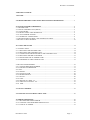
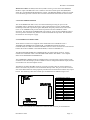
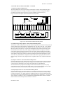
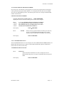
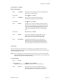
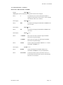
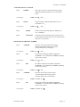
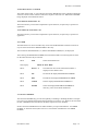
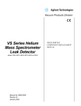
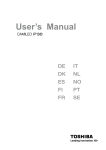
3.2.2 PLS-601 FRONT PANEL USER INTERFACE
The PLS-601 front panel has been designed for ease of use. The front panel utilizes a 16 digit
alphanumeric display, an operating mode selection keyswitch, a positive tactile feel keypad,
and various LED status indicators. Figure 3.2.2 depicts the PLS-601 front panel user interface.
PROG
MODE
PROGRAM
1
P000 - R000
POS/TACH
SET
FUNCTION
DISPLAY
0
ENTER
MASTER
OFFSET
SCALE
MOTION
1
2
3
TEACH
COPY
F7
F8
END
5
6
7
8
9
4
UTILITY
OUTPUT
DISABLE
CURSOR
CURSOR
INC
NEXT
CLEAR
CHANNEL STATUS
GROUP
A B C D
DEC
1
2
3
4
5
6
7
8
9
10
MD
11 12 13 14 15 16
Figure 3.2.2 PLS-601 Front Panel User Interface
Document #11696
Page - 5
PLS-601 User's Manual
3.2.2 PLS-601 FRONT PANEL USER INTERFACE - Continued
Each element of the front panel will be discussed in order to give insight into the operation of the
PLS-601 unit. The description of the front panel elements follows.
Display:The PLS-601 front panel user interface is equipped with a 16 digit alphanumeric display
that is used to inspect and/or program data fields or operating modes of the unit. The display is of
the vacuum fluorescent type which provides bright, easy to see visual feedback even in dimly
lighted areas.
Mode Keyswitch:The mode keyswitch protects the user program data from being changed by
unauthorized personnel, through the provision of three, key-selectable modes of operation. In
Display mode, program data can be displayed and verified, but not changed. In Program mode, all
standard PLS-601 functions can are enabled, allowing the user to enter program data into memory
even while the unit is operating. In Master mode, access is allowed to a set of optional Master
functions that are normally required only during system installation and configuration. The key
can only be removed while the switch is in the display mode position.
Function/Data Keys:
The FUNCTION key is used to select whether the ten dual-purpose function/data keys
are to be used to select one of the PLS-601 functions, or to enter numerical data. By
FUNCTION
pressing the function key, the associated function LED will either turn on to indicate
function entry mode, or turn off to indicate data entry mode. While in data
mode, numerical data 0 through 9 can be entered.
ENTER
POS/TACH
0
SET
1
OFFSET
2
SCALE
3
MOTION
4
The ENTER key is used to enter data into non-volatile EEPROM memory during
execution of the PLS-601 functions. The PLS-601 currently supports the following
functions:
The POS/TACH function is used to display the selected PROGRAM NUMBER (PROG),
the current resolver angle POSITION (P), and the current speed of the resolver shaft in
RPM (R) when the function key is active. In data entry mode, this is the number 0 key.
The SET function is used to enter LOBE data in to the PLS-601 control unit's memory.
Set allows single or multiple lobes to be entered on any or all of the 64 channels. A total
of 3808 LOBES (238 LOBES per channel group per program). In data entry mode, this is
the number 1 key.
The OFFSET function is used to display or enter a positive value that is added to the
actual resolver angle value. This parameter is used to align the resolver zero angle
reference point to the actual machine zero angle reference point. In brief, electrical zero
can be adjusted to match that of mechanical zero through the use of the OFFSET value.
In data entry mode, this is the number 2 key.
The SCALE function is used to display or enter the scale factor parameter into the PLS601 Control Unit's memory. The scale factor is the number of intervals that one complete
resolver rotation is divided into. In data entry mode, this is the number 3 key.
The MOTION function allows the user to set a window for shaft speed. If the resolver
shaft speed falls within the defined window criteria, the MD LED (Motion Detect) and
Motion Detect outputs will provide visual and electrical feedback depending on how the
Motion Detect parameters are programmed into the control unit's memory. In data entry
mode, this is the number 4 key.
Document #11696
Page - 6
PLS-601 User's Manual
3.2.2 PLS-601 FRONT PANEL USER INTERFACE - Continued
TEACH
5
COPY
6
F7
7
F8
8
END
9
The TEACH function allows a user to enter the current shaft position into memory as the
FROM or TO position of a LOBE, using only the ENTER key. In data entry mode, this is
the number 5 key.
The COPY function allows the user to copy the stored program data from one channel to
another, one program to another, or from one PLS-601 control unit to another. In data
entry mode, this is the number 6 key.
The F7 function can be used to implement a special function, as required by a specific
user's application. In data entry mode, this is the number 7 key.
The F8 function can be used to implement a special function, as required by a specific
user's application. In data entry mode, this is the number 8 key.
The END function is used to end data entry for the current program. It also allows for the
selection of the other programs available for data entry. Currently, the number of
programs available is 1 through 4. In data entry mode, this is the number 9 key.
Each of the above functions will be described in detail, later within this manual.
Utility Keys: The utility keys are used in conjunction with the function/data keys to increase the
ease of entering data into the PLS-601 memory. Following is a functional description of each.
CURSOR
CURSOR
INC
DEC
NEXT
CLEAR
OUTPUT
DISABLE
CURSOR KEYS are used to move the cursor within the various PLS-601 data
fields, allowing the user to select only those positions at which data entry or data
modification is desired.
The INC and DEC keys are used to modify existing user data by either
INCrementing or DECrementing the selected data field.
The NEXT key is used to display the sequence of user LOBE data for the SET
and TEACH functions. The CLEAR key is used with several of the PLS-601
functions to set a data field to a pre-defined value such as zero.
The OUTPUT DISABLE key provides the capability of enabling or disabling the relay
outputs of the remote relay output board. When the LED is active, the output relays are
disabled. Take note that the channel and motion detect output indicators located on the
PLS-601 control unit will continue to display output status even though the outputs are
turned off.
Group and Channel Status LEDs: The GROUP and CHANNEL LEDs are used in conjunction
with each other to give the status of the sixty-four independent channel outputs. The channel
outputs are divided into four groups designated as A, B, C, and D. Each group contains sixteen
channel outputs. The channel outputs per group are represented as channels A01-A16, B01-B16,
C01-C16, and D01-D16. The active group LED designate the active channel outputs.
Document #11696
Page - 7
PLS-601 User's Manual
Motion Detect LED: The MD (motion detect) LED is used to give the status of the MOTION
DETECT output. The MD LED is active whenever the resolver shaft speed value (RPM) falls
within the programmed MOTION DETECT window. The MOTION DETECT output is brought
out to the twenty pin male connector that is located on the bottom of the PLS-601 Control Unit.
3.2.4 AC/DC POWER SYSTEM
The AC POWER PLUG offers a safe, convenient method of providing AC power to the
CONTROL UNIT - eliminating the need to connect individual power wires. An RFI LINE
FILTER provides built in protection against RFI (Radio Frequency Interference) induced line
noise. An AC POWER FUSE provides electrical protection for the CONTROL UNIT’s
electronics. The internal DC POWER SUPPLY provides DC power for the CONTROL UNIT as
well as up to four solid state relay boards or one electromechanical relay board. This eliminates
the need for an external power supply.
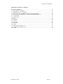
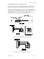
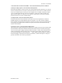
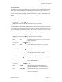
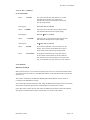
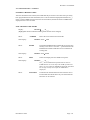
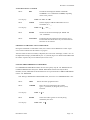
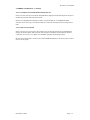
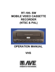
3.2.5 INTERFACE CONNECTORS
Three interface connectors are supplied on the standard PLS-601 CONTROL UNIT: a
TRANSDUCER INTERFACE CONNECTOR, a COMMUNICATIONS OUTPUT
CONNECTOR, and a RELAY OUTPUT BOARD connector. These connectors are located on the
bottom side of the CONTROL UNIT ENCLOSURE, as shown in FIGURE 3.2.5.
The TRANSDUCER INTERFACE CONNECTOR is an eight-pin male connector, used to
interface the CONTROL UNIT to the TRANSDUCER. Refer to SECTION 3.3 for complete
details on the TRANSDUCER INTERFACE.
The COMMUNICATIONS OUTPUT CONNECTOR is a four-pin male connector that provides
serial data to the remote display. If the CONTROL UNIT is configured for RS232 output, the data
can interface to an external computer or PLC.
The RELAY OUTPUT BOARD connector is a twenty pin male connector used to interface to
either a solid state relay board or an electromechanical relay board. The pin-out of this connector
will not be detailed because of the proprietary interface between the PLS-601 and the relay output
boards. The remaining connectors and their pin-out definitions are defined in Figure 3.2.5.
Communications Connector
Pin 1
Ground
Pin 2
RD
Pin 3
TD
Pin 4
CTL1
Resolver Interface Connector
Pin 1
No connection
Pin2
No connection
Pin 3
S1 (Stator 1)
Pin 4
S3 (Stator 3)
Pin 5
S4 (Stator 4)
Pin 6
S2 (Stator 2)
Pin 7
R2 (Rotor 2)
Pin 8
R1 (Rotor 1)
Figure 3.2.5 Bottom view of PLS-601 control unit and connector pin-out definitions.
Document #11696
Page - 8
PLS-601 User's Manual
3.3 TRANSDUCER/CONTROL UNIT INTERFACE CABLE
The CONTROL UNIT is interfaced to the TRANSDUCER via a custom made transducer
interface cable. This cable consist of three individually shielded pairs, that has an eight pin female
plug-connector on one end, and a seven pin female MS-type connector on the other end.
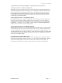
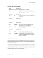
The standard transducer interface cable is wired at the factory to provide an INCREASING
angular position reading for CLOCKWISE rotation of the TRANSDUCER shaft (when looking
into the END of the shaft). The wiring diagram for this cable is shown in Figure 3.3A.
If an INCREASING angular position reading for COUNTER CLOCKWISE rotation of the
TRANSDUCER shaft is desired, refer to Figure 3.3B for that wiring diagram.
Figure 3.3A
Standard Wiring Diagram (Clockwise transducer shaft rotation)
Figure 3.3B
Wiring Diagram (Counter clockwise transducer shaft rotation)
Document #11696
Page - 9
B
A
PLS-601 User's Manual
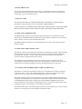
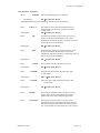
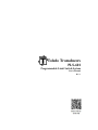
3.4 PLS-601 RELAY OUTPUT BOARDS
0
0
The PLS-601 is available with solid state or electromechanical relay boards. Each relay board can
contain up to seventeen relays. Sixteen of these relays are dedicated for channel outputs. The
remaining relay is dedicated to the MOTION DETECT output. A maximum of four relay boards
can be interfaced to the control unit, providing a total of sixty-four relay outputs.
0
0
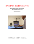
3.4.1 Solid State Relay Board
The solid state relay board is available with four different types of relays. These relays are as
follows:
• 120 VAC at 3 Amps
• 240 VAC at 3 Amps
• 60 VDC at 3 Amps
• 200 VDC at 1 Amp
1
1
All solid state relays are optically isolated and individually fused for safe, reliable operation. Each
relay also has an associated LED to indicate its ON/OFF status. An additional feature of the PLS601, is that the internal power supply can drive up to four fully loaded solid state relay boards.
This eliminates the need for an external power supply.
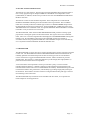
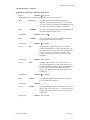
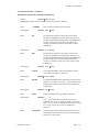
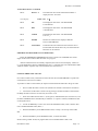
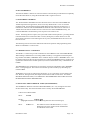
Figure 3.4.1 shows the layout of the solid state relay board.
1
16 ERR
Interface Connectors
D C B A D C B A
H H H H L L L L
4
A
B
C
D
Relay 16 Jumper
P101
1
MD
1
2
3
4
5
6
7
8
9
10
11
2
12
3
P
INT EXT
ENABLE
2
Channel Group Jumpers
P
1 2 3
I
1 2 3
P102
4
5
13
1
14
2
3
15
4
5
16
5
3
Output Enable
Connector
Relay Output Connectors
+1 - +2 - +3 - +4 -
+5 - +6 - + 7 - +8 -
+ 9 - +10- +11 - +12-
+13- +14 - +15- + 16N
+MD-
ENA
Figure 3.4.1 PLS-601 Solid State Relay Board
P
(1) Channel Group Jumper Options - Solid State Relay Board
The PLS-601 control unit provides sixty-four channel outputs that are divided into four groups of
sixteen channels each. The channels are designated as A01-A16, B01 - B16, C01 - C16, and D01D16. Up to four solid state relay boards, each with sixteen output relays can be attached to the
PLS-601 control unit. Each board must be assigned to one of four output groups designated as A,
B, C, or D. This is done by installing the two channel group jumpers in the proper positions on the
relay board (see "Channel Group Jumpers" in Figure 3.4.1). The solid state relay board must be
configured to match the PLS-601 output group that will drive it. Output Group A will drive relay
output board A, Group B will drive relay output board B and so forth.
Document #11696
Page - 10
PLS-601 User's Manual
3.4 PLS-601 RELAY OUTPUT BOARDS - Solid State Relay Board Continued
(2 Interface Connectors) - Solid State Relay Board
Each solid state relay output board contains two 20 pin male interface connectors labeled P101A
and P101B (see Interface Connectors in Figure 3.4.1). The PLS-601 Control Unit will connect to
P101A through the use of a twenty pin ribbon cable. To add additional solid state relay output
boards, simply connect P101B of the first (or previous) relay output board to P101A of the next
relay output board. Up to four solid state relay output boards can be connected to the PLS-601
Control Unit by this interface method.
(3) Relay Output Connectors - Solid State Relay Board
Each solid state relay board contains four 8 pin plug connectors that provides two output pins for
each of the sixteen channels (see Relay Output Connectors in Figure 3.4.1). These outputs are
normally off until activated by the PLS-601 Control Unit. The solid state relay output connectors
are labeled (+ 1 -) through (+ 16 -). In addition, a 2 pin connector is available for the MOTION
DETECT function. This connector is labeled (+ MD -).
(4) Relay 16 Jumper Options - Solid State Relay Board
Solid state Relay 16 may be used as one of the standard channel output relays, or it may be used as
an indication that an error has occurred in the PLS-601 Control Unit. To enable solid state Relay
16 as a standard output, connect pins 1 and 2 together of J1 (see Relay 16 Jumper in Figure 3.4.1).
To enable solid state relay 16 as an error indicator, connect pins 2 and 3 together of J1. When solid
state relay 16 is used as an error indicator, it will be active in non error conditions (ON) and nonactive in an error condition (OFF).
(5) Output Enable - Solid State Relay Board
Each solid state relay board has a 2 pin input connector that implements an OUPTUT ENABLE
function (see Output Enable Connector in Figure 3.4.1). This connector is labeled ENA. The ENA
pins must be shorted together in order for any of the seventeen solid state relay outputs to be
enabled. If this connection is opened, all seventeen solid state relay outputs will be disabled.
Document #11696
Page - 11
0
0
P
PLS-601 User's Manual
3.4 PLS-601 RELAY OUTPUT BOARDS - Continued
1
N
1
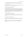
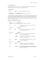
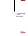
3.4.2 Electromechanical Relay Board
The electromechanical relay board contains a maximum of seventeen electromechanical relays,
each rated at 240 VAC at 10 Amps, or 30VDC at 10Amps. Each relay is configured as SPST,
providing one normally open contact (N.O.) and one normally closed contact (N.C.).
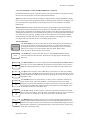
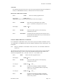
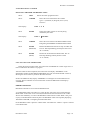
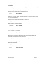
Figure 3.4.2 shows the layout of the electromechanical relay board.
1
2
Channel Group Jumpers
Interface Connectors
16 ERR
INT EXT
+12VDC
D C B A D C B A
H H H H L L L L
C
P
I
B
D
DC Power Source
4
P
A
6
P101
P102
Relay 16 Jumper
1
1
2
+
12DC
3
4
5
6
7
8
9
10
5
3
Output Enable
Connector
Relay Output Connectors
ENA
NO C NC NO C NC
MD
1
NO
C
3
NC
NO C NC NO C NC
2
4
NO
C NC
6
NO C NC NO C NC
5
7
NO
C
9
NC
NO C NC NO C NC
8
10
2
11
NO
3
4
12
C NC
12
NO C NC NO C NC
11
13
5
1
2
3
13
NO
4
14
5
15
16
C NC
15
NO C NC NO C NC
14
16
MD
Figure 3.4.2 PLS-601 Electromechanical Relay Board
(1) Channel Group Jumper Options - Electromechanical Relay Board
The PLS-601 Control Unit provides sixty-four channel outputs that are divided into four groups of
sixteen channels each. The channels are designated as A01-A16, B01 - B16, C01 - C16, and D01D16. Up to four electromechanical relay boards, each with sixteen relays, can be attached to the
PLS-601 Control Unit. However, only one electromechanical relay board can be directly driven
from the PLS-601 Control Unit’s power supply. If additional boards are required, an external
power supply must be used (see DC Power Source for details). Each board must be assigned to
one of four output groups designated as A, B, C, or D. This is done by installing the two channel
group jumpers in the proper positions on the relay board (see Channel Group Jumpers in Figure
3.4.2). The relay board must be configured to match the PLS-601 output group that will drive it.
Output Group A will drive relay output board A, Group B will drive relay output board B and so
forth.
(2) Interface Connectors - Electromechanical Relay Board
Each electromechanical relay output board contains two 20 pin male interface connectors labeled
P101A and P101B (see Interface Connectors in Figure 3.4.2). The PLS-601 Control Unit will
connect to P101A through the use of a twenty pin ribbon cable. To add additional
electromechanical relay output boards, simply connect P101B of the first (or previous) relay
output board to P101A of the next relay output board. Up to four electromechanical relay output
boards can be connected to the PLS-601 Control Unit by this interface method.
(3) Relay Output Connectors - Electromechanical Relay Board
Each electromechanical relay board contains five 3 pin plug connectors and six 6 pin connectors
that provides two output pins and a common for each of the sixteen channels (see Relay Output
Connectors in Figure 3.4.2). These outputs are normally closed (NC) until activated by the PLS601 Control Unit. The electromechanical relay output connectors are labeled (NO C NC) for each
of the channels. In addition, 3 pins are available for the MOTION DETECT function. The MD
function shares the first three pins of the channel 1 connector.
Document #11696
Page - 12
PLS-601 User's Manual
3.4 PLS-601 RELAY OUTPUT BOARDS - Electromechanical Relay Board Continued
(4) Relay 16 Jumper Options - Electromechanical Relay Board
Electromechanical Relay 16 may be used as one of the standard channel output relays, or it may be
used as an indication that an error has occurred in the PLS-601 Control Unit. To enable solid state
relay 16 as a standard output, connect pins 1 and 2 together of J1 (see Relay 16 Jumper in Figure
3.4.2). To enable solid state relay 16 as an error indicator, connect pins 2 and 3 together of J1.
When solid state Relay 16 is used as an error indicator, it will be active in non error conditions
(ON) and non-active in an error condition (OFF).
(5) Output Enable - Electromechanical Relay Board
Each electromechanical relay board has a 2 pin input connector that implements an OUPTUT
ENABLE function (see "Output Enable Connector in Figure 3.4.2). This connector is labeled
ENA. The ENA pins must be shorted together in order for any of the seventeen electromechanical
relay outputs to be enabled. If this connection is opened, all seventeen electromechanical relay
outputs will be disabled.
(6) DC Power Source - Electromechanical Relay Board
The internal power supply of the PLS-601 Control Unit is capable of only driving one fully loaded
electromechanical relay board. Additional boards must be driven from an external power supply.
To use an external power supply, the jumper labeled INT EXT +12VDC must be placed between
2 and 3 (see DC Power Source in Figure 3.4.2). The external power supply voltage source must
enter the board through the connector labeled (+ - 12DC). Make sure that the positive voltage of
the external supply is attached to the connector pin labeled (+) and that the negative voltage (or
ground) is attached to the connector pin labeled ‘-‘.
Document #11696
Page - 13
PLS-601 User's Manual
4.0 USING THE PLS-601
It is strongly recommended that this portion of the User’s Manual be read in its entirety before
placing your PLS-601 into operation. Failure to follow the instructions given in the following
sections may void your PLS-601 warranty.
4.1 INSTALLATION
ALL PLS-601 ELECTRICAL CONNECTORS MUST CONFORM TO THE NATIONAL
ELECTRIC CODE AND ANY LOCAL ELECTRIC CODES IN EFFECT.
IN THE CASE OF ANY DISCREPANCIES BETWEEN THE ELECTRIC CODES AND THESE
INSTALLATION INSTRUCTIONS, THE ELECTRIC CODE MUST TAKE PRECEDENT.
4.1.1 MOUNTING THE RESOLVER
The RESOLVER is designed to be mounted on the target machine, and coupled to the target
machine shaft. The RESOLVER should be mounted and coupled in a manner such as to minimize
shock, vibration, as well as axial and radial shaft loading.
The RESOLVER may be mounted via the standard front face mount or the optional foot-type
mounting adapter.
4.1.2 MOUNTING THE CONTROL UNIT
The PLS-601 Control Unit is designed to be mounted in a NEMA type enclosure, which is suitable
for the ambient environment. The enclosure must protect the Control Unit from contamination
caused by water, oil, dust, or corrosive gases. The Control Unit should not be subjected to
excessive amount of mechanical shock or vibration.
The mounting location should be chosen such as to avoid exposure to significant levels of
electromagnetic interference (EMI), which can be induced by devices such as motor starters and
control relays. The operating temperature must be maintained between 32°F and 125°F.
4.1.3 CONNECTING THE RESOLVER TO THE CONTROL UNIT
The Resolver is connected to the PLS-601 Control Unit via the Resolver/Control Unit Interface
Cable. The Cable is a 3-pair, individually shielded cable, containing an eight pin female plugconnector on one end, and a seven pin female MS-type connector on the other.
The standard interface cable is wired at the factory to provide an INCREASING angular position
reading for CLOCKWISE rotation of the Resolver shaft (when looking into the END of the shaft).
An INCREASING angular position reading during COUNTERCLOCKWISE rotation of the
Resolver shaft may be achieved by interchanging two of the wires that are brought into the eight
pin female connector. See SECTION 3.3 for complete wiring details.
The interface cable may be a maximum length of 2500 feet, and should always be routed in such a
manner as to avoid exposure to electromagnetic interference (EMI).
Document #11696
Page - 14
PLS-601 User's Manual
4.1.3 CONNECTING THE RESOLVER TO THE CONTROL UNIT - Continued
The seven pin female MS-connector is plugged into the mating seven pin male connector located
on the rear of the Resolver.
The eight pin female connector is plugged into the mating eight pin male connector located on the
bottom of the PLS-601 Control Unit (See SECTION 3.2.5).
4.1.4 MOUNTING THE RELAY BOARDS
The relay boards are designed to be mounted in a NEMA type enclosure that is suitable for the
environment that the boards will operate within. The enclosure must be shock mounted and be
able to protect the boards from water, oil, dust, and corrosive materials. The boards should not be
exposed to excessive amounts of mechanical shock or vibration. The mounting location should not
be exposed to extreme levels of electromagnetic interference (EMI) that can be induced by
devices such as motor starters and control relays. The operating temperature of the relay boards
has been rated at 32°F to 125°F.
4.1.5 INSTALLING THE AC POWER CORD
An AC Power Cord is provided with each PLS-601 Control Unit. The female end of the Power
Cord should be inserted into the male AC Power Plug located on the side of the Control Unit
enclosure.
4.1.6 POWERING ON THE CONTROL UNIT
The Control Unit requires a clean, stable source of AC Power to operate. See SECTION 3.2 for
the complete AC Power requirements and specifications of the various Control Unit input power
options.
The male end of the AC Power Cord should be inserted into a standard GROUNDING
RECEPTACLE, which has been wired to provide the AC Power requirements specified in
SECTION 3.2.
Document #11696
Page - 15
PLS-601 User's Manual
4.2 PLS-601 PROGRAMMING
The PLS-601 Control Unit offers four standard programs, each consisting of OFFSET, SCALE
FACTOR, MOTION DETECT, and LOBE data that is entered by the user via the PLS-601
functions. The SCALE FACTOR, OFFSET, SETPOINT and MOTION DETECT functions
require the user to enter data via the FRONT PANEL. Parameters can only be entered into the
PLS-601 memory when the front panel mode switch is in the PROGRAM position.
The following sections explain how to enter data into the control unit. A typical programming
sequence for the PLS-601is as follows:
• Apply power to the PLS-601 control unit.
• Turn mode switch to PROGRAM
• Enter SCALE values
• Enter OFFSET values
• Enter SET mode or "TEACH" mode
• Define MOTION detect window
• Perform COPY command if applicable
• END programming sequence
For each of the PLS-601 functions, a BLINKING digit on the display indicates the position of the
cursor at which data may be entered. Once programmed, the user may quickly and easily instruct
the unit to operate under the control of any one of the four separate programs. Figure 4.2.1 depicts
the front panel of the PLS-601 control unit.
PROG
MODE
PROGRAM
1
P000 - R000
POS/TACH
SET
FUNCTION
DISPLAY
0
ENTER
MASTER
OFFSET
SCALE
MOTION
1
2
3
TEACH
COPY
F7
F8
END
4
5
6
7
8
9
UTILITY
OUTPUT
DISABLE
CURSOR
CURSOR
INC
NEXT
GROUP
A B C D
DEC
CLEAR
CHANNEL STATUS
1
2
3
4
5
6
7
8
9
10
MD
11 12 13 14 15 16
Figure 4.2.1 PLS-601 Front Panel
Document #11696
Page - 16
PLS-601 User's Manual
4.2.1 PLS-601 CHANGE PROGRAM NUMBER
Once the power to the PLS-601 has been applied, one of the four programs must be selected by
entering the desired program number (PROG). To accomplish this task, make sure the MODE
switch is in the ‘PROGRAM’ position. The following describes how to change the PROGRAM
number of the PLS-601.
CHANGE PROGRAM NUMBER:
CHANGE PROGRAM NUMBER DISPLAY: PROG 1 P000-R000
(Highlighted character indicates blinking character that can be changed)
Select:
or Select:
or Select
or Select
1 2 3 or 4 (Blinking character will change accordingly)
INC (Blinking character will INCrement to next value)
DEC (Blinking character will DECrement to next value)
CLEAR (Selects PROGRAM NUMBER 1)
New Display:
Select:
PROG 2 P000-R000
ENTER
Selects the new program number into memory for data entry
to begin. The FUNCTION LED becomes active and the
display prompt for PROGRAM NUMBER stops blinking.
New Display:
PROG 2 P000-R000
4.2.2 TACHOMETER Function
The TACHOMETER function is used to display the selected PROGRAM NUMBER (PROG), the
RESOLVER shaft position (P) in degrees, and the RESOLVER shaft speed (R) in RPM. This
function does not allow for data entry.
TACHOMETER DATA Function:
Select:
POS/TACH
Selects the POS/TACH function in order to display the current
RESOLVER shaft position in degrees and RESOLVER shaft speed in
RPM.
New Display:
Document #11696
PROG 2 P000-R000
Page - 17
PLS-601 User's Manual
4.2.3 SET Function
The SET function is used to enter LOBE data into the PLS-601’s memory. The SET function will
allow single or multiple LOBE data to be entered on any or all of the 64 available channels. A
total of 3808 LOBES (238 LOBES per channel group per program) may be entered. The timing
and dwell of each LOBE is defined by a FROM position and a TO position. The FROM position
defines the timing, whereas the difference between the FROM and TO positions defines the
DWELL.
SET Function:
Select:
SET
Selects the LOBE data entry function.
New Display:
CH A01 F -T
(Highlighted character indicates blinking character that can be changed.)
To enter LOBE data, the CHANNEL GROUP must be selected. Once the channel group has been
chosen, the desired channel within the group must be selected. The channels are divided into four
groups with each group consisting of up to sixteen channels. When all channel groups are active, a
total of 64 individual channels become available. The channels are designated as A01 - A16, B01 B16, C01 - C16, and D01 - D16.
SELECTING THE CHANNEL GROUP:
Display:
CH A01 F -T
(Highlighted character indicates blinking character that can be changed)
Select:
INC
Increments the active group (A, B, C, or D) to the next
available group value.
New Display:
Select:
CH B01 F -T
DEC
New Display:
Select:
New Display:
Select:
Decrements the active group (A, B, C, or D) to the
previous available group value.
CH A01 F -T
CURSOR
Moves the cursor left or right within the three digit
CHANNEL field of the front panel display.
CH A01 F -T
> key used to move CURSOR to the RIGHT.
CH A01 F -T
< key used to move CURSOR to the LEFT.
CLEAR
New Display :
Sets the displayed CHANNEL GROUP to "A" and the
CHANNEL NUMBER to "1".
CH A01 F -T
Select:
ENTER
Selects the displayed CHANNEL GROUP and
CHANNEL NUMBER for entry of LOBE DATA.
Select:
FUNCTION:
Terminates the SET function and returns the user to
FUNCTION select mode where any one of the PLS-601
functions can be selected.
Document #11696
Page - 18
PLS-601 User's Manual
4.2.3 SET Function - Continued
SELECTING THE CHANNEL NUMBER:
Display:
CH A01 F -T
(Highlighted character indicates blinking character that can be changed)
Select:
2
New Display:
Select:
CH A02 F -T
DEC
New Display:
Select:
The numerical value of the selected DATA KEY is
displayed in the present cursor position. In this example,
the numerical value of 2 is selected.
Decrements the displayed CHANNEL NUMBER to the
previous value.
CH A01 F -T
INC
New Display:
Increments the displayed CHANNEL NUMBER to the
next value.
CH A02 F -T
Select:
CURSOR
Moves the cursor left or right within the three digit
CHANNEL field of the front panel display.
Select:
CLEAR
Sets the displayed CHANNEL GROUP to "A" and the
CHANNEL NUMBER to "1".
New Display :
CH A01 F -T
Select:
ENTER
Selects the displayed CHANNEL GROUP and
CHANNEL NUMBER for entry of LOBE DATA.
Select:
FUNCTION:
Terminates the SET function and returns the user to
FUNCTION select mode where anyone of the PLS-601
functions can be selected.
ENTERING CHANNEL LOBES
After the channel has been selected, the LOBE data may be entered. If no lobes have previously
been programmed for the selected channel, the F and T fields will display blank characters (‘_’).
If one or more LOBES already exist for the selected channel, the data for the first LOBE will be
displayed in the F and T fields.
The PLS-601 allows programming through zero by specifying a FROM field that is larger than the
TO field. For example, if the ‘FROM’ field is specified as 300 and the TO field is set to 060, the
channel output will turn on at 300, remain on through zero, and turn off at 060. The PLS-601 will
not allow data entry into the FROM or TO fields if the value is greater than the SCALE FACTOR
value. If this is attempted, the value will automatically be set to zero.
The following designates the entry of new channel LOBES.
Document #11696
Page - 19
PLS-601 User's Manual
4.2.3 SET Function - Continued
NEW CHANNEL LOBE ENTRY
Display:
CH A01 F_ _ _ -T_ _ _
(Highlighted character indicates blinking character that can be changed)
Select:
DATA 0 - 9
New Display:
Select:
CHA01 F 1 2 3 - T 3 4 5
< CURSOR
New Display:
Select:
>CURSOR
New Display:
Select:
Document #11696
Moves the cursor right within the three digit FROM or
TO data fields of the front panel display.
CHA01 F 1 2 3 - T 3 4 5
ENTER
New Display:
Select:
Moves the cursor left within the three digit FROM or TO
data fields of the front panel display.
CHA01 F 1 2 3 - T 3 4 5
New Display:
Select:
The numerical value of the selected DATA KEY is
displayed in the present cursor position. As an example,
the value of 123 will be entered into the FROM field and
the value of 345 will be entered into the TO field.
The displayed FROM and TO data fields are entered into
memory. The cursor is set to the ‘-‘ position between the
FROM and TO fields and the data is now considered as
existing data.
CHA01 F 1 2 3 - T 3 4 5
NEXT
Selects and displays the next LOBE in sequence.
CHA02 F _ _ _ - T_ _ _
The '_' in the FROM and TO fields indicates that no
LOBE data has been stored for this LOBE. If numerical
data is present within the FROM and TO fields, than data
has been previously entered for the LOBE that is
displayed.
FUNCTION:
Terminates the SET function and returns the user to
FUNCTION select mode where anyone of the PLS-601
functions can be selected.
Page - 20
PLS-601 User's Manual
4.2.3 SET Function - Continued
MODIFYING EXISTING CHANNEL LOBE DATA
Display:
CH A01 F 1 2 3 - T 3 4 5
(Highlighted character indicates blinking character that can be changed)
Select:
DATA 0 - 9
The numerical value of the selected DATA KEY is
displayed in the present cursor position. As an example,
the value of 123 will be entered into the FROM fie ld and
the value of 345 will be entered into the TO field.
Select:
< CURSOR
Moves the cursor left within the three digit FROM or TO
data fields of the front panel display.
New Display:
Select:
CHA01 F 1 2 3 - T 3 4 5
>CURSOR
New Display:
Select:
CHA01 F 1 2 3 - T 3 4 5
INC
New Display:
Select:
DEC
New Display:
Document #11696
Decrements the numerical value at the current cursor
location in the FROM or TO data fields. If the cursor is
between the FROM and TO data fields, both FROM and
TO data values will be decremented and placed into
memory. The DEC key does not require the use of the
ENTER key.
CHA01 F 1 2 3 - T 3 4 5
CLEAR
New Display:
Select:
Increments the numerical value at the current cursor
location in the FROM or TO data fields. If the cursor is
between the FROM and TO data fields, both FROM and
TO data values will be incremented and placed into
memory. The INC key does not require the use of the
ENTER key.
CHA01 F 2 2 3 - T 3 4 5
New Display:
Select:
Moves the cursor right within the three digit FROM or
TO data fields of the front panel display.
The displayed LOBE is erased from memory allowing
for new LOBE data to entered.
CHA01 F _ _ _ - T _ _ _
ENTER
The displayed FROM and TO data fields are entered into
memory. The cursor is set to the ‘-‘ position between the
FROM and TO fields and the data is now considered as
existing data.
CHA01 F 1 2 3 - T 3 4 5
Page - 21
PLS-601 User's Manual
4.2.3 SET Function - Continued
MODIFYING EXISTING CHANNEL LOBE DATA
Select:
NEXT
New Display:
Select:
Selects and displays the next LOBE in sequence.
CHA02 F _ _ _ - T_ _ _
The '_' in the FROM and TO fields indicates that no
LOBE data has been stored for this LOBE. If numerical
data is present within the FROM and TO fields, than data
has been previously entered for the LOBE that is
displayed.
FUNCTION:
Terminates the SET function and returns the user to
FUNCTION select mode where anyone of the PLS-601
functions can be selected.
4.2.4 OFFSET
The OFFSET is a constant, positive adjustment that the CONTROL UNIT adds to the actual
Resolver position to produce the shaft POSITION which is displayed and used by the Control Unit
functions. The OFFSET function allows the user to align the resolver (electrical zero) and machine
(mechanical zero) reference points.
The permissible value of the OFFSET parameter is in the range from 0 to the FULL SCALE
VALUE.
An AUTO ZERO function is implemented via the CLEAR key that will automatically calculate
the offset required to zero the current resolver shaft position. Using this function will electrically
set the position of the resolver to 000 within the position field (P) on the PLS-601 front panel
display.
NOTE: Changing the OFFSET value causes a corresponding change in the displayed shaft
POSITION, but does not affect the values of the stored LOBE data.
The OFFSET function will display the current resolver shaft position within the ‘P’ data field and
the current resolver shaft rotational speed in RPM within the ‘R’ data field.
RESOLVER OFFSET:
Select:
OFFSET
OFFSET DISPLAY:
OF 0 0 0 P 0 7 5 - R 0 4 0
(Highlighted character indicates blinking character that can be changed)
Select:
DATA 0 - 9
The numerical value of the selected DATA KEY is
displayed in the present cursor position of the OFFSET
data field.
Select:
INC
Increments the OFFSET value on the display.
New Display:
OF 0 0 1 P 0 7 5 - R 0 4 0
Select:
Decrements the OFFSET value on the display.
DEC
New Display:
Document #11696
OF 0 0 0 P 0 7 5 - R 0 4 0
Page - 22
PLS-601 User's Manual
4.2.4 OFFSET - Continued
RESOLVER OFFSET:
Select:
< CURSOR
Moves the cursor left within the three digit OFFSET data
field of the front panel display.
New Display:
OF 0 0 0 P 0 7 5 - R 0 4 0
Select:
Moves the cursor right within the three digit
OFFSET data field of the front panel display.
>CURSOR
New Display:
OF 0 0 0 P 0 7 5 - R 0 4 0
Select:
The PLS-601 control unit calculates, displays and stores
the offset value required to set the resolver shaft position
to electrical '000'. When the CLEAR function is used, the
offset value is calculated and placed into memory. This
function will terminate the data entry for the OFFSET
value.
CLEAR
New Display:
OF 0 0 0 P 0 7 5 - R 0 4 0
Select:
ENTER
Stores the new OFFSET value into memory on the
display. The Control Unit automatically returns to
FUNCTION select mode after pressing ENTER.
Select:
FUNCTION:
Pressing the FUNCTION key at any time while in
OFFSET mode will terminates the OFFSET function
and returns the user to FUNCTION select mode where
any one of the PLS-601 other functions can be selected.
4.2.5 SCALE
The SCALE FACTOR is the number of increments that the CONTROL UNIT divides one
complete Transducer shaft rotation into. The SCALE function allows the user to enter a SCALE
FACTOR FROM 0002 TO 1000.
NOTE: Upon changing the SCALE FACTOR, the Control Unit will re-scale all stored LOBE
data. Care should be taken when changing the SCALE FACTOR, as the rescaling of the
LOBE data may produce undesirable rounding.
SCALE FACTOR:
Select:
SCALE
SCALE DISPLAY:
SF 1 0 0 0 P 0 7 5 - R 0 4 0
(Highlighted character indicates blinking character that can be changed)
Select:
DATA 0 - 9
Document #11696
The numerical value of the selected DATA KEY is
displayed in the present cursor position of the SCALE
FACTOR data field - to a maximum value of 1000.
Page - 23
PLS-601 User's Manual
4.2.5 SCALE - Continued
SCALE FACTOR:
Select:
CLEAR
The value of the SCALE FACTOR is set to 1000
and entered into memory. The Control Unit
automatically returns to FUNCTION select mode
after pressing CLEAR.
New Display:
SF 1 0 0 0 P 0 7 5 - R 0 4 0
Select: < CURSOR
Moves the cursor left within the four digit SCALE
FACTOR data field of the front panel display.
New Display:
SF 1 0 0 0 P 0 7 5 - R 0 4 0
Select:
Moves the cursor right within the four digit SCALE
FACTOR data field of the front panel display.
> CURSOR
New Display:
SF 1 0 0 0 P 0 7 5 - R 0 4 0
Select:
ENTER
Stores the new OFFSET value into memory on the
display. The Control Unit automatically returns to
FUNCTION select mode after pressing ENTER.
Select:
FUNCTION:
Pressing the FUNCTION key at any time while in
SCALE mode will terminates the SCALE function
and returns the user to FUNCTION select mode where
any one of the PLS-601 other functions can be selected.
4.2.6 MOTION
MOTION WINDOW
Motion allows the user to set a window for shaft speed, and receive an indication that the shaft
speed falls within the window via the MD (Motion Detect) LED and Motion Detect output (See
section 3.2.5).
The window is defined by the MOTION FROM (MF) and MOTION TO (MT) values are
considered to be WITHIN the window.
Note: If the ‘MF’ field is less than the ‘MT’ field, the MD LED and output will be ON when the
shaft speed is within the MD window, and OFF when it is outside of the window.
If the ‘MF’ field is greater than the ‘MT’ field, the MD LED and output will be OFF when the
shaft speed is within the MD window, and ON when it is outside of the window.
Document #11696
Page - 24
PLS-601 User's Manual
4.2.6 MOTION - Continued
Select:
MOTION
Selects the MOTION data entry function.
New Display:
MF 0 1 0 MT 0 6 0 - R 0 4 0
(Highlighted character indicates blinking character that can be changed.)
Select:
DATA 0 - 9
New Display:
Select:
INC
New Display:
Select:
Increments the numerical value at the current cursor
location in the MF or MT data fields. The value is
immediately entered into memory, the INC key does not
require the use of the ENTER key.
MF 0 1 0 MT 0 6 0 - R 0 4 0
DEC
New Display:
Select:
The numerical value of the selected DATA KEY is
displayed in the present cursor position of the ‘MF’
or ‘MT’ fields.
MF 0 1 0 MT 0 6 0 - R 0 4 0
Decrements the numerical value at the current cursor
location in the MF or MT data fields. The value is
immediately entered into memory, the DEC key does not
require the use of the ENTER key.
MF 0 1 0 MT 0 6 0 - R 0 4 0
CLEAR
Sets the “MF” and “MT” RPM values to 000
New Display:
MF 0 0 0 MT 0 0 0 - R 0 4 0
Select:
Moves the cursor left within the three digit ‘MF’
or ‘MT’ fields.
< CURSOR
New Display:
MF 0 1 0 MT 0 6 0 - R 0 4 0
Select:
Moves the cursor right within the three digit ‘MF’
or MT fields.
> CURSOR
New Display:
MF 0 1 0 MT 0 6 0 - R 0 4 0
Select:
ENTER
Stores the new MOTION value into memory on the
display. The Control Unit automatically returns to
FUNCTION select mode after pressing ENTER.
Select:
FUNCTION:
Pressing the FUNCTION key at any time while in
MOTION mode will terminate the MOTION function
and returns the user to FUNCTION select mode where
any one of the PLS-601 other functions can be selected.
Document #11696
Page - 25
PLS-601 User's Manual
4.2.7 TEACH Function
The TEACH function allows a user to enter the CURRENT SHAFT POSITON into memory as
the FROM or TO position of a LOBE - using only the ENTER key.
TEACH Function:
Select:
TEACH
Selects the TEACH data entry function.
New Display:
CH A01 F -T
(Highlighted character indicates blinking character that can be changed.)
To enter LOBE data, the CHANNEL GROUP must be selected. Once the channel group has been
chosen, the desired channel within the group must be selected. The channels are divided into four
groups with each group consisting of up to sixteen channels. When all channel groups are active, a
total of 64 individual channels become available. The channels are designated as A01 - A16, B01 B16, C01 - C16, and D01 - D16.
SELECTING THE CHANNEL GROUP:
Display:
CH A01 F -T
(Highlighted character indicates blinking character that can be changed)
Select:
INC
New Display:
Select:
CH B01 F -T
DEC
New Display:
Select:
Select:
Increments the active group (A, B, C, or D) to the next
available group value.
Decrements the active group (A, B, C, or D) to the
previous available group value.
CH A01 F -T
< CURSOR
Moves the cursor left in the three digit CHANNEL
field of the front panel display.
>CURSOR
Moves the cursor right in the three digit CHANNEL
field of the front panel display.
CLEAR
Sets the displayed CHANNEL GROUP to ‘A’ and the
CHANNEL NUMBER to ‘1’.
New Display :
CH A01 F -T
Select:
ENTER
Selects the displayed CHANNEL GROUP and
CHANNEL NUMBER for entry of LOBE DATA.
Select:
FUNCTION:
Terminates the TEACH function and returns the user to
FUNCTION select mode where any one of the PLS-601
functions can be selected.
Document #11696
Page - 26
PLS-601 User's Manual
4.2.7 TEACH Function - Continued
SELECTING THE CHANNEL NUMBER:
Display:
CH A01 F -T
(Highlighted character indicates blinking character that can be changed)
Select:
2
New Display:
Select:
CH A02 F -T
DEC
New Display:
Select:
Select:
Decrements the displayed CHANNEL NUMBER to the
previous value.
CH A01 F -T
INC
New Display:
Select:
The numerical value of the selected DATA KEY is
displayed in the present cursor position. In this example,
the numerical value of 2 is selected.
Increments the displayed CHANNEL NUMBER to the
next value.
CH A02 F -T
< CURSOR
Moves the cursor left in the three digit CHANNEL
field of the front panel display.
>CURSOR
Moves the cursor right in the three digit CHANNEL
field of the front panel display.
CLEAR
Sets the displayed CHANNEL GROUP to ‘A’ and the
CHANNEL NUMBER to ‘1’.
New Display :
CH A01 F -T
Select:
ENTER
Selects the displayed CHANNEL GROUP and
CHANNEL NUMBER for entry of LOBE DATA.
Select:
FUNCTION:
Terminates the SET function and returns the user to
FUNCTION select mode where anyone of the PLS-601
functions can be selected.
Document #11696
Page - 27
PLS-601 User's Manual
4.2.7 TEACH Function - Continued
ENTERING CHANNEL LOBES
After the channel has been selected, the LOBE data may be entered. If no lobes have previously
been programmed for the selected channel, the 'F' and 'T' fields will display blank characters ('_').
If one or more LOBES already exist for the selected channel, the data for the first LOBE will be
displayed in the 'F' and 'T' fields.
NEW CHANNEL LOBE ENTRY
Display:
CH A01 F_ _ _ -T_ _ _
(Highlighted character indicates blinking character that can be changed)
Select:
< CURSOR
New Display:
Select:
CHA01 F 1 2 3 - T 3 4 5
ENTER
New Display:
Select:
New Display:
Select:
Document #11696
Moves the cursor between F and T fields.
The displayed FROM and TO data fields are entered into
memory. The cursor is set to the ‘-‘ position between the
FROM and TO fields and the data is now considered as
existing data.
CHA01 F 1 2 3 - T 3 4 5
NEXT
Selects and displays the next LOBE in sequence.
CHA02 F _ _ _ - T_ _ _
The '_' in the FROM and TO fields indicates that no
LOBE data has been stored for this LOBE. If numerical
data is present within the FROM and TO fields, than data
has been previously entered for the LOBE that is
displayed.
FUNCTION:
Terminates the TEACH function and returns the user to
FUNCTION select mode where any one of the PLS-601
functions can be selected.
Page - 28
PLS-601 User's Manual
4.2.7 TEACH Function - Continued
MODIFYING EXISTING CHANNEL LOBE DATA
Display:
CH A01 F 1 2 3 - T 3 4 5
(Highlighted character indicates blinking character that can be changed)
Select:
< CURSOR
New Display:
Select:
CHA01 F 1 2 3 - T 3 4 5
INC
New Display:
Select:
DEC
CLEAR
New Display:
Select:
Document #11696
The displayed LOBE is erased from memory and the
next LOBE in sequence is displayed.
CHA02 F 0 4 0 - T 0 6 0
ENTER
New Display:
Select:
Decrements the numerical value at the current cursor
location in the FROM or TO data fields. If the cursor is
between the FROM and TO data fields, both FROM and
TO data values will be decremented and placed into
memory. The DEC key does not require the use of the
ENTER key.
CHA01 F 1 2 3 - T 3 4 5
New Display:
Select:
Increments the numerical value at the current cursor
location in the FROM or TO data fields. If the cursor is
between the FROM and TO data fields, both FROM and
TO data values will be incremented and placed into
memory. The INC key does not require the use of the
ENTER key.
CHA01 F 1 2 3 - T 3 4 6
New Display:
Select:
Moves the cursor between F and T fields.
The displayed FROM and TO data fields are entered into
memory. The cursor is set to the ‘-‘ position between the
FROM and TO fields and the data is now considered as
existing data.
CHA01 F 1 2 3 - T 3 4 5
NEXT
Selects and displays the next LOBE in sequence.
CHA02 F _ _ _ - T_ _ _
The '_' in the FROM and TO fields indicates that no
LOBE data has been stored for this LOBE. If numerical
data is present within the FROM and TO fields, than data
has been previously entered for the LOBE that is
displayed.
FUNCTION:
Terminates the TEACH function and returns the user to
FUNCTION select mode where any one of the PLS-601
functions can be selected.
Page - 29
PLS-601 User's Manual
4.2.8 COPY
The COPY function allows the user to copy the stored program data from one CHANNEL to
another, one PROGRAM to another, or from one PLS-601 UNIT to another.
SELECTING THE TYPE OF COPY
Select:
COPY
Selects the COPY program function.
New Display:
COPY C P U
(Highlighted character indicates blinking character that can be changed.)
Select:
CURSOR
New Display:
Moves the cursor between the three COPY
types: C (Channels) P (Program) and U (Unit).
COPY C P U
Select
ENTER
Selects the COPY type that is currently being
indicated by the cursor.
Select:
FUNCTION:
Terminates the COPY function and returns the user to
FUNCTION select mode where any one of the PLS-601
functions can be selected.
COPYING FROM CHANNEL TO CHANNEL
For a CHANNEL to CHANNEL COPY, the user must specify the ‘FROM’ CHANNEL and the
‘TO’ CHANNEL. All LOBE data stored for the ‘FROM’ CHANNEL will be copied into the ‘TO’
CHANNEL.
Note:
During a CHANNEL to CHANNEL COPY, the current ‘TO’ CHANNEL LOBE data
will be lost.
The channels are divided into four groups with each group consisting of up to sixteen channels.
When all channel groups are active, a total of 64 individual channels become available. The
channels are designated as A01 - A16, B01 - B16, C01 - C16, and D01 - D16.
Select:
COPY
New Display:
Select
COPY C P U
ENTER
New Display:
Select:
Document #11696
Selects the COPY type that is currently being
indicated by the cursor.
COPY C F A _ _ -T A _ _
INC
New Display:
Select:
Selects the COPY program function.
Increments the displayed ‘FROM’ CHANNEL
GROUP or ‘TO’ CHANNEL GROUP, depending
on the cursor position.
COPY C F B _ _ -T A _ _
DEC
Decrements the displayed ‘FROM’ CHANNEL
GROUP or ‘TO’ CHANNEL GROUP, depending
on the cursor position.
Page - 30
PLS-601 User's Manual
4.2.8 COPY Function - Continued
Select:
CURSOR
New Display:
Select
Moves the cursor left or right within the three digit
‘FROM’CHANNEL field and/or ‘TO’ CHANNEL
fields.
COPY C F A _ _ -T A _ _
CLEAR
New Display:
Sets the displayed ‘FROM’ CHANNEL and ‘TO’
CHANNEL to A _ _.
COPY C F A _ _ -T A _ _
Select
ENTER
Initiates the COPY for the displayed ‘FROM’ and
‘TO’ CANNELS
Select:
FUNCTION:
Terminates the COPY function and returns the user to
FUNCTION select mode where any one of the PLS-601
functions can be selected.
SELECTING the CHANNEL NUMBER
Select:
>CURSOR
New Display:
Select:
COPY C F A _ _ -T A _ _
INC
New Display:
Select:
DEC
New Display:
New Display:
Document #11696
Decrements the displayed ‘FROM’ CHANNEL
NUMBER or ‘TO’ CHANNEL NUMBER, depending
on the cursor position.
COPY C F A 1 6 -T A _ _
>CURSOR
Select:
Increments the displayed ‘FROM’ CHANNEL
NUMBER or ‘TO’ CHANNEL NUMBER, depending
on the cursor position.
COPY C F A 0 1 -T A _ _
New Display:
Select:
Move the cursor right within the three digit
‘FROM’ CHANNEL field until positioned
for first blank space on the display.
Move the cursor right to the three digit
‘TO’CHANNEL field until positioned
at the first blank space on the display.
COPY C F A 0 1 -T A _ _
INC
Increments the displayed ‘FROM’ CHANNEL
NUMBER or ‘TO’ CHANNEL NUMBER, depending
on the cursor position.
COPY C F A 0 1 -T A 0 1
Page - 31
PLS-601 User's Manual
4.2.8 COPY Function - Continued
Select:
DEC
New Display:
Select
Decrements the displayed ‘FROM’ CHANNEL
NUMBER or ‘TO’ CHANNEL NUMBER, depending
on the cursor position.
COPY C F A 0 1 -T A 1 6
CLEAR
New Display:
Sets the displayed ‘FROM’ CHANNEL and ‘TO’
CHANNEL to A _ _.
COPY C F A _ _ -T A _ _
Select
ENTER
Initiates the COPY for the displayed ‘FROM’ and
‘TO’ CANNELS
Select:
FUNCTION:
Terminates the COPY function and returns the user to
FUNCTION select mode where any one of the PLS-601
functions can be selected.
CHANNEL TO CHANNEL COPY COMPLETION
During the CHANNEL to CHANNEL COPY, the Control Unit will BLINK the ‘COPY’ digits
one at a time to indicate that the COPY is in progress.
After the COPY has been successfully completed, the Control Unit will display ‘COPY C P U’ on
the alphanumeric display and BLINK only the ‘C’ (Channel) digit. The ‘SELECTING THE TYPE
OF COPY’ sequence may now be followed (see section 4.2.8)
COPYING FROM PROGRAM TO PROGRAM
For a PROGRAM to PROGRAM COPY, the user must specify only the ‘TO’ PROGRAM - the
CURRENT PROGRAM is always the ‘FROM’ PROGRAM. All data stored by the SET,
OFFSET, SCALE, MOTION and TEACH functions are copied from the CURRENT PROGRAM
into the ‘TO’ PROGRAM.
Note: During a PROGRAM to PROGRAM COPY, the current ‘TO’ PROGRAM data is lost.
Select:
COPY
Select:
CURSOR
New Display:
Select
New Display:
Document #11696
Selects the COPY program function.
Moves the cursor between the three COPY
types: C (Channels) P (Program) and U (Unit).
Choose P.
COPY C P U
ENTER
Selects the COPY type that is currently being
indicated by the cursor.
COPY P F 1 -T _
Page - 32
PLS-601 User's Manual
4.2.8 COPY Function - Continued
Select:
DATA 2 - 4
New Display:
The numerical value of the selected DATA KEY is
displayed in the ‘TO’ field.
COPY P F 1 -T 2
Select
INC
The displayed value of the ‘TO’ PROGRAM
Is incremented.
Select
DEC
The displayed value of the ‘TO’ PROGRAM
is decremented.
Select
CLEAR
The displayed value of the ‘TO’ PROGRAM
Is set to “_”
Select
ENTER
Initiates the COPY for the displayed ‘FROM’
and ‘TO’ PROGRAMS
Select:
FUNCTION:
Terminates the COPY function and returns the user to
FUNCTION select mode where any one of the PLS-601
functions can be selected.
PROGRAM TO PROGRAM COPY COMPLETION
During the PROGRAM to PROGRAM COPY, the Control Unit will BLINK the ‘COPY’
digits one at a time to indicate that the COPY is in progress.
After the COPY has been successfully completed, the Control Unit will display ‘COPY C P
U’ on the alphanumeric display and BLINK only the ‘C’ (Channel) digit. The ‘SELECTING THE
TYPE OF COPY’ sequence may now be followed (see section 4.2.8)
COPYING FROM UNIT TO UNIT
In a UNIT to UNIT COPY, all the data stored in the four PLS-601 PROGRAMS is copied from
one PLS-601 Control Unit to another.
To perform a UNIT to UNIT COPY, the sequence below MUST be followed in the given order:
1.
Power on both PLS-601 Control Units (Neither unit need be connected to a transducer).
2. Connect the two PLS-601 Control Units by placing a standard. Interface Cable between
the Relay interface connectors on each unit (see section 3.2.5).
3. Select the COPY function and “U” (Unit) option, on BOTH units (See section 4.2.8). The
OUTPUT DISABLE LED is automatically lit when the “U” option is selected, and MUST be left
on during the COPY.
4. Use the CURSOR key to select one unit as the SENDING UNIT (‘SEN’) and the other
unit as the RECEIVING UNIT (‘REC’).
5.
data.
6.
Push the ENTER key on the RECEIVING UNIT, to ready it for receipt of the COPY
Push the ENTER key on the SENDING UNIT, to initiate the COPY.
NOTE: During a UNIT COPY, all program data stored in the RECEIVE UNIT is lost.
Document #11696
Page - 33
PLS-601 User's Manual
4.2.8 COPY Function - Continued
SELECTING THE SEND AND RECEIVE UNITS
Select:
COPY
Select:
CURSOR
New Display:
Select
Selects the COPY program function.
Moves the cursor between the three COPY
types: C (Channels) P (Program) and U (Unit).
Choose U.
COPY C P U
ENTER
New Display:
Selects the COPY type that is currently being
indicated by the cursor.
COPY U S END REC
Select
CURSOR
Moves the cursor between the SEND and REC fields,
Designating the SENDING and RECEIVING UNITS
Select
ENTER
(RECEIVE)
Readies the RECEIVE UNIT for receipt of COPY data.
The “R” field stops blinking (and may become a solid
“R” or a blank).
Select
ENTER
(SEND)
Initiates the COPY from the SEND UNIT. The ”S”
field stops blinking (and may become a solid
“S” or a blank).
UNIT TO UNIT COPY COMPLETION
During the UNIT to UNIT COPY, the Control Unit will BLINK the “COPY” digits one at a
time to indicate that the COPY is in progress.
After the COPY has been completed, the Control Unit will display “FINISHED” on the
alphanumeric display of both SEND and RECEIVE units. The “FUNCTION LED” will be lit,
allowing the user to select any of the ten PLS-601 functions.
NOTE: The SEND unit may display “FINISHED” even though a successful COPY has not
occurred. The true indicator of a successful COPY is when the RECEIVE UNIT displays
“FINISHED”.
ERROR CONDITIONS
RECEIVE UNIT fails to receive data from SEND UNIT
A. The RECEIVE UNIT will remain in a ‘COPY WAIT’ state until it receives data from the
SEND UNIT. If the COPY is not successful, the RECEIVE UNIT will remain in the ‘COPY
WAIT’ state indefinitely. To remove the RECEIVE UNIT from the ‘COPY WAIT’ state, press
any key on the RECEIVE UNIT front panel. The RECEIVE UNIT will respond by displaying
‘RECEIVE LINE ERR’, and lighting the FUNCTION LED.
B. The RECEIVE UNIT is placed in ‘COPY WAIT’ state before the ‘COPY U’ option is selected
in the SEND UNIT.
Document #11696
Page - 34
PLS-601 User's Manual
4.2.8 COPY Function - Continued
The COPY function and ‘U’ option must be selected on BOTH units before a SEND or RECEIVE
selection is made on either. Failure to follow this sequence will result in a ‘RECEIVE LINE ERR’
being displayed on the RECEIVE UNIT.
4.2.9 SPECIAL FUNCTION - F7
The F7 function key can be used to implement a special function, as required by a specific user
application.
4.2.10 SPECIAL FUNCTION - F8
The F8 function key can be used to implement a special function, as required by a specific user
application.
4.2.11 END
The END function is used to end data entry for the current PROGRAM, and allows selection of
any one of the four PLS-601 PROGRAMS for data entry.
The Transducer shaft POSITION (‘P’) and the shaft SPEED in RPM (‘R’) are displayed.
After entering the PROGRAM NUMBER, the FUNCTION LED is lit indicating that one of the
ten PLS-601 functions may be selected.
Select
END
New Display
Selects the END function
PROG 1 P140 - R030
Select:
DATA 1 - 4
The numerical value of the selected DATA KEY is
displayed in the ‘PROG’ field.
Select
INC
Increments the displayed PROGRAM NUMBER
Select
DEC
Decrements the displayed PROGRAM NUMBER
Select
CLEAR
Sets the displayed PROGRAM NUMBER to 1.
Select
ENTER
Selects the displayed PROGRAM NUMBER for
data entry, Turns on the FUNCTION LED.
4.3 OUTPUT DISABLE
The OUTPUT DISABLE key provides the capability of enabling or disabling the RELAY outputs
(see section 3.4) without affecting the Channel outputs (see section 3.2.5). When lit, the associated
OUTPUT DISABLE LED indicates that the Relay outputs have been disabled.
NOTE: OUTPUT DISABLE does not disable the Relay 16 output when RELAY 16 JUMPER
OPTION “S” has been selected (See section3.4.1.4 for details of the RELAY 16 JUMPER
OPTION).
Document #11696
Page - 35
PLS-601 User's Manual
4.4 CHANNEL STATUS GROUP SELECTION
The Channel outputs are divided into four groups of sixteen outputs each - designated A01-A16,
B01-B16, C01-C16 and D01-D16.
The sixteen CHANNEL STATUS LED’s display the status of the sixteen Channel outputs in the
CHANNEL STATUS GROUP indicated by the GROUP LED’s.
Anytime that the FUNCTION LED is lit, the current CHANNEL STATUS GROUP may be
changed by using the CURSOR utility keys.
The right CURSOR key will rotate the CHANNEL STATUS GROUP to the (i.e. A to B to C to D
to A), while the left CURSOR key will rotate the CHANNEL GROUP to the left (i.e. D to C to B
to A to D).
During execution of the SET and TEACH functions, the CHANNEL STATUS GROUP is
automatically set to the CHANNEL GROUP currently being shown on the alphanumeric display.
4.5 ERROR CONDITIONS
By selecting RELAY 16 JUMPER OPTION ‘S’ (see Section 3.4.1), Relay 16 can be used to
provide a hardware indication that one of the following Control Unit error conditions has
occurred:
TRANSDUCER SIGNAL ERROR
CONTROL UNIT MICROPROSSER FAULT
LOSS OF AC POWER
With the ‘S’ option selected, Relay 16 is held normally closed (N.C.) by the Control Unit
hardware. Should any of the Control Unit errors occur, Relay 16 is OPENED to indicate the error
condition.
4.5.1 TRANSDUCER SIGNAL ERROR
If any of the PLS601-IT Interface Cable wires become disconnected or broken, the following error
indications will be given by the Control Unit:
In DISPLAY MODE
1. The message ‘TRANSDUCER ERROR’ will be placed on the display
2. The OUTPUT DISABLE LED will be lit
3. All PLS601-RE Relay outputs will be dis abled
NOTE: Relay 16 is disabled, regardless of the selected jumper option.
In PROGRAM MODE
1.
2.
3.
4.
POSITION and RPM values will read ‘000’ on the display
The OUTPUT DISABLE LED will be lit
All PLS601-RE Relay outputs will be disabled
NOTE: Relay 16 is disabled, regardless of the selected jumper option.
Normal Control Unit programming will be allowed
Document #11696
Page - 36
PLS-601 User's Manual
4.5 ERROR CONDITIONS - Continued
4.5.2 CONTROL UNIT MICROPROCESSOR FAULT
In the event of a microprocessor fault, the alphanumeric display and Channel outputs are frozen in
the State that existed at the time of the failure.
Because it is implemented in hardware, Relay 16 (with the RELAY 16 JUMPER OPTION
selected) can be used to give an indication that the control unit has experienced a microprocessor
fault.
4.5.3 LOSS OF AC POWER
In the event of a loss of AC power, the Control Unit will cease all operations. The alphanumeric
display will become blank, and no signals will be output on the Relay and Transducer interface
connectors (see section 3.2.5). Relay 16 is disabled, regardless of the jumper option.
Because the program data is stored in non-volatile EEPROM memory it will not be lost as a result
of a loss of AC power.
Document #11696
Page - 37
PLS-601 User's Manual
5.0 PLS-601 MODEL 11
The PLS-601 Model 11 features an “Electric Gearbox” function that provides multi-turn capability
for the PLS-601 Model 10, using the standard PLS-TR-1 single turn resolver.
5.1 ELECTRONIC GEARBOX
The ‘ELECTRONIC GEARBOX’ function allows the user to select the total NUMBER OF
TURNS required for the application, which can be any number from 1 to 100. As with the
standard system, the selected SCALE FACTOR determines the resolution of each turn, to a
maximum of 1000. The total SYSTEM RESOLUTION IS 1000 counts/turn for 100 turns or
100,000 turns. Because the number of turns is stored in non-volatile EEPROM memory, the
current POSITION is retained during a loss of power to the Control Unit.
NOTE: Following the loss of power, the system will resume normal operation - providing that the
transducer shaft has not rotated more than 1/2 turn (180 degrees) in either direction. If a 180
degree shaft rotation has occurred during the loss of power, the POSITION will be in error and
have to be reset.
The following sections out line the differences between the operation and programming of the
Model 10 and Model 11 Control Units.
5.2 “MEMORY FULL” CONDITION
The Model 11 Control Unit provides a maximum of 476 LOBES for each of the 4 PROGRAMS.
When making a modification to an existing LOBE in memory or in applications which require a
large number of LOBES, a MEMORY FULL condition may be reached. ‘MEMORY FULL’ will
be displayed during the SET or TEACH functions to indicate the MEMORY FULL condition. The
system will continue with its normal operation, but will not allow further entry or modification of
LOBES.
The MEMORY FULL condition may be cleared by pressing the CLEAR key while ‘MEMORY
FULL’ is being displayed. The Control Unit will free up room in memory by eliminating any
unused LOBES.
WARNING: The process of compressing the memory is very rapid and is not perceptible to the
user. However, during this time, the outputs will be frozen at their current states. To AVOID
MACHINE MALFUNCTION, IT IS STRONGLY RECOMMENDED THAT THE OUTPUTS
BE DISABLED DURING THIS PROCESS.
5.3 SELECTING THE NUMBER OF TURNS (MASTER MODE)
The NUMBER of TURNS is selected in MASTER MODE (see 3.2.2), through the use of the
SCALE function key. The selected TURNS value is used by all four PROGRAMS.
Control Unit in Master Mode
Select:
SCALE
Display:
TURNS 1 0 0
(Highlighted character indicates blinking character that can be changed)
Select:
DATA 0 - 9
Document #11696
The numerical value of the DATA KEY (i.e. 0-9) is
Displayed in the cursor position of the TURNS field
to a maximum value of 100.
Page - 38
PLS-601 User's Manual
5.3 SELECTING THE NUMBER OF TURNS (MASTER MODE) - continued
Select:
CURSOR
New Display:
Select:
Moves the cursor left or right within the three digit TURNS
field.
TURNS 1 0 0
CLEAR
New Display:
The value of the number of TURNS is set to 100 and entered
into memory.
TURNS 1 0 0
Select:
ENTER
The displayed number of TURNS is entered into memory.
Select:
FUNCTION:
Pressing the FUNCTION key at any time while in
NUMBER of TURNS function will terminate the TURNS
function and return the user to FUNCTION select mode where
any one of the PLS-601 other functions can be selected.
5.4 USING THE STANDARD FUNCTIONS (PROGRAM/DISPLAY MODES)
Once the NUMBER of TURNS has been selected in MASTER MODE, the ten standard PLS-601
functions can be used in the PROGRAM or DISPLAY MODES. The following sections describe
the differences between the Model 10 functions as described in Section 4.2, and the Model 11
functions.
5.4.1 POWER ON
See Section 4.2.1 for a complete description of POWER ON
Display:
P10140 PROG1 R030
5.4.2 POS/TACH
See Section 4.2.2 for a complete description of POS/TACH
Display:
P10140 PROG1 R030
5.4.3 SET
With the SET function, the INC/DEC keys DO NOT enter data immediately into memory. The
displayed data must always be entered via the ENTER key.
The dash symbol (-) between the FROM and TO fields will be changed to an asterisk (*) to
indicate that the displayed data must be entered into memory.
See Section 4.2.3 for a complete description of SET FUNCTION
A. SELECTING THE CHANNEL
Display:
A01F_ _ _ _ _-T_ _ _ _ _
B. ENTERING LOBES
Display:
Document #11696
A01F10140-T10230
Page - 39
PLS-601 User's Manual
5.4.4 OFFSET
An asterisk (*) before the ‘OF’ field indicates that the displayed data must be entered into memory
via the ENTER key.
The INC/DEC keys enter data immediately into memory, as in the standard unit.
See Section 4.2.4 for a complete description of OFFSET function
Display:
P10140 OF-00024
5.4.5 SCALE
An asterisk (*) between the “TN” and “SF” fields indicates that the displayed data must be entered
into memory via the ENTER key.
See Section 4.2.5 for a complete description of the SCALE function
Display:
TN 100 - SF 1000
Upon entry of a new SCALE FACTOR, the SYSTEM RESOLUTION (Total TURNS times the
SCALE FACTOR) is calculated and displayed.
New Display:
P10140 RES10000
5.4.6 MOTION
An asterisk (*) between the “MT” and “MF” fields indicates that the displayed data must be
entered into memory via the ENTER key.
See Section 4.2.6 for a complete description of the MOTION function
5.4.7 TEACH
With the TEACH function, the INC/DEC keys DO NOT enter immediately into memory. The
displayed data must always be entered via the ENTER key.
The dash symbol (-) between the FROM and TO fields will be changed to an asterisk (*) to
indicate that the displayed data must be entered into memory.
See Section 4.2.7 for a complete description of the TEACH function
SELECTING THE CHANNEL
Display:
A01F_-T
ENTERING LOBES
Display:
Document #11696
A01F10140-T102330
Page - 40
PLS-601 User's Manual
5.4.8 COPY
See Section 4.2.8
5.4.9 SPECIAL FUNCTION - F7
See Section 4.2.9
5.4.9 SPECIAL FUNCTION - F8
See Section 4.2.10
5.4.11 END
See Section 4.2.11
Display:
Document #11696
P10140 PRG1 R030
Page - 41