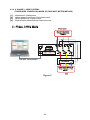
1
GOPAL
OPERATION MANUAL
3-PHASE PRECISION POWER METER
PA-600
Gopal Electronics
TABLE OF CONTENTS
PREFACE------------------------------------------------------------------------------------------------------ 1
Purpose of this Manual----------------------------------------------------------------------------- 1
Who should use this Manual?---------------------------------------------------------------------1
Safety Precautions----------------------------------------------------------------------------------- 1
Manual Organization-------------------------------------------------------------------------------- 1
1. INTRODUCTION------------------------------------------------------------------------------------------ 2
1.1 Unpacking Your GPPM-------------------------------------------------------------------------2
1.2 Use of all Items Provided With GPPM----------------------------------------------------- 2
1.3 Features------------------------------------------------------------------------------------------- 2
1.4 Applications--------------------------------------------------------------------------------------- 2
1.5 Description---------------------------------------------------------------------------------------- 3
1.6 System Configuration-------------------------------------------------------------------------- 3
1.7 Specifications of Model PA-600 ------------------------------------------------------------- 4
1.8 Front Panel--------------------------------------------------------------------------------------- 6
1.9 Rear Panel---------------------------------------------------------------------------------------- 7
2. FUNCTIONAL DESCRIPTION------------------------------------------------------------------------ 8
2.1 Display Guide------------------------------------------------------------------------------------ 8
2.2 Function of Push Button Switches---------------------------------------------------------- 8
2.3 Working with GPPM---------------------------------------------------------------------------- 9
2.4 Parameters on LCD ----------------------------------------------------------------------------9
2.5 Brief Explanation of some Important Push Buttons------------------------------------ 11
2.5.1 HLDA-------------------------------------------------------------------------------------- 11
2.5.2 HLD --------------------------------------------------------------------------------------- 11
2.5.2.1 Save in Storage Memory--------------------------------------------------- 11
2.5.2.2 Read from Storage Memory----------------------------------------------- 11
2.5.2.3 Incremental Save In Storage Memory---------------------------------- 11
2.5.2.4 Erase all Memory in 2 Minutes? ----------------------------------------- 12
2.5.3 FORWARD and BACKWARD-------------------------------------------------------12
2.5.4 MODE------------------------------------------------------------------------------------- 12
2.5.4.1 How to Enter the mode function----------------------------------------- 12
2.5.4.2 How to Exit the mode function------------------------------------------- 12
2.6 Different Types Of Menu In Mode Function--------------------------------------------- 13
2.6.1 Set Mode------------------------------------------------------------------------------- 13
2.6.2 Set Average Sample----------------------------------------------------------------- 13
2.6.3 Set 7Seg Parameter----------------------------------------------------------------- 13
2.6.4 Set 7Seg Intensity-------------------------------------------------------------------- 14
2.6.5 Set LCD Default Page---------------------------------------------------------------14
2.6.6 Set RPM Divisor---------------------------------------------------------------------- 14
2.6.7 Set Pole--------------------------------------------------------------------------------- 15
2.6.8 Enable RPM/SLIP Mode------------------------------------------------------------ 15
2.6.9 Default Setting-------------------------------------------------------------------------15
2.6.10 Set CT Ratio(for model PA-140 only)--------------------------------------------16
2.6.11 Set PT Ratio(for model PA-140 only)-------------------------------------------- 16
3. PROTECTING YOUR GPPM------------------------------------------------------------------------- 17
3.1 Transient Overload----------------------------------------------------------------------------- 17
3.2 Current Overload------------------------------------------------------------------------------- 17
3.3 Surge Protection-------------------------------------------------------------------------------- 17
3.4 Circuit Breakers--------------------------------------------------------------------------------- 17
3.5 Noise Caused By Magnetic Loops--------------------------------------------------------- 17
3.6 Noise Caused By Ground Loops------------------------------------------------------------17
4. DIFFERENT MODE OF TESTING----------------------------------------------------------------4.1 Testing Instrumentation Setup-----------------------------------------------------------4.2 Wiring Mode----------------------------------------------------------------------------------4.3 Hardware Connections--------------------------------------------------------------------4.3.1 1 - Phase 2 - Wire System--------------------------------------------------------4.3.2 2 - Phase 3 - Wire System---------------------------------------------------------
18
18
18
18
18
19
5. GPPM WITH COMPUTER INTERFACE--------------------------------------------------------5.1 Shakehand With Computer---------------------------------------------------------------5.2 Connection With Computer---------------------------------------------------------------5.3 Communication Parameters--------------------------------------------------------------5.4 Minimum System Requirement ---------------------------------------------------------5.5 Gopal Data Transfer Tool------------------------------------------------------------------5.6 Installation of Software --------------------------------------------------------------------5.7 How does Gopal Data Transfer Tool Works-------------------------------------------
20
20
20
20
20
20
20
20
6. FREQUENTLY ASKED QUESTIONS------------------------------------------------------------Figure 1 System Configuration --------------------------------------------------------------Figure 2 Front Panel of GPPM --------------------------------------------------------------Figure 3 Rear Panel of GPPM --------------------------------------------------------------Figure 4 Connection Diagram for Single Phase Two Wire System-----------------Figure 5 Connection Diagram for Two Phase Three Wire System------------------
21
3
6
7
18
19
PREFACE
PURPOSE OF THIS MANUAL
This manual contains most of the information required for proper installation and general use
of the GOPAL make Precision Power Meter. To achieve maximum capability and to ensure
proper use of the instrument, please read this manual deeply before operating the
Instrument. Keep this manual in a safe place for quick reference whenever a question should
arise.
WHO SHOULD USE THIS MANUAL?
This manual is intended for those operators who are planning to use GOPAL make Precision
Power Meter for power measurement purpose either as a stand-alone instrument or in
conjunction with Gopal Data Transfer Tool.
SAFETY PRECAUTIONS
ê
[1.] Make sure that there must be presence of proper ground in your power supply system.
[2.] Make sure that GOPAL Precision Power Meter is earth-grounded, to ensure your
personal safety and proper operation.
[3.] Check line voltage (it must be within the limit of 210V to 250V) before operating the
instrument.
[4.] Make sure that any machine under test is equipped with appropriate safety guards.
[5.] Don't turn the Instrument on and off instantly. It is a micro-controller-based instrument
and it may affect to the performance of the Instrument.
[6.] Warmup the Instrument for at least 30 minutes to get proper measurement & specified
accuracy.
[7.] Make proper wiring before use. Wiring diagrams are given on the top of Instrument.
NOTE:[1.] While every precaution has been exercised in compilation of this document to ensure
the accuracy of its contents, Gopal Electronics assumes no responsibility for errors or
omissions. Additionally, no liability is assumed for any damages that may be the result of the
use of the information contained within this Publication.
[2.] Word 'GPPM' is used for “Gopal Precision Power Meter” throughout this manual.
MANUAL ORGANIZATION
This section gives a brief overview of the structure of the manual and the information it
contains.
The structure of the manual is as follows:
Chapter 1:Introduction - Brief Introduction about GPPM, it's accessories and technical
data sheet which describes it's electrical characteristics.
Chapter 2:Functional Description - Description of all parts of GPPM and their functional
Use.
Chapter 3:Protecting Your GPPM - How to protect GPPM from damage.
Chapter 4:Different Mode of Testing - Different wiring connection - mode of testing.
Chapter 5:GPPM with computer- How to establish communication between GPPM &
Computer, and how to read and save data in Memory card.
Chapter 6:Frequently Asked Questions- Frequently asked questions about GPPM and
it's use.
1
1. INTRODUCTION
1.1
UNPACKING YOUR GPPM
Make sure that the carton contains following items:
[1.] Precision Power Meter Main unit
=1
[5.]
[2.] AC Mains cord
=1
[6.]
[3.] RS-232 Serial interface wire.
=1
[7.]
[4.] Current terminal nuts pre-fitted
=6
1.2
User's Manual
Test Report
Software CD
=1
=1
=1
USE OF ALL ITEMS PROVIDED WITH GPPM
[1.] GPPM is used for measurement and testing of AC machines.
[2.] Main's cord is given to plug in GPPM to Auxiliary power supply.
[3.] RS-232 Cable is given to connect GPPM with computer for communication.
[4.] Nut set of 80A is provided to make permanent connection of 3-phase power supply to
current input terminal of GPPM and power supply connection of a load.
[5.] User's Manual is necessary as a guide for proper operation of GPPM.
[6.] Test Report is provided for reference.
[7.] A Software CD is provided with free demo software (Data Transfer Tool) in order to
communicate GPPM with Computer.
1.3
FEATURES
Single/Three Phase Capabilities For single & three phase power measurements.
Interface
RS -232 serial interface.
Data Transfer Rate
115200 bps.
Liquid Crystal Display
High-quality, easy to read four lines with 20 alphanumeric
character display. It displays all measured parameters of GPPM.
Seven Segment Display
Seven digits high glow type Red display for long distance view
which shows any one parameters at a time.
Four Extra Inputs(10V DC)
To measure any parameter which is of 10V DC like Flow,
Pressure, Temperature, DC Volt etc.
RPM/SLIP RPM Input(5Volt)
To measure RPM of Motor or Slip RPM of Submersible
2 pump.
Inbuilt Memory (M-125)
It has memory which can store upto 125 test results (of all
parameters).
Measurement
Continuous
Input power of the Instrument
AC 230V / 50Hz (110V /60Hz on request)
Isolation
1000 Vrms input to Earth
Special Features
1.Upto potential difference of 1000V , between input terminal to
ground, you can directly measure current upto specified range.
2. It can be used as a Table top or Rack mounting.
1.4 APPLICATIONS
[1.] Testing of single phase & three phase AC transformer and motor.
[2.] Testing & calibration of Instruments like Energy meter, Volt meter, Ammeter, Wattmeter, PF-meter etc.
[3.] Testing of Household appliances such as Heaters, Microwave Ovens, TV, Blenders,
Mixers, Lamps, Ballasts, Fans, Air Conditioners, Refrigerators etc.
2
1.5
DESCRIPTION
[1.] GPPM is a user - friendly instrument and ideal for numerous power measurement
applications.
[2.] The instrument is equipped with latest technology for bidirectional measurement, so
you can measure parameter in both directions. Bidirectional means it can take
measurement of watt in both cases: like change of wiring direction or change in
power factor i.e. lead to lag or lag to lead.
[3.] It measures and displays True RMS Volt, True RMS Current, Active Power, Reactive
Power, Apparent Power, Power Factor, Frequency of V1, Mean/ Rectified/ Peak Value/
Crest Factor/ Form Factor of Voltage and Current Input.
[4.] You can measure 10 volt DC through it’s four Extra input viz. M1, M2, M3, M4, RPM/Slip
RPM through Extra Input Terminals which are provided at the rear panel.
[5.] It has separate ADC to measure all basic parameters of each phase simultaneously.
[6.] You can also see all basic parameters simultaneously on your computer by using RS232 serial interface wire and software called”Data Transfer Tool".
[7.] It is a portable instrument so you can easily handle it.
1.6
SYSTEM CONFIGURATION
One basic configuration is given below. Working of complete system can be understood by
following Diagram.
4 wire Connection
3Phase source
Max applicable Voltage
N:Phase < 600V AC or
800V Peak
N
R
Y
B
RS-232 Connection
Circuit breaker
Max applicable Current
per Phase < 80A AC or
110A Peak
Load
Figure 1
3
1.7 SPECIFICATIONS OF MODEL PA-600 [AT 25°C ± 5°C AFTER 30 MIN. WARM-UP]
GENERAL SPECIFICATIONS
Warm up time
Operating temperature
Operating humidity
30 minutes
20°C to 45°C
20% to 75% RH (non condensation)
Storage temperature
25°C to 50°C
Insulation resistance
40MÙ or higher at 600V all of the following area
Voltage input terminal to case
Current input terminal to case
Voltage input terminal to Current input terminal Case to power supply
Insulation withstand voltage
Power supply
Power consumption
Size
Panel mounting cut out size
Weight
2000V for 1 min. At 50 Hz across all of the following area
Voltage input terminal to case
Current input terminal to case
Voltage input terminal to Current input terminal
210V - 250V / 50Hz
15VA maximum
280 X 260 X 130 mm (l x b x h) including projection
280 x 115 mm
3.5kg approximate.
INPUT SPECIFICATIONS
Parameter
Voltage
Current
Input type
Resistance voltage divider
Current to voltage converter
Rated Values
600Vrms for PA-600 &
140Vrms for PA-140
80Arms for PA-600, 8Arms for
PA-600 - 8A & 5A for PA-140
Measuring instrument
loss (Input resistance)
Approx. 2M Ù
Approx. 1m Ù
Maximum Instantaneous
allowed input
(1cycle,30ms duration)
Peak value - 1.5 kV for PA-600 &
350 V for PA-140
RMS value - 1.1 kV for PA-600 &
250 V for PA-140
(Whichever is less)
Peak value:- 200A for PA-600,20A for
PA-600-8A & 12A for PA-140
RMS value:- 150A for PA-600,15A for
PA-600-8A & 9A for PA-140
(Whichever is less)
Maximum instantaneous
allowed input
(1second duration)
Peak value:-1.4 kV for PA-600 &
195V for PA-140
RMS value:-1.0 kV for PA-600 &
230V for PA-140
(Whichever is less)
Peak value:- 150A for PA-600,15A for
PA-600-8A & 9A for PA-140
RMS value:- 100A for PA-600,10A for
PA-600-8A & 6A for PA-140
(Whichever is less)
Maximum continuous
allowed input
Peak value:- 850V for PA-600 &
200V for PA-140
RMS value:- 600V for PA-600 &
140V for PA-140
(Whichever is less)
Peak value:- 120A for PA-600,12A for
PA-600-8A & 7A for PA-140
RMS value:- 80A for PA-600,8A for
PA-600-8A & 5A for PA-140
(Whichever is less)
Input terminal type
Banana socket
(wire fit type)
4
Direct input: large binding Post (with
1/4” BSW copper stud with
insulated nut)
EXTRA INPUT SPECIFICATIONS - M1,M2,M3,M4,RPM
L type terminal at rear side
Accuracy / Remark
Input
Input type
± 0.25 % FSD
Withstand up to 20V peak
DC
Maximum Input
10V
RPM CARD Input
Compatible with Gopal make rpm & slip card for measurement of motor & pump rpm
Note
External inputs are useful for any converter connectivity and useful
To measure Temperature, Torque, Flow, Pressure etc.
CALCULATION FUNCTIONS
Parameter
3 Wire
Volt V
V=(V1+V2)/2
V1= 3 V1
V2= 3 V2, V3= 3 V3
V=(V1+V2+V3)/3
Current I
I = (I1 + I2)/2
I = (I1 + I2 + I3)/3
Active Power P
P = P1 + P2
V*1.73205 mode
Power Factor PF
PF=(PF1+PF2)/2
Apparent Power S
S1 = V1 x I1
S2 = V2 x I2
S = S1+ S2
Reactive Power Q
Mean Volt
4 Wire
V = (V1+V2+ V3)/3
P = P1+ P2 + P3
PF =(PF1 + PF2 + PF3)/3
S1 = V1 x I1
S2 = V2 x I2
S3 = V3 x I3
S = S1+S2+S3
Q = S² - P²
V mean = 1.11072 x Voltage rectified
Crest Factor cf
cf = Peak Value/RMS Value
Form Factor ff
ff = RMS Value/Average Value
Notes:- 1. If the input contains distorted wave, the calculation based parameters may not match to those
of other measuring instruments based on different measuring principles.
2. If either voltage or current falls to 10% of the range rating or less, then the apparent Power (S),
power factor (PF) and reactive power (Q) may be displayed with errors.
3. No sign of power factor is displayed when current lags the voltage and negative Sign is displayed
when current leads the voltage.
MEASUREMENT FUNCTIONS
Parameter
Voltage / Current / Active power
System
Digital sampling, Sum of average method
Conditions: Accuracy
(within one year after calibration)
Temperature: 25°± 5° C
Humidity: 30 - 75% RH
Input waveform: Sine wave power
factor: 1.0
Display digits: 5 / 6 digits
AVG: 8 sample mode
Additional power factor effect on
active power measurement
Effective input range
Display updating value
Frequency Measurements
Frequency range
Accuracy
30 Hz to 44 Hz
45 Hz to 65 Hz
66 Hz to 800 Hz
±(0.2% of rdg + 0.2% of rng)
±(0.1% of rdg + 0.1% of rng)
±(0.2% of rdg + 0.2% of rng)
Peak/Mean above x2
At 50Hz 0.035° or time delay errors 2.5 µS
10-100% of Voltage, 1-100% current range rating
1/ 2/ 3/ 4/ 5/ 6/ 7/ 8 seconds selectable by sample Average menu
Conditions: Input > 30% of V1 from 30 to 800Hz
Accuracy ± 0.1%
Frequency measured at input of V1 to Neutral
Note:- Specifications are subject to change without prior notice for further improvement of products.
5
1.8
FRONT PANEL
A
B
C D E F
G
H
I
J
S
R QP O N M L K
Figure 2
A
7 digit Seven Segment High Glow Display
B
20 x 4 LCD Display
C
Push Button EX-M to measure M1,M2,M3,M4,RPM/SLIP,F etc.
D
Push Button MODE to Enter mode function.
E
Push Button HLDA for Measure all and Hold.
F
Push Button HLD for Instant Hold.
G
Push Button Backward.
H
Push Button Increment.
I
Push Button Forward.
J
Push Button Decrement.
K
Push Button IMP to measure I,Irect,Imean,Ipeak,Icf and Iff
L
Push
Push Button
Button Increment.
I1MP to display I1,Irect1,Imean1,Ipeak1,Icf1 and Iff1
M
Push Button VMP to display V, Vrect,Vmean,Vpeak,Vcf and Vff & F
N
Push Button V1MP to display V1,Vrect1,Vmean1,Vpeak1,Vcf1,Vff1& F
O
Push Button S-Q to display S1, S2, S3, S, Q1, Q2, Q3 and Q.
P
Push Button P-PF to display P1, P2, P3, P, Pf1, Pf2, Pf3 and Pf.
Q
Push Button V-I to display V1, V2, V3, V, I1, I2, I3 and I.
R
Push Button to display default page.
S
Instrument Power On/Off switch
6
1.9
REAR PANEL
A
B BB B
W
V U T SRQP O
C
D E
N
M L
H
F G
K
J
I
Figure 3
A
AC 230V/50Hz mains power supply socket
B
Common Ground input of 10 V DC meter M1,M2,M3,M4
C
Banana terminal to input Neutral of Phase 1
D
Banana terminal to Volt input of Phase 1
E
Banana terminal to input Neutral of Phase 2
F
Banana terminal to Volt input of Phase 2
G
Banana terminal to input Neutral of Phase 3
H
Banana terminal to Volt input of Phase 3
I
Binding post stud of Ammeter to be connect to Load of Phase 3
J
Binding post stud of Ammeter to be connect to Phase 3
K
Binding post stud of Ammeter to be connect to Load of Phase 2
L
Binding post stud of Ammeter to be connect to Phase 2
M
Binding post stud of Ammeter to be connect to Load of Phase 1
N
Binding post stud of Ammeter to be connect to Phase 1
O
Input of external meter M4 applicable maximum voltage = 10V DC
P
Input of external meter M3 applicable maximum voltage = 10V DC
Q
Input of external meter M2 applicable maximum voltage = 10V DC
R
Input of external meter M1 applicable maximum voltage = 10V DC
S
Clock/Pulse Input of external Gopal Make RPM Card
T
-5 V DC output to external Gopal Make RPM Card
U
Common Ground input/output of external Gopal Make RPM Card
V
+5 V DC output to external Gopal Make RPM Card
W
9 Pin D socket for RS-232 serial interface
7
2. FUNCTIONAL DESCRIPTION
2.1 DISPLAY GUIDE
ABBREVIATION
MEANING
ABBREVIATION
Rect
True RMS AC Volt
V1,V2,V3
I1,I2,I3
True RMS AC Current
cf
P1,P2,P3
Watt (Active Power)
ff
M1
Power Factor
PF1,PF2,PF3
Apparent Power
S1,S2,S3
M2
Q1,Q2,Q3
Reactive Power
M3
M4
Frequency of V1
F
Average Volt
RPM
V
RPM÷
Average Current
I
P
Total Watt
%S
Average Power Factor
Pole
PF
Total Apparent Power
Int
S
Total Reactive Power
Q
----Low
OL
LO
MEANING
Rectified
Crest Factor
Form Factor
Extra meter 1
Extra meter 2
Extra meter 3
Extra meter 4
Revolution per minute
RPM Divisor
Percentage Slip
Pole of motor
Intensity of 7seg. Display
No measurement
Over Load
2.1 FUNCTION OF PUSH BUTTON SWITCHES
Sr. No. Button Name Primary Function of Button
To Display Extra Parameter Page.
1
EX-M
MODE
2
To Enter Mode Function.
3
To measure all parameters and hold after storing in RAM.
HLDA
4
HLD
To hold the measurement.
5
PAGE
To display Default set page.
Sr. No.
6
To display V1, V2, V3, V and I1, I2, I3,
V- I
7
To display Active P1, P2, P3, P, and Pf1, Pf2, Pf3
P-PF
S-Q
To display S1, S2, S3, S and Q1, Q2, Q3, Q
8
9
To display V1, Vmean1, Vrect1, Vpeak1, Vcf1, Vff1, F.
V1MP
To display V, Vmean, Vrect, Vpeak, Vcf, Vff, F.
VMP
10
11
I1MP
To display I1, Imean1, Irect1, Ipeak1, Icf1, Iff1.
6 Iff.
IMP
12
To display I, Imean, Irect, Ipeak, Icf,
To
display
incremented
parameter
in
7seg LED.
13
To display decremented parameter in 7seg LED.
14
15
To Increment Page to be displayed.
To Decrement Page to be displayed.
16
Sr. No. Button Name Secondary Function of Button
To Exit from mode or other setting function.
ESC
1
ENTR
2
To save setting which you have set.
AVG
To set Sample Average menu.
3
To set parameter to be displayed in 7seg display.
4
7SGP
To set Intensity of 7Segment LED Display.
7SGI
5
6
To set default page to be displayed in LCD.
LCDF
7
RPMS
To set Divisor of RPM.
8
To set Motor Pole which is used to calculate SLIP RPM.
POLE
To enable/disable RPM/ SLIP mode.
SLIP
9
DSET
To do Default setting of mode menu.
10
To shift cursor forward for setting of any parameter of related menu.
11
12
To shift cursor backward for setting of any parameter of related menu.
8
2.3 WORKING WITH GPPM
When you switch ON the Instrument, set-up process takes
apprx.1 min. After that it shows message on LCD as shown
in adjacent figure. After few seconds, display will become
blank. Now measurement gets start, related to parameters
of LCD Default Page and LCD shows parameter of that
page, where as 7seg LED display shows parameter which
has been set for it.
GOPAL POWER METER
MODEL:- PA - 600
SR.NO :- PAXXXXX
HELP :- 079-22820927
2.4 PARAMETERS ON LCD
[1.] You can see almost all useful parameters like V, I, P, PF, S, Q, F in Page 1,2,3 and12.
Extra parameters like M1, M2, M3, M4, RPM/Slip RPM, F in Page 13 and other
parameters like Mean, Rect, Peak, cf, ff, F of Volt and current in Page 4,5,6,7,8, 9,10,11.
At last you can see status of some setting in Page 14 called Status Page.
[2.] As the measurement starts you can see a page which has been set in menu of Set LCD
as Default Page. By default Page 12 has been set in factory default setting.
[3.] You can see all pages one by one by pressing Up and Down arrow Button.
[4.] You can see any parameter one by one in 7seg LED by pressing Forward and
Backward Button.
Page- 1:Line 1:- V1 & I1, RMS Volt and Current of phase1.
Line 2:- V2 & I2, RMS Volt and Current of phase2.
Line 3:- V3 & I3, RMS Volt and Current of phase3.
Line 4:- V & I,Average of RMS Volt and Current of all phases.
V1
V2
V3
V
Page- 2:Line 1:- P1 & PF1, Active Power and Power factor of phase1.
Line 2:- P2 & PF2, Active Power and Power factor of phase2.
Line 3:- P3 & PF3, Active Power and Power factor of phase3.
Line 4:- P & PF, Total Active Power & Average PF of all phases.
P1 48000
P2 48000
P3 48000
P 144000
Page- 3:Line 1:- S1 & Q1, Apparent and Reactive power of phase1.
Line 2:- S2 & Q2, Apparent and Reactive power of phase2.
Line 3:- S3 & Q3, Apparent and Reactive power of phase3.
Line 4:- S & Q, Total Apparent &Reactive power of all phases.
600.00
600.00
600.00
600.00
S1 48000
S2 48000
S3 48000
S 144000
I1 80.000
I2 80.000
I3 80.000
I 80.000
PF1 1.0000
PF2 1.0000
PF3 1.0000
PF 1.0000
Q1 48000
Q2 48000
Q3 48000
Q 144000
Page- 4:Line 1:- V1 & cf, RMS Volt and Volt Crest Factor of phase1.
Line 2:- mean & ff, Mean Volt and Volt Form Factor of phase1.
Line 3:- rect & F, Rectified Volt and Freq of V1.
Line 4:- Peak Volt of phase1.
V1
mean
rect
peak
600.00
600.00
600.00
850.00
cf 1.414
ff 1.110
F 50.00
Page- 5:Line 1:- V2 & cf, RMS Volt and Volt Crest Factor of phase2.
Line 2:- mean & ff, Mean Volt and Volt Form Factor of phase2.
Line 3:- rect - Rectified Volt of phase2.
Line 4:- Peak Volt of phase2.
V2
mean
rect
peak
600.00
600.00
600.00
850.00
cf 1.414
ff 1.110
Page- 6:Line 1:- V3 & cf, RMS Volt and Crest Factor of phase-3.
Line 2:- mean & ff, Mean Volt and Form Factor of phase-3.
Line 3:- rect - Rectified Volt of phase-3.
Line 4:- Peak Volt of phase -3.
V3
mean
rect
peak
600.00
600.00
600.00
850.00
cf 1.414
ff 1.110
9
Page- 7:Line 1:- V & cf, RMS Volt and Volt Crest Factor Average.
Line 2:- mean & ff, Mean Volt and Volt Form Factor Average.
Line 3:- rect & F, Rectified Volt Average & Freq of V1.
Line 4:- Peak Volt Average.
V
mean
rect
peak
600.00
600.00
600.00
850.00
cf 1.414
ff 1.110
F 50.00
Page- 8:Line 1:-I1 & cf, RMS Current & Current Crest Factor of phase1.
Line 2:-mean & ff, Mean Current & Current Form Factor of phase1.
Line 3:-rect - Rectified Current of phase1.
Line 4:-Peak Current of phase1.
I1
mean
rect
Peak
80.000
80.000
80.000
115.00
cf 1.414
ff 1.110
Page- 9:Line 1:-I2 & cf, RMS Current & Current Crest Factor of phase2.
Line 2:-mean & ff, Mean Current & Current Form Factor of phase2.
Line 3:-rect - Rectified Current of phase2.
Line 4:-Peak Current of phase2.
I2
mean
rect
peak
80.000
80.000
80.000
115.00
cf 1.414
ff 1.110
Page- 10:Line 1:-I3 & cf, RMS Current & Current Crest Factor of phase3.
Line 2:-mean & ff, Mean Current & Current Form Factor of phase3.
Line 3:-rect - Rectified Current of phase3.
Line 4:-Peak Current of phase3.
I3
mean
rect
peak
80.000
80.000
80.000
115.00
cf 1.414
ff 1.110
Page- 11:Line 1:-I & cf, RMS Current and Current Crest Factor Average.
Line 2:-mean & ff, Mean Current &Current Form Factor Average.
Line 3:-rect - Rectified Current Average.
Line 4:-Peak Current Average.
I
mean
rect
peak
80.000
80.000
80.000
115 .00
cf 1.414
ff 1.110
Page- 12:Line 1:- V & I, RMS Volt and Current Average.
Line 2:- P & PF, Total Active Power & Power Factor Average.
Line 3:- S & Q, Total Apparent and Reactive Power.
Line 4:- F & M1, Frequency of V1 and Extra meter M1.
V 600.00
P 144000
S 144000
F 50.00
Page- 13A:- (when RPM Mode is enabled)
Line 1:- M1 & RPM, Extra Meter1 and RPM meter.
Line 2:- M2 & RPM÷,Extra Meter2 and RPM Divisor.
Line 3:- M3 & F,Extra Meter3 and Frequency of V1.
Line 4:- M4, Extra meter M4.
M1 10.00
M2 10.00
M3 10.00
M4 10.00
RPM 00000
RPM÷ 0001
F
50.00
Page- 13B:- (when SLIP Mode is enabled)
Line 1:- M1 & RPM, Extra Meter1 and SLIP RPM meter.
Line 2:- M2 & %S, Extra Meter2 and %Slip.
Line 3:- M3 & F, Extra Meter3 and Frequency of V1.
Line 4:- M4 & Pole, Extra meter M4 and Slip Pole.
M1 10.00
M2 10.00
M3 10.00
M4 10.00
RPM 3000
%S 00.00
F
50.00
Pole
2
I 80.000
PF 1.0000
Q 144000
M1 10.00
Page- 14:- : STATUS PAGE : Line 1:- Status Page
LED V
SAMPLE 8
Line 2:- Name of 7seg parameter, & sample average.
INT
HIGH
Line 3:- Status of Intensity of 7 Seg.
MODE 4 WIRE
ON
Line 4:- Wiring Connection mode & Status of meas. On/HLDA/HLD
10
2.5
BRIEF EXPLANATION OF SOME IMPORTANT PUSH BUTTONS
2.5.1 HLDA:- It is used to hold a processor after taking measurement of all parameters. By
use of this button you can hold measurement, save and read all parameters inside storage
memory. Press this button again to release hold.
2.5.2 HLD:- It is used to hold a processor for instant. By use of this button you can hold the
measurement, save and read all parameters in storage memory. Press this button again to
release hold.
2.5.2.1 SAVE IN STORAGE MEMORY
Q.
Ans.
[1.]
[2.]
[3.]
[4.]
[5.]
[6.]
[7.]
How can you save parameters Inside Storage Memory in Hold condition?
Press HLD or HLDA button, so measurement will get hold after few seconds.
Now you can see a message “hld” on 7segment LED Display.
Press MODE Button, so you can see “Save Data” & “Select Address XXX” on LCD
Set appropriate address No. (From 1 to 125) at whichever memory address you want
to save all parameters by using four arrow buttons and then press ENTR to save them.
After saving in memory it shows a message on LCD “Data has been saved “.
After some moments you can see another message “Read Data” and “Select
Address XXX”.
If you want to read any data then proceed further other wise press ESC button to exit.
2.5.2.2 READ FROM STORAGE MEMORY
Q.
Ans.
[1.]
[2.]
[3.]
[4.]
[5.]
[6.]
[7.]
How can you read parameters from Storage Memory in Hold condition?
Press HLD or HLDA button so measurement will get hold after few seconds.
Now you can see a message “hld” on 7segment LED Display.
Press MODE button two times so you can see“Read Data”&“Select Address XXX”
on LCD
Now set appropriate address No. ( From 1 to 125) from whichever memory address
you want to read all the parameters by using four arrow buttons and then press ENTR
to read them.
After reading, it displays a message on LCD “Data has been read”. At the same time
data will be transferred to PC if the software "Data transfer tool" is opened and RS-232
wire is connected to PC.
After few minutes, you can see another message “Incremental Save” and “Select
Address XXX”.
If you want to set Incremental save then proceed further other wise press ESC to exit.
2.5.2.3 INCREMENTAL SAVE IN STORAGE MEMORY
Q.
What does it mean by Incremental Save Mode, it’s use and how can you set
incremental save mode and enable or disable it?
Ans. It is a mode in which you can set starting address of storing data in storage memory. You
can enable or disable Incremental save mode after setting address.
Usefulness of Incremental Save Enable:If you wish to take measurement of so many AC machines on this GPPM and want to store all
measuring data in storage memory automatically then What to do for that? Enable
Incremental save and give starting address from which you want to start storing. After setting
it once, whenever you hold measurement, your data will be stored at particular address one
by one. You don’t have to do the process of saving them individually. After storing into the
memory a counter will automatically be incremented by one so, every time data will be stored
in next address. When whole memory is filled up by data, a message “Memory Full” will be
displayed on LCD. So this mode is useful for bulk testing.
11
Procedure to select address in Incremental save mode and Enable / Disable
Incremental Save Mode:[1.] Press HLD or HLDA button so measurement will get hold after few seconds.
[2.] Now you can see message “hld” on 7segment LED Display.
[3.] Press Mode button three times so you see “Incremental Save” & “Select Address
xxx” on LCD .
[4.] Now set appropriate address no. (From 1 to 125) from whichever memory address you
want to save the parameters by using four arrow buttons and then press ENTR.
[5.] After setting it, press MODE so, you can see a message on LCD “Incremental save
Enable?” or “Incremental save Disable?”. If you see “Incremental save Enable?”
then press ENTR so Incremental save will be enabled. If you see “Incremental save
Disable?” Then don’t press ENTR otherwise it will disable Incremental save function.
[6.] If you want to do any other function then proceed further other wise press ESC to exit.
2.5.2.4 Erase all Memory in 2 Minutes?
Q.
What does it mean by “Erase all memory” and procedure to perform this
function?
Ans. It is a function by which you can erase complete storage memory. If you want to erase
whole memory then by this function you can do it.
Procedure to perform this function:[1.] Press HLD button so measurement will get hold after few seconds.
[2.] Now you can see message “hld” on 7segment LED Display.
[3.] Press Mode button five times so you can see “Erase all Memory in 2 Minutes?”on LCD.
[4.] Now press ENTR to erase all memory. After pressing ENTR all storage memory will be
erased in approximately two minutes.
2.5.3 FORWARD AND BACKWARD:- In measurement mode, these buttons are used to
increase or decrease No. of displaying 7segment parameter from 1st parameter to last
parameter. Forward is to increase and Backward is to decrease parameter no.In mode
function these buttons are used to shift cursor left and right in LCD.
2.5.4 MODE:- This is used to get entry in the mode function. In mode function we can do
some important settings in the instrument as per our requirement. In Hold condition, you can
go to Save Data & Read Data mode by pressing MODE push button.
2.5.4.1 HOW TO ENTER THE MODE FUNCTION?
Ans.
[1.] Press mode button to enter mode function.
[2.] Now you can see first menu " Set Mode” on LCD screen .
[3.] You can go to another function menu by pressing mode button again and again.
[4.] All scroll menus in mode function are described here under: 1. Set Mode
2. Set Average Sample
3. Set 7Seg Parameter
4. Set 7Seg Intensity
5. Set LCD Default Page
6. Set RPM ÷
7. Set Pole
8. Enable RPM/SLIP Mode
9. Default Setting
10. Set CT Ratio (Only for model - PA-140)
11. Set PT Ratio (Only for model - PA-140)
2.5.4.2 HOW TO EXIT THE MODE FUNCTION?
Ans. If you wish to exit from any where in the mode function, then simply press ESC Button
12
which leads you to measurement mode and you will see parameters related to LCD Default
page on LCD screen.
2.6
DIFFERENT TYPES OF MENU IN MODE FUNCTION
2.6.1 Set Mode
Q.
What does it mean by Set Mode and how can it be useful to the user?
Ans. GPPM is designed in such a way that users can do testing by three different methods
as per their wish. This is the function which is useful to set wiring connection for different test
method in the Instrument. At the same time connection must be made as per selected wiring
mode. You can take reference from connection diagrams to do connection. Three types of
wiring modes are given below. Users can set any of the following wiring mode as per their
requirement of testing.
[1.] 4 Wire Mode (for phase to neutral measurement)
[2.] 3 Wire Mode (for two watt meter type measurement)
[3.] V* 1.73205 Mode (for phase to neutral measurement and voltage channel will be
multiplied by 3).
Q.
Ans.
[1.]
[2.]
[3.]
[4.]
[5.]
[6.]
[7.]
How can you Set Wire Connection Mode?
First press MODE button to enter the MODE function.
Now, you can see this menu on LCD.
Select any of three connection mode by using UP & DOWN arrow buttons.
Press ENTR to save your selected connection mode.
Press ESC to exit from mode function or you can proceed further for another setting.
In this way you can set connection mode.
Once this mode is set then this setting will be stored in the Instrument.
2.6.2 Set Average Sample
Q.
What does it mean by Set Average Sample and how can it be useful to the user?
Ans. GPPM is designed in a way that user can set sample average from 1 to 8 sample. If the
user sets 8 sample average then it will give best result. Accuracy is specified on 8 sample
average. Processor takes sample of all parameters as per selection of sample then displays
them after calculating average.
Q.
Ans.
[1.]
[2.]
[3.]
[4.]
[5.]
[6.]
[7.]
How can you Set Average Sample ?
First press MODE button to enter the MODE function.
Now, you can see this menu by pressing MODE or AVG switch one time.
Select any no. of the sample average by using UP & DOWN arrow buttons.
Press ENTR to save selected sample average.
Press ESC to exit from mode function or you can proceed further for another setting.
In this way you can set sample average.
Once you set no. of average sample then this setting will be stored in the Instrument.
2.6.3 Set 7Seg Parameter
Q.
What does it mean by Set 7Seg Parameter and how can it be useful to the user?
Ans. By this mode user can set parameter no. which will be displayed by 7segment LED
Display which has been given as big long distance view display. You can see any one of all
the parameters in this display which has been measured by the Instrument.
Q.
How can you Set 7seg Parameter?
Ans.
[1.]
First press MODE button to enter MODE function.
13
[2.]
[3.]
[4.]
[5.]
[6.]
[7.]
Now you can see this menu by pressing MODE switch two times or 7SGP Switch
once.
Select any one of all 7seg parameter by use of four arrow buttons.
Press ENTR to save selected 7seg Parameter.
Press ESC to exit from mode function or you can proceed further for another setting.
In this way you can set 7segment parameter.
Once this mode is set then this setting will be stored in the Instrument.
Note:- If you want to set any 7segment parameter in measurement mode means when
measurement is going on then you can set it by pressing FORWARD & BACKWARD arrow
button on temporary basis. It will not be saved in ROM, it is a temporary setting. Every time
when you switch on the Instrument you will see only the parameter which has been set by you
in mode function.
2.6.4 Set 7 Seg Intensity
Q.
What does it mean by Set 7Seg Intensity and how can it be useful to the user?
Ans. By this mode users can set Intensity of 7segment LED display as per their wish.
Q.
How can you Set 7seg Intensity?
Ans.
[1.]
[2.]
[3.]
[4.]
[5.]
[6.]
[7.]
First press MODE button to enter the MODE function.
You can see this menu by pressing MODE button three times or 7SGI button once.
Select any of three Intensity level i.e. High, Med. or Low by using UP, DOWN arrow
Buttons.
Press ENTR to save selected 7 Segment Intensity.
Press ESC to exit from mode function or you can proceed further for another setting.
In this way you can set 7segment Intensity.
Once this setting is set then this setting will be stored in the Instrument.
2.6.5 Set LCD Default Page
Q. What does it mean by Set LCD Default Page and how can it be useful to the user?
Ans. By this mode user can set a page which is most important to see on LCD and after
selecting it he will have this page on LCD whenever Instrument Power supply gets on or by
pressing PAGE Button.
Q.
How can you Set LCD Default Page?
Ans.
[1.]
[2.]
[3.]
[4.]
[5.]
[6.]
[7.]
First press MODE button to enter the MODE function.
Now you can see this menu by pressing MODE button four times or LCDP button once.
Select any one page by using UP & DOWN arrow buttons.
Press ENTR to save selected page as a Default page for LCD.
Press ESC to exit from mode function or you can proceed further for another setting.
In this way you can set LCD Default Page.
Once this setting is set then this setting will be stored in the Instrument.
2.6.6 Set RPM ÷
Q.
What does it mean by Set RPM ÷ and how can it be useful to the user?
Ans. This function is useful for RPM measurement in motor testing. By this mode you can
Set Divisor value for RPM meter. Some times for high speed motor or some special types of
motor user make some arrangement to sense rpm by use of geared wheel or proximity
sensor etc. So he has to set rpm divisor as per gear teeth to measure rpm very accurately.
14
Q.
Ans.
[1.]
[2.]
[3.]
[4.]
[5.]
[6.]
[7.]
How can you Set RPM ÷ (divisor) ?
First press MODE button to enter MODE function.
You can see this menu by pressing MODE button five times or RPMS button once.
Set RPM ÷ by use of four arrow buttons.
Press ENTR to save setting of RPM ÷.
Press ESC to exit mode function or proceed further for another setting.
In this way you can set RPM ÷.
Once RPM divisor is set then this setting will remain in the Instrument.
2.6.7 Set Pole
Q.
What does it mean by Set Pole and how can it be useful to the user?
Ans. Set pole means setting of no. of Pole as per Pole of submersible pump. A Value of Pole
is used for testing of Slip RPM of Submersible pump. This value is essential in calculation of
Slip RPM.
Q.
Ans.
[1.]
[2.]
[3.]
[4.]
[5.]
[6.]
[7.]
How can you Set Pole?
First press MODE button to enter MODE function.
Now you can see this menu by pressing MODE button six times or POLE button once.
Set Pole value by pressing UP, DOWN arrow buttons.
Press ENTR to store setting of Pole.
Press ESC to exit mode function or you can proceed further for another setting.
In this way you can set Pole.
Once Pole is set then this setting will be stored in the Instrument.
2.6.8 Enable RPM/SLIP Mode?
Q. What does it mean by Enable RPM/SLIP Mode?
Ans. First think what do you want to enable, RPM or SLIP mode ? If you want to measure
RPM of motor then you have to enable RPM mode and if you want to measure SLIP RPM of
Submersible pump then you will have to enable Slip mode. Related parameter will be shown
in EX-M page as per setting.
Q.
How can you Enable RPM/SLIP mode?
Ans.
[1.] First press MODE button to enter MODE function.
[2.] Now you can see this menu by pressing MODE button seven times or SLIP button
once.
[3.] If RPM mode is set in the Instrument then LCD shows “Enable SLIP Mode?” and if
SLIP mode is set then LCD shows “Enable RPM Mode?”.
[4.] Press ENTR to change and store the required mode.
[5.] Press ESC to exit mode function or proceed further for another setting.
[6.] In this way you can set RPM/SLIP mode in the Instrument.
[7.] Once this mode is set then this setting will remain in the Instrument.
Note:- You must have to connect Gopal Make SLIP module between Slip coil and Slip input
terminal provided (+5V, Gnd, In, -5V) at rear panel of GPPM to measure SLIP RPM.
2.6.9 Default Setting
Q.
What does it mean by Default Setting?
Ans. Default setting means default factory setting of all mode functions. This mode will set
all functions as per factory default value which are given below.
[1.] Wire connection mode:- 4 Wire mode.
[2.] Average Sample:- 8
15
[3.]
[4.]
[5.]
[6.]
[7.]
[8.]
[9.]
[10.]
7Seg Parameter:-04:-V
7Seg Intensity:-High
LCD Default Page:-No.12 in the System
RPM Divisor:- RPM÷ :- 0001
Pole:- 2 Pole
RPM mode is enabled.
CT Ratio :- 1.00 (Only for model PA-140)
PT Ratio :- 1.00 (Only for model PA-140)
Q.
How can you do Default Setting?
Ans.
[1.]
[2.]
[3.]
[4.]
[5.]
[6.]
First press MODE button to enter MODE function.
Now you can see this menu by pressing MODE button eight times or by pressing
DSET button once.
Press ENTR to make default setting.
Press ESC to exit mode function or you can proceed further for another setting.
In this way you can do default setting.
Once this mode is set then this setting will be stored in the Instrument.
2.6.10 Set CT Ratio [for model PA-140 only]
Q.
What does it mean by Set CT Ratio and how can it be useful to the user?
Ans. This function is useful for testing of AC machines like Power Transformer at high
voltage and current, like 11 KV and 200Amp. PA-140 is having only 5A current capacity so, if
user wants to test 100 amp current then what to do? He has to use appropriate CT for that and
has to set CT ratio in GPPM according to primary and secondary turns of CT.
Q.
How can you Set CT Ratio?
Ans.
[1.]
[2.]
[3.]
[4.]
[5.]
[6.]
[7.]
First press MODE button to enter MODE function.
Now you can see this menu by pressing MODE button nine times.
Set CT Ratio by use of four arrow buttons.
Press ENTR to store CT Ratio.
Press ESC to exit from mode function or you can proceed further for another setting.
In this way you can set CT Ratio.
Once this ratio is set then this setting will be stored in the Instrument.
2.6.11 Set PT Ratio [for model PA-140 only]
Q.
What does it mean by Set PT Ratio and how can it be useful to the user?
Ans. This function is useful for testing of AC machines like Power Transformer at high voltage
and current like 11 KV and 200Amp. PA-140 is having only 140V capacity so, if user wants to
test 11KV then what to do? He has to use appropriate PT for that and have to set
appropriate PT Ratio in GPPM according to primary and secondary turns of PT.
Q.
How can you Set PT Ratio?
Ans.
[1.]
[2.]
[3.]
[4.]
[5.]
[6.]
[7.]
First press MODE button to enter MODE function.
Now, you can see this menu after pressing MODE switch ten times.
Set PT Ratio by use of four arrow buttons.
Press ENTR to save PT Ratio.
Press ESC to exit from mode function or proceed further for another setting.
In this way you can set PT Ratio.
Once this ratio is set then this setting will be storerd in the Instrument.
16
3. PROTECTING YOUR GPPM
Before GPPM is used for power measurement, guidelines to prevent transient overload,
current overload, surge protection and circuit breakers must be followed.
3.1 TRANSIENT OVERLOAD
[1.] Connect appropriate transient suppressor in parallel with all inductive loads.
[2.] Consult the suppressor vendor’s application literature for proper selection and sizing.
Caution:
[1.] Damage to GPPM can result from excessive voltage transient generated by
unsuppressed inductive load.
[2.] This damage is not within the scope of normal instrument service and is not covered in
the Gopal Electronics's warranty.
3.2 CURRENT OVERLOAD
[1.] There is no fuse in GPPM’s measuring circuits.
[2.] Excessive current passing through the load terminals will cause excessive internal
heating and as a result it may become a cause to damage the Instrument.
[3.] You must know your load condition.
[4.] Double check all connections.
[5.] If an overload occurs, immediately switch off power supply and remove all power
connections, locate that place and correct the problem before re-energizing your circuit.
[6.]
[7.]
If a circuit breaker is installed, it should be installed on the load side of GPPM. This will
keep the low impedance of the input line connected to GPPM for surge suppression.
If the line side contains a breaker, it should be delayed in operation to open, after
the load side breaker is opened.
Caution: This overload abuse is not covered by the Gopal Electronics's Warranty.
3.3
SURGE PROTECTION
Connect MOV between Phase and Neutral terminal of voltage input at rear side of
GPPM.
3.4 CIRCUIT BREAKERS
[1.] Proper use of the overload circuit breaker removes all load during an over-current
condition.
[2.] The voltage sense lines should be connected at the line side of the circuit breaker to
prevent inductive transients from entering into the GPPM as the circuit breaker opens.
[3.] Make sure that connections from the circuit breaker to the load are heavy conductors
and as short as possible. (recommended MCB = 80 Amp )
3.5 NOISE CAUSED BY MAGNETIC LOOPS
If you are taking measurements near magnetic fields, you should take necessary
precautions to avoid inducing voltages in the measurement connections. You should be
especially careful when working near conductors carrying large currents. Use twisted-pair
connections to the GPPM (if possible) to reduce the noise pickup loop area, or dress the test
leads as close together as possible. Loose or vibrating test leads will also induce error
voltage. Make sure that your test leads are tied down securely when operating near magnetic
fields. Whenever possible, use magnetic shielded material or physical separation to reduce
problem in magnetic field sources.
3.6 NOISE CAUSED BY GROUND LOOPS
When measuring voltage in circuit where the GPPM and the device-under-test are both
referenced to common earth ground, a ground loop is formed. Any voltage difference
between the two ground reference points(Vground) causes the current to flow through the
measurement leads. This cause errors, such as noise and offset voltage (usually power-line
related), which are added to the measured voltage.
17
4. DIFFERENT MODE OF TESTING
4.1 TESTING INSTRUMENTATION SETUP
Before GPPM can be utilized, it must be configured and connected to appropriate devices
which are intended for power measurement. All connections must be proper.
4.2 WIRING MODE
The GPPM has the ability to support testing up to 3-phase, so there are different ways in
which the unit can be wired up.
4.3
HARDWARE CONNECTIONS
The wiring mode selections include:
1) 1 - Phase, 2 - Wire mode (Select 4 wire connection mode)
2) 2 - Phase, 3 - Wire mode (Select 3 wire connection mode)
3) 3 - Phase, 4 - Wire mode (Select 4 wire connection mode) See Figure 1 for this
mode.
4.3.1 1- PHASE 2- WIRE SYSTEM (Select 4 wire connection mode ) :
[1.]
[2.]
[3.]
Used for Measurement of 1-phase power.
Can be wired on any input channel, most commonly used for single phase AC load
applications.
The following diagram shows connections for single phase two wire measurement.
Note:- Here V1 and Ph1 is used in connection just for explanation. You can connect single
phase Machine in any pair like V1-Ph1, V2-Ph2, V3-Ph3.
1 - Phase, 2 Wire mode
1Phase source
Max applicable
Voltage N:Phase
N
RS-232 Connection
R
Circuit breaker
Max applicable
Current per Phase
Figure 4
18
Load
4.3.2 2 -PHASE 3 - WIRE SYSTEM:(THREE WIRE CONNECTION MODE OR TWO WATT METER METHOD)
[1.]
[2.]
[3.]
[4.]
It Measures 2- phase power.
Utilizes phase 1 and phase 2 for measurement.
Utilizes phase 3 as a common wire.
All parameters related to phase 3 becomes zero.
2 - Phase, 3 Wire Mode
3Phase source
Max applicable Voltage
N:Phase < 600V AC or
800V Peak
RS-232 Connection
Circuit breaker
R
Y
B
Max applicable Current per
Phase < 80A AC or 110A
Peak
Load
Figure 5
19
5. GPPM WITH COMPUTER INTERFACE
5. 1 SHAKEHAND WITH COMPUTER
Using the GPPM with a computer enables the unit to perform at its full capacity. GPPM is
equipped with RS-232 (serial) interface.
Pin configuration of Cable connector is given as below.
End 1
End 2
RX
Pin2 : RX
Pin2 : TX
GPPM TX
Pin3 : TX
Pin3 : RX
Pin5 : GND
Pin5 : GND
5.2
[1.]
[2.]
RX
TX
PC
Ground
CONNECTION WITH COMPUTER
Connect RS-232 Interface cable from GPPM to Computer at serial communication Port.
Connect male type connector of cable to GPPM and female type connector to
Computer.
5.3 COMMUNICATION PARAMETERS
No parity bit, 8 data bit, 1 stop bit, Baud rate 115200 bps
Free of cost one Demo software viz. “Gopal Data Transfer Tool” is provided in CD with
GPPM to communicate it with Computer.
Important Note:Gopal Electronics doesn’t take any responsibility for any erratic operation by use of this
software & is not liable for any unexpected results which comes out by use of these free demo
software.
5.4
[1.]
[2.]
[3.]
[4.]
MINIMUM SYSTEM REQUIREMENT FOR THIS SOFTWARE :Operating system compatibility: Windows 95, 98, NT, 2000, ME, XP, 2003
128 MB RAM
100 MB free space on hard Disk drive
Celeron or Pentium series processor with minimum speed of 850 MHz.
5.5 GOPAL DATA TRANSFER TOOL: A tool to communicate Instrument with computer.
If you have your own test report format in Excel and wish to get test results of GPPM in that
Excel sheet then this is very useful. Here, you can send results of all testing parameters to
your selected addresses of selected sheet in selected Excel file.
5.6
[1.]
[2.]
[3.]
[4.]
[5.]
5.7
[1.]
[2.]
[3.]
[4.]
[5.]
[6.]
[7.]
[8.]
[9.]
INSTALLATION OF SOFTWARE :Insert CD of software (Gopal Data Transfer Tool ) in CD drive ,Open CD & select
setup.exe
Click at appropriate option which is given in software.
Click on Finish and restart your computer.
You will have software in folder of Data Transfer Tool in program files folder.
Shortcut “Gopal.exe” will also be created on desktop.
HOW DOES GOPAL DATA TRANSFER TOOL WORKS?
Click on Icon Gopal.exe on Desktop of Computer.
Click on Setting menu on menu bar in software if first time.
Click on Port setting & select appropriate communication port at which communication
cable is connected. Select bit rate of 115200
Click on OK Button and then click on Connect menu on menu bar.
All basic parameters comes in the software in separate phase which you can see.
Enter address of required parameters for Excel sheet.
Browse File in the Text Box of File Path and select appropriate sheet of the Excel file.
Press HOLD, then press send button so all selected parameters will go to browsed
sheet.
In this way you can use this software for your easiness to create report.
20
6. FREQUENTLY ASKED QUESTIONS
Q.1. When we apply voltage and current it shows Volts, Currents and P2 correct but show
P1 and P3 incorrectly?
Ans. Check connection of Voltage and Current. You must connect V1 - A1, V2 - A2, V3 -A3
otherwise this problem will occur.
Q.2. We have made connection of three phases to GPPM and switch on supply but three
phase variac is at its lowest position means almost 0V Position although V1, V2, V3 in GPPM
shows some Volt. Here we checked it by multi meter, there is no voltage between any two
phases but between phase and neutral it shows some volts and we haven’t connected
Neutral?
Ans. There is a possibility in your Variac that there is no connection of neutral at center
tapping so, connect neutral at its center tapping and properly earth its body.
Q.3. Connected GPPM with cable through RS-232, opened Data Transfer Tool and clicked
on connect but it didn’t get any data from GPPM?
Ans. Check RS-232 cable it may be damaged. There are two connectors one is male and
another is female connector. Check continuity of the pin.
First connector
Second connector
2nd pin
3rd pin
5th pin
3rd pin
2nd pin
5th pin
with
with
with
If continuity is ok then there may be some fault in serial port of the computer. If serial port is ok
and your problem continues then contact to Gopal Electronics.
Q. 4. From where can we purchase RS-232 cable?
Ans. It is standard RS-232 cable so you can purchase it from any local PC supplier.
Q. 5. When we switch on, GPPM is doesn’t Turn on?
Ans. Make sure that the power source you plugged in the Instrument is energized or not. If it
is not energized then energize it first. After that if it does not turn On then check continuity of
power Cable. If continuity is ok and GPPM does not turn On yet, then there may be some
problem in GPPM so contact to Gopal Electronics.
21
Gopal Electronics
Plot-11, Part-3, Amarnath Estate
Naroda Dehgam Road, Post-Naroda,
Ahmedabad - 382330
Gujarat - INDIA
--------------------------------------------Phone +91-79-22820927
Fax
+91-79-22819989
Email:- [email protected]
Web:- www.gopalepstein.com
--------------------------------------------