1
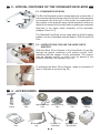
Technical
Instructions
Manual
FACE-BOW AND
ARTICULATOR
www.bioart.com.br
NOTE:
All rights reserved. No part of this publication may be reproduced, stored in a
retrieval system, or transmitted, in any form or by any electronic, mechanical,
photocopyng, recording or other means, without the prior writen consent of
Bio-Art Equipamentos Odontológicos Ltda.
Authorised Representative in the European Community:
Obelis s.a
Boulevard Général Wahis 53
1030 Brussels, BELGIUM
Tel: +(32) 2. 732.59.54
Fax: +(32) 2.732.60.03
E-Mail : [email protected]
CONTENTS
01 - Introduction . . . . . . . . . . . . . . . . . . . . . . . . . . . . . . . . . . . . . . . . . . . . . . . . . . . . . 01
02 - Standard Face-Bow registration procedure . . . . . . . . . . . . . . . . . . . . . . . . . . . . . 02
2.1 - Dentate and partially dentate patients . . . . . . . . . . . . . . . . . . . . . . . . . . . . . 02
2.2 - Totally edentureless patient . . . . . . . . . . . . . . . . . . . . . . . . . . . . . . . . . . . . . 04
03 - Mounting the casts on the Articulator. . . . . . . . . . . . . . . . . . . . . . . . . . . . . . . . . . 05
3.1 - Preparing the Articulator . . . . . . . . . . . . . . . . . . . . . . . . . . . . . . . . . . . . . . . 05
3.1.1 - Articulator Model 4000-S . . . . . . . . . . . . . . . . . . . . . . . . . . . . . . . . . . . . . 05
3.1.2 - Articulator Model A7 Plus . . . . . . . . . . . . . . . . . . . . . . . . . . . . . . . . . . . . . 06
3.1.3 - Articulator Model A7 Fix . . . . . . . . . . . . . . . . . . . . . . . . . . . . . . . . . . . . . . 06
3.2 - Mounting the upper cast . . . . . . . . . . . . . . . . . . . . . . . . . . . . . . . . . . . . . . . 07
3.2.1 - Standard Face-Bow . . . . . . . . . . . . . . . . . . . . . . . . . . . . . . . . . . . . . . . . . 07
3.3 - Interocclusal Registration . . . . . . . . . . . . . . . . . . . . . . . . . . . . . . . . . . . . . . 08
3.4 - Mounting the Mandibular Cast. . . . . . . . . . . . . . . . . . . . . . . . . . . . . . . . . . . 08
3.5 - Particularities of the Rail Mounting Plate. . . . . . . . . . . . . . . . . . . . . . . . . . . 09
04 - Special features of the Bio-Art Articulators . . . . . . . . . . . . . . . . . . . . . . . . . . . . . 10
05 - Special features of the Standard Face-Bow. . . . . . . . . . . . . . . . . . . . . . . . . . . . . 11
06 - Accessories . . . . . . . . . . . . . . . . . . . . . . . . . . . . . . . . . . . . . . . . . . . . . . . . . . . . . 11
07 - Safety Rules . . . . . . . . . . . . . . . . . . . . . . . . . . . . . . . . . . . . . . . . . . . . . . . . . . . . 12
08 - Technical Service . . . . . . . . . . . . . . . . . . . . . . . . . . . . . . . . . . . . . . . . . . . . . . . . 12
09 - Guarantee . . . . . . . . . . . . . . . . . . . . . . . . . . . . . . . . . . . . . . . . . . . . . . . . . . . . . . 13
10 - Part List Articulator 4000-S . . . . . . . . . . . . . . . . . . . . . . . . . . . . . . . . . . . . . . . . . 14
11 - Part List Articulator A7 Plus . . . . . . . . . . . . . . . . . . . . . . . . . . . . . . . . . . . . . . . . . 15
12 - Part List Articulator A7 Fix . . . . . . . . . . . . . . . . . . . . . . . . . . . . . . . . . . . . . . . . . . 16
13 - Part List Standard Face-Bow. . . . . . . . . . . . . . . . . . . . . . . . . . . . . . . . . . . . . . . . 17
1 - INTRODUCTION
IMPORTANT NOTE: Before using your BIO-ART articulator, please read carefully all the
Instructions Manual.
The articulator is an instrument used to simulate the maxillo-mandibular relation and
movements of a patient in a laboratory, with the purpose of studying the occlusion and
production of dental devices that will be used by the patient. These devices include complete
dentures, partial dentures, bridges, crowns and bite plate, among others.
The face-bow is an instrument used to register the position of the patient's dental arcade in
relation to the skull and transfer this record to the articulator.
The BIO-ART semi-adjustable articulators are Arcon type conventional equipment (models
4000-S, A7 Plus and A7 Fix) and Non-Arcon type model EVA. Therefore, the mounting
technical procedures are the same for these articulators.
This Manual contains only basic and simplified information regarding the use of the
equipment, which do not replace the need of a specific course of Occlusion and/or
Prosthesis, offered in many Teaching Institutions and Dental Faculties, as a compulsory
discipline.
IMPORTANT NOTE: The use of the equipment by professionals not qualified can cause
damage or harm to the product and/or patient.
The articulator and face-bow’s use are restricted to qualified professionals.
It is important to emphasize, however, that the semi-adjustable articulator and face-bow
provide a simple, fast and highly precise way of reproducing the human mandible movements,
enabling the dental professional to carry out corrective and restorative dentistry tasks more
easily, rapidly and at lower costs than those of traditional, time-consuming techniques
involving expensive and highly complex equipment. Furthermore, the semi-adjustable
articulator and face-bow produce far more accurate results than those produced by “simple
hinge” articulators, which involve arbitrary mounting of the mandibular cast on the device and
whose movements are also limited.
The use of the semi-adjustable articulator and face-bow is therefore recommended for most
prosthetic, occlusal and rehabilitation work. The technique is simple, fast and easy, offering
highly satisfactory results for both the patient and professional.
1
2 - STANDARD FACE-BOW REGISTRATION PROCEDURE
2.1 - DENTATE AND PARTIALLY DENTATE PATIENTS
a) By using bite registration material (“godiva”, wax, among
others) three points on the fork are made: one frontal
point, in the exact centre of the fork, and two points at the
back, one at each semi-arch of the fork (fig.1).
FIG. 1
FIG. 2
FIG. 3
b) Position the bite fork so that the midline of the fork handle
is aligned with the midline of the maxilla and place it on the
upper teeth, holding it firmly in place until the registration
material hardens (fig. 2). Only a small amount of
registration material should be used since the purpose is
to record only the cusp tips of the teeth while keeping the
fork as immobile as possible (fig. 3).
Afterwards it is advisable to try the cast on the registration
to check its stability (absence of clearance) (fig. 4).
Note: Alternatively, a pre-impression of the teeth can be
made on the upper model and then refined in the mouth.
In the case of patients who have partially jagged teeth, it is
important to locate points that hold the fork stably in place,
despite the missing teeth and the points used for the
transfer.
c) Recline the patient in the chair to reduce the induction of
tensions on the fork set and face-bow asking him to keep
the fork in the same position, supporting the thumbs
against the maxilla (fig. 5). Take the face-bow to the
patient and introduce the fork fixation assembly into the
bite fork handle, assuring that the wing nut is upside down
(fig. 6). Then carefully insert the face-bow earpieces into
the patient's external auditory meatus as if you were
putting a stethoscope into his ears (fig. 7).
FIG. 4
FIG. 5
FIG. 6
2
FIG. 7
FIG. 8
FIG. 9
FIG. 10
FIG. 11
FIG. 12
d) Place the nasion relator on the face-bow cross bar, when
using the face-bow Standard. For both models, centre the
nosepiece on the patient's nasion. Attention to the correct
position of the nazium relator as indicated in picture 7.5b.
The earpieces should now be carefully positioned as deeply
as possible in the patient's auditory meatus and the
nosepiece should be gently pressed against the patient's
nasion while tightening the wing nuts of the nazion relator
assembly (fig. 8). Afterwards, tighten the three screws of the
Standard face-bow (fig. 9 and 14).
Wrong Position (fig. 7.5a)
Correct Position (fig. 7.5b)
e) With the nazion relator and the face-bow tightened and the
patient holding the fork immobile, push the fork fixation
assembly forward, sliding it on the fork handle until it is as
close as possible to the lips, without touching them, in order
to achieve increased stability. Then tighten the wing nuts of
the fork: first the double articulated nut (connection block)
(fig. 3) and then the horizontal slide bar nut, so that the fork is
supported at one end of its handle, resulting in less tension
on it (fig. 10 and 11). To ensure proper registration, ask the
patient to remove his thumbs from the bite fork and check if
the fork and the face-bow are stable and immobilized (fig.
12).
f) When using the articulator model 4000-S, record the
approximate intercondylar distance, whose reading is taken
on the front edge of the face-bow Standard. The three
numbers (1, 2 and 3), separated by a reference mark,
correspond to the intercondylar distances: small, medium
and large. When the reference mark is aligned with the
distance indicator, always use the smallest distance for the
patient. This information should be registered in the patient´s
records for subsequent adjustment of the articulator.
Note: In other articulator models, the intercondylar distance
is fixed at an average of 110mm and the intercondylar
distance is not adjustable. In this case, disregard the abovedescribed registration of the face-bow.
3
g) Loosen the wing nut of the nosepiece and remove the nazion relator assembly from the
face-bow. Then, loosen the central wing nut of the face-bow and hold the cross bar of the
bow at the same time the patient opens the mouth slowly, removing the whole set carefully
(fig. 15, 16 and 17)
FIG. 15
FIG. 16
FIG. 17
2.2 - TOTALLY EDENTURELESS PATIENT
a) When registering totally edentureless patients with the face-bow, use the special
edentureless fork, or Conti fork (optional), to maintain the prove plate and roller wax.
b) After the patient's registration on the wax roller, heat both handles of the fork slightly in a
flame and press them on the upper wax roller, which was previously joined to the lower
wax roller, or not, with the midline of the fork handle aligned with the midline of the patient
(fig. 18, 19).
c) Place the set (fork + wax rollers) in the patient's mouth inserting it on the alveolar edges
(fig. 20)
Note: When carrying out the registration with wax rollers which were previously joined,
ask the patient to keep it in position and close his mouth.
d) Repeat steps (c) to (g) of item 2.1
FIG. 18
FIG. 19
4
FIG. 20
3 - MOUNTING THE CASTS ON THE ARTICULATOR
3.1 PREPARING THE ARTICULATOR
The adjustments of the articulators mentioned below are
only used to mount the casts on the articulator. However,
the professional may choose to use other angulation
techniques to personalize the settings.
FIG. 21
The marks 1, 2 and 3 of the Face Bows are used to adjust
the intercondylar distance (small, medium, large), when
the mounting is carried out with the Articulator Model
4000-S. For the other articulators models, it must be
ignored.
3.1.1 Articulator Model 4000-S
FIG. 22
FIG. 23
FIG. 24
a) Fix the condylar elements into the lower frame holes
according to the patient's registration (1, 2 and 3) made
with the face-bow. With the help of the condylar element
shaft, tighten the condylar elements slightly (fig. 21).
b) Adjust the same intercondylar distance in the upper
frame, expanding or closing the condylar guide with the
micrometric expanding spindle (fig. 22).
Note: To facilitate adjustment of the intercondylar
distance of the upper frame using the micrometric spindle,
leave the wing screw of the condylar guide inclination
slightly loose.
The relationship between the intercondylar distance and
the positioning of the condylar guide is given as follows:
*Small = without expansion (condylar guide totally closed)
*Medium = first marking on the condylar guide axle
*Large = second marking on the condylar guide axle
Important: A fine adjustment should be made to prevent
lateral movements of the upper frame in relation to the
lower frame observing that the position of the condylar
elements should be touching the posterior and superior
walls of the condylar guide and the lateral of the bennet
angle adjusting device simultaneously (fig. 23) i.e., the
reference mark for the adjustment of the intercondylar
distance in the condylar guide axle does not always
coincide with the correct position of adjustment of the
upper frame. A fine adjustment is therefore necessary,
using the expanding spindle.
c) Adjust the condylar guide at a 30° angle and a negative
“Benett” angle (fig. 24 and 25), assuring the stability of the
articulator at a central position.
FIG. 25
5
3.1.2 - Articulator Model A7 Plus
To facilitate the mounting of the casts, adjust the Condylar Guides angles at 30º and the Bennet
at 0º (fig. 29 and 30). Then push back the upper part of the central lock until feel the “click”
(locked position fig. 31).
PS.: In order to make sure that the Articulator A7 Plus is totally locked at the centric position,
check if the 2 locks (left and right) are at the locked position.
FIG. 29
FIG. 30
FIG. 31
3.1.3 - Articulator Model A7 Fix
Aiming as main characteristic simplicity and easiness to work, the A7 Fix Articulator was
developed with the Bennet and Condyle angles fixed at the average of 15° and 30°,
respectively. The intercondilar distance was also fixed at the average of 110 mm. Therefore,
this model does not require preliminary adjustments for these components, such as the other
models previously mentioned. In order to lock the Articulator A7 Fix in the centric position, there
is an innovative system with two lateral pins, denominated: “centric lock pin”. This pin has 3
main positions: first position - totally closed (locks the articulator in the centric position - picture
32); second position - intermediate (releases the articulation movements - picture 33) and third
position (allows to remove the upper from the lower frame - picture 34).
FIG. 32
FIG. 33
6
FIG. 34
3.2 - MOUNTING THE UPPER CAST
3.2.1 Standard face-bow
The Standard face-bow should only be used with the articulator
model 2000, 4000-S and 5000. It should not be used with the
EVA Fix and EVA Plus models.
a) Fix the face-bow Standard to the upper frame of the
articulator by fitting the earpiece holes on the small pins
located on the external edge of the condylar guide (fig. 39).
FIG. 39
FIG. 40
b) Support the front part of the Articulator Upper Frame on the
cross bar of the face-bow. Close the face-bow firmly by
fastening the central face-bow wing nut and placing the
whole face-bow together with the upper frame on the lower
frame of the articulator (fig. 40,41 and 42).
c) Place the upper cast, with retentions and previously
hydrated, on the fork registration. Lift the Upper Frame of
the articulator, depositing a small amount of plaster on the
Upper Mounting Plate and a portion on the top of the Upper
Cast. Then, using one of your hands, keep the fork and the
cast in position, avoiding any movement of the Bite Fork
and carefully hinge the Upper Frame until it touches the
cross bar of the face-bow. Wait for the plaster to harden (fig.
43).
Note: The sides of the mounting plates, which are in
contact with the articulator frames, should be devoid of
plaster.
Important: In order to achieve greater stability and
precision during the transfer procedure, it is advisable to
use the Fork Support (optional) and plaster type IV (fig. 44).
d) Remove the face-bow from the articulator.
FIG. 41
Fork support (optional)
FIG. 42
Fork support (optional)
FIG. 43
7
FIG. 44
3.3 - INTEROCCLUSAL REGISTRATION
Wax registration
To set up the mandibular (lower) cast in the articulator, you
should have a record correlating the upper and lower dental
arches, according to the purpose of the mounting, in one of
the following ways:
Maximum Intercuspation (MI);
Centric Relation (CR);
FIG. 54
These records can be made using material of the operator's
preference: wax, resins, addition or condensation silicon, etc.
(fig. 54 and 55)
Silicon registration
FIG. 55
To obtain the M.I registration, place the selected material to
register the patient's arcade and ask him to occlude.
There are several techniques to obtain the R.C registration,
i.e. Peter Dawson's technique (bilateral manipulation of the
mandible), Lucia's JIG technique and James Long (use of
plastic spacer) among others.
Note: For totally edentureless patients, this registration is
made when the upper and lower wax rollers are joined based
on the correct dimensions of the patient.
3.4 - MOUNTING THE MANDIBULAR CAST
FIG. 56
FIG. 57
a) Place the Incisal Guide Pin in the Upper Frame of the
articulator with its rounded tip pointing downward so that
the upper and lower frames are parallel, i.e. on the zero
marking of the Incisal Guide Pin (fig. 56)
b) Now turn the articulator upside down on the laboratory
bench and affirm the lower cast, with retentions and
previously hydrated, upon the interocclusal register that
should be placed in the mounted upper cast (fig. 57). In
totally edentureless patients, this was obtained by
joining the wax rollers together.
c) We recommend fixing the casts with rubber bands or
staples (fixed with “godiva” or wax) so that they remain in
position until the plaster hardens. Place a small amount
of plaster on the lower part of the mandibular cast and a
small amount on the mounting plate of the lower frame of
the articulator to fill in the gap between them (fig. 58).
FIG. 58
8
FIG. 59
TROCAR
A FOTO
d) Make sure the condylar elements are duly positioned and
close the lower frame until the Incisal guide pin touches the
Incisal table. Afterwards, fasten the articulator frames
using rubber bands to prevent possible distortion occurred
by the plaster expansion (fig. 59)
Note: The sides of the mounting plates, which are in
contact with the articulator frames, should be devoid of
plaster.
e) After the plaster hardens, turn the articulator back to its
upright position (lower frame resting on the laboratory
bench) and complete the work, filling the cast fixation
towers with plaster for the finishing touches (fig. 60).
FIG. 60
FIG. 61
FIG. 62
FIG. 63
3.5 PARTICULARITIES OF THE RAIL MOUNTING PLATE
The Rail Mounting Plate was specially developed to allow the removal of the plaster cast
without the needs of breaking it, as occurs in most of the conventional mounting plates.
In order to use of this resource satisfactorily, the professional should take some cares, mainly
during the confection of the cast, and afterwards when handling the removal of
the plate, occording to the following procedure:
a) The plaster finishing on the edge of the mounting plate should be done in such way to avoid
excess of plaster around the edge and to allow the splitting and the sliding of the plate
afterwards, i.e., during the removal procedure (fig. 61).
b) Before the removal of the cast, the plaster contained in the retention hole should be
removed with an instrumental tip. The function of this retention hole is to avoid
displacement of the plate when handling the cast (fig. 62).
c) Once the plaster contained in the retention hole is removed, the cast should be firmly held
and a slight strike must be applied on the edge of the plate, in the direction of the arrows
stamped in the plate lower face. This procedure will detach the mounting plate from the
cast and enable its removal through the sliding (fig. 63).
PS: Once the cast is removed from the rail mounting plate, we do not assure its returning to the
initial precision since it dependes on the technique applied and quality of the materials used in
the process (specially the plaster).
9
10
Mod. 4000-S
Stabilization System **
Elastic Band (O´ring)
Magnetic
Yes
Mod. A7Fix
Silicone Connection
Yes
Fixed at 110 mm
Fixed at 110 mm
Adjustable *
Intercondylar Distance
No
Adjustable
Fixed at 15°
Adjustable
Bennet Angle
Central Lock
Adjustable / Curve
Curve
Fixed at 30°
Adjustable / Curve
Condylar Guide
A7 Plus
Arcon
A7 Fix
Arcon
Arcon
4000-S
Classification
Features
Model
Mod. A7Plus
Bio-Art's interchangeable articulators are
standardized (calibrated) by the manufacturer to
allow for interchangeability of the casts among these
articulator models. Only model 4000-S cannot be
supplied in the standardized option.
Interchangeable Articulators (Optional)
Adjustment made through the micrometrical
expanding spindle. (Bio-Art's exclusive system)
** Joining system between the upper and lower frames
provides stability during articulating movements.
*
4 - SPECIAL FEATURES OF THE BIO-ART ARTICULATORS
5 - SPECIAL FEATURES OF THE STANDARD FACE-BOW
5.1 - STANDARD FACE-BOW
The Bio-Art Standard model is simple and easy to work with. It
has manually tightened wing nuts to fix the fork, eliminating the
inconvenient use of the key. In this model, the registration of
the position of the patient's upper dental arcade in relation to
the skull is transferred to the articulator by setting the complete
face-bow in the upper frame assembly of the articulator
(chapter 3 Item 3.2.1)
The Standard Face Bow can be used with the all Articulators
models, its use is forbidden with the Models EVA Fix and EVA
Plus.
5.3 - INSTRUCTIONS FOR USE THE NOSE PIECE
SUPPORT
Slide the Nose Piece Support in the Face-Bow's Cross Bar
through the groove, pressing it until realize a slight "click"
indicating that the support is fully embedded. The support
may be laterally moved, so that it can be placed in the
position desired by the operator (fig. 64).
FIG. 64
To withdraw the Nose Piece Support, make a movement of
twist to facilitate its removal (fig. 65).
FIG. 65
6 - ACCESSORIES
Fork
Support
Fox
Ruler
Camper’s
Table
Magnetic Mounting
Plate
Broadrick
Flag
Metallic Mounting
Plate
Toothless Fork
(Adjustable)
11
Rail Mounting
Plate
Adjustable Incisal
Table (Metallic)
Adjustable
Platform
Case
7 - SAFETY RULES
•
This manual only contains basic and simplified information regarding the use of the
instrument and under no circumstances it is a substitute for a proper training course. The
articulator and face-bow are products aimed at the exclusive use of qualified dental
professionals.
•
The Bio-Art face-bow is designed for use with Bio-Art's own articulator and vice-versa.
Although, the Standard face-bow is compatible with other articulator models, its use with
similar models should be consulted.
•
Bio-Art articulators are not interchangeable, i.e. the casts mounted on one articulator
model should not be transferred (mounted) to any other articulator. Therefore, Bio-Art does
not guarantee precision when casts mounted on one articulator are transferred to another.
•
The only Bio-Art articulators, which are interchangeable, are those which are calibrated in
the factory. Thus, for safe and precise interchangeability, casts should be transferred only
between calibrated articulators.
•
Before using the articulator and face-bow, the professional should check the instrument for
possible damage, distortion of the incisal pin, face-bow's parallelism, proper centricity of
the incisal pin in relation to the lower frame, etc. Should any abnormality be found, Bio-Art's
Technical assistance or Authorized Representative should be contacted immediately.
•
The face-bow should be cleaned with warm water prior to its use. The Bite Fork must be
autoclaved and the Earpieces disinfected with a bactericide or with 70° alcohol.
•
Bio-Art recommends only warm water for the general cleaning of the articulator and facebow.
•
When using “godiva” or any other registration material, special care should be taken to
avoid excessive heating of the material, which might burn the patient's mouth. Bio-Art
urges the user to carefully follow the instructions of the registration material manufacturer.
•
Because the articulator is a precision instrument, it should be handled, transported and
stored carefully. Bio-Art provides a plastic case (optional accessory) exclusively designed
to accommodate the articulator and to facilitate its transportation.
8 - TECHNICAL SERVICE
For your safety, the technical service of this product should be made by people/companies
authorized by BIO-ART. Please contact us or the distributors, where the product was
acquired.
Our web site is: www.bioart.com.br
12
9 - GUARANTEE
Bio-Art Equipamentos Odontológicos Ltda., grants 1 year warranty, starting from the
date of the device purchase (invoice). The warranty is carried out exclusively by the
authorized distributor and includes any manufacturing defect, being provided
through the repairing of the product and subjected to the following requirements:
• That the product has been used correctly in accordance with the instructions
described in the user manual;
• The claim is followed by the invoice and registered within the warranty period,
accompanying a report with description of the damage and product serial number;
• The product is handled, transported and stored with care;
• The costs of transport (from and to) is paid by the customer;
Warranty limitations:
• Natural wears and tear of parts;
• Misuse, falls or accidents;
• Inadequate transportation;
• Repair by unauthorized person;
• Use in disagreement with the features and purposes of the device;
• Wear from exposure to adverse conditions (humidity, cold and heat);
• Damage from lack of cleaning or maintenance with inappropriate products.
In case of doubt, contact the manufacturer:
BIO-ART EQUIPAMENTOS ODONTOLÓGICOS LTDA.
Rua Teotônio Vilela, 120 - Jardim Tangará
CEP 13568-000 - São Carlos - SP - Brasil
Tel. +55 (16) 3371-6502 - Fax +55 (16) 3372-5953
website: www.bioart.com.br - E-mail: [email protected]
CNPJ 58.538.372/0001-56 - I.E. 637.034.447.113
13
14
UN
UN
UN
UN
30
31
UN
21
29
PC
20
28
UN
19
UN
UN
18
27
UN
17
UN
UN
16
26
UN
15
UN
UN
14
UN
UN
13
25
UN
12
24
PC
11
UN
UM
10
UN
UM
09
22
UM
08
23
UM
07
04
UM
UM
03
UM
UM
02
05
PC
01
06
Unit
UM
Item
10 - PART LIST - ARTICULATOR 4000-S
2
1
1
1
1
1
4
1
1
1
1
1
1
1
2
2
1
1
1
2
1
1
2
1
2
4
2
4
2
2
1
Qtd.
FPIN0744
SCRE0082
SCRE0078
FHST0058
CMES1537
FPIN0053
SPLA0079
FRAM0056
SCRE0011
SALH0074
FCDL1067
FPOS0758
FBCH0060
SCRE0010
FFIX0057
SCRE0008
FRLD0061
FFUS0042
FBCH0059
SCRE0099
FPOS0759
FCDL1066
FPIG0062
SALH0075
CPIE1524
FPIG0076
CIMA1118
CORI1170
FECD0049
FCAN0755
FRAM1069
Code
STABILIZING ELASTIC BAND PIN
MOUNTING PLATE SCREW (LOWER)
INCISAL TABLE SCREW
CONDYLE ELEMENT SHAFT
INCISAL TABLE STANDARD (POLYCARBONATE)
INCISAL PIN
RAIL MOUNTING PLATE
UPPER FRAME 4000-S
INCISAL PIN SCREW
BENNETT ANGLE ADJUSTING DEVICE (LEFT)
CONDYLAR GUIDE (LEFT)
POSITION INDICATOR OF BENNETT ANGLE ADJUSTING DEVICE (LEFT)
CONDYLAR BUSH (LEFT)
MOUNTING PLATE SCREW (UPPER)
CONDYLAR GUIDE FIXER
CONDILAR GUIDE WING SCREW
PULLEY
MICROMETRIC EXPANDING SPINDLE
CONDYLAR BUSH (RIGHT)
SCREW TO FIX THE BENNETT ANGLE ADJUST. DEVICE
POSITION INDICATOR OF BENNETT ANGLE ADJUSTING DEVICE (RIGHT)
CONDYLAR GUIDE (RIGHT)
FACE BOW´S GUIDE PIN
BENNETT ANGLE ADJUSTING DEVICE (RIGHT)
AFFIXING BLOCK PIN
MOUNTING PLATE GUIDE PIN
RAIL MOUNTING PLATE MAGNET
STABILIZING ELASTIC BAND (O´RING)
CONDYLE ELEMENT
MAGNETIC FITTING
LOWER FRAME 4000-S
Description
15
11 - PART LIST - ARTICULATOR A7 PLUS
1
2
3
4
5
6
7
8
9
10
11
12
13
14
15
16
17
18
19
20
21
22
23
24
25
26
27
28
29
30
31
32
33
34
1
1
1
1
1
1
1
1
1
2
1
2
1
2
2
1
2
2
1
1
1
1
4
2
2
2
1
2
2
2
2
1
1
1
Item Qty
SCRE0078
FRAM0731
FMES0063
FTAP0761
FAGU0753
FPIN0750
FRAM0740
SALH0075
SGUI0073
FPIN0744
FPOS0759
SCRE0099
CPIN1197
FTRA0765
CANE0319
CETQ1113
FFIX0766
SCRE0008
FTAP0764
FPOS0758
SGUI0072
SALH0074
FPIG0076
FCAN0755
CIMA1118
SPLA0079
SCRE0011
CPAR1119
CMOL1100
FECD0734
FPIG0788
FTAP0760
SCRE0082
SCRE0010
Code
INCISAL TABLE SCREW
LOWER FRAME A7
INCISAL TABLE STANDARD (POLYCARBONATE)
FINISHING COVER OF RIGHT COLUMN
OCCLUSAL PLAN INDICATOR
INCISAL PIN WITH HOLE
UPPER FRAME A7 PLUS
BENNETT ANGLE ADJUSTING DEVICE (RIGHT)
CONDYLAR GUIDE (RIGHT)
STABILIZING SILICONE BAND PIN
POSITION INDICATOR OF BENNETT ANGLE ADJUSTING DEVICE (RIGHT)
SCREW TO FIX THE BENNETT ANGLE ADJUSTING DEVICE
UPPER FRAME SUPPORT PIN
LOCK OF UPPER FRAME
CONDYLAR GUIDE O-RING
MODEL IDENTIFICATION LABEL
CONDYLAR GUIDE FIXER
CONDYLAR GUIDE SCREW
PULLEY FINISHING COVER
POSITION INDICATOR OF BENNETT ANGLE ADJUSTING DEVICE (LEFT)
CONDYLAR GUIDE (LEFT)
BENNETT ANGLE ADJUSTING DEVICE (LEFT)
MOUNTING PLATE GUIDE PIN
MAGNETIC FITTING
RAIL MOUNTING PLATE MAGNETIC
RAIL MOUNTING PLATE
INCISAL PIN SCREW
CONDYLAR ELEMENT SCREW
STABILIZING SILICONE BAND
CONDYLAR ELEMENT
FACE BOW'S GUIDE PIN
FINISHING COVER OF LEFT COLUMN
MOUNTING PLATE SCREW (LOWER FRAME)
MOUNTING PLATE SCREW (UPPER FRAME)
Description
16
12- PART LIST - ARTICULATOR A7 FIX
Qty
1
1
1
1
1
2
2
1
1
1
2
1
2
2
1
2
2
2
1
2
2
2
1
Item
1
2
3
4
5
6
7
8
9
10
11
12
13
14
15
16
17
18
19
20
21
22
23
Code
SCRE0078
FRAM0731
FMES0063
FPIN0750
FTAP0761
FPIN0756
FPIG0779
SRAM0080
CPIN1197
FTAP0777
CIMA1111
FTAP0778
CIMA1118
SPLA0079
SCRE0011
CPAR1119
CORI1112
FECD0752
FTAP0760
FCAN0755
FPIG0076
SCRE0082
FAGU0753
Description
INCISAL TABLE SCREW
LOWER FRAME A7
INCISAL TABLE STANDARD (POLYCARBONATE)
INCISAL PIN WITH HOLE
FINISHING COVER OF RIGHT COLUMN
LOCK PIN OF CENTRIC POSITION (ARTICULATOR)
FACE BOW'S GUIDE PIN
UPPER FRAME
UPPER FRAME SUPPORT PIN
MAGNET FINISHING COVER (RIGHT)
STABILIZER MAGNET
MAGNET FINISHING COVER (LEFT)
MOUNTING PLATE MAGNET
RAIL MOUNTING PLATE
INCISAL PIN SCREW
CONDYLAR ELEMENT SCREW
O-RING OF LOCK PIN
CONDYLAR ELEMENT
FINISHING COVER OF LEFT COLUMN
MAGNETIC FITTING
MOUNTING PLATE GUIDE PIN
MOUNTING PLATE SCREW
OCCLUSAL PLAN INDICATOR
17
13 - PART LIST - STANDARD FACE-BOW
Item
1
2
3
4
5
6
7
8
9
10
11
12
13
14
15
16
17
18
19
20
21
22
23
24
Qt
2
1
2
1
1
1
4
1
1
1
1
1
1
1
1
1
1
1
2
1
1
1
1
1
Code
SBBL0001
FFIX0362
FMOL0025
SEXP0006
STAR0005
FPNZ0020
SCRE0020
FHST0018
FBLO0016
FARC0784
FAUR0033
CETQ0018
FAUR0032
CELA0009
FARC0785
FPOR0039
SGDE0007
FBLO0008
FTMP0027
FBLO0006
CARR0004
FBLO0026
CPIE0005
FFIX0022
Description
Wing screw
Piece to fix the cross bar (without hole)
Elastic washer
Horizontal slide bar
Cross bar
Nose piece support
Face-bow wing screw
Nose piece shaft
Nose piece
Face-bow arm (Right)
Ear piece (Right)
Model identification label
Ear piece (Left)
Elastic band
Face-bow arm (Left)
Center nut
Bite fork
Connection Block (internal)
Stopping screw
Connection block (external)
Washer for the block
Fork´s connection block
Affixing block pin
Affixing block (with hole)
Rev: CMAN0014 j - Mar/2015
BIO-ART EQUIPAMENTOS ODONTOLÓGICOS LTDA.
Rua Teotônio Vilela, 120 - Jd. Tangará - 13568-000 - São Carlos - SP - Brasil
Tel. (16) 3371-6502
Fax (16) 3372-5953
MS: 103682-4
www.bioart.com.br - facebook.com/bioartequipamentos - [email protected]