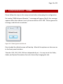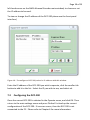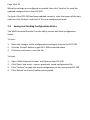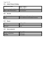
1
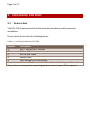
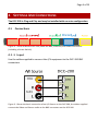
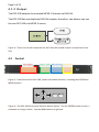
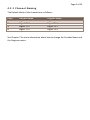
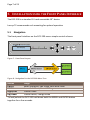
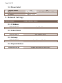
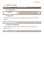
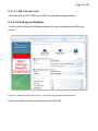
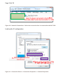
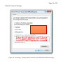
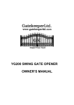
Page 1 of 23
1 TABLE OF CONTENTS
1
TABLE OF CONTENTS
1
2
INTRODUCTION
2
3
UNPACKING THE UNIT
3
4
SETTINGS AND CONNECTIONS
4
5
INSTALLATION USING THE FRONT PANEL INTERFACE
7
6
ADVANCED INSTALLATION
11
7
CONFIGURATION – SNMP
16
8
TECHNICAL SPECIFICATION
20
9
CONTACT INFORMATION
22
Page 2 of 23
2 INTRODUCTION
2.1
Welcome
Thank you for purchasing a Laceys.TV product.
This User Manual contains all the information required for the installation of the
DCC-200. This User Manual also describes the advanced features and settings of
the DCC-200.
2.2
DCC200
The DCC-200 is a high quality MPEG encoder that converts Composite Video and
Stereo Audio to ASI
The DCC200 may be combined with an ASI processor from Laceys.tv for digital
modulation
Figure 1 - The DCC-200 converts up to four Analogue A/V Sources into ASI
Page 3 of 23
3 UNPACKING THE UNIT
3.1
Items in Box
The DCC-200 is delivered with all the necessary hardware and firmware for
installation.
Please check the box for the following items:
Table 1 - List of Items with the DCC-200
Amount
Description
1
DCC – 200 MPEG-2 Encoder
12
BNC to RCA leads
2
BNC to BNC leads
1
Power Cable
1
User Manual (This Document)
1
Software CD (Contains the ‘4 for 1 Encoder Manager’ software)
If any item is missing when unpacking, please contact Laceys.TV for support.
Page 4 of 23
4 SETTINGS AND CONNECTIONS
The DCC-200 is Plug and Play and may be installed with no extra configuration
4.1
Connections
Figure 2 – Photo of back of DCC-200, Show the BNC, Ethernet, and Power Connectors
(Including a Power Switch)
4 . 1 .1 I n p ut
Use the cables supplied to connect the A/V equipment to the DCC-200 BNC
connectors.
Figure 3 - Shows the basic connection of an A/V Source to the DCC-200, the cables supplied
connect the Video and Stereo audio to the BNC connectors on the DCC-200
Page 5 of 23
4 . 1 .2 O u t pu t
The DCC-200 outputs the encoded MPEG-2 Streams via DVB-ASI.
The DCC-200 has two duplicate DVB-ASI outputs; therefore, two devices can use
the one DCC-200 as a MPEG-2 source.
Figure 4 - There are two ASI output on the DCC-200, the second output is a duplicate of the
first.
4.2
Control
Figure 5 - Front Panel of the DCC-200, shows the Button Interface, including the ENTER and
MENU buttons
Figure 6 - The DCC-200 front panel interface button layout. Use the ENTER button to enter a
submenu or change a value. Use the MENU button to go back.
Page 6 of 23
4 . 2 .1 C h an n el N ami n g
The Default labels of the channels are as follows:
Input
1
2
3
4
Provider Name
Digital TV 1
Digital TV 2
Digital TV 3
Digital TV 4
Program Name
Digital TV 1
Digital TV 2
Digital TV 3
Digital TV 4
See Chapter 7 for more information about how to change the Provider Name and
the Program names.
Page 7 of 23
5 INSTALLATION USING THE FRONT PANEL INTERFACE
The DCC-200 is a standard 1U rack mountable 19” device.
Laceys.TV recommends rack mounting for optimal operation
5.1
Navigation
The front panel interface on the DCC-200 uses a simple control scheme.
Figure 7 - Front Panel Layout
Figure 8 - Navigation for the DCC-200 Menu Tree
Button
Usage
ENTER
Enter Sub Menu, Edit Value, Save New Value
MENU
Leave Sub Menu, Cancel Editing
Right/Left
Choose Value
Up/Down
Choose Menu, Change Value
To lock/unlock the DCC-200 hold down both the MENU and ENTER button
together for a few seconds.
Page 8 of 23
5.2
Menu Structure
The following show the complete menu tree of the DCC-200 Front Panel
Interface:
1 . C h an n el : On e, Tw o, T hr ee, F o ur
Menu
Number
Key Name
Default Value
Other Values
1.1. Video Settings
1
2
3
4
5
6
7
Video Standard
Video Available
Resolution
Brightness
Contrast
Saturation
Hue
AUTO
YES
D1
88 (0x58)
145 (0x91)
145 (0x91)
0 (0x00)
PAL, NTSC
NO
HD1, SIF, 2/3D1, 3/4D1
Value out of 255 (HEX)
Value out of 255 (HEX)
Value out of 255 (HEX)
Singed 8bit Value (HEX) -128
to 127
384
48
256, 128
44.1, 32
Layer 2
STEREO
Layer 1
SINGLE CHANNEL, DUAL
CHANNEL, JOINT STEREO
1.2. Audio Settings
1
2
3
4
Audio Bitrate (kbit/s)
Audio Sample Frequency
(kHz)
Audio Layer
Audio ES Mode
1.3. System Settings
1
2
3
4
5
Channel Bitrate (kbit/s)
Video PID
Audio PID
PTM PID
PCR PID
6000
Value from 1000 to 15000
(Different for each channel), leave defaults.
Page 9 of 23
1.4. Muxer Select
1
-
Channel Muxer
P_Name
S_Name
Yes
Digital TV (x)
Digital TV (x)
No
Not Editable, View Only
2 . N et w o r k Set t i n gs
Default Value
Other Values / Notes
2.1. IP Address
192.168.0.136
Any IP address
2.2. Subnet Mask
255.255.255.0
Any Subnet Mask
2.3. Gateway
192.168.0.211
Any Gateway IP address
2.4. Physical Address
xx-xx-xx-xx-xx-xx
Unique and fixed for each unit
Page 10 of 23
3 . T o get h er Set ti n gs
Default Value
Other Values / Notes
3.1. System Bitrate
xxx Mbit/s
Edit the Max output Bitrate for system.
(if set too low the video will chop/corrupt)
3.2. Insert SDT
This option turns on/off function to change the channel names via the SNMP
software.
Yes
No
3.3. Factory Configuration
Select ENTER to reset the DCC-200 to its Factory Defaults, otherwise select
MENU to cancel.
ENTER
MENU
Page 11 of 23
6 ADVANCED INSTALLATION
Once installed, the setup of the DCC-200 is dependent on the level of
configuration required.
6.1
•
For setups with multiple DCC-200 connected to a network (via a switch),
Ethernet connection setup is required.
•
For advanced installations including changing the Channel Names or the
Service Provider Name, use the software supplied on the CD. See
Chapter 7 for more information.
Ethernet Connection
The DCC-200 operates according to the 10BASE-T and 100BASE-TX Ethernet
standards.
To connect to the DCC-200 via Ethernet LAN, (CAT-5e), simply use a crossover
cable or a switch.
6 . 1 .1 Def au l t N etw o r k Set t i n gs
Key
IP Address
Subnet Mask
Gateway
Physical Address
Value
192.168.0.136
255.255.255.0
192.168.0.1
Unique to each unit
Page 12 of 23
6 . 1 .2 LA N C o nn ec t i on
To connect to the DCC-200 over a LAN; use the following procedure:
6.1.2.1 IP Settings on Windows
To edit the IP settings for Windows please first go into Network and Sharing
Centre.
Figure 9 - Network and Sharing Centre, select 'Manage Network Connections'
Select the Ethernet device connected to the DCC-200.
Page 13 of 23
Figure 10 - Network Connections - Select the connection that is connected to the DCC-200
Load up the IP configuration
Figure 11 - Connection Status -> Connection Properties -> Protocol Properties
Page 14 of 23
Edit the Protocol Settings:
Figure 12 - IP settings - Settings shown connect to the DCC-200's default settings.
Page 15 of 23
6 . 1 .3 Sel ec t i n g a I P and Su b n et
The communicating computer only varies its address within the same subnet.
For example, if the DCC-200 has the IP address 192.168.0.136 with the subnet
255.255.255.0 then the computer accessing the DCC-200 must have an IP
address of 192.168.0.xxx, where xxx is any number between 1 and 255 except for
136.
Note: No other device on the same subnet can have the same IP address.
6.2
Control Software
The Control Software is supplied on CD or by E-Mail. The software runs on
Windows XP, Windows Vista, or Windows 7.
No installation needed, simply run the executable from a directory on your
computer.
Figure 13 - Icon of the DCC-200 software
Page 16 of 23
7 CONFIGURATION – SNMP
Please follow the steps in the setup section before attempting the configuration.
On loading “NMS-4channel Encoder,” a message will appear (Fig 6); this message
appears when the software is not yet connected to a DCC-200. Please ignore this
message, and click ok to continue.
Figure 14 - Please Ignore and click ok.
Once loaded the default screen will load up. Most of the options are the same as
in the front panel interface.
The tabs: CH1, CH2, CH3, CH4 are independently set. It is easy to set the Video,
Audio, and System Parameters for each channel by changing the tab.
Page 17 of 23
Figure 15 - Main Setting window for the DCC-200 SNMP configuration software on windows
(NMS-4channel Encoder).
This window allows the configuration of every setting on the DCC-200 other than its IP
address.
Please note, that on some computers the bottom status bar of the NMS4channel Encoder software may not appear. This is typically because the
window is too small. If this happens, please enlarge the window slightly to show
the status bar.
7.1
Operate
To control the DCC-200, connect the PC to the DCC-200 using a crossover
Ethernet cable. Open the Control Software and select the Operate function (top
Page 18 of 23
left hand corner on the NMS-4channel Encoder main window) to choose or set
the IP address to be used.
To view or change the IP address of the DCC-200 please use the front panel
interface.)
Figure 16 – To configure a DCC-200, select its IP address with this window.
Enter the IP address of the DCC-200 you wish to operate, click the smaller tick
button to add it to the list. Select the IP you wish to use, and select ok.
7.2
Configuring the DCC-200
Once the correct DCC-200 is selected in the Operate menu, and click OK. Then
return to the main settings menu and press ‘Refresh’ to load up the current
configuration of the DCC-200. If an error occurs, then the DCC-200 is not
connected to the PC. Please refer to Chapter 6 for more information.
Page 19 of 23
When the settings are configured as needed, then click ‘Confirm’ to send the
updated configuration to the DCC-200.
To check if the DCC-200 has been updated correctly, cycle the power of the unit,
and then click ‘Refresh’ and check if the new configuration loads.
7.3
Saving and Loading Configuration States
The ‘NMS-4channel Encoder’ has the ability to save and load configuration
states.
To Save:
1. Make the changes to the configurations and apply them to the DCC-200
2. Click the ‘Reload’ button to gain DCC-200 formatted values.
3. Click save, and name + save the file.
To Load:
1.
2.
3.
4.
Open ‘NMS-4channel Encoder’ and Operate the DCC-200.
Click ‘Open’ and select + open a previously saved configuration file.
Click ‘Confirm’ to apply the saved configuration to the connected DCC-200
Click ‘Reload’ to check all values were applied.
Page 20 of 23
8 TECHNICAL SPECIFICATION
8.1
Video Input
Connectors
Standard
8.2
Audio Input
Connectors
Standard
Modes
8.3
1x BNC (Left)
1x BNC (Right)
RCA Audio (VMax =755mVpp)
Dual Sound and Stereo Support
MPEG TS Output
Connectors
Standard
Bitrate (Max.)
Bitrate (Effective / Channel)
ASI Mode
Packet size
Return Loss
Impedance
8.4
1x BNC (CVBS)
Composite Video (CVBS)
2x BNC (ASI)
1 ASI stream Duplicated
DVB-ASI output
Complies with EN50083-9 ASI interface
170Mbps
3-15 Mbps
BYTE
188/204 byte
> 10dB
75ohm
Video Channel Coding
Compression Standard
Bitrate
Resolution (MPEG)
Resolution (PAL: Max.)
Resolution (NTSC: Max.)
Compiles to: MPEG-1
MPEG-2 MP@ML(4:2:0)
3-15 Mbps
Full D1, Half D1, SIF, QSIF
720x576
720x480
Page 21 of 23
8.5
Audio Channel Coding
Compression Codec
Audio Sampling Rate (kHz)
Audio Codec Bitrate (kbit/s)
8.6
Control
Front Panel Interface
SNMP
8.7
LCD Display and Navigation Keys
LAN Connection and Windows Software
Power
Voltage
Frequency
Max Load
8.8
MPEG-1 Layer 1
MPEG-1 Layer 2
32, 44.1, 48
128, 256, 384
AC 90 – 260V
50 – 60 Hz
30W
Environmental
Operational Temperature
Storage Temperature
Humidity
-10 to 50°C
-10 to 70°C
10% to 95%
Page 22 of 23
9 CONTACT INFORMATION
LACEYS.TV
Head Office - Seaford
42 Brunel Road
Seaford
Victoria
Australia
3198
Telephone - (03) 9776 9222
Fax - (03) 9776 9766
Email: [email protected]
http://www.laceys.tv/