1
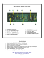
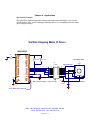
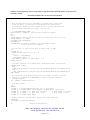
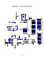
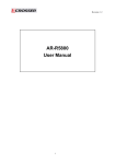
M2- ENGINE
User’s Guide
Table of Contents
Board Overview & Specifications
1
Chapter 1
: Introduction
2
Chapter 2
: Circuit Description
3
Chapter 3
: Operation & Setup
4
Chapter 4
: Applications
5-8
Appendix 1 : Schematic Sheet
9
Disclaimer
10
M2 Engine - Board Overview
56789-
Board Power Supply
5V DC Voltage Regulator
RS232 -TTL Interface IC
Analog to Digital Converter
WiZ232 Microcontroller
1234-
RS232 RJ45 connector
Power ON LED
Connection Headers
Time Base Quartz Crystal
Specifications
•
•
•
•
•
•
•
Serial Interface: EIA RS232 , 9600 to 115200 Bauds
Serial Port Connection: RJ45, 8-positions, 8-contacts
Digital I/O: 24 bits, TTL compatible
Serial Peripheral Interface Port: 3 wires (Serial Clock, Data Input, Data Output)
Analog To Digital Converter: 2 channels, 0-5 VDC, 10-bit
Power Requirements: 7.5 to 12 VDC,100mA
Dimensions (L,W,H): 28.1 x 117.1 x 29 (mm)
#300 - 3665 Kingsway, Vancouver, BC, V5M 5W2, Canada
Phone: 604-299-5173 Fax: 604-299-5174
Page 1 of 11
Chapter 1- Introduction
The M2 Engine has been conceived as an experimentation and ultra low cost serial interface
board. It can help developers, students and electronic designers in general to quickly assemble
a circuit and evaluate its performance.
Not only a complete line of digital interfacing is provided but also analog inputs are available
through the 10 bit on board ADC. Some examples of peripheral devices that can be interfaced
through the M2 are: DC and stepping motors, servomotors, analog sensors, etc.
The M2 becomes a 40-pin module, which can be plugged into any ordinary experimenting
breadboard (not included). The picture at the beginning of this manual shows a board overview
of the M2 module. Several circuits can be tested in sequence by just pulling out the M2 module
from its place and inserting it into another location. No more fussing with 40 wires and the time it
takes to move them around. Application example on chapter 4 of this manual, gives a concrete
idea of how easy is to interface devices to a computer by using the M2.
The M2 Engine contains a WiZ232-A chip that minimizes the hassle associated when
communicating with a PC. For example, should the user wish to place a given value on an 8-bit
port (i.e. PA) then all he or she has to do is to type on a computer terminal program (included):
PWA value [Enter]
where PWA means Write value to Port A and a value that is a number between 0 and 255
The following is a brief description of the WiZ232-A features:
•
•
•
•
•
•
•
•
•
•
Software selectable Baud rate between 9600 and 230400 Bauds.
To send or receive data in either Decimal, Hexadecimal or Binary formats.
Period measurement between 50 and 100000 µsec.
15 - 15000 Hz, 0 - 100% duty cycle Pulse Width Modulation.
Low interrupt recognition through the IRQL pin.
Stepper motor controller port with all the necessary logic for driving steppers in
monophasic, biphasic and half-step stepping modes; linear acceleration and
deceleration capability, stepping speed between 16 and 8500 step/sec. Emphasis
has been placed in making the stepper interface easy to use and furnished with
external control signals such as trigger, pause and stop.
A 1 keystroke “Again’ command to repeat the previous command.
Direct reading of industry standard Serial A to D converters (8,10 and 12 bits).
Four channels for reading relative resistance or capacitance.
A configuration report feature which sends the active configuration of any parallel
port, the PWM or the stepper motor parameters back to the terminal.
Please refer to the WiZ232-A User Guide for more information about these features. It
can be downloaded free from htpp://www.rmv.com
The M2 Engine works equally well with a Mac®, an Apple® II (with a serial port) or an IBM
compatible (XT or higher).
#300 - 3665 Kingsway, Vancouver, BC, V5M 5W2, Canada
Phone: 604-299-5173 Fax: 604-299-5174
Page 2 of 11
Chapter 2 - Circuit Description
Appendix 1 of this manual, shows the schematic sheet of the M2 Engine.
Power Supply
The RS232 protocol requires a voltage between -3 V and -15 V to represent a logic 1. In order to
generate those levels a standard charge pump IC provides these voltages and the corresponding
line driver and receiver for the serial port link. A 5V, 1A series regulator provides a safe and reliable
DC power supply for all the logic on board and can supply power to the external circuitry connected
to the M2. A suitable power supply for the M2 is a 9 Volts wall transformer with a current capacity of
300 mA or more (depending on the power consumption of the external circuitry. Some applications
may require the use of a heat sink (not provided) for the 5-Volt voltage regulator IC).
Serial Link
An eight contact 8 positions RJ45 connector provides the way for connecting the serial port to
the computer, using a RJ45 to RJ45 cable. A RJ45 to DB-9 adapter interfaces this cable to the
DB-9 female port on the computer.
WiZ232-A Section
The rest of the circuit corresponds to the standard WIZ232-A configuration. 10K ohms resistors
pull up IRQ (also known as IRQL) and PD5 pins, while another 10K resistor pulls down PD4 pin.
The reset circuit on pin 1 works as follows: when power is applied, C3 is discharged. Thus, it
represents a low impedance path to ground until it is charged to a given voltage through R2. The
time constant is long enough to assert the reset condition. To reset the M2 module, the RESET
command can be issued directly from the computer or the RESET pin (located on HDR1-pin 1)
can be pulled-down to ground for a least 10ms.
AD converter section
The M2 uses a serial interface 2-channel, 10-bit resolution, Analog to Digital converter (ADC).
It provides a handy way of getting analog readings from sensors or analog devices such as
potentiometers. Voltage reference for this ADC is taken from the on-board 5V regulator.
The 32-bit DLL provides a function for reading this ADC.
#300 - 3665 Kingsway, Vancouver, BC, V5M 5W2, Canada
Phone: 604-299-5173 Fax: 604-299-5174
Page 3 of 11
Chapter 3 – Operation & Setup
Operation
You can explore the functionality of the M2 module using the terminal emulation program
provided on the disk (TTY.EXE). Otherwise, you can type commands from a terminal program or
run a program written in the language of your choice. A 32-bit DLL is available for Windows
95/98/NT, which is used by the DEMOM2 .EXE (written in C++, source code available) and the
Visual Basic Demo program (source code available). With these tools is very easy to start to
target any projects.
It should be noted that the pin strips can be used not only to connect the M2 module to an
experimenter breadboard, but also to suitable female connectors on a target printed circuit
board. Thus, the M2 module can be used as a complete communication unit to the computer,
which can be plugged into place, just the same way as an IC or a hybrid circuit would be.
If the M2 module is to be used in a permanent application, solder the control lines directly to the
pads rather than using the pin strips.
To quickly get into commanding ports, hook up an LED in series with a 1K resistor to PA. Type
PCA 255 [Enter] to configure all pins of PA as outputs. Type PWA 1 [Enter] or PWA 4 [Enter] to
turn the LED ON or OFF respectively.
To read PB, place a 10K resistor from PB4 to ground or to VCC and type PRB [Enter]. For more
details, refer to the WIZ232-A User Guide.
Set Up
•
•
•
Without applying power to the M2 unit, connect the serial cable to the computer’s serial port.
Load a terminal program into your computer. The diskette provided contains the
ITCTTY.EXE program for DOS. Set up the COM port in the program by using the F1 key.
Select the port number to which the M2 is connected, 9600 Bauds, N, 8,1 (no parity, 8-bit, 1
stop bit). On most computers, COM2 is a DB25 connector and COM1 is a DB9.
Apply power to the board. (The tip of the power supply plug should be + 12 V.) The LED
should be ON. You should see the “WiZ232A - Ver x.xx Electronics Inc.” message appearing
on your screen.
#300 - 3665 Kingsway, Vancouver, BC, V5M 5W2, Canada
Phone: 604-299-5173 Fax: 604-299-5174
Page 4 of 11
Chapter 4 - Applications
Application Example
The figure below shows an application example that interfaces the M2-Engine to a 6 or 5-wire
unipolar stepper motor. It uses a Darlington transistor array IC (U1: ULN2803) which can handle
up to 1 Amp per winding.
Six Wire Stepping Motor IC Driver
M2-ENGINE
S3
STOP
+5V
RESET
IRQL
PA7
PA6
PA5
PA4
PA3
PA2
PA1
PA0
PB7
PB6
PB5
PB4
PB3
PB2
PB1
PB0
GND
+5V
XOUT
PWM
CIN
PD7
PD5
SCK
SPDO
SPDI
AD1
AD0
PC7
PC6
PC5
PC4
PC3
PC2
PC1
PC0
GND
+9V
GND
RX232
TX232
GND
+12V
S1
LEFT LIMIT
S2
RIGHT LIMIT
6 wire Stepper Motor
U1
ULN2803
1
2
3
4
5
6
7
8
9
R1
10K
In1
In2
In3
In4
In5
In6
In7
In8
G
Out1
Out2
Out3
Out4
Out5
Out6
Out7
Out8
K
Stepper Winding 1
18
17
16
15
14
13
12
11
10
+12V
Max current per winding : 1 Amp. / 30 V DC
C1
100uF/50V
TO THE SERIAL PORT CONNECTOR
#300 - 3665 Kingsway, Vancouver, BC, V5M 5W2, Canada
Phone: 604-299-5173 Fax: 604-299-5174
Page 5 of 11
+
Stepper Winding 2
Software for this application can be easily written using Microsoft® MS-DOS Qbasic, as shown in the
following example:
PROGRAM LISTING FOR THE APPLICATION EXAMPLE
'
'
'
'
This program shows how to implement an stepper motor controller
using the built in functions on the WiZ232-A microcontroller.
For further references using stepper motors, consult the WiZ232-A
user’s manual available from http://www.rmv.com
' *** PROGRAM BEGINS HERE ***
CONST ZeroPos = 8388608 ' used for Shaft Position display
CLS
Start:
PRINT "Apply power to the M2 (or reset it) and press a key to start"
WHILE INKEY$ = "": WEND
ON ERROR GOTO ResumeError
ResumeError:
RESUME NEXT 'Otherwise, holding a key down might result
'in an I/O error from QBasic
' Let the user to select which port to open, COM1 or COM2
DO
LOCATE 10, 10
PRINT "Select COM port (1) (2): ";
DO
comport = VAL(INKEY$)
LOOP WHILE comport = 0
LOOP WHILE comport <> 1 AND comport <> 2
PRINT comport
' Now open COM Port as selected with a 2048-byte buffer in Tx and Rx
SELECT CASE comport
CASE 1
OPEN "COM1:9600,N,8,1,CD0,CS0,DS0,OP0,RS,TB2048,RB2048" FOR RANDOM AS #1
CASE 2
OPEN "COM2:9600,N,8,1,CD0,CS0,DS0,OP0,RS,TB2048,RB2048" FOR RANDOM AS #1
END SELECT
' Set the WiZ232-A in program mode with <C>onfigure <R>esults <A>SCII
' <P>rogram, required for READSERIAL in order to decode incoming
' strings properly.
W$ = "CRAP": GOSUB WriteSerial
' Show Main Screen
CLS
PRINT
LOCATE 5, 5: PRINT "RMV Electronics Inc.-*- M2 Engine"
LOCATE 6, 5: PRINT "Application Example: Stepper Motor Controller"
LOCATE 10, 5: PRINT " L: Move Left 100 steps
R: Move Right 100 steps,"
LOCATE 11, 5: PRINT " l: Move left 1 step
r: move rigth 1 step"
LOCATE 12, 5: PRINT "Esc: Exit"
' Enable timer for automatically showing the shaft position
TIMER ON
ON TIMER(1) GOSUB ShowPosition
DO
' Main Loop begins here
#300 - 3665 Kingsway, Vancouver, BC, V5M 5W2, Canada
Phone: 604-299-5173 Fax: 604-299-5174
Page 6 of 11
DO
' Wait for a user keystroke
K$ = INKEY$
LOOP WHILE K$ = ""
WHILE WaitMotor = 1: WEND ' or if motor is busy
SELECT CASE K$
CASE "R"
PLAY "O3C16F64"
M$ = "SH+500;800;1;200"
K$ = ""
CASE "r"
M$ = "SH+1;800;1;200"
K$ = ""
CASE "L"
PLAY "O3F16C64"
M$ = "SH-500;800;1;200"
K$ = ""
CASE "l"
M$ = "SH-1;800;1;200"
K$ = ""
CASE CHR$(27)
CLOSE : END
END SELECT
' process user's requirement
' move 500 steps CW or right
' move 1 step CW or right
' move 500 steps CCW or left
' move 1 step CW or left
' End pressing Esc
IF K$ = "" THEN
'Get motor status and check motion completed
'if status OK (=1) send motion command
'PortBusy acts as semaphore for using the serial port
W$ = "S?"
PortBusy = 1: GOSUB WriteSerial
'V returns the status of the motor: V=1 Motor ready to accept commands
IF V = 1 THEN W$ = M$: GOSUB WriteSerial
PortBusy = 0
END IF
LOOP 'Main Loop ends here
'** SUBROUNTINES **
ShowPosition:
' Displays the shaft's position and motor status once every second
IF PortBusy = 0 THEN
W$ = "S?": GOSUB WriteSerial
MotorStatus = V
W$ = "SN": GOSUB WriteSerial
SELECT CASE V
CASE IS < 0
LOCATE 16, 10
PRINT "Motor Disabled"
CASE IS > ZeroPos
Position = ZeroPos - V
CASE IS < ZeroPos
Position = V
END SELECT
IF V >= 0 THEN
IF MotorStatus = 1 THEN WaitMotor = 0 ELSE WaitMotor = 1
LOCATE 15, 10: PRINT "Shaft Position:"; : PRINT USING "########"; Position
W$ = "S?": GOSUB WriteSerial
LOCATE 16, 10: PRINT " Motor Status: ";
IF MotorStatus = 1 THEN PRINT "Idle " ELSE PRINT "Moving"
#300 - 3665 Kingsway, Vancouver, BC, V5M 5W2, Canada
Phone: 604-299-5173 Fax: 604-299-5174
Page 7 of 11
END IF
END IF
RETURN
' Write command to serial port. Returns the value fetched from the
' WiZ232-A in V (in case of error legend is returned in ERRORCODE$)
WriteSerial:
' WARNING: When the WiZ232-A is not working in program mode
' (command=CRAP[CR]), it returns CR and LF which prevent READSERIAL
' below to fetch function values properly. Thus,
' ALWAYS do W$="CRAP":GOSUB WRITESERIAL at the onset
REM PRINT W$; ' Remove REM to see the commands on the screen
PRINT #1, W$ ' Send the string out (PRINT automatically adds a CR)
GOSUB READSERIAL ' and then fetch the response from the WiZ232-A
RETURN
' Reading serial port. NEVER call this routine directly
READSERIAL:
S$ = ""
IF LOC(1) = 0 THEN GOTO READSERIAL ' Loop until a character is received
' Get received string into S$
Lp1:
C$ = INPUT$(1, #1)
' Fetch from the COM buffer one character at the time
S$ = S$ + C$
' and add it at the end of string$ S$
IF C$ <> ">" THEN GOTO Lp1 ' ">" is always sent last by WiZ232-A
REM PRINT S$ ' Remove REM to see the strings returned on the screen
'Decode string (V$) and value (V)
VALIDERROR = TRUE
ERRORCODE$ = ""
V$ = ""
FOR H = 1 TO LEN(S$)
IF MID$(S$, H, 1) = CHR$(7) THEN VALIDERROR = FALSE
IF MID$(S$, H, 1) = "?" THEN ERRORCODE$ = MID$(S$, H + 1, 1)
NEXT H
IF (VALIDERROR = TRUE AND ERRORCODE$ <> "") THEN GOSUB ERRORSUB: RETURN
V$ = ""
FOR n = 1 TO LEN(S$)
x$ = MID$(S$, n, 1) ' Get rid of CR and LF if any
IF x$ <> CHR$(13) THEN IF x$ >= "0" AND x$ <= "9" THEN V$ = V$ + x$
NEXT n
' V$ = LEFT$(V$, LEN(V$) - 1) ' Get rid of the '>'
V = VAL(V$)
' and save results
RETURN
ERRORSUB:
V = -1 ' this allows the program to handle the error
RETURN
'*** PROGRAM ENDS HERE ***
#300 - 3665 Kingsway, Vancouver, BC, V5M 5W2, Canada
Phone: 604-299-5173 Fax: 604-299-5174
Page 8 of 11
Appendix 1 - M2 Schematic Sheet
+5
R2
200K
C6
27pF
RESET
C5
27pF
X1
C3
0.1uF
+5
C2
0.1uF
7.3728 MHz
3
44
+5
R9
R3
+5
XO
43
42
RESET
IRQ
1
2
OSC1
OSC2
RST
IRQ
10K
1K
VPP
VDD
R1
10M
D1
LED
U1
LM7805
1
VI
2
C1
0.1uF
3
VO
C7
22uF/16V
R5
+5
10K
PD7
PWM
PD5
SCK
SPIDOUT
SPIDIN
TXDATA
RXDATA
40
38
37
36
35
34
33
32
CIN
41
PD7
PWM
PD5/SS
PD4/SCK
PD3/MOSI
PD2/MISO
TX
RX
VSS
+12
1
2
+5
GND
POWER1
CIN
PA0
PA1
PA2
PA3
PA4
PA5
PA6
PA7
PB0
PB1
PB2
PB3
PB4
PB5
PB6
PB7
PC0
PC1
PC2
PC3
PC4
PC5
PC6
PC7
12
11
10
9
8
7
6
5
PA0
PA1
PA2
PA3
PA4
PA5
PA6
PA7
13
14
15
16
18
19
20
21
PB0
PB1
PB2
PB3
PB4
PB5
PB6
PB7
31
30
29
28
27
26
25
24
PC0
PC1
PC2
PC3
PC4
PC5
PC6
PC7
+5
C12
C10
10uF
16
.1uF
U2
WZ232-PLCC
22
+5
CON8
3
4
C9
5
10uF
14
13
7
8
+5
C11
10uF
SCK
C2TO1
RI1
TO2
RI2
U4
TI1
RO1
TI2
RO2
C4
0.1uF
8
2
6
C1C2+
GND
1
2
3
4
5
6
7
8
10uF
V+
V-
11
12
TXDATA
RXDATA
R4 SPIDIN
10K
SPIDOUT
10
9
7
6
5
U3
VCC
CS
SCK
CH0
DOUT
CH1
DIN
GND
1
PD7
2
ADCH0
3
ADCH1
4
RESET
IRQ
PA7
PA6
PA5
PA4
PA3
PA2
PA1
PA0
PB7
PB6
PB5
PB4
PB3
PB2
PB1
PB0
1
2
3
4
5
6
7
8
9
10
11
12
13
14
15
16
17
18
19
20
20PIN
+5
HDR2
1
XO
2
PWM
3
CIN
4
PD7
5
PD5
6
SCK
7
SPIDOUT 8
SPIDIN
9
ADCH1
10
ADCH0
11
PC7 12
PC6 13
PC5 14
PC4 15
PC3 16
PC2 17
PC1 18
PC0 19
20
SP8537
20PIN
15
CON1
C1+
VCC
C8
1
HDR1
+5
ADM232LJR
#300 - 3665 Kingsway, Vancouver, BC, V5M 5W2, Canada
Phone: 604-299-5173 Fax: 604-299-5174
Page 9 of 11
DISCLAIMER
PLEASE READ THIS CAREFULLY:
RMV ELECTRONICS INC. does not assume any liability arising from the application and/or use of the
product/s described herein. RMV ELECTRONICS INC. products are not authorized for use as
components in medical, life support or military devices without written permission from RMV
ELECTRONICS INC. The material enclosed in this package may not be copied, reproduced or imitated in
any way, shape or form without the written consent of RMV ELECTRONICS INC. This limitation also
applies to the firmware that the Integrated Circuits in this package might contain.
WARRANTY: RMV ELECTRONICS INC. will replace, free of charge, faulty components in this package with the
exception of the Integrated Circuits it might contain, for a period of 6 months after the date of purchase.
#300 - 3665 Kingsway, Vancouver, BC, V5M 5W2, Canada
Phone: 604-299-5173 Fax: 604-299-5174
Page 10 of 11