1
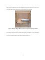
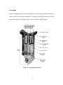
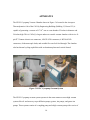
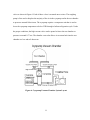
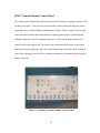
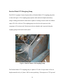
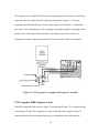
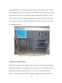
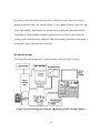
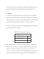
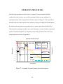
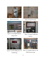
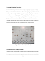
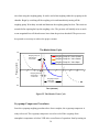
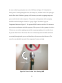
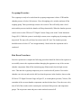
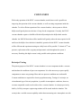
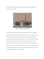
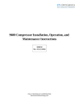
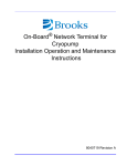
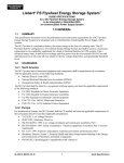
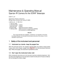
29" Cryopump Vacuum Chamber
California Polytechnic State University
San Luis Obispo
- Senior Project -
i
Operation of the HVEC Cyropump Vacuum
Chamber and
Resistojet Testing
Allen L. Victor
Oliver B. Martin
California Polytechnic State University
San Luis Obispo
Submission to:
Aerospace Engineering Department
Robert E. Kennedy Library
June 12, 2001
ii
Statement of Disclaimer
Since this project is a result of a class assignment, is has been graded and accepted as
fulfillment of the course requirements. Acceptance does not imply technical accuracy or
reliability. Any use of information in this report is done at the risk of the user. These risks
may include catastrophic failure of the device or infringement of patent or copyright laws.
California Polytechnic Sate University at San Luis Obispo and its staff cannot be held liable
for any use or misuse of the project.
iii
TABLE OF CONTENTS
TABLE OF FIGURES ...............................................................................................vi
Acknowledgements .................................................................................................1
Abstract.....................................................................................................................2
Introduction ..............................................................................................................3
HVEC Vacuum Chamber Theory.............................................................................6
ROUGHING PUMP.................................................................................................................... 6
CRYOPUMP ............................................................................................................................. 8
Apparatus ...............................................................................................................10
HVEC VACUUM CHAMBER CONTROL PANEL...................................................................... 12
GOULD MICRO 84 PROGRAMMABLE CONTROLLER .............................................................. 13
DUOSEAL MODEL 1374 ROUGHING PUMP ........................................................................... 14
CTI-CRYOGENICS CRYO-TORR 8 CRYOPUMP ...................................................................... 15
CTI-CRYOGENICS 8200 COMPRESSOR UNIT ........................................................................ 16
VARIAN AIR ACTUATED VALVES ......................................................................................... 17
ELECTRICAL SYSTEM ........................................................................................................... 19
Assembly ................................................................................................................21
ROUGHING PUMP.................................................................................................................. 21
PNEUMATIC VALVES ............................................................................................................ 22
COMPRESSOR ....................................................................................................................... 23
iv
Operation Procedures ...........................................................................................26
INITIALIZATION PROCESS ..................................................................................................... 27
CRYOPUMP ROUGHING PROCEDURES ................................................................................... 29
THE MARTIN-VICTOR CYCLING PROCEDURE ....................................................................... 29
CRYOPUMP COMPRESSOR PROCEDURES ............................................................................... 30
EXPERIMENT LOADING PROCEDURES ................................................................................... 32
CHAMBER ROUGHING PROCEDURE ...................................................................................... 32
CRYOPUMP PROCEDURE ....................................................................................................... 33
SHUT DOWN PROCEDURES ................................................................................................... 33
DIMENSIONAL TESTING REQUIREMENTS .............................................................................. 34
Maintenance ...........................................................................................................35
ROUGHING PUMP MAINTENANCE ......................................................................................... 35
Oil Change ...................................................................................................................... 36
CRYOPUMP MAINTENANCE .................................................................................................. 36
Adsorber Replacement .................................................................................................... 36
Adding Helium Gas ......................................................................................................... 37
Conclusion..............................................................................................................38
RESISTOJET TESTING ............................................................................................................ 38
Bibliography ...........................................................................................................41
Appendix A – Operating Procedures....................................................................42
v
TABLE OF FIGURES
Figure 1. HVEC Vacuum Chamber Setup with Compressor (shown without belljar) ............. 3
Figure 2. Resistojet Engine Built by Cal Poly Aerospace Engineering Students ..................... 5
Figure 3. Schematic Diagram of the Vacuum System for the Roughing Pump........................ 6
Figure 4. Cryopump Architecture ............................................................................................. 8
Figure 5. HVEC Cyropump Vacuum System ......................................................................... 10
Figure 6. Cryopump Vacuum Chamber System Layout ......................................................... 11
Figure 7. Cryopump Vacuum Chamber Control Panel ........................................................... 12
Figure 8. Gould Micro 84 Programmable Controller.............................................................. 13
Figure 9. DuoSeal Model 1374 Roughing Pump .................................................................... 14
Figure 10. Cryo-Torr 8 High-Vacuum Cryopump .................................................................. 15
Figure 11. CTI-Cryogenics Cryopump and Compressor Assembly ....................................... 16
Figure 12. CTI-Cryogenics 8200 Compressor Unit ................................................................ 17
Figure 13. Pneumatic Diagram of Varian Valves ................................................................... 18
Figure 14. Electrical Diagram of Major Components in HVEC Vacuum Chamber............... 19
Figure 15. Roughing Pump Connected to Vacuum Chamber................................................. 22
Figure 16. CIT-Cryogenics 8200 Compressor and Major Connections.................................. 24
Figure 17. Cryopump Vacuum Chamber Operation Sequence............................................... 26
Figure 18. Power Main............................................................................................................ 28
Figure 19. Air pressure valve .................................................................................................. 28
Figure 20. Varian Digital Ionization Gauge Control............................................................... 28
Figure 21. Cryogenic Temperature Indicator.......................................................................... 28
vi
Figure 22. Granville-Phillips Series 275 Vacuum Gauge ....................................................... 28
Figure 23. Cryopump Compressor Unit Helium Pressure Gauge........................................... 28
Figure 24. Control Panel (Switch Board)................................................................................ 29
Figure 25. The Martin-Victor Cycle ....................................................................................... 30
Figure 26. Water Coolant Valve Turning 180° ....................................................................... 31
Figure 27. Dimensions for the HVEC Vacuum Chamber....................................................... 34
Figure 28. Resistojet Setup on Platen...................................................................................... 39
vii
ACKNOWLEDGEMENTS
We would like to thank Dan Powell, whose tremendous effort is greatly appreciated. Dan
Powell helped install a pressure tap for the valve actuators, lifted and lowered the belljar with
a forklift when needed, and welded a broken pipe. Also, Dan Powell provided the power
connections for the compressor and vacuum chamber, and he set up the resistojet power
connections for future testing. As can be seen, without the help of Dan Powell, this senior
project would not be possible.
We would also like to thank Dr. Dianne DeTurris for providing moral and financial support
to further the installation of the vacuum chamber.
1
ABSTRACT
The High Vacuum Equipment Corporation (HVEC) Vacuum Chamber donated from
Stanford University was installed into the Thermodynamics Laboratory of the Aerospace
Engineering Department at Cal Poly, San Luis Obispo. Installation and operating procedures
are described, and diagrams of the system are included. The HVEC Vacuum Chamber uses a
roughing pump and CryoTorr cyropump to achieve high vacuum limit pressure of 6.7 x 10⁻⁶
torr. The vacuum chamber can hold components up to 29 inches in length and 2 feet in
height. The shroud and platen allow for thermal cooling capability to simulate space
conditions by running nitrogen around the belljar and at base of the test stand. Included
guidelines on maintenance for the HVEC describe the optimum operating conditions for the
components. A resistojet engine was placed inside the vacuum chamber for electric
propulsion testing, and a hoist for the belljar of the vacuum chamber will be installed in the
near future.
2
INTRODUCTION
The HVEC Vacuum Chamber was donated from the Aeronautics and Astronautics
Department of Stanford University. A compressor for the vacuum chamber, required for
running the cryopump, was not included, and the major components of the system were not
assembled. Installation of the Vacuum Chamber began in October of 2000 inside the
Thermodynamics Lab of the Aerospace Engineering Department at Cal Poly. The Vacuum
Chamber’s last use was in 1997, therefore, it was possible that components were not in
working condition when received from Stanford University. Installation of the HVEC
Vacuum Chamber was completed in March of 2001. Figure 1 shows the HVEC Vacuum
Chamber System.
Figure 1. HVEC Vacuum Chamber Setup with Compressor (shown without belljar)
3
The Vacuum Chamber works through the use of two pumps, the roughing pump and the
CryoTorr cryopump. The roughing pump brings the pressure of the vacuum chamber to 150
mtorr, while the cryopump continues to decrease the pressure to 6.7 µTorr. Operation of the
roughing pump lasts for approximately 30-40 minutes. The length of time necessary for the
roughing pump to reach the required pressure can be decreased through Martin-Victor
cycling. Martin-Victor cycling is a custom procedure to decrease the pressure limit by
partially re-pressurizing the chamber and running the roughing pump to achieve a lower
limit. The cryopump, on the other hand, can require up to 6 hours to reach its highest vacuum
state.
Vacuum chambers are valuable to Aerospace Engineering research to simulate the conditions
of low earth orbit space. Although the pressure of space is several orders of magnitude less
than what the HVEC Vacuum Chamber can achieve, preliminary testing for out gassing and
pneumatic sealing can be done. The chamber is also good for materials testing as well.
Advanced space propulsion, such as electric propulsion, requires the use of a vacuum to
attain accurate results since this best simulates the environment electric propulsion engines
operate in. A resistojet engine is the first electric thruster to be tested inside the HVEC
vacuum chamber.
Figure 2 displays the Resistojet Engine in the setup to be put inside the chamber. Resistojets
are an electrothermal type of electric propulsion. They are primarily used for orbit
maintenance on large spacecraft. The engine incorporates a heater to increase the pressure of
the air within the engine. As the current to the engine is increased, the temperature of the
4
heater inside the engine increases, and subsequently, the pressure increases. A nozzle at the
end of the engine releases the pressure and forms thrust for the resistojet.
Figure 2. Resistojet Engine Built by Cal Poly Aerospace Engineering Students
Successfully testing the resistojet validates the capability of the HVEC Vacuum Chamber to
test electric propulsion engines under space-simulated conditions.
5
HVEC VACUUM CHAMBER THEORY
To achieve a high vacuum (10-6 torr) in the chamber, two stages of pressure reduction are
involved. First a roughing pump is used as a fore pump to produce the necessary fore vacuum
for which the cryopump can operate in. The roughing pump reduces the pressure to
approximately 150 mtorr while the cryopump continues to reduce the pressure to 6.7 µtorr.
Roughing Pump
The DuoSeal 2-stage roughing pump reduces pressure by steadily and consistently removing
a portion of the original volume of gas contained in an enclosed vessel. The action of the
rotating elements in the pump allow for the expansion and contraction of a given space.
Figure 3 shows a schematic diagram of the roughing vacuum system.
Figure 3. Schematic Diagram of the Vacuum System for the Roughing Pump
This expansion compression space (shaded area) is vacuum tight. As the shaft spins, the
volume increases due to the outside radial geometry. The pressure in this space consequently
decreases below that of the chamber, therefore, the gas travels through the inlet connection
6
from the chamber into the expansion/compression space. As the shaft spins further, the
expansion/compression volume decreases and the air is compressed. The air pressure exceeds
atmospheric pressure, and escapes the system through the exhaust port. After the shaft has
rotated 180°, the pneumatically sealed vanes switch sides allowing for the pressure reduction
described above to occur twice during once cycle.
As the pressure in the vessel is decreased with successive cycles, the amount of gas put into
the volume (1) also steadily diminishes. Since the gas must be compressed back to
atmospheric pressure to be released through the exhaust valve, a pressure somewhat greater
than atmospheric pressure is required to open the exhaust valve. The pump can only remove
a small fraction of the remaining gas in the chamber, so it is impossible for all the gas to be
removed. Also, many of the components of the system such as the vacuum pump, the
vacuum chamber, and the necessary connections between contain a minute amount of
leakage that is impossible to seal. Therefore, a state of equilibrium is eventually reached,
such that the leakage balances the amount of gas expelled by the pump. This is known as the
blank-off or ultimate pressure of the pump.
The ultimate pressure for the roughing pump was experimentally found to be approximately
100 mtorr. Since further pressure reduction is required to achieve a high vacuum in the µtorr
range, a cryopump operates to further reduce pressure.
7
Cryopump
After the roughing pump has lowered the pressure to 150 mtorr, the cryopump continues to
reduce pressure several orders of magnitude. Cryopumps (as the name implies) freeze gases
into solids, therefore, reducing the vapor pressure resulting in a high vacuum.
Figure 4. Cryopump Architecture
8
Figure 4 displays the cryopump architecture. The cryopump operates by use of a compressor,
which supplies helium to the cold head. The helium undergoes a refrigeration cycle to cool
specifically designed surfaces to 80K and 15K. The 80K surface condenses water vapor, the
bulk of the gas load, whereas the 15K surface condenses the majority of the remaining gases.
When the gases are condensed to a solid, the vapor pressure falls below 10-12 torr. Noncondensable gasses, such as helium, hydrogen, and neon, are simultaneously adsorbed to 15K
by a bed of charcoal granules.
The capturing and freezing out of gas molecules is similar to how a refrigerator works.
Helium, the refrigerant, is compressed, cooled, and allowed to expand. The expansion occurs
due to heat exchange from the condensation of air molecules to the helium gas. Hydrogen,
neon, and helium (from the chamber) are non-condensable, and therefore, require the 15K
cryo-adsorbing array for adsorption. There is an enormous surface area available for the noncondensing gases to accumulate within. The capacity of hydrogen the cryo-adsorbing array
can handle determines the regeneration cycle for the cryopump. When the pump is saturated
with hydrogen, the pressure will rise again, and the captured gas must be removed.
Regeneration refers to the heating of the components to remove all the non-condensable
gases. To regenerate the cryopump, the compressor is turned off, and the atmospheric heat
automatically warms the cyropump back to room temperature within two hours.
9
APPARATUS
The HVEC Cryopump Vacuum Chamber shown in Figure 5 is located in the Aerospace
Thermodynamics Lab of the Cal Poly Engineering Building (Building 13, Room 125) is
capable of generating a vacuum of 6.7⋅10-6 torr to a test chamber 25 inches in diameter and
24 inches high. This is Cal Poly’s largest and most versatile vacuum chamber with its six 41pin ITT Cannon electric test connectors, 6 RG58 #708 connectors, 6 RG58 #859D
connectors, 40 thermocouple leads, and variable flow rate fuel feed-through. The chamber
also has thermal cycling capabilities with an aluminum platen and vertical shroud.
Figure 5. HVEC Cyropump Vacuum System
The HVEC Cryopump vacuum system operates in the same manner as most high vacuum
systems like oil- and mercury-vapor diffusion pumps, getters, ion pumps, and getter-ion
pumps. These systems consist of a roughing pump and a high vacuum pump with a series of
10
valves as shown in Figure 6. Each of these valves is actuated one at a time. The roughing
pump is first used to displace the majority of the air in the cyropump and in the test chamber
to pressures around 100 microns. The cryopump requires a compressor unit that is used to
lower the cyropump temperature to below 25°K through a helium refrigeration cycle. Under
the proper conditions, the high vacuum valve can be opened to lower the test chamber to
pressure to around 10-6 torr. The chamber vent value allows air to return back into the test
chamber at a low and safe burst rate.
Figure 6. Cryopump Vacuum Chamber System Layout
11
HVEC Vacuum Chamber Control Panel
The control panel switches that are used to electrically control the two pumps and four valves
are shown in Figure 7. There are only seven switches on this control panel that are used to
operate the entire vacuum chamber without thermal control. These switches are all located
across the bottom of the panel and include the roughing pump switch, cryopump switch,
chamber rough valve switch, cryopump rough valve switch, and the high-vacuum valve
switch in order from right to left. The last two are on the bottom left corner of the control
panel and include the chamber vent valve switch and the trap switch that will be discussed
more in the operating procedures. The cryopump compressor is a separate unit and requires
manual operation.
Figure 7. Cryopump Vacuum Chamber Control Panel
12
Gould Micro 84 Programmable Controller
All of the switches are wired through the Gould Micro 84 Programmable Controller, shown
in Figure 8, in order to prevent delinquent component operation. This controller only allows
one valve to be open at a time with a 15 second delay on the chamber roughing valve. It also
prevents the cryopump from turning on and the high vacuum valve from opening if the
proper pressures and temperatures do not exist in cryopump and the test chamber. The
cryopump compressor unit is operated manually so extra care must taken to be used only at
the appropriate times. If the compressor is turned on while the pressure inside the cryopump
is too high, condensation will occur and damage the cryopump. Follow the operating
procedures in Appendix A to avoid these problems.
Figure 8. Gould Micro 84 Programmable Controller
13
DuoSeal Model 1374 Roughing Pump
The HVEC Cryopump Vacuum System utilizes a DuoSeal Model 1374 roughing pump that
is shown in Figure 9. This roughing pump operates under molecule displacement theory
using a rotating piston and oil sealant and is capable of creating vacuums in the low millitorr
range (95%-99% of the air). The roughing pump is used to lower the pressure in the
cryopump to 150 microns and 100 microns in the test chamber and is operated using the
roughing pump switch on the control panel.
Figure 9. DuoSeal Model 1374 Roughing Pump
The DuoSeal Model 1374 roughing pump is capable of 23 cubic feet per minute of free-air
displacement driven by a 3-phase, 200Vac motor producing 1.5 horsepower at 1725 rpm and
14
a pump rotational speed of 510 rpm. This two-stage pump has a “vacuum pump oil” capacity
of 1.25 quarts and a net weight of 218 lbs.
CTI-Cryogenics Cryo-Torr 8 Cryopump
The CTI-Cryogenics Cyro-Torr 8 High-Vacuum Cryopump shown in Figure 10 provides
fast, clean pumping of all gases between 10-3 and 10-10 torr. It operates by condensing and
holding gases at extremely low temperatures (below 25°K) and producing very low vapor
pressures. So far, this cryopump has created a vacuum of 6.7⋅10-6 torr inside the test chamber.
Figure 10. Cryo-Torr 8 High-Vacuum Cryopump
15
The cryopump itself weighs 45 lbs and is powered through the cold head power and helium
supply lines that are connected to the compressor and shown in Figure 11. Since the
cryopump traps and holds the gases, it has a finite capacity of 1000 liters of condensable
gases and 3 liters of hydrogen gas. The cryopump is operated through the cryopump switch
located on the control panel and is activated via the high vacuum valve switch. The
cryopump can handle a maximum gas burst of 150 torr-liters but 100 is recommended.
Figure 11. CTI-Cryogenics Cryopump and Compressor Assembly
CTI-Cryogenics 8200 Compressor Unit
The 8200 Compressor Unit shown in Figure 12 was purchased from CTI-Cryogenics during
winter quarter of 2001. The compressor is water cooled and used to supply a source of
compressed helium to the cryopump that powers a refrigeration cycle and lowers the
16
cryopump temperature. The helium supply must maintain a static pressure of 245-255 psig
and an operational pressure of 270-290 psig. These conditions can be monitored on the gauge
mounted to the compressor. The compressor weights 140 lbs and is powered by a 3-phase,
208Vac, 60Hz source. The compressor is manually operated but should only be used when
the cryopump is at or below 150 microns and the water coolant is turned on as described in
the operating procedures.
Figure 12. CTI-Cryogenics 8200 Compressor Unit
Varian Air Actuated Valves
The HVEC Cryopump Vacuum Chamber system uses four Varian air actuated, forged brass
body bellow-sealed valves to maintain the pressure differentials. The four different valves are
shown in the pneumatic diagram in Figure 13 as well as the vacuum chamber layout in
Figure 6. The chamber vent valve and the cryopump roughing valve are both Model 1252
17
and the chamber rough valve and high vacuum valve are Model 1253. These valves
incorporate a normally closed, air opening, spring closing design so the valve will
automatically close during a power failure or loss of actuating air. The required actuating air
pressure is between 65 psig and 80 psig.
Rotate
90°°
Air Supply
Main
Pressurized Air Supply
Chamber Vent Valve
High Vacuum Valve
Cryopump
Roughing Valve
Chamber Roughing Valve
Figure 13. Pneumatic Diagram of Varian Valves
18
Actuating air must first be pressurized in order to control the valves. This can be done by
turning the pressure main valve, shown in Figure 13, 90° counter-clockwise. Each valve can
then be individually controlled from the switches on the control panel. Remember that the
Gould Micro 84 Programmable Controller decides which valves can be opened under the
current pressure and temperature conditions. Follow the operating procedures in Appendix A
to determine when to open and close each valve.
Electrical System
The electrical system for the HVEC vacuum chamber is shown in Figure 14 below.
Figure 14. Electrical Diagram of Major Components in HVEC Vacuum Chamber
19
The control panel connects with the power control unit for controlling operations with the
roughing pump, valve actuators, and pressure and temperature gages. The compressor, on the
other hand, is currently connected to an independent power source. During operation, it is
therefore necessary to manually turn on the compressor. The compressor power should be
connected through the power control unit, for the control panel to show compressor operation
through the lights on the valve diagram. Currently, however, the compressor has a separate
power source.
20
ASSEMBLY
The first operation for assembly of the HVEC Vacuum Chamber was to connect the power
supply to an outlet. Dan Powell created a socket for the chamber, which required a 3-phase
208 V connection. When the power was turned on, the valve lights located on the panel did
not light up. Since the pressure gage for the chamber read ‘770’ torr (corresponding with
atmospheric pressure), it was assumed the gages worked in almost proper condition. An
initial inspection of the HVEC system revealed a broken copper pipe between the cyropump
and the cryo-roughing valve, but this was fixed through welding done by Dan Powell.
Roughing Pump
At first, just the roughing pump was connected to the vacuum chamber to test its operation
capability. The roughing pump was connected to the vacuum chamber through vacuum
rubber tubing. A power cable from the chamber, which matched the port of the roughing
pump, was connected accordingly. The molecular sieve was connected to the exhaust of the
roughing pump. This exhaust filter collects oil vapor consisting of particles larger than 0.1
micron. Finally, the belljar was checked for open ports and possible leakage of air.
21
Figure 15. Roughing Pump Connected to Vacuum Chamber
The roughing pump switch was turned on, and roughing pump operation started. The
pressure gage rapidly decreased below one torr, and the millitorr range was achieved as
indicated with the ‘mtorr’ LED light display. The vacuum chamber pressure was decreased to
approximately 200 mtorr, indicating correct functioning of the roughing pump.
Pneumatic Valves
After initial testing of the roughing pump, work was done to install the compressor for
cryopump use. Operation of the cryopump requires a fore vacuum therefore valve use is
required. Since the valves for the vacuum chamber are actuated with pressure lines (having
60-85 psig), the valves were inoperable until pressure connections were made from the local
pressure tap (provided by Dan Powell) to the chamber connection. A description of the
pneumatic connection is shown in the ‘Apparatus’ section. To test the valves, the power for
22
the system was turned on, and a hissing sound corresponding with switching of the valves
was made. This indicated correct functioning of the pneumatically actuated valves.
Compressor
To install the water-cooled compressor, the use of a 600-volt power cable with an SO-4
conductor and neoprene jacket for the main power, and a 14-guage wire for the cryopump
cold head connection were required. A certified electrician, Dan Powell, connected the power
conductors for three-phase hookups to terminals X, Y, and Z of the compressor.
Water lines were attached to the compressor for cooling during operation. Table 1 describes
the water requirements for the compressor.
Table 1. Water Requirements for Compressor.
Cooling Water Requirements
Optimum Temperature
85°F
Minimum Input Pressure
2 psig
pH value
6.0-8.0
Municipal drinking water is acceptable for the compressor. Water is not required for the
compressor when it is turned off. A description of finding the optimum flow rate for the
compressor can be found in 8200 Compressor Installation, Operation and Service
Instructions. To check for obstruction, water was discharged through the compressor while
the unit was turned off. Unfortunately, a leak was detected when a small puddle of water
23
formed at the base of the compressor. To fix the problem, a rubber o-ring, used on most
garden hoses, was affixed to the end of the nozzle, providing a hydraulically sealed
connection between the discharge hose and the compressor.
The voltage range for the compressor was switched to match the operating voltage range.
After the main power cable and water were connected to the compressor, the helium-gas
return and supply lines were connected to the cryopump. The pressure in the compressor of
the helium was seen to be between 245-250 psig, matching the helium requirements. Helium
acts as a coolant for the cryopump to decrease the temperature between 10-20 K. The
compressor contains a helium tank with a gage on the front of the unit showing the internal
pressure. If the pressure is not near 250 psig, then it is not ready for use with the HVEC
Vacuum Chamber. Once the cold head power cable was connected from the rear panel of the
compressor to the high-vacuum pump cold head, the compressor was ready for operation.
Figure 16 displays the compressor face with the cable connections.
Figure 16. CIT-Cryogenics 8200 Compressor and Major Connections.
24
The compressor should only be operated when the cryopump has reached 150 microns of
pressure. To test the system, the cryopump pressure was roughed until approximately 200
microns was reached. To further reduce the pressure, the Martin-Victor cycle was employed
(described in the Procedure section) until the pressure was 150 microns. The compressor and
water supply to the unit was turned on, and after several minutes, the temperature indicator
for the cryopump revealed a temperature decrease. The compressor was working properly.
To measure pressures below the micron range, ion gages use the conductivity of the almost
fully vacuumed air between a cathode and anode to measure pressure. An ion gage was
connected to the cryopump to measure the same pressure as the thermocouple model. Since
the two were in approximate agreement, the ion gages were assumed to be working properly.
With all the parts connected, an initial test run of the entire setup was done. First the
cyropump was roughed to a pressure of 150 microns. The compressor was turned on, and the
temperature of the cryopump decreased to approximately 15 K after 30 minutes. The
chamber pressure was then roughed to 100 microns, and the roughing valve automatically
closed (as documented in the HVEC manual). The chamber high vacuum valve was opened
manually, and a loud noise from the sudden rush of air occurred. Immediately, the chamber
pressure decreased to below 1 micron. Since the thermocouple pressure gage resolution was
higher than the chamber pressure, the ion gages were used to measure sub-micron pressure.
The setup was left for several hours and the lowest pressure reached was 6.7x10⁻⁶ torr. The
cryopump asymptotically reached this pressure. A detailed standard procedure composed
from the manual and results from the initial test is given in the following section.
25
OPERATION PROCEDURES
The following operation procedures for the Cyropump Vacuum Chamber should be
conducted in order to assure a successful experiment in high vacuum conditions. An
operating sequence with an approximate timeline is shown in Figure 17. These procedures
should be followed in the sequence listed with the exception of loading the experiment into
the chamber that can be done at any time before a vacuum is placed on the bell jar. Not
following these operating procedures may result in damage to vacuum chamber components
and the experimental apparatus. A simplified version of the procedures that can be used
during operation is located in Appendix A.
CryoPump Operation Timeline
1000
Cryopump Pressure
100
300
Chamber Pressure
Experiment
Loading
Pressure (torr)
1
Chamber
Roughing
Cryopump Temperature
250
Chamber Temperature
200
0.1
Cryopump
Roughing
0.01
Experiement
Testing
150
Compressor Operation
0.001
0.0001
100
Cryopump Operation
50
0.00001
0.000001
0
0
1
2
3
4
5
Tim e (hours)
Figure 17. Cryopump Vacuum Chamber Operation Sequence
26
6
Temperature (K)
10
Initialization Process
The Cryopump Vacuum Chamber requires a few initialization procedures consisting of a
bootstrap sequence and gauge calibration before use. Most calibrations only need to be done
once but should be verified each time. Begin by turning all of control panel switches and
gauge power switches to the off position. Then turn on the 240Vac power main and open the
pressurized air valve shown in Figure 18 and 19. Proceed to turn on the gauge controllers
starting with the Varian Digital Ionization Gauge Control and the Cryogenic Temperature
Indicator in Figure 20 and 21. Verify or set the high and low set points on the Cryogenic
Temperature Indicator to 280°K and 25°K respectively. Turn on the Granville-Phillips Series
275 Vacuum Gauge (Figure 22) and verify or calibrate set point #1 to 100 microns and #2 to
600 microns. Also verify that the Cryopump Compressor Unit helium pressure shown in
Figure 23 is at least 250 psig and the power settings are placed on 208V and 60Hz.
27
Figure 18. Power Main
Figure 19. Air pressure valve
Figure 20. Varian Digital Ionization
Figure 21. Cryogenic Temperature
Gauge Control
Indicator
Figure 22. Granville-Phillips Series 275
Figure 23. Cryopump Compressor Unit
Vacuum Gauge
Helium Pressure Gauge
28
Cryopump Roughing Procedures
Once the initialization procedures have been complete, roughing the cryopump can begin.
This process should take about 30 minutes. Turn on the roughing pump switch located in the
control panel shown in Figure 24. Then engage the cryopump roughing valve switch and
monitor the pressure on the TC-1 (Thermocouple 1) digital readout on the Varian vacuum
gauge controller that was shown in Figure 20. When pressure reads 150 microns, the
cryopump compressor unit is ready to be used. If the pressure never reaches 150 micros or
decreases at an extremely slow rate, use the Martin-Victor Cycling Procedure.
Figure 24. Control Panel (Switch Board)
The Martin-Victor Cycling Procedure
The Martin-Victor cycling procedure is shown in Figure 25 and should only be used when
the air pressure ceases to decrease to the required vacuum or decrease at an extremely slow
29
rate when using the roughing pump. It can be used when roughing either the cryopump or the
chamber. Begin by switching off the roughing valve and immediately turning off the
roughing pump. Wait thirty seconds and then turn the roughing pump back on. Then wait ten
seconds before opening back up the roughing valve. The pressure will initially raise as much
as one magnitude but will then decrease lower than the previous threshold. The process can
be repeated as necessary to achieve the proper vacuum.
The Martin-Victor Cycle
100
Roughing Pump Off
Valve Closed
~30 seconds
Roughing Pump Off / Valve Closed
Roughing Pump On / Valve Closed
10
Pressure (torr)
Roughing Pump On / Valve Open
1
0.1
-6
-4
-2
0
2
4
6
8
10
12
Roughing Pump On
Valve Closed
~10 seconds
Roughing Pump On
Valve Open
~ 5 minutes
0.01
Time (minutes)
Figure 25. The Martin-Victor Cycle
Cryopump Compressor Procedures
Once the cryopump roughing procedures have been complete, the cryopump compressor is
ready to be used. The cryopump compressor is used to cool off the cryopump from
atmospheric temperature to below 25°K after several hours of operation. Start by turning on
30
the water coolant by opening the water valve 180° shown in Figure 26. Verify that free
flowing water is running through the hose, the compressor, and then out the clear nylon pipe
into the floor drain. With the cryopump at 150 microns, turn on the cryopump compressor
power switch located on the compressor. The pressure and temperature of the cryopump
should be monitored using the Varian TC-1 gauge (Figure 20) and the Cryogenic
Temperature Indicator in Figure 21. The pressure MUST remain at or below 150 microns to
prevent water condensation inside the cryopump. If the pressure in the cryopump rises above
150 microns, turn on the roughing pump and the cryopump roughing valve switch to lower
the pressure back below 150 microns. The water coolant temperature should be monitored
occasionally throughout the process and should never become more than lukewarm. The
water flow rate should be increased if the temperature becomes too high.
Rotate 180°
Figure 26. Water Coolant Valve Turning 180°°
31
Experiment Loading Procedures
The experiment can be loaded into the chamber at any time before a vacuum is placed on the
bell jar but it is recommended that the cyropump compressor be on for cooling of the cold
head. This is a more efficient use of time since you will be able to accomplish two things at
once. To load the experiment, the initialization process should be complete and the chamber
vent valve needs to be turned on. When the chamber pressure shown on the GP Series 275
Digital Vacuum Gauge shown in Figure 22 is at or above atmospheric pressure, 760 torr, the
bell jar can be raised with the forklift or the future bell jar hoist. Once the experiment has
been loaded on the platen and all of the test leads are connected, the bell jar can then be
lowered back onto the chamber surface and the chamber vent valve can be switched closed.
Chamber Roughing Procedure
The chamber can begin to be roughed out once the experiment has been successfully loaded
into the chamber. The roughing pump should be turned on and the chamber roughing valve
should be opened (15 second valve delay). The chamber pressure can be monitored on the
GP Series 275 Digital Vacuum Gauge shown in Figure 22. When the pressure drops to 100
microns, the chamber rough valve will automatically close. If the chamber pressure never
reaches 100 micros or decreases at an extremely slow rate, use the Martin-Victor Cycling
Procedure.
32
Cryopump Procedure
The cryopump is ready to be used when the cryopump temperature is below 25°K and the
chamber pressure is below 100 microns. Close all roughing valve switches and turn off the
roughing pump. Then open the high vacuum valve switch. This will briefly make a lot of
noise and the pressure inside the chamber will drop dramatically. When the chamber pressure
reads 0 micros on the GP Series 275 Digital Vacuum Gauge, turn on the Varian Ionization
Gauge (IG-1). While the system is under high vacuum, renew roughing trap by turning on the
trap switch. The trap will cycle based on a timer in the P/C unit. The chamber pressure
should decrease to below 10-6 torr in approximately 1 hour before the experiment can be
conducted.
Shut Down Procedures
Once the experiment is complete the following procedures should be followed in sequence to
successfully remove the experiment without damaging the apparatus or any of the vacuum
chamber components. Shut off the ionization gauge filament and close the high vacuum
valve. Then turn the cryopump compressor power switch to the off position. Turn on the
chamber vent valve on and raise the bell jar when the pressure in the chamber, shown on the
GP Series 275 Digital Vacuum Gauge in Figure 22, is at atmospheric pressure (760 torr). The
remainder of the vacuum chamber components can then be shut down. Close the water valve,
turn off all of the switches on the control panel, and turn off the pressure and temperature
gauges. The air pressure main and power main can then be turned off.
33
Dimensional Testing Requirements
For a component to be tested inside the vacuum chamber, the component must fit the
dimensional restraints of the belljar. The dimensions for the HVEC system are shown below.
Figure 27. Dimensions for the HVEC Vacuum Chamber
The component to be tested is placed on the platen shown above. Although the platen has a
radius of 18”, the component can rest outside the platen, but it must use the platen as a base.
Since the thickness of the shroud is 4” and the diameter of the belljar is 33”, the component
must fit into a cylinder with a 29” diameter. The component can be rotated in any direction as
cabling permits, if required. The height of the component must not exceed the top of the
shroud, which is located 2’ above the platen. If the component fulfills these requirements, it
should fit inside the belljar for testing.
34
MAINTENANCE
Maintenance for the HVEC Vacuum Chamber System is important to maximize the lifetime
of the components. The following describe the maintenance procedures for the roughing
pump and cryopump in the HVEC system.
Roughing Pump Maintenance
For the roughing pump to operate at maximum efficiency, the pump must be free from
leakage, contamination, and unusual outgassing. Cleanliness is the most important factor for
correct roughing pump operation. To test the mechanical pump, a pressure gage can be
connected directly to the pump, and the pump is operated until the ultimate pressure
capability is reached. If this pressure is unusually higher than the pressure documented in the
manual, on the order of 10-4 to 10-5 torr, then the pump may be badly contaminated, low on
oil, or malfunctioning. If the pressure is only slightly higher, an oil change may be all that is
needed.
The most common cause of inefficiency is oil contamination, since oil contamination can
impair the sealing and lubrication qualities of the oil. The vented-exhaust system (molecular
sieve) is helpful for removing vapors, especially water, but not all foreign substances are
removed. Periodic oil changes are necessary to maintain efficient operation of the system.
35
Oil Change
To drain the oil, obtain a container large enough for the oil in the pump and open the drain
valve. Tip the pump slightly to drain all the oil into the container. Hand rotating the pump
pulley will force out the small residue remaining. After all the oil has been removed, the
drain should be closed, and four ounces of clean DuoSeal oil is poured into the intake port.
The exhaust port should be opened and the pump should be operated for about a minute.
Again the pump should be stopped, and the oil drained, forcing out all residue as before.
Based on the extent of contamination and color of the oil, this process should be repeated.
After the pump has been thoroughly flushed, refill the pump with new DuoSeal oil. Further
operations necessary for roughing pump maintenance are described in the DuoSeal Vacuum
Pump Owners Manual.
Cryopump Maintenance
The only scheduled maintenance for the cryopump is the replacement of the compressor unit
adsorber after 12 months of operation. The adsorber functions to filter oil vapor from the
system.
Adsorber Replacement
A replacement adsorber can be obtained from CTI-Cryogenics (1-800-FOR-GUTS).
Adsorber replacement begins with removing all the couplings and power lines from the unit.
Once the grills are removed, the adsorber is disconnected from the base of the compressor
unit. Once the self-sealing couplings on the rear panel and absorber inlet are disconnected,
36
the adsorber can be removed. The replacement adsorber is connected by following the
previous steps in reverse order. The supply pressure gauge should read 245-250 psig.
Adding Helium Gas
To add helium gas, the helium should be at least 99.999% pure. First the flare cap from the
gas charge fitting on the rear of the compressor unit is removed. A helium bottle should be
connected to the gas charge fitting by attaching a charging line between from the helium
pressure regulator to the ¼-inch male flare fitting on the helium charge valve. The regulator
should be two-stage having a delivery pressure in the range of 10-300 psig. The pressure
regulator should be set to 10 to 25 psig, bleeding helium through the charging line for 30
seconds. The charging line of air is completely purged when the flare nut at the end of
charging line is tightened. Then the pressure regulator is reset to 300 psig. The helium charge
valve should be slowly opened until the supply gauge rises to 245-250 (when the compressor
is not running). Once the charge valve is tightly closed, the pressure regulator and helium
bottle can be shut off, and the charge line from the male flare fitting can be removed. Once
the flare clap is reinstalled, the compressor is ready for use again. Further maintenance
procedures, such as decontamination procedures and cryopump cleaning and servicing, are
described in the Cryo-Torr 8 High Vacuum Pump manual.
37
CONCLUSION
With ready operation of the HVEC vacuum chamber, much future work is possible on
improving the operation of the vacuum chamber, as well as testing components inside the
chamber. To aid in efficient operation of the vacuum chamber, a hoist system to lift the
belljar would greatly decrease the time of setup for the components. Currently, the HVEC
vacuum chamber requires a forklift to lift the belljar and place the belljar back onto the
chamber. An MH-302 hoist that will be installed will greatly reduce the time required to lift
and lower the belljar. Once the hoist is installed, operation for the HVEC vacuum chamber
will be efficient and experiment testing on a daily basis will be possible. To obtain 10-10 torr
pressure, replacement of the cryopump and pneumatic seals throughout the system is
necessary. Reaching this high vacuum is only possible under optimum conditions.
Resistojet Testing
The primary purpose of the HVEC vacuum chamber is to test components inside a vacuum
and simulate the conditions of space on components. It is often necessary to space-qualify
components to ensure out gassing effects and zero pressure conditions are not harmful.
Vacuum conditions are required for electric propulsion testing. Testing of a resistojet, an
electrothermal type of electric propulsion, is possible in atmospheric conditions, however,
accurate comparable results can be achieved in a vacuum chamber. A resistojet previously
built by Cal Poly aerospace engineering students will be tested inside the chamber. The
resistojet has a variable current capability with a thrust measuring unit. Atmospheric air with
38
a variable flow rate will be used as propellant for the resistojet. Figure 28 displays the
resistojet setup on the platen.
Figure 28. Resistojet Setup on Platen
The resistojet operates by heating up the propellant through resistor coils. The propellant
(gas) expands inside the tank and is expelled through a small nozzle. The exiting velocity of
the gas offers a momentum exchange; therefore, thrust is produced on the engine as a
reactive force. Actual resistojet engines typically have exit velocities of 3500 m/s and thrusts
of 0.3 N when operating at a power level of 750 W. Since resistojets have low power
requirements, as compared with other types of electric propulsion (in the kilowatt range),
they are attractive to GEO satellites, which tend to have excess power available. Resistojets
have been employed on spacecraft for north south station keeping purposes. The first use of
resistojets was on the INTELSAT-V series in 1980.
39
For resistojet operation inside the vacuum chamber, the resistojet requires four connections.
The resistojet must have a fuel connection (atmospheric air) to the aft side of the resistojet. A
rotometer with a variable flow rate has been attached to the platen of the vacuum chamber
allowing for variable input of the fuel flow rate. Also, to measure the force the engine
provides, two test leads are required from the engine to an external current measuring device.
Finally the heater of the resistojet requires an electrical power connection to heat the
propellant. These 4 connections are currently being installed.
40
BIBLIOGRAPHY
1. “8200 Compressor: Installation, Operation and Service Instructions.” CTICryogenics. Mansfield, Massachusetts. Helix Technology Corporation.
2. Allred, David. “Vacuum Technology.” 13 June 2001
<http://www.physics.byu.edu/allred/vacuum/>.
3. “Cryo-Torr 8 High Vacuum Pump: Installation, Operation and Servicing
Instructions,” CTI-Cryogenics. Waltham, Massachusetts. Helix Technology
Corporation, 1984.
4. “Duo Seal Vacuum Pumps Owner’s Manual.” Sargent-Welch Scientific Company.
Skokie, Illinois. Sargent-Welch Scientific Company, 1975.
5. “Gould Midicon Micro 84 Programmable Controller: User’s Manual.” Gould
Electronics. Andover, Massachusetts. Gould Inc., 1984.
6. “Operating Instructions for RCA Bell Jar.” High Vacuum Equipment Corp. Hingham,
Massachusetts. High Vacuum Equipment Corp., 1984.
7. “Series 275 Digital Convectron Vacuum Gauges: Instruction Manual.” GranvillePhillips Co. Boulder, Colorado. Granville-Phillips Co., 1984.
8. “Varian 844/845: Digital Ionization Gauge Control.” Varian. Lexington,
Massachusetts. Varian.
9. “Varian Hand-Operated and Air-Operated Forged Brass Body Bellows-Sealed
Valves: Installation, Operating and Maintenance Instructions” Varian. Mountain
View, California.
41
APPENDIX A – OPERATING PROCEDURES
Initialization Procedure
1.
2.
3.
4.
5.
6.
Turn off all control panel switches.
Turn on 240Vac power main.
Turn on the pressurized air main.
Turn on the Varian Digital Ionization Gauge Control.
Turn on the Cryogenic Temperature Indicator.
Verify (set if necessary) the high and low set points on the Cryogenic Temperature
Indicator are set to 280°K and 25°K respectively.
7. Turn on Granville-Phillips Series 275 Vacuum Gauge.
8. Calibrate GP Series 275 set point #1 to 100 microns and #2 to 600 microns.
9. Verify a Helium pressure of near or above 250 psi in the Cryopump Compressor Unit.
10. Verify that the Cryopump Compressor power settings are placed on 208V and 60Hz.
Cryopump Roughing Procedure
1.
2.
3.
4.
Initialization procedures complete.
Turn on roughing pump switch.
Turn on the cryopump roughing valve switch.
Monitor thermocouple 1 (TC-1) on the Varian vacuum gauge controller for pressure
in the cryopump.
5. When pressure reads 150 microns, proceed to Cryopump Compressor Procedures.
6. If the pressure never reaches 150 micros or decreases at an extremely slow rate, use
the Martin-Victor Cycling Process.
Martin-Victor Cycling Procedure
Only to be used when pressure ceases to decrease to the required vacuum or decrease at an
extremely slow rate when using the roughing pump.
1. Close the roughing valve.
2. Immediately turn off the roughing pump.
3. Wait 30 seconds.
4. Turn on the roughing pump.
5. Wait 10 seconds.
6. Open back up the roughing valve.
The pressure will initially raise but then lower below your previous threshold. Repeat the
process as necessary to achieve the required vacuum.
Cryopump Compressor Procedure
1. Cryopump roughing procedures complete.
2. Turn on cold water supply to the compressor unit by opening the water valve 180°.
3. Verify free flowing water passing through the compressor and exiting into the water
drain.
42
4. With the cryopump at 150 microns, turn on the cryopump compressor power.
5. Monitor the cryopump pressure at the Varian TC-1 gauge and the temperature on the
Cryogenic Temperature Indicator. The pressure MUST remain at or below 150
microns and the temperature will slowly drop to below 25°K after a several hours.
6. If the pressure in the cryopump rises above 150 microns, turn on the roughing pump
and the cryopump roughing valve switch to lower the pressure back below 150
microns.
7. The water output temperature should never become more than luke warm.
Experiment Loading Procedure
This process can be conducted at any time but is recommended during the 2-hour period
while the compressor is cooling the cryopump to minimized experiment setup time.
1. Initialization process complete.
2. Turn on chamber vent valve switch.
3. Monitor the chamber pressure on GP Series 275 Digital Vacuum Gauge and raise
above atmospheric pressure (760 torr).
4. Raise bell jar (forklift or future bell jar hoist system).
5. Load experiment on platen and connect all necessary test leads.
6. Lower bell jar back onto the chamber surface.
7. Close chamber vent valve switch.
Chamber Roughing Procedure
1.
2.
3.
4.
5.
Experiment loading procedures complete.
Turn on roughing pump.
Turn on chamber roughing switch (15 second delay).
Monitor the chamber pressure on GP Series 275 Digital Vacuum Gauge.
When the pressure lowers to 100 microns, the chamber rough valve will
automatically close.
6. If the pressure never reaches 100 micros or decreases at an extremely slow rate, use
the Martin-Victor Cycling Process.
Cryopump Procedure
The cryopump is ready to be used when the cryopump temperature is below 25°K and the
chamber pressure is below 100 microns.
1. Close the roughing valve switches.
2. Turn off the roughing pump off.
3. Open the chamber high vacuum valve switch.
4. When the chamber pressure reads 0 micros on the GP Series 275 Digital Vacuum
Gauge, turn on the Varian Ionization Gauge (IG-1).
5. While the system is under high vacuum, renew roughing trap by turning on the trap
switch. The trap will cycle based on a timer in the P/C unit.
6. Chamber pressure should decrease to below 10-6 torr in approximately 1 hour.
43
Vacuum Release Procedure
This process is to be complete at the end of the experimental process under high vacuum.
1. Shut off the ionization gauge filament.
2. Close the high vacuum valve switch.
3. Turn off the cryopump compressor power.
4. Turn on the chamber vent valve switch.
5. Raise the bell jar when the chamber pressure is at atmospheric pressure (760 torr).
6. Remove Experiment.
Shut Down Procedure
1.
2.
3.
4.
5.
Close water valve.
Turn off all switches.
Turn off all pressure and temperature gauges.
Turn off air pressure main.
Turn off power main.
44