1
OptiCon SBG-1000
User Manual
(DATA Features)
OptiCon SBG-1000 User Manual (DATA Features)
Revision History
ISSUE
DATE
1.0
1.1
2011. August
2011.October
DESCRIPTION OF CHANGES
Initial Release
added new switch features
OptiCon SBG-1000 User Manual (DATA Features)
Table of Contents
1. ACCESSING THE MANAGEMENT CONSOLE......................... 1
1.1 WBM Modes ...................................................................................... 1
1.2 Navigational Aids ............................................................................. 4
1.3 Tables in the WBM ............................................................................ 5
2. HOME ......................................................................................... 6
2.1 Overview Your Gateway ................................................................... 6
2.1.1 Viewing and Connecting to Your Broadcasted Wireless Network ......................6
2.1.2 Authenticating Wireless Network Devices .........................................................9
2.1.3 Viewing the Local Network ..............................................................................10
2.1.4 Viewing Attached Devices ...............................................................................11
2.1.5 Viewing the System Status ..............................................................................11
2.2 Viewing Your Network with Map View ........................................... 12
2.3 Installation Wizard .......................................................................... 13
2.3.1 Step 1: Test Ethernet Link ...............................................................................15
2.3.2 Step 2: Analyze Internet Connection Type ......................................................16
2.3.3 Step 3: Setup Internet Connection ..................................................................17
2.3.4 Step 4: Test Service Provider Connection .......................................................18
2.3.5 Step 5: Test Internet Connection .....................................................................19
2.3.6 Step 6: Wireless Setup ....................................................................................19
2.3.7 Step 7: Installation Completed ........................................................................21
2.4 Configuring Your Wireless Network .............................................. 22
3. INTERNET CONNECTION ....................................................... 23
3.1 Viewing Your Internet Connection Properties .............................. 23
3.2 Configuring Your Internet Connection .......................................... 23
3.2.1 Manual IP Address Ethernet Connection ........................................................24
3.2.2 Automatic IP Address Ethernet Connection ....................................................25
I
OptiCon SBG-1000 User Manual (DATA Features)
3.2.3 Point-to-Point Tunneling Protocol (PPTP) .......................................................25
3.2.4 Layer 2 Tunneling Protocol (L2TP)..................................................................26
3.2.5 Point-to-Point Protocol over Ethernet (PPPoE) ...............................................27
3.2.6 No Internet Connection ...................................................................................27
4. LOCAL NETWORK .................................................................. 28
4.1 Overviewing Your Local Network .................................................. 28
4.2 Viewing the Gateway’s LAN Devices ............................................ 30
4.3 Configuring Your Wireless Connection ........................................ 30
4.4 Managing Your Shared Printers .................................................... 31
4.4.1 Configuring the Print Server ............................................................................32
4.5 Managing Your Private Telephony Switching System ................. 33
5. SERVICES ................................................................................ 34
5.1 Overviewing Your Services............................................................ 34
5.2 Securing Your Network with the Firewall...................................... 34
5.2.1 Configuring Basic Security Settings ................................................................35
5.2.2 Controlling Your Network‘s Access to Internet Services ..................................37
5.2.3 Using Port Forwarding.....................................................................................40
5.2.4 Designating a DMZ Host .................................................................................44
5.2.5 Using Port Triggering ......................................................................................45
5.2.6 Restricting Web Access ..................................................................................48
5.2.7 Using OptiCon SBG-1000‘s Network Address and Port Translation ...............49
5.2.8 Configuring the Advanced Filtering Mechanism ..............................................53
5.2.9 Viewing the Firewall Log .................................................................................59
5.3 Managing Your Bandwidth with Quality of Service ...................... 65
5.3.1 Selecting a QoS Profile ...................................................................................67
5.3.2 Viewing Your Bandwidth Utilization .................................................................69
5.3.3 Defining Traffic Priority Rules ..........................................................................71
5.3.4 Avoiding Congestion with Traffic Shaping .......................................................77
II
OptiCon SBG-1000 User Manual (DATA Features)
5.3.5 Prioritizing Traffic with DSCP ..........................................................................82
5.3.6 Configuring 802.1p Priority Values ..................................................................84
5.3.7 Viewing Traffic Statistics .................................................................................84
5.3.8 Switch QoS settings ........................................................................................85
5.4 Virtual Private Network .................................................................. 85
5.4.1 Internet Protocol Security ................................................................................85
5.4.2 Point-to-Point Tunneling Protocol Server ......................................................119
5.4.3 Layer 2 Tunneling Protocol Server ................................................................121
5.5 Storage .......................................................................................... 124
5.5.1 Managing Your File Server ............................................................................124
5.5.2 WINS Server .................................................................................................132
5.5.3 Backup and Restore ......................................................................................133
5.5.4 Managing Your Disks ....................................................................................135
5.6 Accessing Your Network Using a Domain Name ....................... 147
5.6.1 Opening a Dynamic DNS Account ................................................................147
5.7 Configuring Your Gateway’s IP Address Distribution ............... 149
5.7.1 Viewing and Configuring the DHCP Settings ................................................150
5.7.2 DHCP Connections .......................................................................................151
5.8 Advanced ...................................................................................... 152
5.8.1 DNS Server ...................................................................................................152
6. SYSTEM ................................................................................. 154
6.1 Viewing the System Information.................................................. 154
6.2 Settings ......................................................................................... 154
6.2.1 Overviewing and Configuring System Settings .............................................154
6.2.2 Setting the Date and Time .............................................................................159
6.3 Managing Users ............................................................................ 161
6.3.1 Editing a User‘s Profile ..................................................................................161
6.3.2 Disk Management .........................................................................................162
6.3.3 E-Mail Notification .........................................................................................162
III
OptiCon SBG-1000 User Manual (DATA Features)
6.3.4 Creating User Groups ...................................................................................162
6.4 Network Connections ................................................................... 163
6.4.1 Network Types ..............................................................................................164
6.4.2 Using the Connection Wizard ........................................................................164
6.4.2.1 Creating Connections on an Ethernet Gateway .............................................. 164
6.4.3 Configuring the LAN Ethernet Settings..........................................................168
6.4.3.1 General ........................................................................................................... 168
6.4.3.2 Settings........................................................................................................... 168
6.4.3.3 Switch ............................................................................................................. 169
6.4.3.4 Advanced ........................................................................................................ 170
6.4.4 Setting Up a LAN Bridge ...............................................................................171
6.4.4.1 Creating a LAN Bridge Connection ................................................................. 171
6.4.4.2 Viewing and Editing the LAN Bridge Settings .................................................. 174
6.4.5 Setting Up a LAN Wireless Network ..............................................................181
6.4.5.1 Enabling OptiCon SBG-1000‘s Wireless Network Interface ............................. 181
6.4.5.2 Passing Web Authentication ........................................................................... 183
6.4.5.3 Securing Your Wireless Network ..................................................................... 184
6.4.5.4 Configuring General Wireless Parameters ...................................................... 188
6.4.5.5 Defining Advanced Wireless Access Point Settings ........................................ 190
6.4.6 Setting Up a WAN Ethernet Connection ........................................................202
6.4.6.1 Using the Ethernet Connection Wizard ........................................................... 202
6.4.6.2 Using the Dynamic Host Configuration Protocol (DHCP) Wizard .................... 203
6.4.6.3 Using the Manual IP Address Configuration Wizard ........................................ 205
6.4.6.4 Viewing and Editing the Connection‘s Settings ............................................... 206
6.4.7 Setting Up a PPPoE Connection ...................................................................212
6.4.7.1 Creating a PPPoE Connection ........................................................................ 212
6.4.7.2 Viewing and Editing the Connection‘s Settings ............................................... 213
6.4.8 Setting Up an L2TP Connection ....................................................................217
6.4.8.1 Creating an L2TP Connection ......................................................................... 217
6.4.8.2 Creating an L2TP IPSec VPN Connection ...................................................... 219
6.4.8.3 Viewing and Editing the Connection‘s Settings ............................................... 221
6.4.9 Setting Up an L2TP Server ...........................................................................226
6.4.10 Setting Up a PPTP Connection ...................................................................228
6.4.10.1 Creating a PPTP Connection ........................................................................ 228
6.4.10.2 Creating a PPTP VPN Connection ................................................................ 230
6.4.10.3 Viewing and Editing the Connection‘s Settings ............................................. 232
6.4.11 Setting Up a PPTP Server ...........................................................................236
IV
OptiCon SBG-1000 User Manual (DATA Features)
6.4.12 Setting Up an IPSec Connection .................................................................238
6.4.13 Setting Up an IPSec Server ........................................................................240
6.4.14 Setting up a WAN-LAN Bridge ....................................................................241
6.4.14.1 Creating a WAN-LAN Bridge Connection ...................................................... 241
6.4.14.2 Enabling the Hybrid Bridging Mode ............................................................... 245
6.4.14.3 Viewing and Editing the Connection‘s Settings ............................................. 248
6.4.15 Setting Up an IPIP Tunnel ...........................................................................253
6.4.15.1 Creating an IPIP Tunnel ................................................................................ 253
6.4.15.2 Viewing and Editing the Tunnel Settings ....................................................... 255
6.4.16 Setting Up a GRE Tunnel ............................................................................258
6.4.16.1 Creating a GRE Tunnel ................................................................................. 258
6.4.16.2 Viewing and Editing the Tunnel Settings ....................................................... 260
6.4.17 Setting Up a VLAN Interface .......................................................................263
6.4.17.1 Understanding internal device architecture of OptiCon SBG-1000 .................. 263
6.4.17.2 Creating a VLAN Interface ............................................................................ 265
6.4.17.3 Viewing and Editing the VLAN Interface Settings .......................................... 267
6.4.17.4 Switch VLAN configuration ........................................................................... 271
6.4.17.5 VLAN Use Case ........................................................................................... 274
6.4.18 Setting Up Switch device features ................................................................290
6.4.18.1 rapid spanning tree protocol setting ...........................................................292
6.4.18.2 Loop detection setting ..............................................................................292
6.4.18.3 IGMP snooping setting ............................................................................292
6.4.18.4 Rate control per port setting ....................................................................293
6.5 Monitor .......................................................................................... 293
6.5.1 Monitoring Your Network Connections ..........................................................293
6.5.2 Monitoring the CPU Load ..............................................................................294
6.5.3 Viewing the System Log ................................................................................295
6.5.4 Switch statistics ............................................................................................296
6.5.5 IGMP Group Table........................................................................................297
6.6 Routing .......................................................................................... 298
6.6.1 Managing the Routing Table .........................................................................298
6.6.1.1 Adding a Routing Rule .................................................................................... 298
6.6.1.2 Supported Routing Protocols .......................................................................... 299
6.6.2 BGP and OSPF .............................................................................................299
V
OptiCon SBG-1000 User Manual (DATA Features)
6.6.3 Enabling PPPoE Relay..................................................................................302
6.7 Performing Advanced Management Operations ........................ 302
6.7.1 Utilizing OptiCon SBG-1000‘s Universal Plug and Play Capabilities .............302
6.7.1.1 Configuring OptiCon SBG-1000‘s UPnP Settings............................................ 302
6.7.1.2 Granting Remote Access to Your LAN Services Using UPnP ......................... 303
6.7.2 Simple Network Management Protocol .........................................................306
6.7.2.1 Defining an SNMPv3 User Account................................................................. 307
6.7.3 Enabling Remote Administration ...................................................................310
6.8 Performing System Maintenance ................................................ 313
6.8.1 About OptiCon SBG-1000 .............................................................................313
6.8.2 Accessing the Configuration File ...................................................................314
6.8.3 Rebooting Your Gateway ..............................................................................314
6.8.4 Restoring Factory Settings ............................................................................315
6.8.5 Upgrading the Gateway‘s Firmware ..............................................................315
6.8.5.1 Upgrading From a Computer in the Network ................................................... 315
6.8.6 Replacing OptiCon SBG-1000‘s MAC Address .............................................316
6.8.7 Diagnosing Network Connectivity ..................................................................317
6.8.7.1 Performing a Ping Test ................................................................................... 317
6.8.7.2 Performing an ARP Test ................................................................................. 318
6.8.7.3 Performing a Traceroute Test ......................................................................... 318
6.9 Objects and Rules ........................................................................ 318
6.9.1 Viewing and Defining Protocols .....................................................................318
6.9.2 Defining Network Objects ..............................................................................320
6.9.3 Defining Scheduler Rules ..............................................................................322
6.9.4 Creating and Loading Digital Certificates ......................................................324
6.9.4.1 Overview ......................................................................................................... 324
6.9.4.2 OptiCon SBG-1000 Certificate Stores ............................................................. 325
7. CONFIGURING A COMPUTER’S NETWORK INTERFACE . 335
8. LIST OF ACRONYMS ............................................................ 336
9. GLOSSARY ............................................................................ 338
VI
OptiCon SBG-1000 User Manual (DATA Features)
10. LICENSING ACKNOWLEDGEMENT AND SOURCE CODE
OFFERING ................................................................................... 346
VII
OptiCon SBG-1000 User Manual (DATA Features)
1. Accessing the Management Console
This chapter describes how to use OptiCon SBG-1000‘s management console, referred to as the
Web-based Management (WBM), which allows you to configure and control all of OptiCon
SBG-1000‘s features and system parameters, using a user-friendly graphical interface. This
user-friendly approach is also implemented in the WBM‘s documentation structure, which is based
directly on the WBM‘s structure. You will find it easy to correspondingly navigate through both the
WBM and its documentation.
Note: Access to the WBM is restricted to wired clients and Web-authenticated or secured
wireless clients. In addition, some of the documented WBM features may appear slightly
different or may not be available on certain platforms.
To access the Web-based management:
1. Launch a Web browser on a computer in the LAN.
2. In the address bar, type the gateway‘s name or IP address. The default name
is‘http://sbg-1000.home‘ and the default IP address is 192.168.1.1. The WBM‘s homepage
appears.
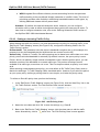
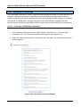
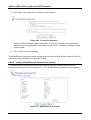
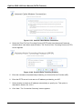
1.1
WBM Modes
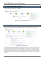
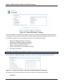
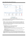
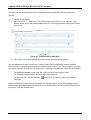
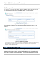
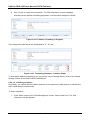
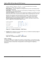
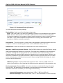
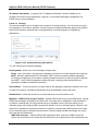
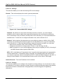
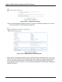
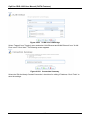
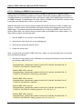
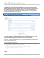
By default, OptiCon SBG-1000‘s WBM is displayed in read-only basic mode, providing you with the
ability to view your features and system parameters. This mode prevents accessing and changing
the gateway‘s settings, misconfiguration of which may harm its performance.
1
OptiCon SBG-1000 User Manual (DATA Features)
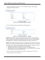
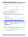
Figure 1.1 WBM – Read Only Basic Mode
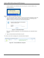
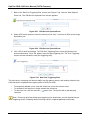
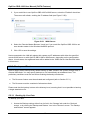
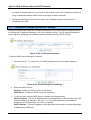
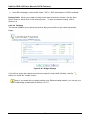
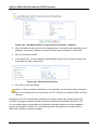
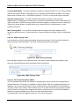
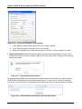
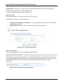
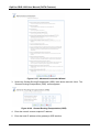
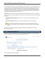
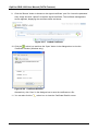
To perform configuration actions on your gateway, click the ‗Settings‘ tab. You are required to log
in.
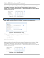
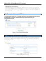
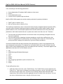
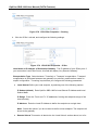
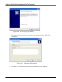
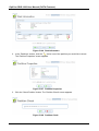
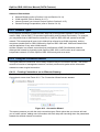
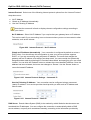
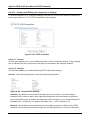
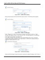
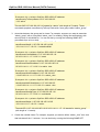
Figure 1.2 Settings Login
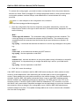
Enter your username and password, and click ‗Continue‘. The default username is ‗admin‘ and the
default password is ‗admin‘.
2
OptiCon SBG-1000 User Manual (DATA Features)
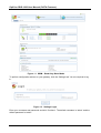
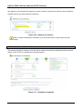
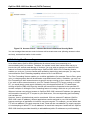
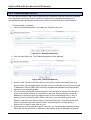
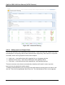
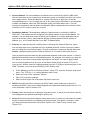
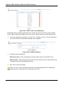
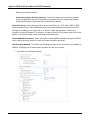
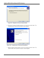
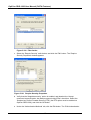
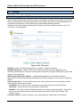
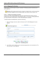
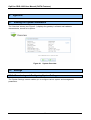
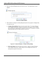
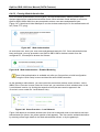
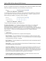
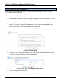
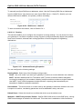
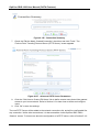
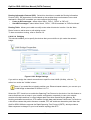
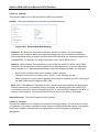
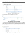
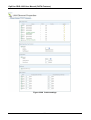
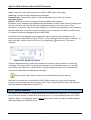
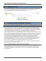
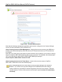
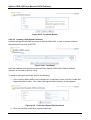
Figure 1.3 WBM – Configuration Mode
By logging in, you have switched from read-only mode to configuration mode. You can now
perform various configurations of your gateway, as described in the following sections. To return to
read-only mode, click the ‗Logout‘ link located on the top bar.
Note: Prior to changing default settings of any OptiCon SBG-1000 feature, it is
recommended that you carefully read the relevant instructions provided in this manual.
A login session will automatically time-out after an extended period of inactivity. If you try to
operate the WBM after the session has expired, the ‗Login‘ screen will appear. This feature helps
to prevent unauthorized users from accessing your session and changing the gateway‘s settings.
3
OptiCon SBG-1000 User Manual (DATA Features)
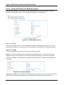
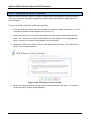
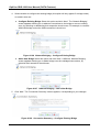
1.2
Navigational Aids
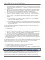
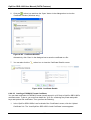
The Web-based management is a user-friendly interface, designed as a Web site that can be
explored with any Web browser. This section illustrates the WBM‘s page structure and describes
its navigational components and their hierarchical manner.
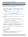
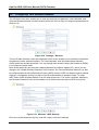
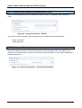
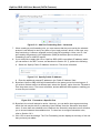
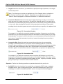
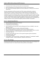
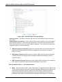
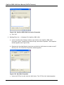
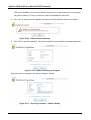
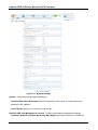
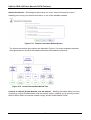
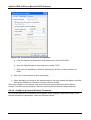
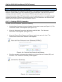
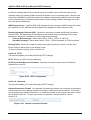
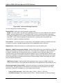
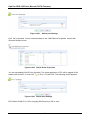
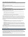
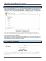
Figure 1.4 Navigation Components
1. The top level navigational aids are the Tabs, grouping the WBM screens into several main
subject areas.
Note: The following navigational components are only present in the advanced mode of
the WBM.
2. A tab may have a Menu Items bar, listing the different items relevant for the tab.
3. A menu item may have a Links Bar, located at the top-right of the screen. These links
further divide the menu item into different subjects.
4. Lastly, a page content, usually a feature‘s properties page, may have a set of Sub-tabs,
providing a division of settings in the form of yet another set of tabs.
Note: For convenience purposes, the entire WBM part of this User Manual has been
constructed in accordance with the structure of the WBM—the chapter structure is
identical to the tab structure, sections are written after item menus, etc.
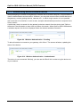
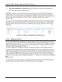
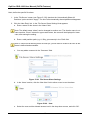
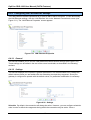
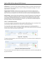
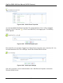
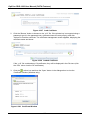
In addition, a constant links bar appears at the top of every WBM page, providing shortcuts to
information and control actions.
Figure 1.5 Constant Link Bar
The links bar includes:
• Site Map – Leads to a screen representing the hierarchial structure of the WBM.
• Reboot – Clicking this link initiates a gateway reboot.
• Logout – This link can be used to return to read-only basic mode.
4
OptiCon SBG-1000 User Manual (DATA Features)
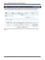
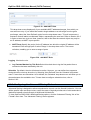
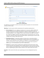
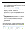
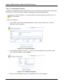
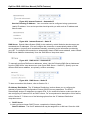
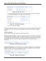
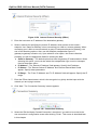
1.3
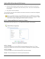
Tables in the WBM
Tables are structures used throughout the Web-based management. They handle user-defined
entries relating to elements such as network connections, local servers, restrictions and
configurable parameters. The principles outlined in this section apply to all tables in the WBM.
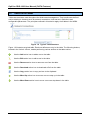
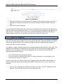
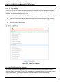
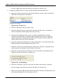
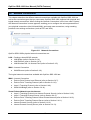
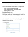
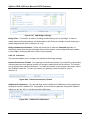
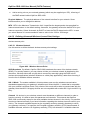
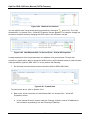
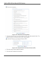
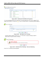
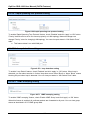
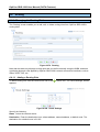
Figure 1.6 Typical Table Structure
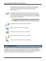
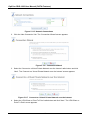
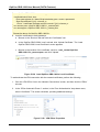
Figure 1.6 illustrates a typical table. Each row defines an entry in the table. The following buttons,
located in the ‗Action‘ column, enable performing various actions on the table entries.
Use the Add action icon to add a row to the table.
Use the Edit action icon to edit a row in the table.
Use the Remove action icon to remove a row from the table.
Use the Download action icon to download a file from the table.
Use the Copy action icon to copy an item to the clipboard.
Use the Move Up action icon to move a row one step up in the table.
Use the Move Down action icon to move a row one step down in the table.
5
OptiCon SBG-1000 User Manual (DATA Features)
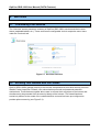
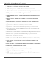
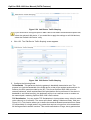
2. Home
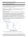
2.1
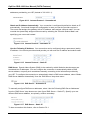
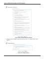
Overview Your Gateway
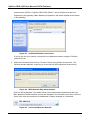
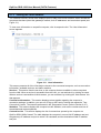
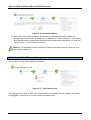
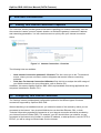
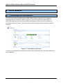
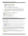
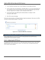
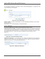
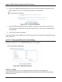
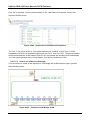
The ‗Overview‘ screen presents the status of OptiCon SBG-1000‘s various modules in one
convenient location. You can quickly and efficiently view important system details such as the
status of your Internet connection, wireless and local networks, as well as hardware peripherals.
Figure 2.1 Home – Overview
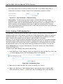
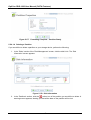
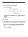
2.1.1 Viewing and Connecting to Your Broadcasted Wireless Network
The ‗Network Devices‘ section displays OptiCon SBG-1000‘s broadcasted wireless network. To
connect to this network from a wireless Windows computer, perform the following:
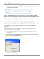
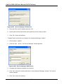
1. In the Windows system tray, click the wireless connection icon.
Figure 2.2 Wireless Icon in the System Tray
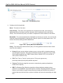
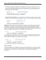
The ‗Wireless Network Connection‘ screen appears, displaying all available wireless
networks (also known as Wi-Fi hotspots) in your vicinity. If your gateway is connected and
active, you should see its wireless network displayed in this screen. The default wireless
6
OptiCon SBG-1000 User Manual (DATA Features)
network name (SSID) is ―OptiCon SBG-1000 (XXXX)‖, where XXXX are the last four
characters of the gateway‘s MAC address (as printed on the sticker located at the bottom
of the gateway).
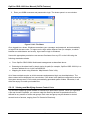
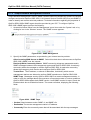
Figure 2.3 Available Wireless Connections
If you do not see your network, refresh the list of detected networks using the ‗Refresh
network list‘ link.
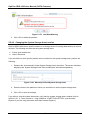
2. Select the connection and click the ‗Connect‘ button at the bottom of the screen. The
following window appears, requiring you to provide the WPA password (network key).
Figure 2.4 WPA Network Key Authentication
Enter the WPA password. The default value of this case sensitive password is same as
MAC address of WAN interface, and can be changed in the ‗Wireless‘ menu item under the
‗Home‘ tab. After the connection is established, its status changes to ‗Connected‘
Figure 2.5 Connected Wireless Network
7
OptiCon SBG-1000 User Manual (DATA Features)
A balloon appears in the notification area, announcing the successful initiation of the
wireless connection.
Figure 2.6 Wireless Connection Information
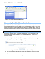
3. If you had selected the default ―Medium‖ security level during the installation wizard, any
attempt to browse the Internet will require Web authentication. The following screen
appears, requiring you to provide your username and password.
Figure 2.7 Web Authentication
Enter your username and password. You will be redirected to your requested Internet
address.
4. Open an Internet browser and browse to any site.
The ‗Home‘ screen will now display the connected wireless computer.
Figure 2.8 Connected Wireless Computer
8
OptiCon SBG-1000 User Manual (DATA Features)
2.1.2 Authenticating Wireless Network Devices
When attempting to connect to the gateway‘s network from a wireless computer, a login session is
used for authentication and connection. However, you may wish connect other wireless devices to
the gateway, such as gaming devices, cameras, etc., in which a login session in is not possible
due to the lack of an interface. In such a case, a simple authentication procedure is required in the
‗Home‘ screen.
A preliminary step is to search for the gateway‘s wireless network from the device itself. Refer to
the device‘s documentation to learn how to perform this search. When OptiCon SBG-1000 detects
a wireless request, the device is displayed under the relevant wireless connection.
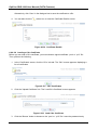
Figure 2.9 Wireless Authentication – Pending
To allow this device to connect to your gateway, click ‗Allow‘. The screen refreshes, updating the
status of the device.
Figure 2.10 Wireless Authentication – Authenticated
The device is now connected. Similarly, you can use the ‗Block‘ link in order to log the device out
of your network.
9
OptiCon SBG-1000 User Manual (DATA Features)
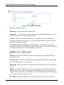
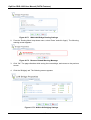
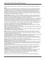
2.1.3 Viewing the Local Network
The ‗Network Devices‘ section also displays OptiCon SBG-1000‘s local network, which includes all
computers that have joined the gateway‘s network, their IP addresses, and connection speed (see
Figure 2.1).
To view more information on a specific computer, click its respective link. The ‗Host Information‘
screen appears.
Figure 2.11 Host Information
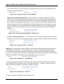
This screen presents all of the information relevant to the connected computer, such as connection
information, available services, and traffic statistics.
Services This section lists the services on the computer that are available to other computers
from the LAN. When a service is accessible from the LAN, you can activate it by clicking its name.
When a service is accessible via Web access, you can activate it by clicking the ‗Web Access‘ link
that appears.
Connection Information This section displays various details regarding the computer‘s
connection settings. In addition, you can run a Ping or ARP test by clicking the respective ‗Test
Connectivity‘ button. The tests are performed in the ‗Diagnostics‘ screen (refer to Section 6.8.7).
Statistics This section displays the computer‘s traffic statistics, such as the number and size of
transmitted and received packets.
Connection List This section displays the list of connections opened by the computer on
OptiCon SBG-1000‘s firewall. The table displays the computer‘s source LAN IP address and port,
the gateway‘s IP address and port to which it is translated, and the destination WAN IP address
and port.
10
OptiCon SBG-1000 User Manual (DATA Features)
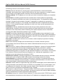
2.1.4 Viewing Attached Devices
The ‗Attached Devices‘ section displays the peripheral devices connected to your gateway. These
may include storage devices and telephones. For example, connect a storage device and refresh
the screen.
Figure 2.12 Connected Storage Device
To view more details on the connected printer, click its name link. Note that clicking the larger
printer icon redirects you to the ‗Print Server‘ screen, which also contains the list of connected
printers.
Similarly, this section displays other devices connected to the gateway. For more information on
each device type, refer to its respective section of this manual.
2.1.5 Viewing the System Status
The ‗System Status‘ section of the ‗Overview‘ screen (see Figure 2.1) displays the following
details:
•
•
The Internet connection‘s type, speed capability, and data transmission mode. Click the
‗Internet Connection‘ link for more details.
System information, which includes the gateway‘s ID, software version and uptime. Click the
‗System Information‘ headline for more details.
11
OptiCon SBG-1000 User Manual (DATA Features)
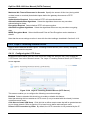
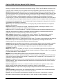
2.2
Viewing Your Network with Map View
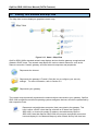
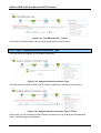
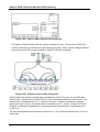
The ‗Map View‘ screen displays a graphical network map.
Figure 2.13 Home – Map View
OptiCon SBG-1000‘s standard network map displays devices that the gateway recognized and
granted a DHCP lease. The network map depicts the various network elements, such as the
Internet connection, firewall, gateway, and local network computers and peripherals.
Represents the Internet
Represents the gateway‘s Firewall. Click this icon to configure your security
settings. For more information, refer to Section 5.2.
Represents your gateway
The network map dynamically represents the network objects connected to your gateway. OptiCon
SBG-1000 recognizes commercial operating systems and game devices, which are represented by
their respective icons.
Represents a wired/wireless computer (host) connected to the gateway. This
host is either a DHCP client that has received an IP lease from OptiCon
SBG-1000, or a host with a static IP address, auto-detected by OptiCon
SBG-1000. Note that OptiCon SBG-1000 will recognize a physically connected
host and display it in the Network Map only after network activity from that host
12
OptiCon SBG-1000 User Manual (DATA Features)
has been detected (e.g. trying to browse to the WBM or to surf the Internet).
OptiCon SBG-1000 will also display incoming connections of types PPTP,
L2TP, and IPSec. Click this icon to view network information for the
corresponding host.
Represents a host whose DHCP lease has expired and not renewed. The
DHCP lease is renewed automatically, unless the host is no longer physically
connected to OptiCon SBG-1000. The disconnected host‘s icon will disappear
from the network map during the next scheduled IP lease query, performed by
OptiCon SBG-1000‘s DHCP server.
Note: This icon also represents a static IP host that has no network
activity.
Represents a wireless host connected to your gateway.
Represents a printer connected to your gateway.
Represents an IP-Phone registered to your gateway.
Represents a WiFi Phone registered to your gateway.
Represents a USB storage connected to your gateway.
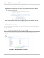
2.3
Installation Wizard
The installation wizard is the first and foremost configuration procedure, which automatically
diagnoses your network environment and configures its components. It is a step-by-step procedure
that guides you through establishing an Internet connection, a wireless network, and helps you to
subscribe for different services. The wizard progress box, located at the right hand side of the
screen, provides a monitoring tool for its steps during the installation progress.
13
OptiCon SBG-1000 User Manual (DATA Features)
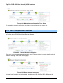
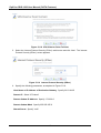
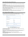
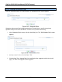
Figure 2.14 Welcome to OptiCon SBG-1000 Installation Wizard
1. To start the installation wizard, perform the following:Select the desired language and click
‗Next‘ to continue. The ‗Login Setup‘ screen appears.
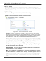
Figure 2.15 Login Setup
2. Enter a valid email address. It will be used by your service provider for sending you
important service information.
3. The ‗User Name‘ field is auto-completed by the username part of your email address. You
can enter another username, which may only consist of letters and numbers.
4. Enter a password, and retype it in the next field to verify its correctness.
Note: It is recommended to write down your login details on a piece of paper, and store it
in a safe place.
5. Click ‗Next‘. The wizard is now ready to begin your gateway‘s configuration.
14
OptiCon SBG-1000 User Manual (DATA Features)
Figure 2.16 Installation Wizard
6. Click ‗Next‘. The wizard procedure will commence, performing the steps listed in the
progress box consecutively, stopping only if a step fails or if input is required. The following
sections describe the wizard steps along with their success/failure scenarios. If a step fails,
use the ‗Retry‘ or ‗Skip‘ buttons to continue.
Warning: The installation wizard overrides all Internet connection settings, which you may
have previously defined.
2.3.1 Step 1: Test Ethernet Link
The first step is a test of the Ethernet connection.
Figure 2.17 Test Ethernet Link
This step may fail if OptiCon SBG-1000 cannot detect your Ethernet link (for example, if the cable
is unplugged). In this case, the screen changes to the following.
15
OptiCon SBG-1000 User Manual (DATA Features)
Figure 2.18 Test Ethernet Link – Failure
Verify that your Ethernet/DSL cable is connected properly, and click ‗Retry‘.
2.3.2 Step 2: Analyze Internet Connection Type
The next step is an analysis of your Internet connection.
Figure 2.19 Analyze Internet Connection Type
This step may fail if OptiCon SBG-1000 is unable to detect your Internet connection type.
Figure 2.20 Analyze Internet Connection Type – Failure
In this case, you can manually set the Internet connection type, by clicking the corresponding
button. The following screen appears.
16
OptiCon SBG-1000 User Manual (DATA Features)
Figure 2.21 Manual Internet Connection Type Setup
To learn about manually configuring your Internet connection, refer to Section 6.4.
2.3.3 Step 3: Setup Internet Connection
If your Internet connection requires login details provided by your Internet Service Provider (ISP)
(e.g. when using PPPoE), the following screen appears.
Figure 2.22 Internet Account Information
Enter your user name and password and click ‗Next‘. Failure to enter the correct details yields the
following message. Click ‗Back‘ and try again.
Figure 2.23 Setup Internet Connection
You may have forgotten your login details, issued by your ISP. OptiCon SBG-1000 saves the
17
OptiCon SBG-1000 User Manual (DATA Features)
username and password of the PPPoE connection to the ISP, even if it is restored to the factory
default settings. When restoring the connection with the installation wizard, OptiCon SBG-1000 will
offer your old login details.
Figure 2.24 Internet Account Information
2.3.4 Step 4: Test Service Provider Connection
This step tests the connectivity to your ISP.
Figure 2.25 Test Service Provider Connection
18
OptiCon SBG-1000 User Manual (DATA Features)
2.3.5 Step 5: Test Internet Connection
This step tests the connectivity to the Internet.
Figure 2.26 Test Internet Connection
2.3.6 Step 6: Wireless Setup
This step enables you to rename your wireless network, as well as change its security level.
Figure 2.27 Wireless Setup
OptiCon SBG-1000 assigns a default name for its wireless network, which you may later change.
Select the wireless security level. The default ―Medium‖ level secures your network by requiring
users to provide a password in order to connect. ―High‖ level utilizes the Wi-Fi Protected Access
(WPA) protocol, requiring a password (network key) as well, but also encrypts the wireless traffic.
When selecting this option, enter an eight-character password in the provided field. Click ‗Next‘ to
continue.
19
OptiCon SBG-1000 User Manual (DATA Features)
2.3.6.1 Setup via Wireless Connection
If you are running the installation wizard while being connected to OptiCon SBG-1000 via a
wireless connection, the wizard does not change the default SSID (to prevent you from
disconnecting). If you choose to change it manually, the following screen appears, requesting that
you re-establish your wireless connection (from your computer) before proceeding with the wizard.
Figure 2.28 Wireless Setup
This screen also appears after selecting the High wireless security level, or after changing the
previously entered WPA password (see Figure 2.27).
2.3.6.2 Additional SSIDs with Virtual Access Points
If your gateway supports multiple virtual access points, an additional pre-configured WPA-secured
wireless network is displayed in ‗Wireless Setup‘ screen.
Figure 2.29 Wireless Setup
You can change the default name and network key (password) of this encrypted wireless network
in their respective text fields (clicking ‗Next‘ will save the new details). This wireless network will
20
OptiCon SBG-1000 User Manual (DATA Features)
also appear in the ‗Network Connections‘ screen under the ‗System‘ tab, where it can be edited or
deleted such as any other network connection.
Figure 2.30 Network Connections
Note: In order to delete this connection, you must first remove it from under the LAN
bridge.
2.3.7 Step 7: Installation Completed
This screen provides a summary of all the above Internet connection configuration steps and their
results. Click ‗Finish‘ to complete the wizard procedure.
Figure 2.31 Installation Completed
21
OptiCon SBG-1000 User Manual (DATA Features)
2.4
Configuring Your Wireless Network
The ‗Wireless‘ menu item enables you to view and configure the gateway‘s ‗Home Network‘ and
‗Secured Wireless Network‘ wireless access points (the rest can only be configured as described in
Section 4.3).
Figure 2.32 Settings – Wireless
The first ‗Enable Wireless‘ check box displayed in this screen enables you to activate or deactivate
the gateway‘s entire wireless interface. The ‗Home Network‘ and ‗Secured Wireless Network‘
access points are activate by default. You can change their network names (also known as SSIDs)
in the respective name fields.
Both access points are secured with a default password (by default ―wlpass123‖), which you can
change in the ‗Global Wireless Password‘ field. However, the ‗Secured Wireless Network‘ can also
be configured with the Wired Equivalent Privacy (WEP) protocol. WEP is a data encryption method
utilizing a 13-character security key that is used for authentication of wireless clients. To utilize
WEP, select ‗WEP Wireless Network‘ from the drop-down menu. The screen refreshes, displaying
the ‗Wireless Password‘ field, which enables you to define the access point‘s WEP security key.
Figure 2.33 Wireless – WEP Security
Enter your personalized security key, and click ‗Apply‘ to save the settings.
22
OptiCon SBG-1000 User Manual (DATA Features)
3. Internet Connection
3.1
Viewing Your Internet Connection Properties
The ‗Overview‘ screen provides general information regarding your Internet connection, such as
the connection‘s status, protocol, speed, duration, as well as the gateway‘s external IP address
and networking parameters. You can use this screen to quickly view your Internet connection
status.
Figure 3.1 Internet Connection – Overview
The following links are available:
•
Have Internet Connection problems? Click here This link routes you to the ‗Troubleshoot‘
screen, where you can run tests in order to diagnose and resolve Internet connectivity
problems.
• Click Here For Internet Connection Utilization Click this link to analyze the traffic usage of
your WAN connection (for more information, refer to Section 5.3).
In addition, this screen displays OptiCon SBG-1000‘s top bandwidth consuming applications and
computers, described in Section 5.3.2.
3.2
Configuring Your Internet Connection
The ‗Settings‘ screen provides basic configuration options for the different types of Internet
connections supported by OptiCon SBG-1000.
When subscribing to a broadband service, you should be aware of the method by which you are
connected to the Internet. Your physical WAN device can be either Ethernet, DSL, or both.
Technical information regarding the properties of your Internet connection should be provided by
your Internet Service Provider (ISP). For example, your ISP should inform you whether you are
connected to the Internet using a static or dynamic IP address, or what protocols, such as PPTP or
PPPoE, you will be using to communicate over the Internet.
23
OptiCon SBG-1000 User Manual (DATA Features)
Figure 3.2 Internet Connection – Settings
If you are already connected to the Internet, this screen provides information on your connection.
The drop-down menu provides the WAN connection types supported by OptiCon SBG-1000, and
your WAN connection can be configured using one of the following methods.
•
•
•
•
•
•
Manual IP Address Ethernet Connection
Automatic IP Address Ethernet Connection
Point-to-Point Tunneling Protocol (PPTP)
Layer 2 Tunneling Protocol (L2TP)
Point-to-point protocol over Ethernet (PPPoE)
No Internet connection
3.2.1 Manual IP Address Ethernet Connection
Select ‗Manual IP Address Ethernet Connection‘ from the ‗Connection Type‘ drop-down menu.
Figure 3.3 Internet Connection – Manual IP Address Ethernet Connection
According to your service provider‘s instructions, specify the following parameters:
• IP address
24
OptiCon SBG-1000 User Manual (DATA Features)
• Subnet mask
• Default gateway
• Primary DNS server
• Secondary DNS server
3.2.2 Automatic IP Address Ethernet Connection
Select ‗Automatic IP Address Ethernet Connection‘ from the ‗Connection Type‘ drop-down menu.
OptiCon SBG-1000 will obtain the WAN IP and DNS IP addresses from a DHCP server on the
WAN.
Figure 3.4 Internet Connection – Automatic IP Address Ethernet Connection
3.2.3 Point-to-Point Tunneling Protocol (PPTP)
Select ‗Point-to-Point Tunneling Protocol (PPTP)‘ from the ‗Connection Type‘ drop-down menu.
Figure 3.5 Internet Connection – PPTP
Configure the following parameters according to your ISP information:
• PPTP Server Host Name or IP Address
• Login User Name
• Login Password
Select the Internet Protocol:
25
OptiCon SBG-1000 User Manual (DATA Features)
Most Internet Service Providers (ISPs) provide dynamic IP addresses, hence the default ―Obtain
an IP Address Automatically‖. Should this not be the case, select the ―Use the Following IP
Address‖ option. The screen refreshes. Enter the IP Address, Subnet Mask, and Default Gateway
provided to you by your ISP.
Figure 3.6 PPTP – Static IP Address
3.2.4 Layer 2 Tunneling Protocol (L2TP)
Select ‗Layer 2 Tunneling Protocol (L2TP)‘ from the ‗Connection Type‘ drop-down menu.
Figure 3.7 Internet Connection – L2TP
Configure the following parameters according to your ISP information:
•
• L2TP Server Host Name or IP Address
• Login User Name
• Login Password
Select the Internet Protocol:
Most Internet Service Providers (ISPs) provide dynamic IP addresses, hence the default ―Obtain
an IP Address Automatically‖. Should this not be the case, select the ―Use the Following IP
Address‖ option. The screen refreshes. Enter the IP Address, Subnet Mask, and Default Gateway
provided to you by your ISP.
Figure 3.8 L2TP – Static IP Address
26
OptiCon SBG-1000 User Manual (DATA Features)
3.2.5 Point-to-Point Protocol over Ethernet (PPPoE)
Select ‗Point-to-point protocol over Ethernet (PPPoE)‘ from the ‗Connection Type‘ drop-down
menu.
Figure 3.9 Internet Connection – PPPoE
Your Internet Service Provider (ISP) should provide you with the following information:
• Login user name
• Login password
3.2.6 No Internet Connection
Select ‗No Internet Connection‘ from the ‗Connection Type‘ drop-down menu (see Figure 3.10).
Choose this connection type if you do not have an Internet connection, or if you want to disable all
existing connections.
Figure 3.10 Internet Connection – No Internet Connection
27
OptiCon SBG-1000 User Manual (DATA Features)
4. Local Network
4.1
Overviewing Your Local Network
The ‗Overview‘ screen presents OptiCon SBG-1000‘s network summary. This includes all
connected devices: computers, disks, and phones. When this screen is loaded, OptiCon
SBG-1000 begins the process of automatically detecting the network services available on
connected computers (hosts). The screen then refreshes, displaying each computer‘s network
services.
Figure 4.1 Local Network Overview
To view more information on a specific computer, click its respective link. The ‗Host Information‘
screen appears.
28
OptiCon SBG-1000 User Manual (DATA Features)
Figure 4.2 Host Information
This screen presents all information that is relevant to the connected computer, such as
connection settings, available services, traffic statistics, and connection list. It also enables you to
perform connectivity tests with the computer.
Services This section lists the services enabled on the computer that are available to other
computers in the LAN, via Web access, or from both. When a service is accessible from the
LAN, you can activate it by either clicking its name or the URL that appears (see Figure 4.2).
When a service is accessible via Web access, you can activate it by clicking the ‗Web Access‘
link that appears. Available services are:
1
Shared Files Access the computer‘s shared files directory.
HTTP Access the computer‘s HTTP server (if available).
FTP Open an FTP session with the computer.
Add Access Control Rule Block access to Internet services from the computer, or allow
access if the firewall is set to a ―High‖ security level (for more information, refer to
Section 5.2.2).
• Add Port Forwarding Rule Expose services on the computer to external Internet users
(for more information, refer to Section 5.2.3).
Connection Information This section displays various details regarding the computer‘s
connection settings. In addition, you can run a Ping or ARP test by clicking the respective ‗Test
Connectivity‘ button. The tests are performed in the ‗Diagnostics‘ screen (refer to Section 6.8.7).
Statistics This section displays the computer‘s traffic statistics, such as the number and size of
•
•
•
29
OptiCon SBG-1000 User Manual (DATA Features)
transmitted and received packets.
Connection List This section displays the list of connections opened by the computer on
OptiCon SBG-1000‘s firewall. The table displays the computer‘s source LAN IP address and
port, the gateway‘s IP address and port to which it is translated, and the destination WAN IP
address and port.
4.2
Viewing the Gateway’s LAN Devices
The ‗Device‘ screen (see Figure 4.3) presents a summary of OptiCon SBG-1000‘s LAN devices,
including bridge (if one exists), Ethernet and wireless, and the status of each one
(connected/disconnected).
Figure 4.3 Local Network Device View
4.3
Configuring Your Wireless Connection
The ‗Wireless‘ menu item concentrates the wireless LAN settings of your gateway. This screen
presents OptiCon SBG-1000‘s wireless connection settings, and enables you to change them
according to your needs.
Figure 4.4 Wireless Overview
30
OptiCon SBG-1000 User Manual (DATA Features)
Enable Wireless Select or deselect this check box to enable or disable the wireless interface.
Channel All devices in your wireless network broadcast on different channels. Leaving this
parameter on Automatic ensures that OptiCon SBG-1000 continuously scans for the most
available wireless channel in your area. It is possible to select a channel manually if you have
information regarding the wireless channels used in your vicinity. The channels available
depend on the regulatory authority (stated in brackets) to which your gateway conforms. For
example, the European regulatory authority (ETSI) has allocated 13 available channels, while
the US regulatory authority (FCC) has allocated 11 available channels.
Network Name (SSID) The SSID is the network name shared among all points in a wireless
network. It is case-sensitive and must not exceed 32 characters. Note that you may use ASCII
characters only. For added security, you may change the default SSID to a unique name.
Type This field shows your wireless security settings.
Unsecured - This option disables security on your wireless connection. Any wireless
computer in your area will be able to connect to the Internet using your connection‘s
bandwidth.
WPA - A data encryption method for 802.11 wireless LANs.
WPA2 - An enhanced version of WPA, and defines the 802.11i protocol.
WPA and WPA2 - A mixed data encryption method, which utilizes both WPA and WPA2.
WEP - A data encryption method utilizing a statically defined key as the wireless
password. Note that the static key must be defined in the wireless Windows client as well.
Web Authentication - With this option, wireless clients attempting to connect to the
wireless connection will receive OptiCon SBG-1000‘s main login screen. By logging into the
WBM, clients authenticate themselves and are then able to use the connection.
Wireless Password The wireless password required to connect to the gateway‘s wireless
network. You may change the default password in the ‗Network Connections‘ menu item under
the ‗System‘ tab. This password must be at least an 8 characters long.
4.4
Managing Your Shared Printers
OptiCon SBG-1000 includes a print server that enables your LAN users to share printers attached
to the gateway via the USB connection. This eliminates the need to physically connect your printer
to a dedicated host, which should be shared and always left on. In addition, the print server offers
you such advantages as:
•
Support for several print protocols, which enable you to connect Windows, Unix and Mac
hosts to the network printer.
•
Ability to define printer access permissions for specific LAN users.
31
OptiCon SBG-1000 User Manual (DATA Features)
4.4.1 Configuring the Print Server
Access the print server settings by clicking the ‗Shared Printers‘ menu item under the ‗Local
Network‘ tab. The ‗Print Server‘ screen appears, enabling you to manage your network printer.
Figure 4.5 Print Server
Enabled Select or deselect this check box to enable or disable this feature.
Spool to Disk Select this check box to temporarily store your print jobs on the disk share, until
they are finished. This is especially useful if you would like the printer to process the print job even
after you turn the computer off.
The ‗Printers‘ section of this screen displays the printer(s) connected to OptiCon SBG-1000, the
device status, and print job information. Click a printer‘s name link to view its details. The ‗Printer‘
screen appears.
Figure 4.6 Connected Printer
32
OptiCon SBG-1000 User Manual (DATA Features)
4.5
Managing Your Private Telephony Switching System
OptiCon SBG-1000 provide customers state-of the art of Aria Technologies Africa‘s Internet
Protocol Private Branch Exchange (IP-PBX) features, using the menu in the ‗Services‘ Tab.
Figure 4.7 IP-PBX Lines
For more information about the IP-PBX features, refer to ‗OptiCon SBG-1000 IP-PBX Features
Manual‘.
33
OptiCon SBG-1000 User Manual (DATA Features)
5. Services
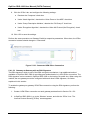
5.1
Overviewing Your Services
The ‗Overview‘ screen presents a summary of OptiCon SBG-1000‘s services and their current
status (enabled/disabled, etc.). These services are configurable via their respective menu items
under the ‗Services‘ tab.
Figure 5.1 Services Overview
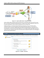
5.2
Securing Your Network with the Firewall
OptiCon SBG-1000‘s gateway security suite includes comprehensive and robust security services:
Stateful Packet Inspection Firewall, user authentication protocols and password protection
mechanisms. These features together allow users to connect their computers to the Internet and
simultaneously be protected from the security threats of the Internet. The firewall has been
exclusively tailored to the needs of the residential/office user and has been pre-configured to
provide optimum security (see Figure 5.2).
34
OptiCon SBG-1000 User Manual (DATA Features)
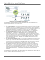
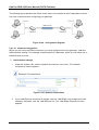
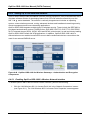
Figure 5.2 OptiCon SBG-1000’s Firewall in Action
OptiCon SBG-1000‘s firewall provides both the security and flexibility that home and office users
seek. It provides a managed, professional level of network security while enabling the safe use of
interactive applications, such as Internet gaming and video-conferencing.
Additional features, including browsing restrictions and access control, can also be easily
configured locally by the user through a user-friendly Web-based interface, or remotely by a
service provider. The OptiCon SBG-1000 firewall supports advanced filtering, designed to allow
comprehensive control over the firewall‘s behavior. You can define specific input and output rules,
control the order of logically similar sets of rules and make a distinction between rules that apply to
WAN and LAN network devices.
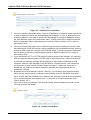
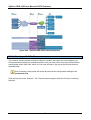
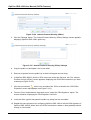
5.2.1 Configuring Basic Security Settings
The firewall‘s ‗Overview‘ screen enables you to configure the gateway‘s basic security settings.
Figure 5.3 Firewall – Overview
35
OptiCon SBG-1000 User Manual (DATA Features)
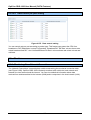
You may choose between three pre-defined security levels for OptiCon SBG-1000: Minimum,
Typical (the default), and Maximum. The following table summarizes OptiCon SBG-1000‘s
behavior for each of the three security levels.
Security Level
Requests Originating in the
WAN (Incoming Traffic)
Requests Originating in the
LAN (Outgoing Traffic)
Maximum Security
Blocked: No access to home
network from Internet, except as
configured in the Port Forwarding,
DMZ host and Remote Access
screens
Limited: Only commonly-used
services, such as
Web-browsing and e-mail, are
permitted. The list of allowed
services can be edited in the
Access Control screen (refer
to Section 5.2.2)
Typical Security (Default)
Blocked: No access to home
network from Internet, except as
configured in the Port Forwarding,
DMZ host and Remote Access
screens
Unrestricted: All services are
permitted, except as
configured in the Access
Control screen
Minimum Security
Unrestricted: Permits full access Unrestricted: All services are
from Internet to home network; all permitted, except as
connection attempts permitted
configured in the Access
Control screen
Table 5.1 OptiCon SBG-1000’s Firewall Security Levels
To configure OptiCon SBG-1000‘s basic security settings, perform the following:
1. Choose between the three predefined security levels described in the table above.
Note: Using the Minimum Security setting may expose the home network to
significant security risks, and thus should only be used, when necessary, for short
periods of time.
2. Check the 'Block IP Fragments' box in order to protect your home network from a common
type of hacker attack that could make use of fragmented data packets to sabotage your
home network. Note that VPN over IPSec and some UDP-based services make legitimate
use of IP fragments. In case of enabling these services, you will need to allow IP fragments
to pass into the home network.
3. Click 'OK' to save the settings.
By default, the selected security level affects access to such Internet services as Telnet, FTP,
HTTP, HTTPS, DNS, IMAP, POP3 and SNTP. Note that some programs (such as some Internet
messengers and Peer-To-Peer clients) tend to use ports of the above-mentioned services in case
they cannot connect using their own default ports. When allowing this behavior, the Internet
connection requests of such programs will not be blocked, even at the ‗Maximum‘ security level.
After the security level is set, the firewall regulates the flow of data between the home network and
the Internet. Both incoming and outgoing data are inspected and then either accepted (allowed to
pass through OptiCon SBG-1000) or rejected (barred from passing through OptiCon SBG-1000),
according to a flexible and configurable set of rules. These rules are designed to prevent unwanted
36
OptiCon SBG-1000 User Manual (DATA Features)
intrusions from the outside, while allowing home users access to the Internet services that they
require.
The firewall rules specify what types of services available on the Internet may be accessed from
the home network and what types of services available in the home network may be accessed
from the Internet. Each request for a service that the firewall receives, whether originating from the
Internet or from a computer in the home network, is checked against the set of firewall rules to
determine whether the request should be allowed to pass through the firewall. If the request is
permitted to pass, then all subsequent data associated with this request (a ―session‖) will also be
allowed to pass, regardless of its direction.
For example, when you point your browser to a Web page, a request is sent to the Internet for
retrieving and loading this page. When this request reaches OptiCon SBG-1000, its firewall
identifies the request‘s type and origin. In the Web browsing example, HTTP is the request‘s type,
and your PC is its origin. Unless you have configured OptiCon SBG-1000‘s Access Control feature
to block requests of this type originating from your PC, the firewall will allow this request to pass
out onto the Internet (for more on configuring OptiCon SBG-1000‘s Access Control, refer to
Section 5.2.2).
When the Web page is returned from the Web server, the firewall associates it with the current
connection and allows it to pass, regardless of whether HTTP access from the Internet to your
home network is blocked or permitted. It is the origin of the request, not the subsequent responses
to this request, that determines whether a connection can be established or not.
5.2.2 Controlling Your Network’s Access to Internet Services
You may want to block specific computers within the home network (or even the whole network)
from accessing certain services available on the Internet. For example, you may want to prohibit
one computer from browsing the Web, another computer from transferring files using FTP, and the
whole network from accessing email (by blocking the outgoing requests to POP3 servers on the
Internet). The ‗Access Control‘ screen enables you to apply restrictions on the types of connection
requests that may pass from the home network out to the Internet, and to block the corresponding
network traffic in both directions. In addition, this screen can be used for allowing access to
specific services when the ‗Maximum‘ security is applied (as described in Section 5.2.1).
To block access to a service available on the Internet:
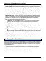
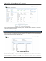
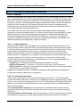
1. Click the ‗Access Control‘ link under the ‗Firewall‘ menu item. The ‗Access Control‘ screen
appears.
Figure 5.4 Access Control
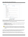
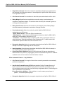
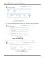
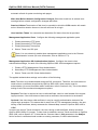
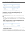
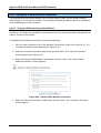
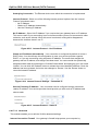
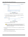
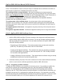
2. Click the ‗New Entry‘ link. The ‗Add Access Control Rule‘ screen appears.
37
OptiCon SBG-1000 User Manual (DATA Features)
Figure 5.5 Add Access Control Rule
3. From the ‗Address‘ drop-down menu, select an IP address or a computer name from the list
in order to apply the rule on the corresponding LAN computer, or ‗Any‘ to apply the rule on
all LAN computers. If you wish to add a new LAN address or a range of addresses, select
the ‗User Defined‘ option in the drop-down menu. This will commence a sequence that will
add a new Network Object, representing the new host. Refer to Section 6.9.2 in order to
learn how to do so.
4. From the ‗Protocol‘ drop-down menu, select the type of protocol used by the service. Note
that selecting the ‗Show All Services‘ option expands the list of available protocols. Select a
protocol or add a new one using the ‗User Defined‘ option. This will commence a sequence
that will add a new Service, representing the protocol. Refer to Section 6.9.2 in order to
learn how to do so.
5. If you selected the HTTP or HTTPS protocol (to deny access to the Internet), you may also
wish to enable the feature ‗Reply an HTML page to the blocked client‘. When its check box
is selected, the following message will be displayed in the browser of the blocked LAN
computer, when the user attempts to surf the Internet: ―Access Denied – this computer is
not allowed to surf the Internet. Please contact your admin.‖. When this check box is
deselected, the computer‘s Internet connection requests are simply ignored and no
notification is issued.
6. By default, the rule will always be active. However, you can define time segments during
which the rule may be active, by selecting ‗User Defined‘ from the ‗Schedule‘ drop-down
menu. If more than one scheduler rule is defined, the ‗Schedule‘ drop-down menu will allow
you to choose between the available rules. To learn how to configure scheduler rules,
refer to Section 6.9.3.
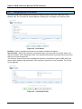
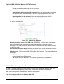
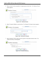
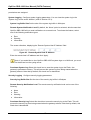
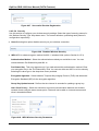
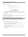
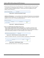
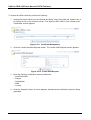
7. Click ‗OK‘ to save your changes. The ‗Access Control‘ screen displays a summary of the
rule that you have just added.
Figure 5.6 Access Control Rule
38
OptiCon SBG-1000 User Manual (DATA Features)
You may edit the access control rule by modifying its entry displayed under the 'Local Host'
column.
To modify a rule‘s entry:
1. Click the rule‘s
action icon. The ‗Edit Access Control Rule‘ screen appears. This
screen allows you to edit all the parameters that you configured when creating the access
control rule.
Figure 5.7 Edit Access Control Rule
2. Click ‗OK‘ to save your changes and return to the ‗Access Control‘ screen.
You can disable an access control rule in order to make the corresponding service available,
without having to remove the rule from the ‗Access Control‘ screen. This may be useful if you wish
to unblock access to the service only temporarily, intending to reinstate the restriction in the future.
•
•
•
To temporarily disable a rule, clear the check box next to the service name.
To reinstate it at a later time, simply reselect the check box.
To remove a rule, click the service‘s
action icon. The service will be permanently
removed.
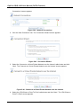
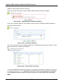
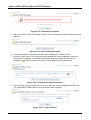
When the ‗Maximum‘ security level is applied, the ‗Access Control‘ screen also displays a list of
automatically generated firewall rules that allow access to specific Internet services from the LAN
computers, over pre-defined ports.
39
OptiCon SBG-1000 User Manual (DATA Features)
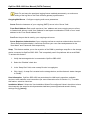
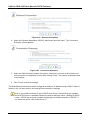
Figure 5.8 Access Control – Allowed Services in Maximum Security Mode
You can manage these access control rules as well as create new ones (allowing access to other
services), as described earlier in this section.
5.2.3 Using Port Forwarding
In its default state, OptiCon SBG-1000 blocks all external users from connecting to or
communicating with your network. Therefore, the system is safe from hackers who may try to
intrude into your network and damage it. However, you may wish to expose your network to the
Internet in certain limited and controlled ways. OptiCon SBG-1000‘s Port Forwarding feature
enables you to do so. If you are familiar with networking terminology and concepts, you may have
encountered the Port Forwarding capability referred to as ―Local Servers‖.
The ‗Port Forwarding‘ feature enables you to define applications (for example, Peer-to-Peer, game,
voice, or chat programs) that will be allowed a controlled Internet activity. In addition, you may use
Port Forwarding to allow external access to specific servers running on your network. For example,
if you wish to allow external access to your File Transfer Protocol (FTP) server running on a LAN
PC, you would simply create a port forwarding rule, which specifies that all FTP-related data
arriving at OptiCon SBG-1000 from the Internet will henceforth be forwarded to the specified PC.
Another example of utilizing the Port Forwarding feature is hosting a Web site on your own server.
When an Internet user points a browser to OptiCon SBG-1000‘s external IP address, the gateway
will forward the incoming HTTP request to your Web server, if the corresponding port forwarding
rule had been set.
However, there is a limitation that must be considered. With one external IP address (OptiCon
SBG-1000‘s main IP address), different applications can be assigned to your LAN computers,
however each type of application is limited to use one computer. For example, you can define that
FTP will use address X to reach computer A and Telnet will also use address X to reach computer
A, but attempting to define FTP to use address X to reach both computer A and B will fail. OptiCon
SBG-1000 therefore provides the ability to add additional public IP addresses to port forwarding
40
OptiCon SBG-1000 User Manual (DATA Features)
rules, which you must first obtain from your ISP, and enter into the ‗NAT IP Addresses Pool‘ (refer
to Section 5.2.7). You will then be able to define FTP to use address X to reach computer A, and
address Y to reach computer B.
Additionally, OptiCon SBG-1000‘s Port Forwarding feature enables you to redirect traffic to a
different port instead of the one for which it was designated. For example, if you have a Web
server running on your PC on port 8080, you may wish to redirect anyone who browses to OptiCon
SBG-1000‘s external IP address (by default, over port 80) to your Web server.
Note: A remote administration service will have precedence over the port forwarding
rule created for a local server, when both are configured to utilize the same port. For
example, when both the Web server (running on your LAN host) and a remote
administration service (utilized by the ISP) are configured to use port 80, OptiCon
SBG-1000 will grant access to the remote administration traffic. The traffic destined
for your Web server will be blocked until you disable the remote administration
service or change its dedicated port. For more information about the remote
administration services, refer to Section 6.7.3.
Some applications that work with such protocols as FTP, TFTP, PPTP and H.323, require the
support of specific Application Level Gateway (ALG) modules in order to work inside the home
network. Data packets associated with these applications contain information that allows them to
be routed correctly. An ALG is needed to handle these packets and ensure that they reach their
intended destinations. OptiCon SBG-1000 is configured with a robust list of ALG rules in order to
enable maximum functionality in the home network. These ALG rules are automatically applied
based on the destination ports. You may also create additional ALG rules. To learn how to do so,
refer to Section 5.2.8.2).
5.2.3.1 Adding a Port Forwarding Rule
To allow remote access to a service running one a LAN computer, create a corresponding port
forwarding rule as follows:
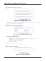
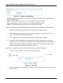
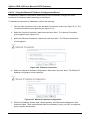
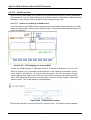
1. Click ‗Port Forwarding‘ under the ‗Firewall‘ menu item. The ‗Port Forwarding‘ screen
appears.
Figure 5.9 Port Forwarding
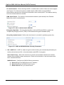
2.
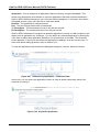
Click the ‗New Entry‘ link. The ‗Add Port Forwarding Rule‘ screen appears.
41
OptiCon SBG-1000 User Manual (DATA Features)
Figure 5.10 Add Port Forwarding Rule – Basic
3.
Click the ‗Advanced‘ button at the bottom of the screen. The screen expands.
Figure 5.11 Add Port Forwarding Rule – Advanced
4. The ‗Local Host‘ drop-down menu lists your available LAN computers. Select a computer
that provides the service, to which you wish to grant access over the Internet. If you would
like to add a new computer, select the ‗User Defined‘ option in the drop-down menu. This
will commence a sequence that will add a new Network Object, representing the new host.
Refer to Section 6.9.2 in order to learn how to do so. Note that unless an additional external
IP address has been added, only one LAN computer can be assigned to provide a specific
service or application.
5. From the ‗Protocol‘ drop-down menu, select the type of protocol used by the service. Note
that selecting the ‗Show All Services‘ option expands the list of available protocols. Select a
protocol or add a new one using the ‗User Defined‘ option. This will commence a sequence
that will add a new Service, representing the protocol. Refer to Section 6.9.2 in order to
learn how to do so.
6. Click the ‗Advanced‘ button at the bottom of the screen. The screen refreshes, displaying
the ‗Forward to Port‘ and ‗Schedule‘ drop-down menus.
42
OptiCon SBG-1000 User Manual (DATA Features)
Figure 5.12 Add Port Forwarding Rule – Advanced
7. When creating a port forwarding rule, you must ensure that the port used by the selected
protocol is not already in use by any other of your local services, which, in this case, may
stop functioning. A common example is when using SIP signaling in Voice over IP—the
port used by the gateway‘s VoIP application (5060) is the same port on which port
forwarding is set for LAN SIP agents.
8. If you would like to apply this rule on OptiCon SBG-1000‘s non-default IP address (which
you can define in the ‗NAT‘ screen, as described in Section 5.2.7), perform the following:
a. Select the ‗Specify Public IP Address‘ check box. The screen refreshes.
Figure 5.13 Specify Public IP Address
b. Enter the additional external IP address in the ‗Public IP Address‘ field.
9. By default, OptiCon SBG-1000 will forward traffic to the same port as its incoming port. If
you wish to redirect traffic to a different port, select the ‗Specify‘ option from the ‗Forward to
Port‘ drop-down menu. The screen refreshes, and an additional field appears, enabling you
to enter the port number.
Figure 5.14 Forward to a Specific Port
10. By default, the rule will always be active. However, you can define time segments during
which the rule may be active, by selecting ‗User Defined‘ from the ‗Schedule‘ drop-down
menu. If more than one scheduler rule is defined, the ‗Schedule‘ drop-down menu will allow
you to choose between the available rules. To learn how to configure scheduler rules,
refer to Section 6.9.3.
11. Click ‗OK‘ to save the settings. The ‗Port Forwarding‘ screen displays a summary of the rule
that you have just added.
43
OptiCon SBG-1000 User Manual (DATA Features)
Figure 5.15 Port Forwarding Rule
You may edit the port forwarding rule by clicking its entry under the ‗Local Host‘ column in the ‗Port
Forwarding‘ screen. You can also disable the rule in order to make a service unavailable without
having to remove the rule from the ‗Port Forwarding‘ screen. This may be useful if you wish to
make the service unavailable only temporarily, intending to reinstate it in the future.
•
•
•
To temporarily disable a rule, clear the check box next to the service name.
To reinstate it at a later time, simply reselect the check box.
To remove a rule, click the service‘s
action icon. The service will be permanently
removed.
5.2.4 Designating a DMZ Host
The DMZ (Demilitarized) Host feature enables you to expose one local computer to the Internet.
Designate a DMZ host when:You wish to use a special-purpose Internet service, such as an
on-line game or video-conferencing program, that is not present in the Port Forwarding list, and for
which no port range information is available. You are not concerned with security, and wish to
expose one computer to all services without restriction.
Warning: A DMZ host is not protected by the firewall and may be vulnerable to attack.
Designating a DMZ host may also put other computers in the home network at risk. When
designating a DMZ host, you must consider the security implications, and protect it if
necessary
An incoming request for accessing a service in the home network, such as a Web server, is fielded
by OptiCon SBG-1000. OptiCon SBG-1000 will forward this request to the DMZ host if one is
designated, unless the service is being provided by another LAN PC (defined in a Port Forwarding
rule), in which case that PC will receive the request instead. To designate a local computer as a
DMZ Host:
1. Click ‗DMZ Host‘ under the ‗Firewall‘ menu. The ‗DMZ Host‘ screen appears.
44
OptiCon SBG-1000 User Manual (DATA Features)
Figure 5.16 DMZ Host
2. Select the check box, and enter the local IP address of the computer that you would like to
designate as a DMZ host. Note that only one LAN computer may be a DMZ host at any
time.
3. Click ‗OK‘ to save the settings.
You can disable the DMZ host so that it will not be fully exposed to the Internet, but will keep its IP
address recorded in the ‗DMZ Host‘ screen. To do so, clear the check box next to the DMZ IP field,
and click ‗OK‘. This may be useful if you wish to temporarily disable the DMZ host, intending to
enable it again in the future. To reinstate it at a later time, reselect the check box.
5.2.5 Using Port Triggering
Port triggering is used for setting a dynamic port forwarding configuration. By setting port triggering
rules, you can allow inbound traffic to arrive at a specific LAN host, using ports different than those
used for the outbound traffic. This is called port triggering since the outbound traffic triggers to
which ports inbound traffic is directed.
For example, consider a gaming server that is accessed using the UDP protocol on port 2222. The
gaming server responds by connecting the user using UDP on port 3333, when starting gaming
sessions. In such a case you must use port triggering, since this scenario conflicts with the
following default firewall settings:
•
•
The firewall blocks inbound traffic by default.
The server replies to OptiCon SBG-1000‘s IP, and the connection is not sent back to your
host, since it is not part of a session.
In order to solve this, you need to define a Port Triggering entry, which allows inbound traffic on
UDP port 3333 only after a LAN host generated traffic to UDP port 2222. To do so, perform the
following:
1. Click the ‗Port Triggering‘ link under the ‗Firewall‘ menu item. The ‗Port Triggering‘ screen
appears. This screen will list all of the port triggering entries.
45
OptiCon SBG-1000 User Manual (DATA Features)
Figure 5.17 Port Triggering
2. Select the ‗User Defined‘ option to add an entry. The ‗Edit Port Triggering Rule‘ screen
appears.
Figure 5.18 Edit Port Triggering Rule
3. Enter a name for the service (e.g. ―game_server‖), and click the ‗New Trigger Ports‘ link.
The ‗Edit Service Server Ports‘ screen appears.
Figure 5.19 Edit Service Server Ports
4. From the ‗Protocol‘ drop-down menu, select ‗UDP‘. The screen will refresh, providing
source and destination port options (see Figure 5.20).
5. Leave the ‗Source Ports‘ drop-down menu at its default ―Any‖. From the ‗Destination Ports‘
drop-down menu, select ―Single‖. The screen will refresh again, providing an additional field
in which you should enter ―2222‖ as the destination port.
Figure 5.20 Edit Service Server Ports
6. Click ‗OK‘ to save the settings.
46
OptiCon SBG-1000 User Manual (DATA Features)
7. Back in the ‗Edit Port Triggering Rule‘ screen (see Figure 5.18), click the ‗New Opened
Ports‘ link. The ‗Edit Service Opened Ports‘ screen appears.
Figure 5.21 Edit Service Opened Ports
8. Select UDP as the protocol, leave the source port at ―Any‖, and enter a 3333 as the single
destination port.
Figure 5.22 Edit Service Opened Ports
9. Click ‗OK‘ to save the settings. The ‗Edit Port Triggering Rule‘ screen will present your
entered information. Click ‗OK‘ again to save the port triggering rule. The ‗Port Triggering‘
screen will now include the new port triggering entry.
Figure 5.23 New Port Triggering Rule
This will result in accepting the inbound traffic from the gaming server, and sending it back to the
LAN Host which originated the outgoing traffic to UDP port 2222.
•
•
•
To temporarily disable a rule, clear the check box next to the service name.
To reinstate it at a later time, simply reselect the check box.
To remove a rule, click the service‘s
action icon. The service will be permanently
removed.
Note: There may be a few default port triggering rules listed when you first access the port
triggering screen. Disabling these rules may result in impaired gateway functionality.
47
OptiCon SBG-1000 User Manual (DATA Features)
5.2.6 Restricting Web Access
You can configure OptiCon SBG-1000 to block specific websites so that they cannot be accessed
from computers in the home network. Moreover, restrictions can be applied according to a
comprehensive and automatically updated list of sites to which access is not recommended.
•
To block access to a website:
1. Click the ‗Website Restrictions‘ link under the ‗Firewall‘ menu item.
Figure 5.24 Website Restrictions
2. Click the ‗New Entry‘ link. The ‗Restricted Website‘ screen appears.
Figure 5.25 Restricted Website
3. Enter the URL (or part of the URL) that you would like to make inaccessible from your
home network (all web pages within this URL will also be blocked). If the URL has multiple
IP addresses, OptiCon SBG-1000 will resolve all additional addresses and automatically
add them to the restrictions table.
4. The ‗Local Host‘ drop-down menu provides you with the ability to specify the computer or
group of computers on which you would like to apply the website restriction. Select an
address or a name from the list to apply the rule on the corresponding host, or ‗Any‘ to
apply the rule on all OptiCon SBG-1000‘s LAN hosts. If you would like to add a new
address, select the ‗User Defined‘ option in the drop-down menu. This will commence a
sequence that will add a new Network Object, representing the new host. Refer to
Section 6.9.2 in order to learn how to do so.
5. By default, the rule will always be active. However, you can define time segments during
which the rule may be active, by selecting ‗User Defined‘ from the ‗Schedule‘ drop-down
48
OptiCon SBG-1000 User Manual (DATA Features)
menu. If more than one scheduler rule is defined, the ‗Schedule‘ drop-down menu will allow
you to choose between the available rules. To learn how to configure scheduler rules, refer
to Section 6.9.3.
6. Click ‗OK‘ to save the settings. You will be returned to the previous screen, while OptiCon
SBG-1000 attempts to find the site. ‗Resolving...‘ will appear in the ‗Status‘ column while
the site is being located (the URL is ‗resolved‘ into one or more IP addresses).
7. Click the ‗Refresh‘ button to update the status if necessary. If the site is successfully
located, then ‗Resolved‘ will appear in the status bar. Otherwise, ‗Hostname Resolution
Failed‘ will appear. In case OptiCon SBG-1000 fails to locate the website, perform the
following:
a. Use a web browser to verify that the website is available. If it is, then you probably
entered the website address incorrectly.
b. If the website is not available, return to the ‗Website Restrictions‘ screen at a later time
and click the ‗Resolve Now‘ button to verify that the website can be found and blocked
by OptiCon SBG-1000.
You may edit the website restriction by modifying its entry under the ‗Local Host‘ column in the
‗Website Restrictions‘ screen.
•
To modify an entry:
•
1. Click the
action icon for the restriction. The ‗Restricted Website‘ screen appears (see
Figure 5.25). Modify the website address, group or schedule as necessary.
2. Click the ‗OK‘ button to save your changes and return to the ‗Website Restrictions‘ screen.
To ensure that all current IP addresses corresponding to the restricted websites are blocked,
click the ‗Resolve Now‘ button. OptiCon SBG-1000 will check each of the restricted website
addresses and ensure that all IP addresses at which this website can be found are included in
the IP addresses column.
You can disable a restriction in order to make a website available again without having to remove it
from the ‗Website Restrictions‘ screen. This may be useful if you wish to make the website
available only temporarily, intending to block it again in the future.
•
•
•
To temporarily disable a rule, clear the check box next to the service name.
To reinstate it at a later time, simply reselect the check box.
To remove a rule, click the service‘s
action icon. The service will be permanently removed.
5.2.7 Using OptiCon SBG-1000’s Network Address and Port Translation
OptiCon SBG-1000 features a configurable Network Address Translation (NAT) and Network
Address Port Translation (NAPT) mechanism, allowing you to control the network addresses and
ports set in packets routed through your gateway. When enabling multiple computers on your
network to access the Internet using a fixed number of public IP addresses, you can statically
49
OptiCon SBG-1000 User Manual (DATA Features)
define which LAN IP address will be translated to which NAT IP address and/or ports.
By default, OptiCon SBG-1000 operates in NAPT routing mode (refer to Section 6.4.6.4.3).
However, you can control your network translation by defining static NAT/NAPT rules. Such rules
map LAN computers to NAT IP addresses. The NAT/NAPT mechanism is useful for managing
Internet usage in your LAN, or complying with various application demands. For example, you can
assign your primary LAN computer a single NAT IP address, in order to assure its permanent
connection to the Internet. Another example is when an application server to which you would like
to connect, such as a security server, requires that packets have a specific IP address—you can
define a NAT rule for that address.
5.2.7.1 Configuring the NAT
Click the ‗NAT‘ link under the ‗Firewall‘ menu item. The ‗NAT‘ screen appears.
Figure 5.26 Network Address Translation
Before configuring NAT/NAPT rules, you must first enter the additional public IP addresses
obtained from your ISP as your NAT IP addresses, in the ‗NAT IP Addresses Pool‘ section.
Note: The primary IP address used by the WAN device for dynamic NAPT should not
be added to this table.
To add a NAT IP address, perform the following:
1. Click the ‗New IP Address‘ link. The ‗Edit Item‘ screen appears.
Figure 5.27 Edit Item
50
OptiCon SBG-1000 User Manual (DATA Features)
2. To add a single public address, select the ‗IP Address‘ option from the ‗Network Object
Type‘ drop-down menu, and enter the IP in the fields that appear.
Figure 5.28 Edit Item
To add a range of public IP addresses, select the ‗IP Range‘ option and enter the available IP
range.
Figure 5.29 Edit Item
3. Click ‗OK‘ to save the settings. The new IP addresses are displayed in the ‗NAT IP
Addresses Pool‘ section.
Figure 5.30 NAT IP Addresses
To add a new NAT/NAPT rule, click the ‗New Entry‘ link in the ‗NAT/NAPT Rule Sets‘ section of the
‗NAT‘ screen. The ‗Add NAT/NAPT Rule‘ screen appears.
Figure 5.31 Add NAT/NAPT Rule
51
OptiCon SBG-1000 User Manual (DATA Features)
Matching Use this section to define characteristics of the packets matching the rule.
Source Address The source address of packets sent or received by OptiCon SBG-1000.
Use this drop-down menu to specify a LAN computer or a group of LAN computers on which
you would like to apply the rule. Select an address or a name from the list to apply the rule on
the corresponding host, or ‗Any‘ to apply the rule on all OptiCon SBG-1000‘s LAN hosts. If
you would like to add a new address, select the ‗User Defined‘ option in the drop-down menu.
This will commence a sequence that will add a new Network Object, representing the new
host. Refer to Section 6.9.2 in order to learn how to do so.
Destination Address The destination address of packets sent or received by OptiCon
SBG-1000. This address can be configured in the same manner as the source address. For
example, use this drop-down menu to specify an IP address of a remote application server
(such as a security server), which requires that the incoming packets have a specific IP
address (e.g., one of those defined in your NAT IP address pool).
Protocol You may also specify a traffic protocol. Selecting the ‗Show All Services‘ option
from the drop-down menu expands the list of available protocols. Select a protocol or add a
new one using the ‗User Defined‘ option. This will commence a sequence that will add a new
Service, representing the protocol. Refer to Section 6.9.2 in order to learn how to do so.
Operation Use this section to define the operation that will be applied on the IP addresses
matching the criteria defined above. The operations available are NAT or NAPT. Selecting each
from the drop-down menu refreshes the screen accordingly.
NAT Addresses
Figure 5.32 Add NAT Rule
This drop-down menu displays all of your available NAT addresses/ranges, from which you can
select an entry. If you would like to add a single address or a sub-range from the given
pool/range, select the ‗User Defined‘ option in the drop-down menu. This will commence a
sequence that will add a new Network Object, representing the new host. Refer to Section 6.9.2
in order to learn how to do so.
NAPT Address
52
OptiCon SBG-1000 User Manual (DATA Features)
Figure 5.33 Add NAPT Rule
This drop-down menu displays all of your available NAPT addresses/ranges, from which you
can select an entry. If you would like to add a single address or a sub-range from the given
pool/range, select the ‗User Defined‘ option from the drop-down menu. This will commence a
sequence that will add a new Network Object, representing the new host. Refer to Section 6.9.2
in order to learn how to do so. Note, however, that in this case the network object may only be
an IP address, as NAPT is port-specific.
NAPT Ports Specify the port(s) for the IP address into which the original IP address will be
translated. Enter a single port or select ‗Range‘ in the drop-down menu. The screen
refreshes, enabling you to enter a range of ports.
Figure 5.34 Add NAPT Rule
Logging Monitor the rule.
Log Packets Matched by This Rule Select this check box to log the first packet from a
connection that was matched by this rule.
Schedule By default, the rule will always be active. However, you can define time segments
during which the rule may be active, by selecting ‗User Defined‘ from the ‗Schedule‘ drop-down
menu. If more than one scheduler rule is defined, the ‗Schedule‘ drop-down menu will allow you to
choose between the available rules. To learn how to configure scheduler rules, refer to
Section 6.9.3.
5.2.8 Configuring the Advanced Filtering Mechanism
Advanced filtering is designed to allow comprehensive control over the firewall‘s behavior. You can
define specific input and output rules, control the order of logically similar sets of rules and make a
distinction between rules that apply to WAN and LAN devices.
To view OptiCon SBG-1000‘s advanced filtering options, click the ‗Advanced Filtering‘ link of the
‗Firewall‘ menu item. The ‗Advanced Filtering‘ screen appears.
53
OptiCon SBG-1000 User Manual (DATA Features)
Figure 5.35 Advanced Filtering
5.2.8.1 Adding Input and Output Rules
The first two sections of the ‗Advanced Filtering‘ screen—‘Input Rule Sets‘ and ‗Output Rule Sets‘,
are designed for configuring inbound and outbound traffic respectively. Each section is comprised
of subsets, which can be grouped into three main subjects:
Initial rules – rules defined here will be applied first, on all gateway devices.
Network devices rules – rules can be defined per each gateway device.
Final rules – rules defined here will be applied last, on all gateway devices.
There are numerous rules that are automatically created by the firewall in order to provide
improved security and block harmful attacks.
To add an advanced filtering rule, first choose the traffic direction and the device on which to set
the rule. Then click the appropriate ‗New Entry‘ link. The ‗Add Advanced Filter‘ screen appears.
54
OptiCon SBG-1000 User Manual (DATA Features)
Figure 5.36 Add Advanced Filter
The ‗Matching‘ and ‗Operation‘ sections of this screen define the operation to be executed when
matching conditions apply.
Matching Use this section to define characteristics of the packets matching the rule.
Source Address The source address of packets sent or received by OptiCon SBG-1000.
Use this drop-down menu to specify the computer or group of computers on which you
would like to apply the rule. Select an address or a name from the list to apply the rule on the
corresponding host, or ‗Any‘ to apply the rule on any host trying to send data. If you would
like to add a new address, select the ‗User Defined‘ option in the drop-down menu. This will
commence a sequence that will add a new Network Object, representing the new host.
Refer to Section 6.9.2 in order to learn how to do so.
Destination Address The destination address of packets sent or received by OptiCon
SBG-1000. This address can be configured in the same manner as the source address. For
example, use this drop-down menu to specify an IP address of a remote application server
(such as a security server), which requires that the incoming packets have a specific IP
address (e.g., one of those defined in your NAT IP address pool).
Protocol You may also specify a traffic protocol. Selecting the ‗Show All Services‘ option
from the drop-down menu expands the list of available protocols. Select a protocol or add a
new one using the ‗User Defined‘ option. This will commence a sequence that will add a new
Service, representing the protocol. Refer to Section 6.9.2 in order to learn how to do so.
DSCP Select this check box to display two DSCP fields, which enable you to specify a
hexadecimal DSCP value and its mask assigned to the packets matching the priority rule.
55
OptiCon SBG-1000 User Manual (DATA Features)
For more information, refer to Section 5.3.5.
Priority Select this check box to display a drop-down menu, in which you can select a
priority level assigned to the packets matching the priority rule. For more information, refer to
Section 5.3.3.
Length Select this check box if you would like to specify the length of packets, or the length
of their data portion.
Connection Duration Select this check box to apply the filtering rule only on connections
which are open for a certain time period. After selecting the check box, choose whether the
duration of connections matching the rule should be greater or less than the time that you
specify in the adjacent field.
Figure 5.37 Connection Duration
Connection Size Select this check box to apply the filtering rule only on connections
matching a certain data size limit. This option is best used along with the ‗Connection
Duration‘ option, enabling you to fine-tune the filtering mechanism according to your needs.
After selecting the check box, choose whether the connection‘s data size should be greater
or less than the number of kilobytes that you specify in the adjacent field.
Figure 5.38 Connection Size
Operation Define what action the rule will take, by selecting one of the following radio buttons:
Drop Deny access to packets that match the source and destination IP addresses and
service ports defined above.
Reject Deny access to packets that match the criteria defined, and send an ICMP error or a
TCP reset to the origination peer.
Accept Connection Allow access to packets that match the criteria defined. The data
transfer session will be handled using Stateful Packet Inspection (SPI), meaning that other
packets matching this rule will be automatically allowed access.
Accept Packet Allow access to packets that match the criteria defined. The data transfer
session will not be handled using SPI, meaning that other packets matching this rule will not
be automatically allowed access. This can be useful, for example, when creating rules that
allow broadcasting.
Logging Monitor the rule.
56
OptiCon SBG-1000 User Manual (DATA Features)
Log Packets Matched by This Rule Select this check box to log the first packet from a
connection that was matched by this rule.
Schedule By default, the rule will always be active. However, you can define time segments
during which the rule may be active, by selecting ‗User Defined‘ from the ‗Schedule‘ drop-down
menu. If more than one scheduler rule is defined, the ‗Schedule‘ drop-down menu will allow you to
choose between the available rules. To learn how to configure scheduler rules, refer to
Section 6.9.3.
The order of the rules‘ appearance represents both the order in which they were defined and the
sequence by which they will be applied. You may change this order after your rules are already
defined (without having to delete and then re-add them), by using the
action icon and
action icon.
Figure 5.39 Move Up and Move Down Action Icons
5.2.8.2 Adding ALG Rules
The ‗ALG Rule Sets‘ section enables you to define address and port processing rules for certain
application protocols (such as, FTP, TFTP, SIP, and others), which carry the IP address inside the
application data. Most of these protocols will not work with the NAT, unless the NAT is aware of
them and does the appropriate translation.
The NAT is application independent, therefore a specific Application Level Gateway (ALG) is
required to perform payload monitoring and needed alterations to allow the application‘s traffic to
pass through the firewall. The ‗Input‘ and ‗Output‘ subsections of the ‗ALG Rule Sets‘ feature (see
Figure 5.35) are designated to display ALG rules for inbound and outbound traffic respectively.
Note that OptiCon SBG-1000 is automatically configured with ALG rules for several widespread
protocols. You can edit a rule by clicking its respective
action icon, or remove it by clicking the
action icon.
To create an ALG rule, either inbound or outbound, click the ‗New Entry‘ link that corresponds to
the rule type you would like to define. The ‗Add ALG Rule‘ screen appears.
57
OptiCon SBG-1000 User Manual (DATA Features)
Figure 5.40 Add ALG Rule
The ‗Matching‘ and ‗Operation‘ sections of this screen define the operation to be executed when
matching conditions apply.
Matching Use this section to define characteristics of the packets matching the rule.
Source Address The source address of packets sent or received by OptiCon SBG-1000.
Use this drop-down menu to specify the computer or group of computers on which you
would like to apply the rule. Select an address or a name from the list to apply the rule on the
corresponding host, or ‗Any‘ to apply the rule on any host trying to send data. If you would
like to add a new address, select the ‗User Defined‘ option in the drop-down menu. This will
commence a sequence that will add a new Network Object, representing the new host. Refer
to Section 6.9.2 in order to learn how to do so.
Destination Address The destination address of packets sent or received by OptiCon
SBG-1000. This address can be configured in the same manner as the source address. For
example, use this drop-down menu to specify an IP address of a remote application server
(such as a security server), which requires that the incoming packets have a specific IP
address (e.g., one of those defined in your NAT IP address pool).
Protocol You may also specify a traffic protocol. Selecting the ‗Show All Services‘ option
from the drop-down menu expands the list of available protocols. Select a protocol or add a
new one using the ‗User Defined‘ option. This will commence a sequence that will add a new
Service, representing the protocol. Refer to Section 6.9.2 in order to learn how to do so.
Operation Define which ALG will be used, by selecting one from the designated drop-down
menu.
58
OptiCon SBG-1000 User Manual (DATA Features)
Logging Monitor the rule.
Log Packets Matched by This Rule Select this check box to log the first packet from a
connection that was matched by this rule.
Schedule By default, the rule will always be active. However, you can define time
segments during which the rule may be active, by selecting ‗User Defined‘ from the
‗Schedule‘ drop-down menu. If more than one scheduler rule is defined, the ‗Schedule‘
drop-down menu will allow you to choose between the available rules. To learn how to
configure scheduler rules, refer to Section 6.9.3.
Note: The defined ALG rule will also be applied to the child processes of the application
that utilizes the selected protocol.
The order of the rules‘ appearance represents both the order in which they were defined and the
sequence by which they will be applied. You may change this order after your rules are already
defined (without having to delete and then re-add them), by using the
action icon and
action icon.
5.2.9 Viewing the Firewall Log
The ‗Firewall Log‘ screen displays a list of firewall-related events, including attempts to establish
inbound and outbound connections, attempts to authenticate through an administrative interface
(WBM or Telnet terminal), firewall configuration and system start-up.
Figure 5.41 Firewall Log
The log‘s columns are:
Time The time the event occurred.
Event There are five kinds of events:
Inbound Traffic: The event is a result of an incoming packet.
Outbound Traffic: The event is a result of outgoing packet.
Firewall Setup: Configuration message.
WBM Login: Indicates that a user has logged in to WBM.
59
OptiCon SBG-1000 User Manual (DATA Features)
CLI Login: Indicates that a user has logged in to CLI (via Telnet).
Event-Type A textual description of the event:
Blocked: The packet was blocked. The message is colored red.
Accepted: The packet was accepted. The message is colored green.
Details More details about the packet or the event, such as protocol, IP addresses, ports, etc.
Use the buttons at the top of the page to:
Close Close the ‗Log‘ screen and return to OptiCon SBG-1000‘s home page.
Clear Log Clear all currently displayed log messages.
Download Log Download the log as a Comma Separated Value (CSV) file, named firewall.csv.
Settings View or change the security log settings (explanation follows).
Refresh Refresh the screen to display the latest updated log messages.
To view or change the security log settings:
1. Click the ‗Settings‘ button that appears at the top of the ‗Firewall Log‘ screen. The ‗Log
Settings‘ screen appears.
Figure 5.42 Log Settings
2. Select the types of activities for which you would like to have a log message generated
Accepted Events
Accepted Incoming Connections Write a log message for each successful attempt to
60
OptiCon SBG-1000 User Manual (DATA Features)
establish an inbound connection to the home network.
Accepted Outgoing Connections Write a log message for each successful attempt to
establish an outgoing connection to the public network.
Blocked Events
All Blocked Connection Attempts Write a log message for each blocked attempt to
establish an inbound connection to the home network or vice versa. You can enable
logging of blocked packets of specific types by disabling this option, and enabling some of
the more specific options below it.
Specific Events Specify the blocked events that should be monitored. Use this to monitor
specific event such as SynFlood. A log message will be generated if either the
corresponding check box is selected, or the ―All Blocked Connection Attempts‖ check box is
selected.
Other Events
Remote Administration Attempts Write a log message for each remote administration
connection attempt, whether successful or not.
Connection States Provide extra information about every change in a connection opened
by the firewall. Use this option to track connection handling by the firewall and Application
Level Gateways (ALGs).
Log Buffer
Prevent Log Overrun Select this check box in order to stop logging firewall activities
when the memory allocated for the log fills up.
3. Click ‗OK‘ to save the settings.
5.2.9.1 The Firewall Event Types
The following are the available event types that can be recorded in the firewall log:
1. Firewall internal – an accompanying explanation from the firewall internal mechanism will
be added in case this event–type is recorded.
2. Firewall status changed – the firewall changed status from up to down or the other way
around, as specified in the event type description.
3. STP packet – an STP packet has been accepted/rejected.
4. Illegal packet options – the options field in the packet‘s header is either illegal or forbidden.
5. Fragmented packet – a fragment has been rejected.
6. WinNuke protection – a WinNuke attack has been blocked.
61
OptiCon SBG-1000 User Manual (DATA Features)
7. ICMP replay – an ICMP replay message has been blocked.
8. ICMP redirect protection – an ICMP redirected message has been blocked.
9. Packet invalid in connection – a packet has been blocked, being on an invalid connection.
10. ICMP protection – a broadcast ICMP message has been blocked.
11. Broadcast/Multicast protection – a packet with a broadcast/multicast source IP has been
blocked.
12. Spoofing protection – a packet from the WAN with a source IP of the LAN has been
blocked.
13. DMZ network packet – a packet from a demilitarized zone network has been blocked.
14. Trusted device – a packet from a trusted device has been accepted.
15. Default policy – a packet has been accepted/blocked according to the default policy.
16. Remote administration – a packet designated for OptiCon SBG-1000 management has
been accepted/blocked.
17. Access control – a packet has been accepted/blocked according to an access control rule.
18. Parental control – a packet has been blocked according to a parental control rule.
19. NAT out failed – NAT failed for this packet.
20. DHCP request – OptiCon SBG-1000 sent a DHCP request (depends on the distribution).
21. DHCP response – OptiCon SBG-1000 received a DHCP response (depends on the
distribution).
22. DHCP relay agent – a DHCP relay packet has been received (depends on the distribution).
23. IGMP packet – an IGMP packet has been accepted.
24. Multicast IGMP connection – a multicast packet has been accepted.
25. RIP packet – a RIP packet has been accepted.
26. PPTP connection – a packet inquiring whether OptiCon SBG-1000 is ready to receive a
PPTP connection has been accepted.
62
OptiCon SBG-1000 User Manual (DATA Features)
27. Kerberos key management 1293 – security related, for future use.
28. Kerberos 88 – for future use.
29. AUTH:113 request – an outbound packet for AUTH protocol has been accepted (for
maximum security level).
30. Packet-Cable – for future use.
31. IPV6 over IPV4 – an IPv6 over IPv4 packet has been accepted.
32. ARP – an ARP packet has been accepted.
33. PPP Discover – a PPP discover packet has been accepted.
34. PPP Session – a PPP session packet has been accepted.
35. 802.1Q – a 802.1Q (VLAN) packet has been accepted.
36. Outbound Auth1X – an outbound Auth1X packet has been accepted.
37. IP Version 6 – an IPv6 packet has been accepted.
38. OptiCon SBG-1000 initiated traffic – all traffic that OptiCon SBG-1000 initiates is recorded.
39. Maximum security enabled service – a packet has been accepted because it belongs to a
permitted service in the maximum security level.
40. SynCookies Protection – a SynCookies packet has been blocked.
41. ICMP Flood Protection – a packet has been blocked, stopping an ICMP flood.
42. UDP Flood Protection – a packet has been blocked, stopping a UDP flood.
43. Service – a packet has been accepted because of a certain service, as specified in the
event type.
44. Advanced Filter Rule – a packet has been accepted/blocked because of an advanced filter
rule.
45. Fragmented packet, header too small – a packet has been blocked because after the
defragmentation, the header was too small.
46. Fragmented packet, header too big – a packet has been blocked because after the
defragmentation, the header was too big.
63
OptiCon SBG-1000 User Manual (DATA Features)
47. Fragmented packet, drop all – not used.
48. Fragmented packet, bad align – a packet has been blocked because after the
defragmentation, the packet was badly aligned.
49. Fragmented packet, packet too big – a packet has been blocked because after the
defragmentation, the packet was too big.
50. Fragmented packet, packet exceeds – a packet has been blocked because
defragmentation found more fragments than allowed.
51. Fragmented packet, no memory – a fragmented packet has been blocked because there
was no memory for fragments.
52. Fragmented packet, overlapped – a packet has been blocked because after the
defragmentation, there were overlapping fragments.
53. Defragmentation failed – the fragment has been stored in memory and blocked until all
fragments arrived and defragmentation could be performed.
54. Connection opened – usually a debug message regarding a connection.
55. Wildcard connection opened – usually a debug message regarding a connection.
56. Wildcard connection hooked – usually debug message regarding connection.
57. Connection closed – usually a debug message regarding a connection.
58. Echo/Chargen/Quote/Snork protection – a packet has been blocked, protecting from
Echo/Chargen/Quote/Snork.
59. First packet in connection is not a SYN packet – a packet has been blocked because of a
TCP connection that had started without a SYN packet.
60. Error: No memory – a message notifying that a new connection has not been established
because of lack of memory.
61. NAT Error: Connection pool is full – a message notifying that a connection has not been
created because the connection pool is full.
62. NAT Error: No free NAT IP – a message notifying that there is no free NAT IP, therefore
NAT has failed.
63. NAT Error: Conflict Mapping already exists – a message notifying that there is a conflict
since the NAT mapping already exists, therefore NAT has failed.
64
OptiCon SBG-1000 User Manual (DATA Features)
64. Malformed packet: Failed parsing – a packet has been blocked because it is malformed.
65. Passive attack on ftp-server: Client attempted to open Server ports – a packet has been
blocked because of an unauthorized attempt to open a server port.
66. FTP port request to 3rd party is forbidden (Possible bounce attack) – a packet has been
blocked because of an unauthorized FTP port request.
67. Firewall Rules were changed – the firewall rule set has been modified.
68. User authentication – a message during login time, including both successful and failed
authentication.
69. First packet is Invalid – first packet in connection failed to pass firewall or NAT.
5.3
Managing Your Bandwidth with Quality of Service
Network-based applications and traffic are growing at a high rate, producing an ever-increasing
demand for bandwidth and network capacity. For obvious reasons, bandwidth and capacity cannot
be expanded infinitely, requiring that bandwidth-demanding services be delivered over existing
infrastructure, without incurring additional, expansive investments.
The next logical means of ensuring optimal use of existing resources are Quality of Service (QoS)
mechanisms for congestion management and avoidance. Quality of Service refers to the capability
of a network device to provide better service to selected network traffic. This is achieved by
shaping the traffic and processing higher priority traffic before lower priority traffic.
As Quality of Service is dependent on the ―weakest link in the chain‖, failure of but a single
component along the data path to assure priority packet transmission can easily cause a VoIP call
or a Video on Demand (VoD) broadcast to fail miserably. QoS must therefore obviously be
addressed end-to-end.
65
OptiCon SBG-1000 User Manual (DATA Features)
Figure 5.43 End-to-end QoS Challenge Areas
The following are the potential bottleneck areas that need be taken into consideration when
implementing an end-to-end QoS-enabled service.
The Local Area Network LANs have finite bandwidth, and are typically limited to 100 Mbps.
When given the chance, some applications will consume all available network bandwidth. In
business networks, a large number of network-attached devices can lead to congestion. The
need for QoS mechanisms is more apparent in wireless LANs (802.11b/g/n), where
bandwidth is even more limited (typically no more than 20 Mbps on 802.11g networks).
The Broadband Router All network traffic passes through and is processed by the
broadband router. It is therefore a natural focal point for QoS implementation. Lack of
sufficient buffer space, memory or processing power, and poor integration among system
components can result in highly undesirable real-time service performance. The only way to
assure high quality of service is the use of proper and tightly-integrated router operating
system software and applications, which can most effectively handle multiple real-time
services simultaneously.
The Broadband Connection Typically the most significant bottleneck of the network, this is
where the high speed LAN meets limited broadband bandwidth. Special QoS mechanisms
must be built into routers to ensure that this sudden drop in connectivity speed is taken into
account when prioritizing and transmitting real-time service-related data packets.
The Internet Internet routers typically have a limited amount of memory and bandwidth
available to them, so that congestions may easily occur when links are over-utilized, and
routers attempt to queue packets and schedule them for retransmission. One must also
consider the fact that while Internet backbone routers take some prioritization into account
when making routing decisions, all data packets are treated equally under congested
conditions.
The following figure depicts OptiCon SBG-1000‘s QoS role and architecture in a network. Many of
the terms it contains will become familiar as you read on.
66
OptiCon SBG-1000 User Manual (DATA Features)
Figure 5.44 OptiCon SBG-1000’s QoS Architecture
5.3.1 Selecting a QoS Profile
The ‗General‘ screen provides a Quality of Service ―wizard‖, with which you can configure your
QoS parameters according to predefined profiles, with just a few clicks. A chosen QoS profile will
automatically define QoS rules, which you can view and edit in the rest of the QoS tab screens,
described later.
Note: Selecting a QoS profile will cause all previous QoS configuration settings to be
permanently lost.
Click the QoS tab under ‗Services‘. The ‗General‘ screen appears with the ‗Overview‘ link being
selected.
67
OptiCon SBG-1000 User Manual (DATA Features)
Figure 5.45 General
WAN Devices Bandwidth (Rx/Tx) Before selecting the QoS profile that mostly suits your needs,
select your bandwidth from this drop-down menu. If you do not see an appropriate entry, select
‗User Defined‘, and enter your Tx and Rx bandwidths manually.
Tx Bandwidth This parameter defines the gateway‘s outbound transmission rate. Enter your
Tx bandwidth in Kbits per second.
Rx Bandwidth This parameter defines the gateway‘s Internet traffic reception rate. Enter
your Rx bandwidth in Kbits per second.
Note: By default, these parameters are set to 0 Kbps, which means that the bandwidth
has not been limited on OptiCon SBG-1000. Entering inaccurate Tx/Rx values will cause
incorrect behavior of the QoS module. It is important to set these values as accurately as
possible.
If you wish to restore the default bandwidth settings, select ‗Unlimited‘ from the drop-down menu,
and click ‗Apply‘. Note that you can also set the desired bandwidth on the WAN (or any other)
device in the ‗Traffic Shaping‘ screen (to learn how to do so, refer to Section 5.3.4.1).
QoS Profiles Select the profile that mostly suits your bandwidth usage. Each profile entry
displays a quote describing what the profile is best used for, and the QoS priority levels granted to
68
OptiCon SBG-1000 User Manual (DATA Features)
each bandwidth consumer in this profile.
Default – No QoS profile, however the device is limited by the requested bandwidth, if
specified.
P2P User – Peer-to-peer and file sharing applications will receive priority.
Triple Play User – VoIP and video streaming will receive priority.
Home Worker – VPN and browsing will receive priority.
Gamer – Game-related traffic will receive priority.
Priority By Host – This entry provides the option to configure which computer in your LAN will
receive the highest priority and which the lowest. If you have additional computers, they will
receive medium priority.
High Priority Host Enter the host name or IP address of the computer to which you would
like to grant the highest bandwidth priority.
Low Priority Host Enter the host name or IP address of the computer to which you would
like to grant the lowest bandwidth priority.
5.3.2 Viewing Your Bandwidth Utilization
The ‗Internet Connection Utilization‘ screen provides detailed real-time information regarding the
usage of your Internet connection‘s bandwidth. At any time, you can view an up-to-date bandwidth
usage report on both the application and computer level.
5.3.2.1 Application View
The ‗Utilization by Application‘ table displays the following information fields. You can sort the table
according to these fields (ascending or descending), by clicking the fields‘ names. Note that you
can stop the screen‘s refreshing by using the ‗Automatic Refresh Off‘ button at the bottom of the
screen.
Figure 5.46 Utilization by Application
69
OptiCon SBG-1000 User Manual (DATA Features)
Application A list of categories of applications that are currently using the bandwidth. This
section may also display user-defined or unknown applications that had not been identified by
OptiCon SBG-1000 as belonging to one of the pre-defined categories. In this case, their names
will appear as links, which you can click to view their details.
Protocol The application‘s network protocol.
Port The port through which traffic is transferred.
Tx Throughput The transmission bit rate in kilo-bits per second.
Rx Throughput The reception bit rate in kilo-bits per second.
OptiCon SBG-1000 does not recognize all possible applications running on LAN computers, and
marks such an application as ―Unknown‖. You can define an unknown application by clicking the
‗Click Here to Add a New Application Definition‘ link at the bottom of the table. The ‗Protocols‘
screen appears, in which you can define the application by adding it as a new service entry. To
learn more about adding protocols, refer to Section 6.9.1.
To view the applications that underlie the displayed categories, click the ‗Advanced‘ button.
Figure 5.47 Utilization by Application – Advanced View
In this view, you can click each application‘s name to view its details, particularly which LAN
computer is running it.
`
Figure 5.48 A Specific Application
70
OptiCon SBG-1000 User Manual (DATA Features)
5.3.2.2 Computer View
The ‗Utilization by Computer‘ table displays the sum of bandwidth used by each LAN computer.
The fields displayed are the computer‘s IP address and the Tx and Rx throughput.
Figure 5.49 Utilization by Computer
Click a computer‘s IP address to view the bandwidth-consuming applications running on that
computer.
Figure 5.50 A Specific Computer
In this example, computer 192.168.1.6 is running the applications ―Web Server‖ and ―Incoming
Mail‖. This screen provides a combined computer and application view, by displaying a
computer-specific application table.
5.3.3 Defining Traffic Priority Rules
Traffic Priority allows you to manage and avoid traffic congestion by defining inbound and
outbound priority rules for each device on your gateway. These rules determine the priority that
packets, traveling through the device, will receive. QoS parameters (DSCP marking and packet
priority) are set per packet, on an application basis. You can set QoS parameters using flexible
71
OptiCon SBG-1000 User Manual (DATA Features)
rules, according to the following parameters:
Source/destination IP address, MAC address or host name
Device
Source/destination ports
Limit the rule for specific days and hours
OptiCon SBG-1000 supports two priority marking methods for packet prioritization:
DSCP (refer to Section 5.3.5).
802.1p Priority (refer to Section 5.3.6).
The matching of packets by rules is connection-based, known as Stateful Packet Inspection (SPI),
using the same connection-tracking mechanism used by OptiCon SBG-1000‘s firewall. Once a
packet matches a rule, all subsequent packets with the same attributes receive the same QoS
parameters, both inbound and outbound. A packet can match more than one rule. Therefore:
The first class rule has precedence over all other class rules (scanning is stopped once the
first rule is reached).
The first traffic-priority (classless) rule has precedence over all other traffic-priority rules.
There is no prevention of a traffic-priority rule conflicting with a class rule. In this case, the
priority and DSCP setting of the class rule (if given) will take precedence.
Connection-based QoS also allows inheriting QoS parameters by some of the applications that
open subsequent connections. For instance, you can define QoS rules on SIP, and the rules will
apply to both control and data ports (even if the data ports are unknown). This feature applies to all
applications that have ALG in the firewall, such as:
SIP
MSN Messenger/Windows Messenger
TFTP
FTP
MGCP
H.323
Port Triggering applications (refer to Section 5.2.5)
PPTP
IPSec
To set traffic priority rules:
1. Under the ‗QoS‘ menu item, click ‗Traffic Priority‘. The ‗Traffic Priority‘ screen appears (see
Figure 5.51). This screen is divided into two identical sections, one for ‗QoS input rules‘ and
the other for ‗QoS output rules‘, which are for prioritizing inbound and outbound traffic,
respectively. Each section lists all the gateway devices on which rules can be set. You can
set rules on all devices at once, using the ‗All devices‘ entry.
72
OptiCon SBG-1000 User Manual (DATA Features)
Figure 5.51 Traffic Priority
2. After choosing the traffic direction and the device on which to set the rule, click the
appropriate ‗New Entry‘ link. The ‗Add Traffic Priority Rule‘ screen appears.
Figure 5.52 Add Traffic Priority Rule
This screen is divided into two main sections, ‗Matching‘ and ‗Operation‘, which are for defining the
operation to be executed when matching conditions apply.
Matching Use this section to define characteristics of the packets matching the rule.
73
OptiCon SBG-1000 User Manual (DATA Features)
Source Address The source address of packets sent or received by OptiCon SBG-1000.
Use this drop-down menu to specify the computer or group of computers on which you would
like to apply the rule. Select an address or a name from the list to apply the rule on the
corresponding host, or ‗Any‘ to apply the rule on any host trying to send data. If you would like
to add a new address, select the ‗User Defined‘ option in the drop-down menu. This will
commence a sequence that will add a new Network Object, representing the new host. Refer
to Section 6.9.2 in order to learn how to do so.
Destination Address The destination address of packets sent or received by OptiCon
SBG-1000. This address can be configured in the same manner as the source address. For
example, use this drop-down menu to specify an IP address of a remote application server
(such as a security server), which requires that the incoming packets have a specific IP
address (e.g., one of those defined in your NAT IP address pool).
Protocol You may also specify a traffic protocol. Selecting the ‗Show All Services‘ option
from the drop-down menu expands the list of available protocols. Select a protocol or add a
new one using the ‗User Defined‘ option. This will commence a sequence that will add a new
Service, representing the protocol. Refer to Section 6.9.2 in order to learn how to do so.
Using a protocol requires observing the relationship between a client and a server, in order to
distinguish between the source and destination ports. For example, let‘s assume you have an
FTP server in your LAN, serving clients inquiring from the WAN. You want to apply a QoS
rule on incoming packets from any port on the WAN (clients) trying to access FTP port 21
(your server), and the same for outgoing packets from port 21 trying to access any port on the
WAN. Therefore, you must set the following Traffic Priority rules:
In the ‗Matching‘ section of ‗QoS Input Rules‘, select ‗FTP‘ from the ‗Protocol‘ drop-down
menu. The ‗TCP Any -> 21‘ setting appears under ‗Ports‘.
Define a priority in the ‗Operation‘ section.
Click ‗OK‘ to save the settings.
Define a QoS output rule in the same way as the input rule.
DSCP Select this check box to display two DSCP fields, which enable you to specify a
hexadecimal DSCP value and its mask assigned to the packets matching the priority rule. For
more information, refer to Section 5.3.5.
Priority Select this check box to display a drop-down menu, in which you can select a priority
level assigned to the packets matching the priority rule.
Device Select this check box to display a drop-down menu, in which you can select a network
device on which the packet-rule matching will be performed. This option is relevant in case
you have previously selected the ‗All Devices‘ option in the ‗Traffic Priority‘ screen (see
Figure 5.51).
74
OptiCon SBG-1000 User Manual (DATA Features)
Length Select this check box if you would like to specify the length of packets, or the length
of their data portion.
Note: The following two options are applicable only if the Fastpath feature is disabled in
the ‗Routing‘ menu item under ‗System‘. Depending on your gateway‘s model, the
feature‘s name may appear as ‗Software Acceleration‘ or ‗Hardware Acceleration‘.
Connection Duration Select this check box to apply the priority rule only on connections
which are open for a certain time period. This option is especially useful if you would like to
accelerate your Web browsing by lowering the speed of concurrently running download jobs,
or vice versa. After selecting the check box, choose whether the duration of connections
matching the rule should be greater or less than the time that you specify in the adjacent field.
Figure 5.53 Connection Duration
For example, if you define the connection duration as less than 10 seconds, you will notice
acceleration of your Web browsing and small file downloads, but slowing down of your large
file downloads. The reason for this is that when a connection passes the specified time limit
(as in case of a large file download), its priority is lowered, thereby giving more priority to
shorter connections.
Connection Size Select this check box to apply the priority rule only on connections
matching a certain data size limit. This option is best used along with the ‗Connection
Duration‘ option, enabling you to fine-tune the gateway‘s traffic priority mechanism according
to your needs. After selecting the check box, choose whether the connection‘s data size
should be greater or less than the number of kilobytes that you specify in the adjacent field.
Figure 5.54 Connection Size
For example, if you define the connection size as less than 400 kilobytes, you will notice
acceleration of Web browsing, and lowering of your file download speed. The reason for this
is that when a connection exceeds the specified data size limit, its priority is lowered, thereby
giving more priority to connections with a smaller data size.
Operation Perform the following operations on packets that match the priority rule.
Set DSCP Select this check box if you would like to change the DSCP value on packets
matching the rule, prior to routing them further. The screen refreshes (see Figure 5.55),
enabling you to enter the hexadecimal DSCP value in its respective field that appears.
Figure 5.55 Set DSCP Rule
75
OptiCon SBG-1000 User Manual (DATA Features)
Set Priority Select this check box if you would like to change a priority of the packets
matching the rule. The screen refreshes (see Figure 5.56), enabling you to select between
one of eight priority levels, zero being the lowest and seven the highest. Each priority level is
assigned a default queue number, where Queue 0 has the lowest priority. OptiCon
SBG-1000‘s QoS supports up to four queues.
Figure 5.56 Set Priority with Queuing
The matching between a priority level and a queue number can be edited in the ‗802.1p
Settings‘ screen (for more information, refer to Section 5.3.6).
Apply QoS on Select whether to apply QoS on a connection or just the first packet. When
applying on a connection, the data transfer session will be handled using Stateful Packet
Inspection (SPI). This means that other packets matching this rule will be automatically
allowed to access, and the same QoS scheme will be applied to them.
Logging Monitor the rule.
Log Packets Matched by This Rule Select this check box to log the first packet from a
connection that was matched by this rule.
Schedule By default, the rule will always be active. However, you can define time segments
during which the rule may be active, by selecting ‗User Defined‘ from the ‗Schedule‘
drop-down menu. If more than one scheduler rule is defined, the ‗Schedule‘ drop-down menu
will allow you to choose between the available rules. To learn how to configure scheduler
rules, refer to Section 6.9.3.
3. Click ‗OK‘ to save the settings.
The order of the rules‘ appearance represents both the order in which they were defined and the
sequence by which they will be applied. You may change this order after your rules are already
defined (without having to delete and then re-add them), by using the
action icon and
action icon.
Figure 5.57 Move Up and Move Down Action Icons
76
OptiCon SBG-1000 User Manual (DATA Features)
5.3.4 Avoiding Congestion with Traffic Shaping
Traffic Shaping is the solution for managing and avoiding congestion where a high speed LAN
meets limited broadband bandwidth. In the scenario of a 100 Mbps Ethernet LAN with a 100 Mbps
WAN interface gateway, the gateway may have to communicate with the ISP using a modem with
a bandwidth of 2Mbps. This typical configuration makes the modem, having no QoS module, the
bottleneck.
Instead of sending traffic as fast as it is received, OptiCon SBG-1000‘s QoS algorithms perform
traffic shaping, limiting the bandwidth of the gateway, thus artificially forcing it to become the
bottleneck. A traffic shaper is essentially a regulated queue that accepts uneven and/or bursty
flows of packets and transmits them in a steady, predictable stream so that the network is not
overwhelmed with traffic. While Traffic Priority allows basic prioritization of packets, Traffic Shaping
provides more sophisticated definitions, such as:
Bandwidth limit for each device
Bandwidth limit for classes of rules
Prioritization policy
TCP serialization on a device
Additionally, you can define QoS traffic shaping rules for a default device. These rules will be used
on a device that has no definitions of its own. This enables the definition of QoS rules on Default
WAN, for example, and their maintenance even if the PPP or bridge device over the WAN is
removed.
5.3.4.1 Shaping the Traffic of a Device
To shape the traffic of a device, perform the following:
1. Click ‗Traffic Shaping‘ under the QoS tab in the ‗Services‘ screen. The ‗Traffic Shaping‘
screen appears.
Figure 5.58 Traffic Shaping
2. Click the ‗New Entry‘ link. The ‗Add Device Traffic Shaping‘ screen appears (see
Figure 5.59).
3. Select the device for which you would like to shape the traffic. The drop-down menu
includes all your gateway‘s devices, and you can select either a specific device for which to
shape the traffic, or ‗All Devices‘ to add a traffic class to all devices. In this example, select
the WAN Ethernet option.
77
OptiCon SBG-1000 User Manual (DATA Features)
Figure 5.59 Add Device Traffic Shaping
If you would like to configure OptiCon SBG-1000‘s LAN traffic transmission/reception rate,
select the relevant LAN device. If you would like to apply the settings on all LAN devices,
select the ‗Default LAN Device‘ entry
4. Click ‗OK‘. The ‗Edit Device Traffic Shaping‘ screen appears.
Figure 5.60 Edit Device Traffic Shaping
5. Configure the following fields:
Tx Bandwidth This parameter limits the gateway‘s bandwidth transmission rate. The
purpose is to limit the bandwidth of the WAN device to that of the weakest outbound link, for
instance, the DSL speed provided by the ISP. This forces OptiCon SBG-1000 to be the
network bottleneck, where sophisticated QoS prioritization can be performed. If the device‘s
bandwidth is not limited correctly, the bottleneck will be in an unknown router or modem on
the network path, rendering OptiCon SBG-1000‘s QoS useless.
TCP Serialization You can enable TCP Serialization in its drop-down menu, either for active
voice calls only or for all traffic. The screen will refresh, adding a ‗Maximum Delay‘ field (see
Figure 5.61). This function allows you to define the maximal allowed transmission time frame
(in milliseconds) of a single packet. Any packet that requires a longer time to be transmitted
will be fragmented to smaller sections. This avoids transmission of large, bursty packets that
78
OptiCon SBG-1000 User Manual (DATA Features)
may cause delay or jitter for real-time traffic such as VoIP. If you insert a delay value in
milliseconds, the delay in number of bytes will be automatically updated on refresh.
Figure 5.61 TCP Serialization – Maximum Delay
Queue Policy Tx traffic queueing can be based on a traffic class (see the following
explanations) or on the pre-defined priority levels (refer to Section 5.3.3). Note that when it is
based on a traffic class, the class‘s bandwidth requirements will be met regardless of the
priority, and only excess bandwidth will be given to traffic with a higher priority. However,
when unlimited bandwidth is selected for the Tx traffic, the queue policy can only be based on
the pre-defined priority levels.
5.3.4.2 Creating a Traffic Shaping Class
The bandwidth of a device can be divided in order to reserve constant portions of bandwidth to
predefined traffic types. Such a portion is known as a Traffic Shaping Class. When not used by its
predefined traffic type, or owner (for example VoIP), the bandwidth will be available to all other
traffic. However when needed, the entire class is reserved solely for its owner.
Moreover, you can limit the maximum bandwidth that a class can use even if the entire bandwidth
is available. When a traffic class is first defined for a specific traffic type, two classes are created.
The second class is the ‗Default Class‘, which is responsible for all the packets that do not match
the defined traffic class, or any other classes that may be defined on the device. You can also
define wildcard devices, such as all WAN devices. This can be viewed in the ‗Class Statistics‘
screen (see Figure 5.71).
To define a new traffic shaping class, perform the following:
1. In the ‗Edit Device Traffic Shaping‘ screen (see Figure 5.60), click the ‗New Entry‘ link in the
‗Tx Traffic Shaping‘ section. The ‗Add Shaping Class‘ screen appears.
Figure 5.62 Add Shaping Class
2. Name the new class and click ‗OK‘ to save the settings, e.g. Class A.
3. Back in the ‗Edit Device Traffic Shaping‘ screen, click the class name to edit the traffic
class. Alternatively, click its
action icon. The ‗Edit Shaping Class‘ screen appears.
79
OptiCon SBG-1000 User Manual (DATA Features)
Figure 5.63 Edit Shaping Class
4. Configure the following fields:
Name The name of the class.
Class Priority The class can be granted one of eight priority levels, zero being the
highest and seven the lowest (note the obversion when compared to the rules priority
levels). This level sets the priority of a class in comparison to other classes on the device.
Bandwidth The reserved transmission bandwidth in kilo-bits per second. You can limit the
maximum allowed bandwidth by selecting the ‗Specify‘ option in the drop-down menu. The
screen will refresh, adding another Kbits/s field.
Figure 5.64 Specify Maximum Bandwidth
Policy The class policy determines the policy of routing packets inside the class. Select
one of the four options:
Priority Priority queuing utilizes multiple queues, so that traffic is distributed among
queues based on priority. This priority is defined according to packet‘s priority, which
can be defined explicitly, by a DSCP value (refer to Section 5.3.5), or by a 802.1p
value (refer to Section 5.3.6).
FIFO The ―First In, First Out‖ priority queue. This queue ignores any
previously-marked priority that packets may have.
Fairness The fairness algorithm ensures no starvation by granting all packets a
certain level of priority.
RED The Random Early Detection algorithm utilizes statistical methods to drop
packets in a ―probabilistic‖ way before queues overflow. Dropping packets in this way
slows a source down enough to keep the queue steady and reduces the number of
packets that would be lost when a queue overflows and a host is transmitting at a high
rate.
80
OptiCon SBG-1000 User Manual (DATA Features)
WRR Weighted Round Robin utilizes a process scheduling function that prioritizes
traffic according to the pre-defined ‗Weight‘ parameter of a traffic‘s class. This level of
prioritizing provides more flexibility in distributing bandwidth between traffic types, by
defining additional classes within a parent class.
Schedule By default, the class will always be active. However, you can configure
scheduler rules in order to define time segments during which the class may be active. To
learn how to configure scheduler rules, refer to the ‗Defining Scheduler Rules‘ section of
the OptiCon SBG-1000 Administrator Manual.
5.3.4.3 Setting an Incoming Traffic Policy
When shaping the traffic for a device, you must also determine a policy for incoming traffic. In the
‗Edit Device Traffic Shaping‘ screen (see Figure 5.60), configure the following fields in the ‗Rx
Traffic Policing‘ section:
Rx Bandwidth This parameter limits the device‘s bandwidth reception rate. In this example, the
purpose is to limit the bandwidth that the WAN device can receive from the ISP.
Queue Policy Similar to Tx traffic, Rx traffic queueing can be based on a traffic class or on strict
priority (unless unlimited bandwidth is selected). By default, however, the queue policy is set to
Policer, which is a relatively simple method of bandwidth control. With the policer option, you can
dedicate a portion of the bandwidth to a certain traffic type. This portion will always remain
available to its traffic type, even when not in use. This is a simpler method, as priority is not used
at all.
When selecting a class-based queue policy, you must define an Rx Traffic Policy Class, which is
identical to defining a Tx Traffic Shaping Class, described earlier. However if you select the policer
as your queue policy, defining a policing class is even simpler, as it lacks the priority setup.
To define an Rx traffic policy class, perform the following:
1. In the ‗Edit Device Traffic Shaping‘ screen (see Figure 5.60), click the ‗New Entry‘ link in the
‗Rx Traffic Policing‘ section. The ‗Add Policing Class‘ screen appears.
Figure 5.65 Add Policing Class
2. Name the new class and click ‗OK‘ to save the settings, e.g. Class B.
3. Back in the ‗Edit Device Traffic Shaping‘ screen, click the class name to edit the traffic
class. Alternatively, click its
action icon. The ‗Edit Policing Class‘ screen appears.
81
OptiCon SBG-1000 User Manual (DATA Features)
Figure 5.66 Edit Policing Class
4. Configure the following fields:
Name The name of the class.
Bandwidth The reserved reception bandwidth in kilo-bits per second. You can limit the
maximum allowed bandwidth by selecting the ‗Specify‘ option in the combo box. The screen
refreshes, adding yet another Kbps field.
Figure 5.67 Specify Maximum Bandwidth
Schedule By default, the class will always be active. However, you can configure scheduler
rules in order to define time segments during which the class may be active. To learn how to
configure scheduler rules, refer to the ‗Defining Scheduler Rules‘ section of the Manual.
5.3.5 Prioritizing Traffic with DSCP
In order to understand what Differentiated Services Code Point (DSCP) is, one must first be
familiarized with the Differentiated Services model. Differentiated Services (Diffserv) is a Class of
Service (CoS) model that enhances best-effort Internet services by differentiating traffic by users,
service requirements and other criteria. Packets are specifically marked, allowing network nodes
to provide different levels of service, as appropriate for voice calls, video playback or other
delay-sensitive applications, via priority queuing or bandwidth allocation, or by choosing dedicated
routes for specific traffic flows.
Diffserv defines a field in IP packet headers referred to as DSCP. Hosts or routers passing traffic
to a Diffserv-enabled network will typically mark each transmitted packet with an appropriate
DSCP. The DSCP markings are used by Diffserv network routers to appropriately classify packets
and to apply particular queue handling or scheduling behavior. OptiCon SBG-1000 provides a
table of predefined DSCP values, which are mapped to 802.1p priority marking method (refer to
Section 5.3.6).
You can edit or delete any of the existing DSCP setting, as well as add new entries.
1. Under the QoS menu item, click ‗DSCP Settings‘. The following screen appears.
82
OptiCon SBG-1000 User Manual (DATA Features)
Figure 5.68 DSCP--Traffic Priority Matching
Each DSCP value is assigned a default queue number as a part of its 802.1p priority settings.
OptiCon SBG-1000‘s QoS supports up to four queues, where Queue 0 has the lowest priority.
2. To edit an existing entry, click its
action icon. To add a new entry, click the ‗New Entry‘
link. In both cases, the ‗Edit DSCP Settings‘ screen appears.
Figure 5.69 Edit DSCP Settings
3. Configure the following fields:
DSCP Value (hex) Enter a hexadecimal number that will serve as the DSCP value.
802.1p Priority Select a 802.1p priority level from the drop-down menu (each priority level
is mapped to lowest/low/high/highest priority).
4. Click ‗OK‘ to save the settings.
Note: The DSCP value overriding the priority of incoming packets with an unassigned
value (priority 0, assumed to be a no-priority-set) is ―0x0‖.
83
OptiCon SBG-1000 User Manual (DATA Features)
5.3.6 Configuring 802.1p Priority Values
The IEEE 802.1p priority marking method is a standard for prioritizing network traffic at the data
link/MAC sub-layer. 802.1p traffic is simply classified and sent to the destination, with no
bandwidth reservations established. The 802.1p header includes a 3-bit prioritization field, which
allows packets to be grouped into eight levels of priority (0-7), where level 7 is the highest one. In
addition, OptiCon SBG-1000 maps these eight levels to priority queues, where Queue 0 has the
lowest priority.
OptiCon SBG-1000‘s QoS supports up to four queues. By default, the higher the level and queue
values, the more priority they receive. Therefore, the more critical the traffic is, the higher priority
level and queue number it should receive. To change the mapping between a priority value and a
queue value, perform the following:
1. Under the ‗QoS‘ menu item, click ‗802.1p Settings‘. The following screen appears.
Figure 5.70 Traffic Queuing in 802.1p Settings
2. From the corresponding drop-down menu, select a desired value.
3. Click ‗OK‘ to save the settings.
5.3.7 Viewing Traffic Statistics
OptiCon SBG-1000 provides you with accurate, real-time information on the traffic moving through
your defined device classes. For example, the amount of packets sent, dropped or delayed, are
just a few of the parameters that you can monitor per each shaping class. To view your class
statistics, click ‗Class Statistics‘ under the QoS menu item. The following screen appears.
84
OptiCon SBG-1000 User Manual (DATA Features)
Figure 5.71 Class Statistics
Note that class statistics will only be available after defining at least one class (otherwise the
screen will not present any information).
5.3.8 Switch QoS settings
The Hardware Switch has 4 queues per port. Switch uses DSCP and 802.1p priority values
configured in 5.3.5 Prioritizing Traffic with DSCP and 5.3.6 Configuring 802.1p Priority Values. The
‗Switch‘ screen enables you to set about scheduling mode of 4 queues.
Figure 5.72 Switch QoS management
HW Switch QoS Mode Select DHCP or 802.1P. Default setting is DSCP.
Queue Policy Select scheduling method of 4 queues. Default setting is ‗Strict‘. You can
select WRR policy for all queues or some queues.
WRR Weight This value is used for WRR policy and is able to be set from 1 to 49.
5.4
Virtual Private Network
5.4.1 Internet Protocol Security
Internet Protocol Security (IPSec) is a series of guidelines for the protection of Internet Protocol
(IP) communications. It specifies procedures for securing private information transmitted over
public networks. The IPSec protocols include:
85
OptiCon SBG-1000 User Manual (DATA Features)
AH (Authentication Header) provides packet-level authentication.
ESP (Encapsulating Security Payload) provides encryption and authentication.
IKE (Internet Key Exchange) negotiates connection parameters, including keys, for the other
two services.
Services supported by the IPSec protocols (AH, ESP) include confidentiality (encryption),
authenticity (proof of sender), integrity (detection of data tampering), and replay protection
(defense against unauthorized resending of data). IPSec also specifies methodologies for key
management. Internet Key Exchange (IKE), the IPSec key management protocol, defines a series
of steps to establish keys for encrypting and decrypting information; it defines a common language
on which communications between two parties is based. Developed by the Internet Engineering
Task Force (IETF), IPSec and IKE together standardize the way data protection is performed, thus
making it possible for security systems developed by different vendors to interoperate.
5.4.1.1 Technical Specifications
Security architecture for the Internet Protocol
IP Security Document Roadmap
Connection type: Tunnel, Transport
Use of Internet Security Association and Key Management Protocol (ISAKMP) in main and
aggressive modes
Key management: Manual, Automatic (Internet Key Exchange)
NAT Traversal Negotiation for resolution of NATed tunnel endpoint scenarios
Dead Peer Detection for tunnel disconnection in case the remote endpoint ceases to operate
Gateway authentication: X.509, RSA signatures and pre-shared secret key
IP protocols: ESP, AH
Encryption: AES, 3DES, DES, NULL, HW encryption integration (platform dependent)
Authentication: MD5, SHA-1
IP Payload compression
Interoperability: VPNC Certified IPSec, Windows 2000, Windows NT, FreeS/WAN, FreeBSD,
Checkpoint Firewall-1, Safenet SoftRemote, NetScreen, SSH Sentinel
5.4.1.2 IPSec Settings
Access this feature either from the ‗VPN‘ menu item under the ‗Services‘ tab, or by clicking its icon
in the ‗Shortcut‘ screen. The ‗Internet Protocol Security (IPSec)‘ screen appears.
86
OptiCon SBG-1000 User Manual (DATA Features)
Figure 5.73 Internet Protocol Security (IPSec)
This screen enables you to configure the following settings:
Block Unauthorized IP Select the ‗Enabled‘ check box to block unauthorized IP packets to
OptiCon SBG-1000. Specify the following parameters:
Maximum Number of Authentication Failures The maximum number of packets to
authenticate before blocking the origin‘s IP address.
Block Period (in seconds) The timeframe during which OptiCon SBG-1000 will drop packets
from an unauthorized IP address.
Enable Anti-Replay Protection Select this option to enable dropping of packets that are
recognized (by their sequence number) as already been received.
Connections This section displays the list of IPSec connections. To learn how to create an IPSec
connection, refer to Section 6.4.12.
5.4.1.2.1 Public Key Management
The ‗Settings‘ button in the ‗Internet Protocol Security (IPSec)‘ screen enables you to manage
OptiCon SBG-1000‘s public keys.
1. Click the ‗Settings‘ button (see Figure 5.72) to view OptiCon SBG-1000‘s public key. If
necessary, you can copy the public key from the screen that appears.
Figure 5.74 Internet Protocol Security (IPSec) Settings
2. Click the ‗Recreate Key‘ button to recreate the public key, or the ‗Refresh‘ button to refresh
the key displayed in this screen.
87
OptiCon SBG-1000 User Manual (DATA Features)
5.4.1.2.2 Log Settings
The IPSec Log can be used to identify and analyze the history of the IPSec package commands,
attempts to create connections, etc. The IPSec activity, as well as that of other OptiCon SBG-1000
modules, are displayed together in this view.
1. Click the ‗Log Settings‘ button. The ‗IPSec Log Settings‘ screen appears (see Figure 5.74).
2. Select the check boxes relevant to the information you would like the IPSec log to record.
3. Click ‗OK‘ to save the settings.
Figure 5.75 IPSec Log Settings
5.4.1.3 IPSec Connection Settings
The IPSec connections are displayed under the ‗Connections‘ section of the ‗Internet Protocol
Security (IPSec)‘ screen (see Figure 5.72), in addition to the general ‗Network Connections‘ screen
(refer to Section 6.4). To configure an IPSec connection settings, perform the following:
88
OptiCon SBG-1000 User Manual (DATA Features)
1. Click the connection‘s
action icon. The ‗VPN IPSec Properties‘ screen appears,
displaying the ‗General‘ sub-tab.
Figure 5.76 VPN IPSec Properties – General
2. Click the ‗Settings‘ sub-tab, and configure the following settings:
Figure 5.77 VPN IPSec Properties – Settings
Schedule By default, the connection will always be active. However, you can configure
scheduler rules in order to define time segments during which the connection may be active.
Once a scheduler rule(s) is defined, the drop-down menu will allow you to choose between
the available rules. To learn how to configure scheduler rules, refer to Section 6.9.3.
Network Select whether the parameters you are configuring relate to a WAN, LAN or DMZ
connection, by selecting the connection type from the drop-down menu. For more information,
refer to Section 6.4.1. Note that when defining a network connection as DMZ, you must also:
Remove the connection from under a bridge, if that is the case.
Change the connection‘s routing mode to ―Route‖, in the ‗Routing‘ sub-tab.
Add a routing rule on your external gateway (which may be supplied your ISP), informing
of the DMZ network behind OptiCon SBG-1000.
3. Click the ‗Routing‘ sub-tab, and define the connection‘s routing rules. To learn how to
create routing rules, refer to Section 6.6.
89
OptiCon SBG-1000 User Manual (DATA Features)
Figure 5.78 VPN IPSec Properties – Routing
4. Click the ‗IPSec‘ sub-tab, and configure the following settings.
Figure 5.79 VPN IPSec Properties – IPSec
Host Name or IP Address of Destination Gateway The IP address of your IPSec peer. If
your connection is an IPSec Server, this field will display ―Any Remote Gateway‖.
Encapsulation Type Select between ‗Tunneling‘ or ‗Transport‘ encapsulation. ‗Transport‘
encapsulation is performed between two gateways (no subnets), and therefore needs no
explicit configuration. ‗Tunneling‘ requires that you configure the following parameters:
Local Subnet Define your local endpoint, by selecting one of the following options:
IP Subnet (default) Enter OptiCon SBG-1000‘s Local Subnet IP Address and Local
Subnet Mask.
IP Range Enter the ‗From‘ and ‗To‘ IP addresses, forming the endpoints range of the
local subnet(s).
IP Address Enter the Local IP Address to define the endpoint as a single host.
None Select this option if you do not want to define a local endpoint. The endpoint will
be set to the gateway.
Remote Subnet This section is identical to the ‗Local Subnet‘ section above, but is for
90
OptiCon SBG-1000 User Manual (DATA Features)
defining the remote endpoint.
Compress (Support IPComp protocol) Select this check box to compress packets
during encapsulation with the IP Payload Compression protocol. Please note that this
reduces performance (and is therefore unchecked by default).
Protect Protocol Select the protocols to protect with IPSec: All, TCP, UDP, ICMP or GRE.
When selecting TCP or UDP, additional source port and destination port drop-down menus
will appear, enabling you to select ‗All‘ or to specify ‗Single‘ ports in order to define the
protection of specific packets. For example, in order to protect L2TP packets, select UDP and
specify 1701 as both single source and single destination ports.
Route NetBIOS Broadcasts Select this option to allow NetBIOS packets through the IPSec
tunnel, which otherwise would not meet the routing conditions specified.
Key Exchange Method The IPSec key exchange method can be ‗Automatic‘ (the default) or
‗Manual‘. Selecting one of these options will alter the rest of the screen.
1. Automatic key exchange settings:
91
OptiCon SBG-1000 User Manual (DATA Features)
Figure 5.80 Automatic Key Exchange Settings
Auto Reconnect The IPSec connection will reconnect automatically if disconnected for
any reason.
Enable Dead Peer Detection OptiCon SBG-1000 will detect whether the tunnel endpoint
has ceased to operate, in which case will terminate the connection. Note that this feature
will be functional only if the other tunnel endpoint supports it. This is determined during the
negotiation phase of the two endpoints.
DPD Idle Timeout in Seconds Defines how long the IPSec tunnel can be idle before
OptiCon SBG-1000 sends the first DPD message to the remote peer, in order to
check if it is alive.
DPD Delay in Seconds Defines how long OptiCon SBG-1000 will wait for the peer‘s
response to the DPD message, before sending an additional message (in case of
response failure).
DPD Timeout in Seconds Defines how long OptiCon SBG-1000 will try to contact the
peer, before it declares the peer dead and terminates the connection.
IPSec Automatic Phase 1 – Peer Authentication
Mode Select the IPSec mode – either ‗Main Mode‘ or ‗Aggressive Mode‘. Main mode
is a secured but slower mode, which presents negotiable propositions according to the
authentication algorithms that you select in the check boxes. Aggressive Mode is
faster but less secured. When selecting this mode, the algorithm check boxes are
replaced by radio buttons, presenting strict propositions according to your selections.
92
OptiCon SBG-1000 User Manual (DATA Features)
Negotiation attempts Select the number of negotiation attempts to be performed in
the automatic key exchange method. If all attempts fail, OptiCon SBG-1000 will wait
for a negotiation request.
Life Time in Seconds The timeframe in which the peer authentication will be valid.
Rekey Margin Specifies how long before connection expiry should attempts to
negotiate a replacement begin. It is similar to that of the key life time and is given as
an integer denoting seconds.
Rekey Fuzz Percent Specifies the maximum percentage by which Rekey Margin
should be randomly increased to randomize re-keying intervals.
Peer Authentication Select the method by which OptiCon SBG-1000 will
authenticate your IPSec peer.
. IPSec Shared Secret – Enter the IPSec shared secret.
. RSA Signature – Enter the peer‘s RSA signature (based on OptiCon SBG-1000‘s
public key), as described in Section 5.8.1.5.3.
. Certificate – If a certificate exists on OptiCon SBG-1000, it will appear when you
select this option. Enter the certificate‘s local ID and peer ID. To learn how to add
certificates to OptiCon SBG-1000, refer to Section 6.9.4.
Encryption Algorithm Select the encryption algorithms that OptiCon SBG-1000 will
attempt to use when negotiating with the IPSec peer.
Hash Algorithm Select the hash algorithms that OptiCon SBG-1000 will attempt to
use when negotiating with the IPSec peer.
Group Description Attribute Select the Diffie-Hellman (DH) group description(s).
Diffie-Hellman is a public-key cryptography scheme that allows two parties to establish
a shared secret over an insecure communications channel.
IPSec Automatic Phase 2 – Key Definition
Life Time in Seconds The length of time before a security association automatically
performs renegotiation.
Use Perfect Forward Secrecy (PFS) Select whether Perfect Forward Secrecy of
keys is required on the connection‘s keying channel (with PFS, penetration of the
key-exchange protocol does not compromise keys negotiated earlier). Deselecting this
option will hide the next parameter.
Group Description Attribute Select whether to use the same group chosen in
phase 1, or reselect specific groups.
Encryption Algorithm Select the encryption algorithms that OptiCon SBG-1000 will
93
OptiCon SBG-1000 User Manual (DATA Features)
attempt to use when negotiating with the IPSec peer.
Authentication Algorithm (for ESP protocol) Select the authentication algorithms
that OptiCon SBG-1000 will attempt to use when negotiating with the IPSec peer.
Hash Algorithm (for AH protocol) Select the hash algorithms that OptiCon
SBG-1000 will attempt to use when negotiating with the IPSec peer.
2. Manual key definition:
Figure 5.81 Manual Key Definition
Security Parameter Index (SPI): (HEX, 100 - FFFFFFFF) A 32 bit value that together
with an IP address and a security protocol, uniquely identifies a particular security
association. The local and remote values must be coordinated with their respective values
on the IPSec peer.
Use Different Encryption Keys Selecting this option allows you to define both local and
remote algorithm keys when defining the IPSec protocol (in the next section).
IPSec Protocol Select between the ESP and AH IPSec protocols. The screen will refresh
accordingly:
ESP – Select the encryption and authentication algorithms, and enter the algorithm
keys in hexadecimal representation.
AH – Select the hash algorithm, and enter the algorithm key in hexadecimal
representation.
5. Click ‗OK‘ to save the settings.
5.4.1.4 IPSec Gateway-to-Host Connection Scenario
In order to create an IPSec connection between OptiCon SBG-1000 and a Windows host, you
need to configure both the gateway and the host. This section describes both OptiCon
SBG-1000‘s configuration and a Windows XP client configuration.
5.4.1.4.1 Configuring IPSec on OptiCon SBG-1000
1. Under the ‗System‘ tab, click the ‗Network Connections‘ menu item. The ‗Network
94
OptiCon SBG-1000 User Manual (DATA Features)
Connections‘ screen appears.
Figure 5.82 Network Connections
2. Click the ‗New Connection‘ link. The ‗Connection Wizard‘ screen appears.
Figure 5.83 Connection Wizard
3. Select the ‗Connect to a Virtual Private Network over the Internet‘ radio button and click
‗Next‘. The ‗Connect to a Virtual Private Network over the Internet‘ screen appears.
Figure 5.84 Connect to a Virtual Private Network over the Internet
4. Select the ‗VPN Client or Point-To-Point‘ radio button and click ‗Next‘. The ‗VPN Client or
Point-To-Point‘ screen appears.
95
OptiCon SBG-1000 User Manual (DATA Features)
Figure 5.85 VPN Client or Point-To-Point
5. Select the ‗Internet Protocol Security (IPSec)‘ radio button and click ‗Next‘. The ‗Internet
Protocol Security (IPSec)‘ screen appears.
Figure 5.86 Internet Protocol Security (IPSec)
6. Specify the following parameters:
Host Name or IP Address of Destination Gateway Specify 22.23.24.25
Remote IP Select ―Same as Gateway‖.
Encapsulation Type Select ―Tunnel‖.
Shared Secret Enter ―hr5x‖.
7. Click ‗Next‘. The ‗Connection Summary‘ screen appears.
Figure 5.87 Connection Summary
96
OptiCon SBG-1000 User Manual (DATA Features)
8. Click ‗Finish‘. The ‗Network Connections‘ screen displays the newly created IPSec
connection.
Figure 5.88 New VPN IPSec Connection
5.4.1.4.2 Configuring IPSec on the Windows Host
The following IP addresses are needed for the host configuration:
Windows IP address – referred to as <windows_ip>.
OptiCon SBG-1000 WAN IP address – referred to as <OptiCon SBG-1000_wan_ip>.
OptiCon SBG-1000 LAN Subnet address – referred to as <OptiCon SBG-1000_lan_subnet>.
The configuration sequence:
1. Creating the IPSec Policy:
a. Click the Start button and select Run. Type ―secpol.msc‖ and click ‗OK‘. The ‗Local
Security Settings‘ window appears.
Figure 5.89 Local Security Settings
b. Right-click the ‗IP Security Policies on Local Computer‘ and choose ‗Create IP Security
Policy...‘. The IP Security Policy Wizard appears.
97
OptiCon SBG-1000 User Manual (DATA Features)
Figure 5.90 IP Security Policy Wizard
c. Click ‗Next‘ and type a name for your policy, for example ―OptiCon SBG-1000
Connection‖.
Figure 5.91 IP Security Policy Name
d. Click ‗Next‘. The ‗Requests for Secure Communication‘ screen appears.
98
OptiCon SBG-1000 User Manual (DATA Features)
Figure 5.92 Requests for Secure Communication
e. Deselect the ‗Activate the default response rule‘ check box, and click ‗Next‘. The
‗Completing the IP Security Policy Wizard‘ screen appears.
Figure 5.93 Completing the IP Security Policy Wizard
f.
Make sure that the ‗Edit Properties‘ check box is selected, and click ‗Finish‘. The
‗OptiCon SBG-1000 Connection Properties‘ window appears.
99
OptiCon SBG-1000 User Manual (DATA Features)
Figure 5.94 OptiCon SBG-1000 Connection Properties
g. Click ‗OK‘.
2. Building Filter List 1 – Windows XP to OptiCon SBG-1000:
a. In the ‗Local Security Settings‘ window, right-click the new ‗OptiCon SBG-1000
Connection‘ policy, created in the previous step, and select Properties. The Properties
window appears (see Figure 5.93).
b. Deselect the ‗Use Add Wizard‘ check box and click the ‗Add‘ button to create a new IP
Security rule. The ‗New Rule Properties‘ window appears.
Figure 5.95 New Rule Properties
c. Under the IP Filter List tab, click the ‗Add‘ button. The ‗IP Filter List‘ window appears.
100
OptiCon SBG-1000 User Manual (DATA Features)
Figure 5.96 IP Filter List
d. Enter the name ―Windows XP to OptiCon SBG-1000‖ for the filter list, and deselect the
‗Use Add Wizard‘ check box. Then, click the ‗Add‘ button. The ‗Filter Properties‘ window
appears.
Figure 5.97 Filter Properties
e. In the ‗Source address‘ drop-down menu, select ‗My IP Address‘.
f.
In the ‗Destination address‘ drop-down menu, select ‗A Specific IP Subnet‘. In the ‗IP
Address‘ field, enter the LAN Subnet (<OptiCon SBG-1000_lan_subnet>), and in the
‗Subnet mask‘ field enter 255.255.255.0.
g. Click the ‗Description‘ tab if you would like to enter a description for your filter.
h. Click the ‗OK‘ button. Click ‗OK‘ again in the ‗IP Filter List‘ window to save the settings.
3. Building Filter List 2 – OptiCon SBG-1000 to Windows XP:
101
OptiCon SBG-1000 User Manual (DATA Features)
a. Under the IP Filter List tab of the ‗New Rule Properties‘ window, click the ‗Add‘ button.
The ‗IP Filter List‘ window appears (see Figure 5.95).
b. Enter the name ―OptiCon SBG-1000 to Windows XP‖ for the filter list, deselect the ‗Use
Add Wizard‘ check box, and click the ‗Add‘ button. The ‗Filter Properties‘ window
appears.
Figure 5.98 Filter Properties
c. In the ‗Source address‘ drop-down menu, select ‗A Specific IP Subnet‘. In the ‗IP
Address‘ field enter the LAN Subnet (<OptiCon SBG-1000_lan_subnet>), and in the
‗Subnet mask‘ field enter 255.255.255.0.
d. In the ‗Destination address‘ drop-down menu, select ‗My IP Address‘.
e. Click the ‗Description‘ tab if you would like to enter a description for your filter.
f.
Click the ‗OK‘ button. Click ‗OK‘ again in the ‗IP Filter List‘ window to save the settings.
4. Configuring Individual Rule of Tunnel 1 (Windows XP to OptiCon SBG-1000):
a. Under the ‗IP Filter List‘ tab of the ‗New Rule Properties‘ window, select the ‗Windows
XP to OptiCon SBG-1000‘ radio button.
Figure 5.99 IP Filter List
b. Click the ‗Filter Action‘ tab.
102
OptiCon SBG-1000 User Manual (DATA Features)
Figure 5.100 Filter Action
c. Select the ‗Require Security‘ radio button, and click the ‗Edit‘ button. The ‗Require
Security Properties‘ window appears.
Figure 5.101 Require Security Properties
d. Verify that the ‗Negotiate security‘ option is enabled, and deselect the ‗Accept
unsecured communication, but always respond using IPSec‘ check box. Select the
‗Session key Perfect Forward Secrecy (PFS)‘ (the PFS option must be enabled on
OptiCon SBG-1000), and click the OK button.
e. Under the ‗Authentication Methods‘ tab, click the Edit button. The ‗Edit Authentication
103
OptiCon SBG-1000 User Manual (DATA Features)
Method Properties‘ window appears.
Figure 5.102 Edit Authentication Method Properties
f.
Select the ‗Use this string (preshared key)‘ radio button, and enter a string that will be
used as the key (for example, 1234). Click the ‗OK‘ button.
g. Under the ‗Tunnel Setting‘ tab, select the ‗The tunnel endpoint is specified by this IP
Address‘ radio button, and enter <OptiCon SBG-1000_wan_ip>.
Figure 5.103 Tunnel Setting
h. Under the ‗Connection Type‘ tab, verify that ‗All network connections‘ is selected.
104
OptiCon SBG-1000 User Manual (DATA Features)
i. Click the ‗Apply‘ button and then click the ‗OK‘ button to save this rule.
5. Configuring Individual Rule of Tunnel 2 (OptiCon SBG-1000 to Windows XP):
a. Under the ‗IP Filter List‘ tab of the ‗New Rule Properties‘ window, select the ‗OptiCon
SBG-1000 to Windows XP‘ radio button.
Figure 5.104 IP Filter List
b. Click the ‗Filter Action‘ tab (see Figure 5.99).
c. Select the ‗Require Security‘ radio button, and click the ‗Edit‘ button. The ‗Require
Security Properties‘ window appears (see Figure 5.100).
d. Verify that the ‗Negotiate security‘ option is enabled, and deselect the ‗Accept
unsecured communication, but always respond using IPSec‘ check box. Select the
‗Session key Perfect Forward Secrecy (PFS)‘ (the PFS option must be enabled on
OptiCon SBG-1000), and click the OK button.
e. Under the ‗Authentication Methods‘ tab, click the Edit button. The ‗Edit Authentication
Method Properties‘ window appears (see Figure 5.101).
f.
Select the ‗Use this string (preshared key)‘ radio button, and enter a string that will be
used as the key (for example, 1234). Click the ‗OK‘ button.
g. Under the ‗Tunnel Setting‘ tab, select the ‗The tunnel endpoint is specified by this IP
Address‘ radio button, and enter <windows_ip>.
Figure 5.105 Tunnel Setting
h. Under the ‗Connection Type‘ tab, verify that ‗All network connections‘ is selected.
i.
Click the ‗Apply‘ button and then click the ‗OK‘ button to save this rule.
j.
Back on the ‗OptiCon SBG-1000 Connection Properties‘ window, note that the two new
rules have been added to the ‗IP Security rules‘ list.
105
OptiCon SBG-1000 User Manual (DATA Features)
Figure 5.106 OptiCon SBG-1000 Connection Properties
Click ‗Close‘ to go back to the ‗Local Security Settings‘ window (see Figure 5.88).
6. Assigning the New IPSec Policy: In the ‗Local Security Settings‘ window, right-click the
‗OptiCon SBG-1000 Connection‘ policy, and select ‗Assign‘. A small green arrow will
appear on the policy‘s folder icon and its status under the ‗Policy Assigned‘ column will
change to ‗Yes‘.
Figure 5.107 Local Security Settings
5.4.1.5 IPSec Gateway-to-Gateway Connection Scenario
Establishing an IPSec tunnel between Gateways A and B creates a transparent and secure
network for clients from subnets A and B, who can communicate with each other as if they were
inside the same network.
This section describes how to create a gateway to gateway IPSec tunnel with the following
authentication methods:
Pre-shared Secret – Developed by the VPN Consortium (VPNC). OptiCon SBG-1000‘s VPN
feature is VPNC certified.
RSA Signature – A method using an RSA signature that is based on OptiCon SBG-1000‘s
public key.
Peer Authentication of Certificates – A method using a Certificate Authority (CA).
This section describes the network configuration of both gateways, followed by the IPSec tunnel
setup methods. The configurations of both gateways are identical, except for their IP addresses
and the use of these addresses when creating the tunnel—the default gateway address of each
gateway should be the WAN IP address of the other gateway.
Note: This section describes the configuration of Gateway A only. The same configuration
must be performed on Gateway B, with the exceptions that appear in the note
admonitions.
106
OptiCon SBG-1000 User Manual (DATA Features)
The following figure describes the IPSec tunnel setup, and contains all the IP addresses involved.
Use it as a reference when configuring your gateways.
Figure 5.108 Configuration Diagram
5.4.1.5.1 Network Configuration
Before you can set up an IPSec connection, you must configure both of the gateways‘ LAN and
WAN interface settings. This example contains specific IP addresses, which you can either use or
substitute with your own.
LAN Interface Settings
1. Under the ‗System‘ tab, click the ‗Network Connections‘ menu item. The ‗Network
Connections‘ screen appears.
Figure 5.109 Network Connections
2. If your LAN Ethernet connection is bridged, click the ‗LAN Bridge‘ link (as depicted in this
example). Otherwise, click the ‗LAN Ethernet‘ link. The ‗LAN Bridge Properties‘ screen
appears.
107
OptiCon SBG-1000 User Manual (DATA Features)
Figure 5.110 LAN Bridge Properties – General
3. Press the ‗Settings‘ tab, and configure the following settings:
Figure 5.111 LAN Bridge Properties – Settings
Internet Protocol Select ―Use the Following IP Address‖
IP Address Specify 10.5.6.1
Subnet Mask Specify 255.255.255.0
IP Address Distribution Select ―DHCP Server‖
Start IP Address Specify 10.5.6.1
End IP Address Specify 10.5.6.254
Subnet Mask Specify 255.255.255.0
Note: When configuring Gateway B, the IP address should be 172.23.9.1, according to the
example depicted here.
4. Click ‗OK‘ to save the settings.
WAN Interface Settings
108
OptiCon SBG-1000 User Manual (DATA Features)
1. Under the ‗System‘ tab, click the ‗Network Connections‘ menu item. The ‗Network
Connections‘ screen appears.
Figure 5.112 Network Connections
2. Click the ‗WAN Ethernet‘ link, the ‗WAN Ethernet Properties‘ screen appears.
Figure 5.113 WAN Ethernet Properties – General
3. Press the ‗Settings‘ tab, and configure the following settings:
Figure 5.114 WAN Ethernet Properties – Settings
109
OptiCon SBG-1000 User Manual (DATA Features)
Internet Protocol Select ―Use the Following IP Address‖
IP Address Specify 14.15.16.17
Subnet Mask Specify the appropriate subnet mask, i.e 255.0.0.0
Default Gateway Specify the appropriate Default Gateway in order to enable IP routing, i.e
14.15.16.1
Note: When configuring Gateway B, the IP address should be 22.23.24.25, and the
default gateway 22.23.24.1, according to the example depicted here.
4. Click ‗OK‘ to save the settings.
5.4.1.5.2 Gateway-to-Gateway with Pre-shared Secrets
A typical gateway-to-gateway VPN uses a pre-shared secret for authentication. Gateway A
connects its internal LAN 10.5.6.0/24 to the Internet. Gateway A‘s LAN interface has the address
10.5.6.1, and its WAN (Internet) interface has the address 14.15.16.17. Gateway B connects the
internal LAN 172.23.9.0/24 to the Internet. Gateway B‘s WAN (Internet) interface has the address
22.23.24.25. The Internet Key Exchange (IKE) Phase 1 parameters used are:
Main mode
3DES (Triple DES)
SHA-1
MODP group 2 (1024 bits)
Pre-shared secret of ―hr5x‖
SA lifetime of 28800 seconds (eight hours)
The IKE Phase 2 parameters used are:
3DES (Triple DES)
SHA-1
ESP tunnel mode
MODP group 2 (1024 bits)
Perfect forward secrecy for re-keying
SA lifetime of 3600 seconds (one hour)
Selectors for all IP protocols, all ports, between 10.5.6.0/24 and 172.23.9.0/24, using IPv4
subnets
To set up Gateway A for this scenario, follow these steps:
1. Under the ‗System‘ tab, click the ‗Network Connections‘ menu item. The ‗Network
Connections‘ screen appears.
110
OptiCon SBG-1000 User Manual (DATA Features)
Figure 5.115 Network Connections
2. Click the ‗New Connection‘ link. The ‗Connection Wizard‘ screen appears.
Figure 5.116 Connection Wizard
3. Select the ‗Connect to a Virtual Private Network over the Internet‘ radio button and click
‗Next‘. The ‗Connect to a Virtual Private Network over the Internet‘ screen appears.
Figure 5.117 Connect to a Virtual Private Network over the Internet
4. Select the ‗VPN Client or Point-To-Point‘ radio button and click ‗Next‘. The ‗VPN Client or
Point-To-Point‘ screen appears.
111
OptiCon SBG-1000 User Manual (DATA Features)
Figure 5.118 VPN Client or Point-To-Point
5. Select the ‗Internet Protocol Security (IPSec)‘ radio button and click ‗Next‘. The ‗Internet
Protocol Security (IPSec)‘ screen appears.
Figure 5.119 Internet Protocol Security (IPSec)
6. Specify the following parameters, as depicted in Figure 5.119.
Host Name or IP Address of Destination Gateway Specify 22.23.24.25
Remote IP Select ―IP Subnet‖
Remote Subnet IP Address Specify 172.23.9.0
Remote Subnet Mask Specify 255.255.255.0
Shared Secret Specify ―hr5x‖
112
OptiCon SBG-1000 User Manual (DATA Features)
Figure 5.120 Internet Protocol Security (IPSec)
Note: When configuring Gateway B, the IP Address of Destination Gateway should be
14.15.16.17, and the Remote Subnet IP Address should be 10.5.6.0, according to the
example depicted here.
7. Click ‗Next‘, the ‗Connection Summary‘ screen appears.
Figure 5.121 Connection Summary
8. Select the ‗Edit the Newly Created Connection‘ check box, and click ‗Finish‘. The ‗VPN
IPSec Properties‘ screen appears, displaying the ‗General‘ tab.
Figure 5.122 VPN IPSec Properties – General
113
OptiCon SBG-1000 User Manual (DATA Features)
9. Click the ‗IPSec‘ tab, and configure the following settings:
Deselect the ‗Compress‘ check box.
Under ‗Hash Algorithm‘, deselect the ‗Allow Peers to Use MD5‘ check box.
Under ‗Group Description Attribute‘, deselect the ‗DH Group 5‘ check box.
Under ‗Encryption Algorithm‘, deselect the ‗Allow AH Protocol (No Encryption)‘ check
box.
10. Click ‗OK‘ to save the settings.
Perform the same procedure on Gateway B with its respective parameters. When done, the IPSec
connection‘s status should change to ―Connected‖.
Figure 5.123 Connected VPN IPSec Connection
5.4.1.5.3 Gateway-to-Gateway with an RSA Signature
The RSA signature, which is part of the RSA encryption mechanism, is an additional method
available on OptiCon SBG-1000 for providing peer authentication in a VPN IPSec connection. The
RSA signature can be created in OptiCon SBG-1000 on the basis of its public key. When using this
method, the two gateways must be configured with each other‘s RSA signature, as further
explained in this section.
To enable the gateway-to-gateway VPN IPSec connection using the RSA signature, perform the
following:
1. Create a VPN IPSec connection on each gateway as described in Section 5.8.1.5.2.
2. In OptiCon SBG-1000 A, go to the ‗Shortcut‘ screen, and click the ‗IPSec‘ icon. The
‗Internet Protocol Security (IPSec)‘ screen appears.
114
OptiCon SBG-1000 User Manual (DATA Features)
Figure 5.124 Internet Protocol Security (IPSec)
3. Click the ‗Settings‘ button. The ‗Internet Protocol Security (IPSec) Settings‘ screen appears,
displaying OptiCon SBG-1000‘s public key.
Figure 5.125 Internet Protocol Security (IPSec) Settings
4. Copy the public key and paste it into a text editor.
5. Remove all spaces from the public key so that it will appear as one string.
6. In OptiCon SBG-1000 B, click the ‗VPN‘ menu item under the ‗Services‘ tab. The ‗Internet
Protocol Security (IPSec)‘ screen appears, displaying the VPN IPSec connection you have
created (see Figure 5.123).
7. Click the connection‘s
action icon, and select the ‗IPSec‘ sub-tab of the ‗VPN IPSec
Properties‘ screen that appears (see Figure 5.121).
8. From the ‗Peer Authentication‘ drop-down menu, select the ‗RSA Signature‘ option. The
screen refreshes, displaying the ‗RSA Signature‘ text field.
9. In the text field, type 0x and paste the public key string from the text editor.
10. Repeat the same procedure for configuring OptiCon SBG-1000 A with the RSA signature of
OptiCon SBG-1000 B. When done, the IPSec connection‘s status on both gateways should
change to ‗Connected‘.
115
OptiCon SBG-1000 User Manual (DATA Features)
5.4.1.5.4 Gateway-to-Gateway with Certificate-based Peer Authentication
An additional authentication method for a gateway-to-gateway VPN is peer authentication of
certificates. Authentication is performed when each gateway presents a certificate, signed by a
mutually agreed upon Certificate Authority (CA), to the other gateway.
For testing purposes, Linux provides a mechanism for creating self-signed certificates, thus
eliminating the need to acquire them from the CA. This section provides a description for this
procedure, after which you will be able to use these certificates for authentication of the
gateway-to-gateway VPN connection.
To create a self-signed certificate, perform the following:
1. Running as root, install the OpenSSL Debian package:
# apt-get install openssl
2. Switch back to a regular user, and create a directory for the certificates:
$ cd ~
$ mkdir cert_create
$ cd cert_create/
3. Use the Linux ‗CA.sh‘ utility. Note that only the required fields are listed below. For the rest,
you may simply press Enter.
$ /usr/lib/ssl/misc/CA.sh -newca
Enter PEM pass phrase: <enter a password>
Common Name: <enter your CA name>
Enter pass phrase for ./demoCA/private/./cakey.pem: <enter a password>
For more information about this script, run ‗man CA.pl‘ (CA.pl and CA.sh are the same).
4. Copy the certificates from the /demoCA directory under which they were created, providing
them with your CA name.
$ cp demoCA/cacert.pem <your CA name>_cacert.pem
$ cp demoCA/careq.pem <your CA name>_careq.pem
5. Load the new certificates to both gateways:
a. Browse to the ‗Shortcut‘ tab and click the ‗Certificates‘ icon.
b. Select the ‗CA‘s‘ sub-tab and click ‗Upload Certificate‘. The ‗Load CA‘s Certificate‘
screen appears.
c. Browse for the location of the certificate, which is ~/cert_create/<your CA
name>_cacert.pem, and click ‗Upload‘.
116
OptiCon SBG-1000 User Manual (DATA Features)
Figure 5.126 Load CA’s Certificate
6. Generate a certificate request from both gateways:
a. Browse to the ‗Shortcut‘ tab and click the ‗Certificates‘ icon.
b. In the ‗OptiCon SBG-1000‘s Local‘ sub-tab, click ‗Create Certificate Request‘. The
‗Create X509 Request‘ screen appears.
c. In the ‗Certificate Name‘ field, enter ―OptiCon SBG-1000-1‖ (and ―OptiCon SBG-1000-2‖
on the other gateway, respectively).
Figure 5.127 Create X509 Request
d. Click ‗Generate‘ and then ‗Refresh‘. The ‗New X509 Request‘ screen appears.
Figure 5.128 New X509 Request
e. Click ‗Download Certificate Request‘, and save the file under ~/cert_create/OptiCon
SBG-1000-1/2.csr.
Note: Do not delete the empty certificate that now appears under the ‗OptiCon
SBG-1000‘s Local‘ sub-tab, as this is the request itself. If you delete it, the certificate will
not be accepted by OptiCon SBG-1000.
7. Sign the certificate request using the ‗CA.sh‘ script on both gateways:
117
OptiCon SBG-1000 User Manual (DATA Features)
$ mv <OptiCon SBG-1000-1>.csr newreq.pem
$ /usr/lib/ssl/misc/CA.sh -sign
Enter pass phrase for ./demoCA/private/cakey.pem: <enter a password>
Sign the certificate? [y/n]: <choose y>
1 out of 1 certificate requests certified, commit? [y/n] <choose y>
$ mv newcert.pem <OptiCon SBG-1000-1>_newcert.pem
$ mv newreq.pem <OptiCon SBG-1000-1>_newreq.pem
<Repeat the above for OptiCon SBG-1000-2>
8. Load the certificates to both gateways:
a. Browse to the ‗Shortcut‘ tab and click the ‗Certificates‘ icon.
b. In the ‗OptiCon SBG-1000‘s Local‘ sub-tab, click ‗Upload Certificate‘. The ‗Load
OptiCon SBG-1000‘s Local Certificate‘ screen appears.
c. Browse to the location of the certificate, which is ~/cert_create/<OptiCon
SBG-1000-1/2>_newcert.pem, and click ‗Upload‘.
Figure 5.129 Load OptiCon SBG-1000’s Local Certificate
To authenticate the VPN connection with the created certificates, perform the following:
1. Click the ‗VPN IPSec‘ link in the ‗Network Connections‘ screen, and then click the ‗IPSec‘
sub-tab.
2. In the ‗IPSec Automatic Phase 1‘ section, in the ‗Peer Authentication‘ drop-down menu,
select ―Certificate‖. The screen refreshes, providing additional settings.
Figure 5.130 VPN IPSec Properties
118
OptiCon SBG-1000 User Manual (DATA Features)
3. In the ‗Certificate‘ drop-down menu, select Gateway A‘s newly added certificate.
4. In the ‗Local ID‘ field, enter Gateway A‘s certificate details. You can copy these details from
the ‗Certificates‘ screen under the ‗Shortcut‘ tab. Click the certificate and copy the details
from the subject field, for example ―C=KR, CN=OptiCon SBG-1000-1‖.
5. In the ‗Peer ID‘ field, enter Gateway B‘s certificate details, for example ―C=KR,
CN=OptiCon SBG-1000-2‖.
6. Click ‗OK‘ to save the settings.
Perform the same procedure on Gateway B with its respective parameters. When done, the IPSec
connection‘s status should change to ―Connected‖.
Figure 5.131 Connected VPN IPSec Connection
5.4.2 Point-to-Point Tunneling Protocol Server
OptiCon SBG-1000 can act as a Point-to-Point Tunneling Protocol Server (PPTP Server),
accepting PPTP client connection requests.
5.4.2.1 Configuring the PPTP Server
Access this feature either from its link in the ‗VPN‘ tab under the ‗Services‘ screen, or by clicking
the ‗PPTP Server‘ icon in the ‗Shortcut‘ screen. The ‗Point-to-Point Tunneling Protocol Server
(PPTP Server)‘ screen appears:
119
OptiCon SBG-1000 User Manual (DATA Features)
Figure 5.132 Point-to-Point Tunneling Protocol Server (PPTP Server)
This screen enables you to configure:
Enabled Select or deselect this check box to enable or disable this feature.
Note that checking this box creates a PPTP server (if not yet created with the wizard), but does not
define remote users.
Click Here to Create VPN Users Click this link to define remote users that will be granted access
to your home network. Refer to Section 6.3 to learn how to define and configure users.
Remote Address Range Use the ‗Start IP Address‘ and ‗End IP Address‘ fields to specify the
range of IP addresses that will be granted by the PPTP server to the PPTP client.
5.4.2.2 Advanced PPTP Server Settings
To configure advanced PPTP server settings press the ‗Advanced‘ button on the PPTP screen
(see Figure 5.131). The screen expands, offering additional settings:
Figure 5.133 Advanced PPTP Server Parameters
120
OptiCon SBG-1000 User Manual (DATA Features)
Maximum Idle Time to Disconnect in Seconds Specify the amount of idle time (during which
no data is sent or received) that should elapse before the gateway disconnects a PPTP
connection.
Authentication Required Select whether PPTP will use authentication.
Allowed Authentication Algorithms Select the algorithms the server may use when
authenticating its clients.
Encryption Required Select whether PPTP will use encryption.
Allowed Encryption Algorithms Select the algorithms the server may use when encrypting
data.
MPPE Encryption Mode Select the Microsoft Point-to-Point Encryption mode: stateless or
stateful.
Note that the server settings must be in tune with the client settings, described in Section 6.4.10.
5.4.3 Layer 2 Tunneling Protocol Server
OptiCon SBG-1000 can act as a Layer 2 Tunneling Protocol Server (L2TP Server), accepting
L2TP client connection requests.
5.4.3.1 Configuring the L2TP Server
Access this feature either from the ‗VPN‘ menu item under the ‗Services‘ tab, or by clicking the
‗L2TP Server‘ icon in the ‗Shortcut‘ screen. The ‗Layer 2 Tunneling Protocol Server (L2TP Server)‘
screen appears.
Figure 5.134 Layer 2 Tunneling Protocol Server (L2TP Server)
This screen enables you to configure the following connection settings:
Enabled Select or deselect this check box to enable or disable this feature.
Note that selecting this box creates an L2TP server (if not yet created with the wizard), but does
not define remote users.
Click Here to Create VPN Users Click this link to define remote users that will be granted access
to your home network. Refer to Section 6.3 to learn how to define and configure users.
Protect L2TP Connection by IPSec By default, the L2TP connection is not protected by the IP
121
OptiCon SBG-1000 User Manual (DATA Features)
Security (IPSec) protocol. Select this option to enable this feature. When enabled, the following
entry appears.
Create Default IPSec Connection When creating an L2TP Server with the connection wizard, a
default IPSec connection is created to protect it. If you wish to disable this feature, uncheck this
option. However, note that if L2TP protection is enabled by IPSec (see previous entry), you must
provide an alternative, active IPSec connection in order for users to be able to connect. When this
feature is enabled, the following entry appears.
L2TP Server IPSec Shared Secret You may change the IPSec shared secret, provided when
the connection was created, in this field.
Remote Address Range Use the ‗Start IP Address‘ and ‗End IP Address‘ fields to specify the
range of IP addresses that will be granted by the L2TP server to the L2TP client.
5.4.3.2 Advanced L2TP Server Settings
To configure advanced L2TP server settings, click the ‗Advanced‘ button in the L2TP Server
screen (see Figure 5.133). The screen expands, offering additional settings.
Figure 5.135 Advanced L2TP Server Parameters
L2TP Shared Secret (optional) Use this optional field to define a shared secret for the L2TP
connection, for added security.
Maximum Idle Time to Disconnect in Seconds Specify the amount of idle time (during which
no data is sent or received) that should elapse before the gateway disconnects the L2TP
connection.
Authentication Required Select whether L2TP will use authentication.
Allowed Authentication Algorithms Select the algorithms the server may use when
authenticating its clients.
122
OptiCon SBG-1000 User Manual (DATA Features)
Encryption Required Select whether L2TP will use encryption.
Allowed Encryption Algorithms Select the algorithms the server may use when encrypting
data.
MPPE Encryption Mode Select the Microsoft Point-to-Point Encryption mode: stateless or
stateful.
5.4.3.3 Configuring an L2TP over IPSec VPN Client
If you wish to connect to OptiCon SBG-1000‘s L2TP server (with the default IPSec configuration)
using the Windows IPSec client, configure your host‘s L2TP connection with the following:
Your login credentials (for more information, refer to Section 6.3)
The L2TP server‘s IPSec shared secret (for more information, refer to Section 5.4.3.1).
The L2TP server‘s IP address (OptiCon SBG-1000‘s WAN address)
In case you wish to use a third-party IPSec client (for example, Netscreen) with your L2TP
connection, configure the client with the following parameters. Note that these parameters match
the gateway‘s default IPSec VPN connection parameters.
Remote Party’s Identity
ID Type Select ‗IP Address‘, and specify OptiCon SBG-1000‘s WAN IP address.
Protocol Select UDP.
Port Select L2TP 1701.
My Identity
ID Type Select ‗IP Address‘.
Port Select L2TP 1701.
Security Policy Select the ‗Main‘ mode.
Phrase 1 Negotiation Mode
Select ‗IPSec Shared Secret‘ as the peer authentication method, and enter the shared secret
defined in the L2TP server‘s IPSec VPN settings.
Define the encryption algorithm—by default, OptiCon SBG-1000 supports the 3DES-CBC
algorithm.
Define the hash algorithm—OptiCon SBG-1000 supports both the MD5 and SHA1 algorithms.
Define the Key group—by default, OptiCon SBG-1000 supports Diffie-Hellman (DH) Group 2
and Group 5.
Phrase 2 Negotiation Mode
Enable the ‗Encapsulation Protocol‘ option.
Define the encryption and hash algorithms exactly as in Phase 1.
Set the encapsulation method to ‗Transport‘.
123
OptiCon SBG-1000 User Manual (DATA Features)
5.5
Storage
5.5.1 Managing Your File Server
OptiCon SBG-1000 provides a file server utility, allowing you to perform various tasks on your files,
such as manage file server shares and define access control lists. When a mass storage device is
connected to the gateway, all disk partitions are automatically shared by default.
Access the file server settings by clicking the ‗Storage‘ menu item under the ‗Services‘ tab. The
‗File Server‘ screen appears.
Figure 5.136 File Server
Enabled Select or deselect this check box to enable or disable this feature.
NetBIOS Workgroup OptiCon SBG-1000‘s workgroup name that will be displayed in the
Windows network map of LAN hosts. All computers connected to OptiCon SBG-1000‘s network will
appear in this workgroup.
Automatically Share All Partitions A partitioned storage device connected to OptiCon
SBG-1000 is automatically displayed and shared by all LAN computers. This feature is enabled by
default.
Allow Guest Access From the drop-down menu, select a permission level, according to which
the LAN users will access the share:
Read/Write Every LAN user can read and write the shared files without authentication.
Read Only Every LAN user can only read the shared files.
Disabled LAN users must authenticate themselves, in order to access the share. They will be
able to use the share according to their permissions defined in OptiCon SBG-1000‘s ‗User
Settings‘ screen.
File Server Shares Define file shares on your disk partitions, as depicted in the following
124
OptiCon SBG-1000 User Manual (DATA Features)
sections.
5.5.1.1 Sharing Specific Partitions with Microsoft File Sharing
By default, all partitions are automatically displayed shared among all users. Figure 5.135 depicts
such a scenario, where share entries appear in the ‗File Server Shares‘ section as soon as a
partitioned and formatted storage device is connected to the gateway. However, if you only wish to
share specific partitions, you can disable automatic file sharing and manually define file shares
using the ‗Microsoft File Sharing Protocol‘. Note that this protocol requires associating specific
users with the shares.
To share a specific partition only, perform the following sequence. First, enable Microsoft File
Sharing for users you would like to have access to the share:
1. Click the ‗Users‘ menu item under the ‗System‘ tab. The ‗Users‘ screen appears.
Figure 5.137 Users
2. Click the name of the user for whom you wish to enable file sharing.
3. In the ‗User Settings‘ screen that appears, check the ―Microsoft File and Printer Sharing
Access‖ check box in the ‗Permissions‘ section.
Figure 5.138 User Settings
4. Click ‗OK‘ to save the settings.
125
OptiCon SBG-1000 User Manual (DATA Features)
Next, define the specific file share:
1. In the ‗File Server‘ screen (see Figure 5.135), deselect the ‗Automatically Share All
Partitions‘ option and click ‗Apply‘. The list of all automatically shared partitions disappears.
2. Click the ‗New Entry‘ link. In the ‗File Server Share Settings‘ that appears:
a. Enter a name for the share in the ‗Name‘ field.
Note: The default name ―share‖ can be changed to another one. The share‘s name is not
case sensitive. Even if entered in upper-case letters, the name will be displayed in lower
case, after saving the setting.
b. Enter a valid partition path (e.g. A, B/my_documents) in the ‗Path‘ field.
Note: If a drive‘s sub directory does not exist yet, you will have to create it as soon as the
share is defined and accessible.
c.
You may add a comment in the ‗Comment‘ field.
Figure 5.139 File Server Share Settings
d. In the ‗Users‘ section, click the ‗New User‘ link to allow a user to use the share.
Figure 5.140 User
e. Select the user and the allowed access level in the drop-down menus, and click ‗OK‘.
126
OptiCon SBG-1000 User Manual (DATA Features)
3. Click ‗OK‘ to save the settings. The ‗File Server‘ screen reappears, displaying the share in
the ‗File Server Shares‘ section.
Figure 5.141 File Server Shares Section
However, note that access to a file share is different for FAT32, NTFS, and EXT2/3 formatted
partitions. FAT32 has no restrictions—any user can access any share for both reading and writing.
In addition, shares defined on EXT2/3 partitions are only readable to non-administrator users (even
with writing permissions), with the following exceptions:
The user will be able to write to the share‘s root directory (e.g. A\ , my_share\ ).
The user will be able to write to the directory that had been created for that user.
Moreover, to create new directories that will be writable for users, you must be logged in as a user,
not an administrator. Any directories created by an administrator will only be writable to the
administrator.
To access the new share, you must be logged in with a user associated with share (in this
example, user ‗home‘). Perform the following:
1. Click the share‘s link under the ‗Name‘ column in the ‗File Server Shares‘ section (see
Figure 5.140).
Note: If the share is not available, for example if the disk has been removed, the link will
not be clickable and appear as plain text.
A Windows login dialog box appears.
Figure 5.142 Login Dialog
127
OptiCon SBG-1000 User Manual (DATA Features)
2. Enter your WBM username and password to login. The share opens in a new window.
Figure 5.143 File Share
Once logged into a share, Windows remembers your username and password, and automatically
re-logins with the same user. To logout and re-login with a different user (for example, to switch
between an administrator and a user), logout and re-login to Windows.
Users with appropriate permissions can access file shares from any PC on the LAN using the
following standard methods:
From OptiCon SBG-1000‘s Web-based management as described above.
Browsing to the share itself by simply typing its path (for example, OptiCon SBG-1000\ A) in a
browser address line or in the command line.
Mapping the share using Window‘s ‗Map Network Drive‘ utility.
All of these methods require an initial username and password login, as described above. The
share content will be displayed in a new window. If the share is the partition configured to serve as
the system storage area, it will contain automatically-generated system folders. Otherwise, it will
either be empty or contain pre-loaded files.
5.5.1.2 Viewing and Modifying Access Control Lists
The Windows operating system boasts an extensive file permission scheme. When you right-click
a file and choose Properties, you can see under the Security tab that file permissions can be
defined for any number of users and groups. Each user and group may be allowed or denied
several levels of access, ranging from Full Control to Read only.
128
OptiCon SBG-1000 User Manual (DATA Features)
Figure 5.144 File Properties
Linux, on the other hand, has a very limited file permissions scheme, offering the basic Read (r),
Write (w) and Execute (x) permissions to the file owner and his group only. Access Control Lists
(ACLs) are an extension of the common Linux permission scheme. ACLs allow granting the
aforementioned permissions not only to the file owner and his group, but to any number of users
and groups. The need for ACLs in OptiCon SBG-1000 is mainly to support permissions defined by
a Windows client connected to the file server. This connection is done via the ‗Microsoft File and
Printer Sharing Protocol‘, which is supported on OptiCon SBG-1000 and allows interoperability
between Linux/Unix servers and Windows-based clients. The basic user and group file
permissions in Windows are: Full control, Modify, Read and Execute, Read, and Write. Each
permission can be allowed or denied. Linux supports Read, Write and Execute only, and does not
support the Allow/Deny mechanism. When you modify a file‘s permissions on a Windows client,
OptiCon SBG-1000 uses a ―best effort‖ algorithm to translate the ACLs to Linux r/w/x bits, making
the file compatible with Linux clients.
To view a file‘s access control list on a Windows client connected to OptiCon SBG-1000‘s file
server, perform the following:
1. Click the file share link in the ‗File Server Shares‘ section (see Figure 5.140) of the ‗File
Server‘ screen to open the file share (login with a valid user for the share if a login prompt
appears).
2. Create a file on the share.
3. Right-click the file and choose ―Properties‖.
4. Click the Security tab to view the file ACLs (see Figure 5.143).
129
OptiCon SBG-1000 User Manual (DATA Features)
Under the Security tab you can view the permissions of the file owner, the owner‘s group and the
group ―Everyone‖, for all other users. If you have more users (or groups) defined on OptiCon
SBG-1000, you can add them to the file‘s ACL and grant them permissions. To modify a file‘s
access control list, perform the following:
1. Click the ‗Add‘ button in the Security tab window to view the users and groups list.
2. In the ‗Select Users or Groups‘ window that appears (see Figure 5.144), press the
‗Advanced‘ button.
Figure 5.145 Select Users or Groups
3. In the advanced window (see Figure 5.145) press the ‗Find Now‘ button.
4. A login prompt will appear. Log in with the same share user. A list of both OptiCon
SBG-1000 users and system default users will be displayed.
Figure 5.146 Users or Groups List
5. Select an OptiCon SBG-1000 user from the list and click ‗OK‘. Click ‗OK‘ again in the initial
‗Select Users or Groups‘ window to save the settings. The selected user will be added to
130
OptiCon SBG-1000 User Manual (DATA Features)
the groups and users list on the Security tab, with the default ACLs.
6. Check or uncheck the different permissions to allow or deny the user of the permissions.
7. Click ‗OK‘ to save the settings.
In the same manner, you can remove a user or a group using the ‗Remove‘ button in the Security
window.
5.5.1.3 Using the File Server with Mac
In order to connect to OptiCon SBG-1000‘s file server with a Mac computer, perform the following:
1. On your Mac computer connected to OptiCon SBG-1000, click ―Connect to Server‖ from
the ―Go‖ menu. The ‗Connect to Server‘ screen appears.
Figure 5.147 Connect to Server
2. In the server address field, enter smb://192.168.1.1 , and click the ‗Connect‘ button. A new
window appears, displaying the available file shares.
Figure 5.148 Connect to Server
3. Select the share to which you would like to connect. If prompted, enter a valid username
and password, and click ‗OK‘. When a connection is established, the share content
appears.
131
OptiCon SBG-1000 User Manual (DATA Features)
Figure 5.149 Connect to Server
5.5.2 WINS Server
OptiCon SBG-1000 can operate as a Windows Internet Naming Service (WINS) server, handling
name registration requests from WINS clients and registering their names and IP addresses. WINS
is a name resolution software from Microsoft that converts NetBIOS names to IP addresses.
Windows machines that are named as PCs in a workgroup rather than in a domain use NetBIOS
names, which must be converted to IP addresses if the underlying transport protocol is TCP/IP.
Windows machines identify themselves to the WINS server, so that other Windows machines can
query the server to find the IP address. Since the WINS server itself is contacted by IP address,
which can be routed across subnets, WINS allows Windows machines on one LAN segment to
locate Windows machines on other LAN segments by name. When a host connects to the LAN, it
is assigned an IP address by OptiCon SBG-1000‘s DHCP (refer to Section 5.7). The WINS
database is automatically updated with its NetBIOS name and the assigned IP address. OptiCon
SBG-1000‘s WINS server also responds to name queries from WINS clients by returning the IP
address of the name being queried (assuming the name is registered with the WINS server). The
―Internet‖ in the WINS name refers to the enterprise Internet (LAN), not the public Internet. To
configure OptiCon SBG-1000‘s WINS server settings, perform the following:
1. Access the WINS Server settings either from its link in the ‗Storage‘ tab under the
‗Services‘ screen, or by clicking the ‗WINS Server‘ icon in the ‗Shortcut‘ screen. The ‗WINS
Server‘ screen will appear (see Figure 5.149). By default, OptiCon SBG-1000‘s WINS
server is disabled.
Figure 5.150 WINS Server
2. If you would like to use an external WINS server, enter its IP address and click ‗OK‘.
132
OptiCon SBG-1000 User Manual (DATA Features)
3. If you would like to use OptiCon SBG-1000‘s WINS server, select the ‗Enabled‘ check-box.
The screen will refresh, omitting the IP address field (see Figure 5.150).
Figure 5.151 WINS Server
4. Select the ‗Domain Master Browser‘ check box if you would like OptiCon SBG-1000 to act
as a domain master in the Windows NetBIOS protocol.
5. Click ‗OK‘ to save the settings.
Hosts connected to the LAN will register their names and IP addresses with either the specified
remote WINS server or with OptiCon SBG-1000‘s WINS server, depending on the configuration
above. In both cases, the registered hosts will be added to the ‗WINS Server Host Records‘ table
in this screen.
5.5.3 Backup and Restore
OptiCon SBG-1000‘s backup facility allows backing up data, stored in the system storage area, to
external USB disks. You may specify backups to run automatically at scheduled times. Two
preliminary conditions must be met before enabling the backup mechanism:
The file server feature must be activated and configured (refer to Section 5.5.1).
The file server must be consisted of at least two disks.
Please note that the backup is done at the directory level, meaning that it is not possible to backup
a single stand-alone file.
5.5.3.1 Backing Up Your Data
To backup your data:
1. Access the Backup settings either from its link in the ‗Storage‘ tab under the ‗Services‘
screen, or by clicking the ‗Backup and Restore‘ icon in the ‗Shortcut‘ screen. The ‗Backup
and Restore‘ screen appears:
133
OptiCon SBG-1000 User Manual (DATA Features)
Figure 5.152 Backup and Restore
2. Click the ‗New Entry‘ link in the ‗Backup Schedule‘ section.
3. In the ‗Edit Backup‘ screen that appears (see Figure 5.152), configure the following
parameters:
a. Type the source to backup. For example, { A/homes }.
b. Type the destination of the backup files. For example, { B/backups }. It is
recommended that the destination be an external storage device.
c. Choose between full backup, incremental backup, or both, by scheduling a time for the
backup operation. You can choose between daily, weekly or monthly backups in the
‗Schedule‘ combo boxes.
4. Press ‗OK‘ to save the schedule settings.
5. Press ‗Backup Now‘ to run the backup operation immediately. When backing up, the screen
will display the status and progress of the operation.
Figure 5.153 Edit Backup
Note: Do not schedule a monthly backup on the 31st, as backups will not run on months
with 30 days.
134
OptiCon SBG-1000 User Manual (DATA Features)
5.5.3.2 Restoring Your Data
To restore your data:
1. Press the ‗Backup and Restore‘ icon in the ‗Shortcut‘ screen of the WBM. The ‗Backup and
Restore‘ screen appears (see Figure 5.151).
2. Press the ‗Restore‘ tab.
3. In the ‗Restore‘ screen that appears (see Figure 5.153), configure the following parameters:
a. Type the source to restore in the ‗Source Archive‘ field. For example, {
B/backups/2011_Apr_16_15_34_11.full.tar} .
b. Choose whether to restore the entire archive or only a sub directory, in the ‗Restore
Option‘ combo box. If you choose sub directory, a second field appears in which you
must enter the name of the sub directory, relative to the source archive. For example,
to restore { A/homes/john}, type { john} as the sub directory.
c.
Choose a destination for which to restore the archive. You can choose between the
original location or any other directory. If you choose another directory, a second field
appears in which you must enter the name of the directory. Note that the path of the
restored directory will be created under the path of the destination directory. For
example, if you specify the directory { A/restore_dir} , the result will be {
A/restore_dir/A/homes/john} .
Figure 5.154 Edit Restore
5.5.4 Managing Your Disks
The ‗Storage‘ menu item provides access to the ‗Disk Management‘ screen, which enables you to
view and manage your storage devices.
135
OptiCon SBG-1000 User Manual (DATA Features)
Figure 5.155 Disk Management
Enabled Select or deselect this check box to enable or disable this feature.
System Storage Area OptiCon SBG-1000 automatically defines a specific location on the
storage device for storing data used by its various services. This setting is valid until the storage
device is disconnected. When reconnected, OptiCon SBG-1000 may select another partition for
this purpose.
Disks This section provides details about the attached storage device. Click the name of the disk.
The ‗Disk Information‘ screen appears, providing all available information regarding the disk and its
partitions.
Figure 5.156 Disk Information
136
OptiCon SBG-1000 User Manual (DATA Features)
5.5.4.1 Managing Disk Partitions
A disk partition can be formatted, checked, or deleted. The following sections describe each of
these operations.
Warning: When applying administrative changes to storage devices, services using these
devices are stopped (for more information about such services, refer to Section 5.5).
5.5.4.1.1 Adding and Formatting a Partition
In order to be used, a mass storage device must first be partitioned and formatted. However,
partitioning can only be performed on unallocated disk space. If your device is already partitioned,
you may not be able to add a partition, unless unallocated space is available.
To add a Windows formatted partition, perform the following:
1. Click the ‗Storage‘ menu item under the ‗Services‘ tab. The ‗Disk Management‘ screen
appears.
Figure 5.157 Disk Management
2. In the ‗Disks‘ section, displaying your connected storage devices, click the disk‘s link. The
‗Disk Information‘ screen appears.
137
OptiCon SBG-1000 User Manual (DATA Features)
Figure 5.158 Disk Information
3. In the ‗Partitions‘ section, click the
action icon. The ‗Partition Type‘ screen appears.
Figure 5.159 Partition Type
4. Select ‗Primary Partition‘, and click ‗Next‘. The ‗Partition Size‘ screen appears.
Figure 5.160 Partition Size
138
OptiCon SBG-1000 User Manual (DATA Features)
5. Enter a volume for the new partition (in mega bytes) and click ‗Next‘. The ‗Partition Format‘
screen appears.
Figure 5.161 Partition Format
6. Select ‗Format the Partition‘, and click ‗Next‘. The ‗Partition File System‘ screen appears.
Figure 5.162 Partition File System
7. Select ‗Windows (FAT32) (LBA)‘ as the file system for the partition and click ‗Next‘. The
‗Partition Summary‘ screen appears.
Figure 5.163 Partition Summary
139
OptiCon SBG-1000 User Manual (DATA Features)
8. Click ‗Finish‘ to create the new partition. The ‗Disk Information‘ screen reappears,
refreshing as the partition formatting progresses, until the status changes to ‗Ready‘.
Figure 5.164 Partition Formatting in Progress
The new partition path names are designated as ―A‖, ―B‖, etc.
Figure 5.165 Formatting Complete – Partition Ready
To learn about additional operations you can perform on your storage device, refer to the ‗Shared
Storage‘ section of the OptiCon SBG-1000 Manual.
5.5.4.1.2 Checking a Partition
Periodically, you should check the disk‘s partitions for the presence of bad sectors, to maintain the
disk‘s health and prevent data loss.
To check a partition:
1. In the ‗Disks‘ section of the ‗Disk Management‘ screen, click the disk‘s link. The ‗Disk
Information‘ screen appears.
140
OptiCon SBG-1000 User Manual (DATA Features)
Figure 5.166 Disk Information
2. In the ‗Partitions‘ section, click the
action icon of the partition you would like to check.
The ‗Partition Properties‘ screen appears.
Figure 5.167 Partition Properties
3. Click the ‗Check Partition‘ button. The ‗Partition Check‘ screen appears.
Figure 5.168 Partition Check
141
OptiCon SBG-1000 User Manual (DATA Features)
This screen enables you to check a partition for presence of bad blocks prior to the regular
file system checkup. To do so, select the ‗Check for Bad Blocks‘ check box.
4. Click ‗OK‘. A warning screen appears, alerting you that the partition will be set to offline.
Figure 5.169 Offline Partition Warning
5. Click ‗OK‘ to check the partition. The screen refreshes as the partition checking progresses.
Figure 5.170 Partition Checking in Progress
When the check is complete, the status changes to ‗Ready‘.
Figure 5.171 Checking Complete – Partition Ready
142
OptiCon SBG-1000 User Manual (DATA Features)
5.5.4.1.3 Reformatting a Partition
In addition to formatting a newly created partition, you can reformat an existing partition with either
EXT2, EXT3, FAT32, or NTFS file systems, allowing both Read and Write access.
Note: For security reasons, it is recommended to format disk partitions with the EXT2 or
EXT3 file system.
To reformat a partition:
1. In the ‗Disks‘ section of the ‗Disk Management‘ screen, click the disk‘s link. The ‗Disk
Information‘ screen appears.
Figure 5.172 Disk Information
2. In the ‗Partitions‘ section, click the
action icon of the partition you would like to edit.
The ‗Partition Properties‘ screen appears.
Figure 5.173 Partition Properties
3. Click the ‗Format Partition‘ button. The ‗Partition Format‘ screen appears.
143
OptiCon SBG-1000 User Manual (DATA Features)
Figure 5.174 Partition Format
Note: You can also instruct OptiCon SBG-1000 to check the disk for bad blocks prior to
formatting it, by selecting the corresponding check box. Only the disk space consisting of
healthy blocks will be formatted. Bad blocks will be ignored.
4. Select a file system for the partition and click ‗OK‘. A warning screen appears, alerting you
that all the data on the partition will be lost.
Figure 5.175 Lost Data Warning
5. Click ‗OK‘ to format the partition. The screen refreshes as the partition formatting
progresses.
Figure 5.176 Partition Formatting in Progress
When the format is complete, the status changes to ‗Ready‘.
144
OptiCon SBG-1000 User Manual (DATA Features)
Figure 5.177 Formatting Complete – Partition Ready
5.5.4.1.4 Deleting a Partition
If you would like to delete a partition on your storage device, perform the following:
1. In the ‗Disks‘ section of the ‗Disk Management‘ screen, click the disk‘s link. The ‗Disk
Information‘ screen appears.
Figure 5.178 Disk Information
2. In the ‗Partitions‘ section, click the
action icon of the partition you would like to delete. A
warning screen appears, alerting you that all the data on the partition will be lost.
145
OptiCon SBG-1000 User Manual (DATA Features)
Figure 5.179 Lost Data Warning
3. Click ‗OK‘ to delete the partition.
5.5.4.2 Changing the System Storage Area Location
OptiCon SBG-1000 uses a specific location on a storage device for storing data used by its various
services. The following services use the system storage area:
Printer spool and drivers
Users‘ directories
If you would like to set a specific partition as the location for the system storage area, perform the
following:
1. Deselect the ‗Automatically Create System Storage Area‘ check box. The screen refreshes
displaying the ‗System Storage Area‘ field (containig the auto-selected partition).
Figure 5.180 Manually Defined System Storage Area
2. Enter the letter of the partition to which you would like to set the system storage area.
3. Click ‗OK‘ to save the settings.
If you wish to view the system directories, verify that the system storage area is shared (refer to
Section 5.5.1.1). Then, browse to \ \ sbg-1000drive\ <PARTITION LETTER> (use Windows
Explorer if you are using a browser other than Internet Explorer).
146
OptiCon SBG-1000 User Manual (DATA Features)
Figure 5.181 System Storage Area Directories
5.6
Accessing Your Network Using a Domain Name
OptiCon SBG-1000‘s Dynamic DNS (DDNS) service enables you to define a unique domain name
for your gateway‘s Internet connection, thereby allowing you to access the gateway or your home
network‘s services just by pointing the browser to this name. When using this feature, you will not
need to check and remember your gateway‘s Internet IP address, which may change in case of a
disconnection from the ISP‘s network.
5.6.1 Opening a Dynamic DNS Account
In order to use the DDNS feature, you must first obtain a DDNS account. OptiCon SBG-1000
provides a list of DDNS servers on which you may create such an account. To view this list,
perform the following:
1. Access this feature either from the ‗DDNS‘ menu item under the ‗Services‘ tab, or by
clicking the ‗Personal Domain Name (Dynamic DNS)‘ icon in the ‗Shortcut‘ screen. The
‗Personal Domain Name (Dynamic DNS)‘ screen appears.
Figure 5.182 Personal Domain Name (Dynamic DNS)
2. Click the ‗New Dynamic DNS Entry‘ link to add a new DDNS entry. The following screen
appears.
147
OptiCon SBG-1000 User Manual (DATA Features)
Figure 5.183 Dynamic DNS Entry
3. Specify the DDNS parameters:
Host Name Enter your full DDNS domain name.
Connection You can couple the DDNS service with your WAN Ethernet connection, and
the DDNS service will only use the chosen device.
Provider Select your DDNS service provider. The screen will refresh, displaying the
parameters required by each provider. The provider depicted herein is dyndns.org, which
includes all available parameters.
Click Here to Initiate and Manage your Subscription Clicking this link will open the
selected provider‘s account creation Web page. For example, when dyndns.org is selected,
the following page will open: http://www.dyndns.com/account/.
User Name Enter your DDNS user name.
Password Enter your DDNS password.
Wildcard Select this check-box to enable use of special links such as http://www.<your
host>.dyndns.com.
Mail Exchanger Enter your mail exchange server address, to redirect all e-mails arriving
at your DDNS address to your mail server.
Backup MX Select this check box to designate the mail exchange server to be a backup
server.
Offline If you wish to temporarily take your site offline (prevent traffic from reaching your
DDNS domain name), select this check box to enable redirection of DNS requests to an
alternative URL, predefined in your DDNS account. The availability of this feature depends
on your account‘s level and type of service.
SSL Mode With OptiCon SBG-1000 versions that support Secure Socket Layer (SSL),
148
OptiCon SBG-1000 User Manual (DATA Features)
secured DDNS services are accessed using HTTPS. Upon connection, OptiCon SBG-1000
validates the DDNS server‘s certificate. Use this entry to choose the certificate‘s validation
method.
None Do not validate the server‘s certificate.
Chain Validate the entire certificate chain. When selecting this option, the screen will
refresh (see Figure 5.183), displaying an additional drop-down menu for selecting
whether to validate the certificate‘s expiration time. Choose ‗Ignore‘ or ‗Check‘
respectively. If the certificate has expired, the connection will terminate immediately.
Figure 5.184 SSL Mode
Direct Ensure that the server‘s certificate is directly signed by the root certificate. This
option also provides the ‗Validate Time‘ drop-down menu for validation of the certificate‘s
expiration time, as described above.
5.7
Configuring Your Gateway’s IP Address Distribution
OptiCon SBG-1000‘s Dynamic Host Configuration Protocol (DHCP) server enables you to easily
add computers that are configured as DHCP clients to the home network. It provides a mechanism
for allocating IP addresses and delivering network configuration parameters to such computers.
OptiCon SBG-1000‘s DHCP server for wired and wireless connections is the LAN bridge.
The host can choose to renew an expiring lease or let it expire. If it chooses to renew a lease then
it will also receive current information about network services, as it did with the original lease,
allowing it to update its network configurations to reflect any changes that may have occurred
since it first connected to the network. If the host wishes to terminate a lease before its expiration it
can send a release message to the DHCP server, which will then make the IP address available
for use by others.
Your gateway‘s DHCP server:
Displays a list of all DHCP host devices connected to OptiCon SBG-1000
Defines the range of IP addresses that can be allocated in the LAN
Defines the length of time for which dynamic IP addresses are allocated
Provides the above configurations for each LAN device and can be configured and
enabled/disabled separately for each LAN device
Enables you to assign a static IP lease to a LAN computer, so that the computer will receive
149
OptiCon SBG-1000 User Manual (DATA Features)
the same IP address each time it connects to the network, even if this IP address is within the
range of addresses that the DHCP server may assign to other computers
Provides the DNS server with the host name and IP address of each computer that is
connected to the LAN
5.7.1 Viewing and Configuring the DHCP Settings
Access this feature either from the ‗IP Address Distribution‘ menu item under the ‗Services‘ tab, or
by clicking the ‗IP Address Distribution‘ icon in the ‗Shortcut‘ screen. The ‗IP Address Distribution‘
screen appears, displaying the available network interfaces and their DHCP settings.
Figure 5.185 IP Address Distribution
To edit the DHCP server settings for a device:
1. Click the device‘s
action icon. The DHCP settings screen for this device appears.
Figure 5.186 DHCP Settings for LAN Bridge
2. Select the DHCP service:
Disabled Disable the DHCP server for this device.
DHCP Server Enable the DHCP server for this device.
3. In case you have chosen DHCP Server, complete the following fields:
Start IP Address The first IP address that may be assigned to a LAN host. Since the LAN
interface‘s default IP address is 192.168.1.1, it is recommended that the first address
assigned to a LAN host will be 192.168.1.2 or greater.
End IP Address The last IP address in the range that can be used to automatically assign
IP addresses to LAN hosts.
150
OptiCon SBG-1000 User Manual (DATA Features)
Subnet Mask A mask used to determine to what subnet an IP address belongs. An
example of a subnet mask value is 255.255.255.0.
Lease Time In Minutes Each device will be assigned an IP address by the DHCP server
for this amount of time, when it connects to the network. When the lease expires the server
will determine if the computer has disconnected from the network. If it has, the server may
reassign this IP address to a newly-connected computer. This feature ensures that IP
addresses that are not in use will become available for other computers on the network.
Provide Host Name If Not Specified by Client If the DHCP client does not have a host
name, the gateway will automatically assign one for it.
4. Click ‗OK‘ to save the settings.
5.7.2 DHCP Connections
To view a list of computers currently recognized by the DHCP server, click the ‗Connection List‘
button that appears at the bottom of the ‗IP Address Distribution‘ screen (see Figure 5.184). The
‗DHCP Connections‘ screen appears.
Figure 5.187 DHCP Connections
To define a new connection with a fixed IP address:
1. Click the ‗New Static Connection‘ link. The ‗DHCP Connection Settings‘ screen appears:
Figure 5.188 DHCP Connection Settings
2. Enter a host name for this connection.
3. Enter the fixed IP address that you would like to have assigned to the computer.
151
OptiCon SBG-1000 User Manual (DATA Features)
4. Enter the MAC address of the computer‘s network card.
Note: A device‘s fixed IP address is actually assigned to the specific network card‘s (NIC)
MAC address installed on the LAN computer. If you replace this network card then you
must update the device‘s entry in the DHCP Connections list with the new network card‘s
MAC address.
5. Click ‗OK‘ to save the settings.
The ‗DHCP Connections‘ screen will reappear (see Figure 5.188), displaying the defined static
connection. This connection can be edited or deleted using the standard action icons.
Figure 5.189 DHCP Connections
5.8
Advanced
5.8.1 DNS Server
Domain Name System (DNS) provides a service that translates domain names into IP addresses
and vice versa. The gateway‘s DNS server is an auto-learning DNS, which means that when a new
computer is connected to the network the DNS server learns its name and automatically adds it to
the DNS table. Other network users may immediately communicate with this computer using either
its name or its IP address. In addition your gateway‘s DNS:
Shares a common database of domain names and IP addresses with the DHCP server.
Supports multiple subnets within the LAN simultaneously.
Automatically appends a domain name to unqualified names.
Allows new domain names to be added to the database using OptiCon SBG-1000‘s WBM.
Permits a computer to have multiple host names.
Permits a host name to have multiple IPs (needed if a host has multiple network cards).
The DNS server does not require configuration. However, you may wish to view the list of
computers known by the DNS, edit the host name or IP address of a computer on the list, or
manually add a new computer to the list.
152
OptiCon SBG-1000 User Manual (DATA Features)
5.8.1.1 Viewing and Modifying the DNS Table
Access this feature either from the ‗DNS Server‘ menu item under the ‗Services‘ tab, or by clicking
the ‗DNS Server‘ icon in the ‗Shortcut‘ screen. The DNS table will be displayed (see Figure 5.189).
Figure 5.190 DNS Table
To add a new entry to the list:
1. Click the ‗New DNS Entry‘ button. The ‗DNS Entry‘ screen will appear (see Figure 5.190).
2. Enter the computer‘s host name and IP address.
3. Click ‗OK‘ to save the settings.
Figure 5.191 Add or Edit a DNS Entry
To edit the host name or IP address of an entry:
1. Click the ‗Edit‘ button that appears in the Action column. The ‗DNS Entry‘ screen appears
(see Figure 5.190).
2. If the host was manually added to the DNS Table then you may modify its host name
and/or IP address, otherwise you may only modify its host name.
3. Click ‗OK‘ to save the settings.
To remove a host from the DNS table:
1. Click the ‗Delete‘ button that appears in the Action column. The entry will be removed from
the table.
153
OptiCon SBG-1000 User Manual (DATA Features)
6. System
6.1
Viewing the System Information
The ‗Overview‘ screen (see Figure 6.1) displays the gateway‘s software and hardware
characteristics, as well as its uptime.
Figure 6.1 System Overview
6.2
Settings
6.2.1 Overviewing and Configuring System Settings
The ‗System Settings‘ screen enables you to configure various system and management
parameters.
154
OptiCon SBG-1000 User Manual (DATA Features)
Figure 6.2 System Settings
System Configure general system parameters.
OptiCon SBG-1000’s Hostname Specify the gateway‘s host name. The host name is the
gateway‘s URL address.
Local Domain Specify your network‘s local domain.
OptiCon SBG-1000 Management Console Configure Web-based management settings.
Automatic Refresh of System Monitoring Web Pages Select this check-box to enable the
155
OptiCon SBG-1000 User Manual (DATA Features)
automatic refresh of system monitoring web pages.
Warn User Before Network Configuration Changes Select this check-box to activate user
warnings before network configuration changes take effect.
Session Lifetime The duration of idle time (in seconds) in which the WBM session will remain
active. When this duration times out, the user will have to re-login.
User Interface Theme You can select an alternative GUI theme from the list provided.
Management Application Ports Configure the following management application ports:
1.
2.
3.
4.
Primary/secondary HTTP ports
Primary/secondary HTTPS ports
Primary/secondary Telnet ports
Secure Telnet over SSL port
Note: You can selectively enable these management application ports in the ‗Remote
Administration‘ screen (for more information, refer to Section 6.7.3).
Management Application SSL Authentication Options Configure the remote client
authentication settings, for each of the following OptiCon SBG-1000 management options:
1. Primary HTTPS Management Client Authentication
2. Secondary HTTPS Management Client Authentication
3. Secure Telnet over SSL Client Authentication
The applied authentication settings can be either of the following:
None The client is not authenticated during the SSL connection. Therefore, the client does not
need to have a certificate recognized by OptiCon SBG-1000, which can be used for
authentication (for more information about certificates, refer to Section 6.9.4). This is the default
setting for all of the mentioned management options.
Required The client is required to have a valid certificate, which is used instead of the regular
login procedure. If the client does not have such a certificate, the connection is terminated.
Optional If the client has a valid certificate, it may be used for authentication instead of the
regular login procedure. This means that in case of the HTTPS management session, the user,
having a valid certificate, directly accesses the ‗Network Map‘ screen of OptiCon SBG-1000‘s
WBM.
In case of the secure Telnet connection, the user, having a valid certificate, directly accesses
OptiCon SBG-1000‘s CLI prompt. To learn how to establish a secure Telnet connection to OptiCon
SBG-1000, refer to Section 6.7.3. Note that the ‗Common Name‘ (CN) parameter in the Subject
field of a client‘s certificate should contain an existing username, to which administrative
156
OptiCon SBG-1000 User Manual (DATA Features)
permissions are assigned.
System Logging Configure system logging parameters. You can view the system log in the
‗System Log‘ screen under ‗Monitor‘ (refer to Section 6.5.3).
System Log Buffer Size Set the size of the system log buffer in Kilobytes.
Remote System Notification Level By default, the ‗None‘ option is selected, which means that
OptiCon SBG-1000 will not send notifications to a remote host. To activate the feature, select
one of the following notification types:
Error
Warning
Information
The screen refreshes, displaying the ‗Remote System Host IP Address‘ field.
Figure 6.3 Remote System Host IP Address
Enter the remote host‘s IP address and click ‗Apply‘.
Note: If you would like to view OptiCon SBG-1000‘s system logs on a LAN host, you must
first install and run the syslog server.
Persistent System Log Select this check box to save the system log to the Flash---the
gateway‘s permanent memory. This will prevent the system log from being erased when the
gateway reboots. Note that by default, this check box is deselected.
Security Logging Configure security logging parameters.
Security Log Buffer Size Set the size of the security log buffer in Kilobytes.
Remote Security Notification Level The remote security notification level can be one of the
following:
None
Error
Warning
Information
Persistent Security Log Select this check box to save the security log to the Flash. This will
prevent the security log from being erased when the gateway reboots. Note that by default, this
check box is deselected.
157
OptiCon SBG-1000 User Manual (DATA Features)
Note: Do not leave the persistent logging feature enabled permanently, as continuous
writing of the log files to the Flash reduces gateway‘s performance.
Outgoing Mail Server Configure outgoing mail server parameters.
Server Enter the hostname of your outgoing (SMTP) server in the ‗Server‘ field.
From Email Address Each email requires a ‗from‘ address and some outgoing servers refuse
to forward mail without a valid ‗from‘ address for anti-spam considerations. Enter a ‗from‘ email
address in the ‗From Email Address‘ field.
Port Enter the port that is used by your outgoing mail server.
Server Requires Authentication If your outgoing mail server requires authentication check the
‗Server Requires Authentication‘ check-box and enter your user name and password in the
‗User Name‘ and ‗Password‘ fields respectively.
Swap This feature enables you to free a portion of the RAM by creating a swap file on the storage
device connected to OptiCon SBG-1000. This is especially useful for platforms with a small RAM.
To activate this feature:
1. Verify that a storage device is connected to OptiCon SBG-1000.
2. Select the ‗Enabled‘ check box.
3. In the ‗Swap Size‘ field, enter a swap file size in megabytes.
4. Click ‗Apply‘. A swap file is created on the storage device, and the feature‘s status changes
to ‗Ready‘.
Host Information OptiCon SBG-1000 can auto-detect its LAN hosts‘ properties, available
services, traffic statistics, and connections (for more information refer to Section 4.1). To enable
this feature, select its check box.
Installation Wizard Select the ‗Use Installation Wizard Pre-configured Values‘ check box to have
the wizard skip the steps for which parameters had been preconfigured and saved in factory
settings file (rg_factory).
158
OptiCon SBG-1000 User Manual (DATA Features)
6.2.2 Setting the Date and Time
The ‗Date and Time‘ menu item enables you to configure your gateway‘s time, date, time zone and
daylight saving (summer time) settings.
Figure 6.4 Date and Time Settings
Setting Your Local Time Zone
From the ‗Time Zone‘ drop-down menu, select a time zone that corresponds to your current
location. If you wish to manually define your time zone settings, select the ‗Other‘ option. The
screen refreshes, displaying the ‗GMT Offset‘ field.
Figure 6.5 Local Time Zone – GMT Offset
This field enables you to manually adjust your local time‘s offset from the Greenwich Mean Time
(GMT).
Configuring the Daylight Saving Settings
OptiCon SBG-1000 automatically detects the daylight saving settings of a large number of time
zones, by using its internal time zone database. There are several time zones, however, for
which the daylight saving settings have not been preset on OptiCon SBG-1000, as they may vary
occasionally. In case the daylight saving settings of your selected time zone may periodically
vary, the following fields appear, enabling you to manually configure your local daylight saving
time.
159
OptiCon SBG-1000 User Manual (DATA Features)
Figure 6.6 Daylight Saving Settings
Enabled Select this check box to automatically enable the daylight saving mode during the
period specified below.
Start A date and time when your time zone‘s daylight saving period starts.
End A date and time when your time zone‘s daylight saving period ends.
Offset A daylight saving time offset from the standard (winter) time.
If you want the gateway to periodically perform an automatic time update, proceed as follows:
1. Select the ‗Enabled‘ check box under the ‗Automatic Time Update‘ section.
2. Select the protocol to be used to perform the time update by selecting either the ‗Time of
Day‘ or ‗Network Time Protocol‘ radio button.
3. In the ‗Update Every‘ field, specify the frequency of performing the update.
4. By default, OptiCon SBG-1000 is configured with NTP Pool Project server for testing
purposes only. You can define another time server address by clicking the ‗New Entry‘ link
at the bottom of the ‗Automatic Time Update‘ section. You can find a list of time server
addresses sorted by region at http://www.pool.ntp.org.
If you wish to manually set the local time and current date, perform the following:
1. Click the ‗Clock Set‘ button. The ‗Clock Set‘ screen appears.
Figure 6.7 Clock Set
2. Adjust the settings as necessary and click ‗OK‘. You are redirected back to the ‗Date and
Time‘ screen.
160
OptiCon SBG-1000 User Manual (DATA Features)
6.3
Managing Users
The ‗Users‘ menu item enables you to view and edit the defined user accounts.
Figure 6.8 Users
By default, only one user account (Admin) is available.
6.3.1 Editing a User’s Profile
To edit a user‘s profile (for example, change the assigned permissions or password), click the
user‘s link or the corresponding
appears.
action icon (see Figure 6.8). The ‗User Settings‘ screen
Figure 6.9 User Settings
After making necessary changes, click ‗OK‘ to save them.
Important Note: Selecting the ‗guest‘ role and applying this setting disables the user‘s
permission to access OptiCon SBG-1000‘s WBM, until the gateway is restored to defaults.
After making the necessary changes, click ‗OK‘ to save them.
161
OptiCon SBG-1000 User Manual (DATA Features)
6.3.2 Disk Management
Enable User Home Directory By default, this option is selected. When activated, it creates a
directory for the user in the ‗Home‘ directory of the system storage area. This directory is
necessary when using various applications, such as the mail server. For more information, refer to
Section 5.5.4.2.
6.3.3 E-Mail Notification
You can use email notification to receive indications of system events for a predefined severity
classification. The available types of events are ‗System‘ or ‗Security‘ events. The available
severity of events are ‗Error‘, ‗Warning‘ and ‗Information‘.
If the ‗Information‘ level is selected, the user will receive notification of the ‗Information‘, ‗Warning‘
and ‗Error‘ events. If the ‗Warning‘ level is selected, the user will receive notification of the
‗Warning‘ and ‗Error‘ events etc.
To configure email notification for a specific user:
Make sure you have configured an outgoing mail server in ‗System Settings‘. A click on the
‗Configure Mail Server‘ link will display the ‗System Settings‘ screen where you can configure
the outgoing mail server.
Enter the user‘s email address in the ‗Address‘ field of the ‗Email‘ section.
Select the ‗System‘ and ‗Security‘ notification levels in the ‗System Notify Level‘ and ‗Security
Notify Level‘ drop-down menu respectively.
6.3.4 Creating User Groups
You may assemble your defined users into different groups, based on different criteria—for
example, home users versus office users. By default, new users will be added to the default group
―Users‖. To add a new group, click the ‗New Group‘ link. The ‗Group Settings‘ screen appears.
Figure 6.10 Group Settings
Name Enter a name for the group of users.
Description You may also enter a short description for the group.
Group Members Select the users that will belong to this group. All users defined are
presented in this section. A user can belong to more than one group.
162
OptiCon SBG-1000 User Manual (DATA Features)
6.4
Network Connections
This chapter describes the different network connections available with OptiCon SBG-1000, as
well as the connection types that you can create. OptiCon SBG-1000 supports both physical and
logical network connections. When clicking the ‗Network Connections‘ menu item under ‗System‘,
the ‗Network Connections‘ screen appears, enabling you to configure the various parameters of
your physical connections (the LAN and WAN), and create new connections, using tunneling
protocols over existing connections (such as PPP and VPN).
Figure 6.11 Network Connections
OptiCon SBG-1000‘s physical network connections are:
LAN – Creating a home/SOHO network
LAN Bridge (refer to Section 6.4.4).
LAN Ethernet (refer to Section 6.4.3).
LAN Wireless 802.11n Access Point (refer to Section 6.4.5).
WAN – Internet Connection
WAN Ethernet (refer to Section 6.4.6).
The logical network connections available with OptiCon SBG-1000 are:
WAN – Internet Connection
Point-to-Point Protocol over Ethernet (refer to Section 6.4.7).
Point-to-Point Tunneling Protocol (refer to Section 6.4.10).
Layer 2 Tunneling Protocol (refer to Section 6.4.8).
WAN-LAN Bridge (refer to Section 6.4.14).
Virtual Private Network over the Internet
Layer 2 Tunneling Protocol over Internet Protocol Security (refer to Section 6.4.8).
Layer 2 Tunneling Protocol Server (refer to Section 6.4.9).
Point-to-Point Tunneling Protocol Virtual Private Network (refer to Section 6.4.10).
Point-to-Point Tunneling Protocol Server (refer to Section 6.4.11).
Internet Protocol Security (refer to Section 6.4.12).
Internet Protocol Security Server (refer to Section 6.4.13).
163
OptiCon SBG-1000 User Manual (DATA Features)
Advanced Connections
Network Bridging (refer to Section 6.4.4 and Section 6.4.14).
VLAN Interface (refer to Section 6.4.17).
Internet Protocol over Internet Protocol (refer to Section 6.4.15).
General Routing Encapsulation (refer to Section 6.4.16).
6.4.1 Network Types
Every network connection in OptiCon SBG-1000 can be configured to operate in one of three
modes: WAN, LAN or DMZ. This provides high flexibility and increased functionality. For example,
you may define that a LAN Ethernet connection on OptiCon SBG-1000 will operate as a WAN
network. This means that all hosts in this LAN will be referred to as WAN computers, both by
computers outside OptiCon SBG-1000 and by OptiCon SBG-1000 itself. WAN and firewall rules
may be applied as on any other WAN network.
Another example is a network connection that is defined as a DMZ (Demilitarized) network.
Although this network is physically inside OptiCon SBG-1000, it will function as an unsecured,
independent network, for which OptiCon SBG-1000 merely acts as a router.
6.4.2 Using the Connection Wizard
The logical network connections can be easily created using the Connection Wizard. This wizard
consists of a series of management screens, intuitively structured to gather all the information
needed to create a logical connection.
6.4.2.1 Creating Connections on an Ethernet Gateway
To initiate a connection setup using the wizard, click the ‗New Connection‘ link in the ‗Network
Connections‘ screen (see Figure 6.11). The ‗Connection Wizard‘ screen appears.
Figure 6.12 Connection Wizard
This screen presents you with the main connection types. Each option that you choose will lead
you to further options, adding more information with each step and narrowing down the parameters
towards the desired network connection.
164
OptiCon SBG-1000 User Manual (DATA Features)
Internet Connection – Selecting this option takes you to the ‗Internet Connection‘ screen,
enabling you to set up your Internet connection, in one of the available methods.
Figure 6.13 Internet Connection Wizard Screen
The Internet connection setup options are depicted in Figure 6.14, where rectangles represent
the steps/screens to be taken and ellipses represent the available connections.
Figure 6.14 Internet Connection Wizard Tree
Connect to a Virtual Private Network over the Internet – Selecting this option takes you to the
‗Connect to a Virtual Private Network over the Internet‘ screen, enabling you to securely connect
OptiCon SBG-1000 to a business network using a Virtual Private Network (VPN).
165
OptiCon SBG-1000 User Manual (DATA Features)
Figure 6.15 VPN Wizard Screen
The VPN setup options are depicted in Figure 6.16, assisting you in choosing a VPN setup mode
that suits your needs—either a VPN client or a server.
Figure 6.16 VPN Wizard Tree
Advanced Connection – Selecting this option takes you to the ‗Advanced Connection‘ screen,
enabling you to select a type of logical network connection setup that you would like to initiate. In
addition, it provides a wizard for creating the Network Bridge and VLAN Interface connections.
166
OptiCon SBG-1000 User Manual (DATA Features)
Figure 6.17 Advanced Connection Wizard Screen
The Advanced Connection options are depicted in Figure 6.18.
Figure 6.18 Advanced Connection Wizard Tree
167
OptiCon SBG-1000 User Manual (DATA Features)
6.4.3 Configuring the LAN Ethernet Settings
The LAN Ethernet interface represents all of OptiCon SBG-1000‘s LAN ports. To view and modify
the LAN Ethernet settings, click the ‗LAN Ethernet‘ link in the ‗Network Connections‘ screen (see
Figure 6.11). The ‗LAN Ethernet Properties‘ screen appears.
Figure 6.19 LAN Ethernet Properties
6.4.3.1 General
This sub-tab enables you to view the LAN Hardware Ethernet Switch settings (see Figure 6.19).
These settings can be edited in the rest of the screen‘s sub-tabs, as described in the following
sections.
6.4.3.2 Settings
This sub-tab displays the connection‘s general parameters. It is recommended not to change the
default values unless you are familiar with the networking concepts they represent. Since your
gateway is configured to operate with the default values, no parameter modification is necessary.
Figure 6.20 Settings
Schedule By default, the connection will always be active. However, you can configure scheduler
rules in order to define time segments during which the connection may be active. Once a
168
OptiCon SBG-1000 User Manual (DATA Features)
scheduler rule(s) is defined, the drop-down menu will allow you to choose between the available
rules. To learn how to configure scheduler rules, refer to Section 6.9.3.
Network Select whether the parameters you are configuring relate to a WAN, LAN or DMZ
connection, by selecting the connection type from the drop-down menu. For more information,
refer to Section 6.4.1. Note that when defining a network connection as DMZ, you must also:
Remove the connection from under a bridge, if that is the case.
Change the connection‘s routing mode to ―Route‖, in the ‗Routing‘ sub-tab.
Add a routing rule on your external gateway (which may be supplied your ISP), informing of
the DMZ network behind OptiCon SBG-1000.
Physical Address The physical address of the network interface for your network. Some
interfaces allow you to change this address.
MTU MTU is the Maximum Transmission Unit. It specifies the largest packet size permitted for
Internet transmission. In the default setting, Automatic, the gateway selects the best MTU for your
Internet connection. Select ‗Automatic by DHCP‘ to have the DHCP determine the MTU. In case
you select ‗Manual‘ it is recommended to enter a value in the 1200 to 1500 range.
6.4.3.3 Switch
This sub-tab displays the hardware switch ports properties. The switch ports are physical sockets
on the board, to which different cables connect. The table in this screen consists of a list of all
available ports, their status, and the VLANs of which they are members. Untagged packets
(packets with no VLAN tag) that arrive in a port, will be tagged with the VLAN number that appears
under the Port VLAN Identifier (PVID) column.
Figure 6.21 Switch
169
OptiCon SBG-1000 User Manual (DATA Features)
You can edit the configuration of each port. To do so, click a connected port‘s
‗Port LAN Settings‘ screen appears.
action icon. The
Figure 6.22 Port LAN Settings
Default VLAN ID The port‘s VLAN identifier. You may add additional identifiers to the VLAN by
clicking ‗New Entry‘.
Refer Section 6.4.17 VLAN configuration for detail information.
6.4.3.4 Advanced
This sub-tab enables you to configure the following advanced switch settings.
Internet Connection Firewall Your gateway‘s firewall helps protect your computer by preventing
unauthorized users from gaining access to it through a network such as the Internet. The firewall
can be activated per network connection. To enable the firewall on this network connection, select
the ‗Enabled‘ check box. To learn more about your gateway‘s security features, refer to
Section 5.2.
Figure 6.23 Internet Connection Firewall
Additional IP Addresses You can add alias names (additional IP addresses) to the gateway by
clicking the ‗New IP Address‘ link. This enables you to access the gateway using these aliases in
addition to the 192.168.1.1 and the http://sbg-1000.home.
Figure 6.24 Additional IP Addresses
170
OptiCon SBG-1000 User Manual (DATA Features)
6.4.4 Setting Up a LAN Bridge
The LAN bridge connection is used to combine several LAN devices under one virtual network. For
example, creating one network for LAN Ethernet and LAN wireless devices. Note that when a
bridge is removed, its formerly underlying devices inherit the bridge‘s DHCP settings. For example,
the removal of a bridge that is configured as DHCP client, automatically configures the LAN
devices formerly constituting the bridge as DHCP clients, with the exact DHCP client configuration.
6.4.4.1 Creating a LAN Bridge Connection
To create a new bridge or configure an existing one, perform the following:
1. In the ‗Network Connections‘ screen under ‗System‘ (see Figure 6.11), click the ‗New
Connection‘ link. The ‗Connection Wizard‘ screen appears (see Figure 6.12).
2. Select the ‗Advanced Connection‘ radio button and click ‗Next‘. The ‗Advanced Connection‘
screen appears.
Figure 6.25 Advanced Connection Wizard
171
OptiCon SBG-1000 User Manual (DATA Features)
3. Select the ‗Network Bridging‘ radio button and click ‗Next‘. The ‗Bridge Options‘ screen
appears.
Figure 6.26 Bridge Options
4. Select whether to configure an existing bridge (this option will only appear if a bridge exists)
or to add a new one:
a. Configure Existing Bridge Select this option and click ‗Next‘. The ‗Network Bridging‘
screen appears allowing you to add new connections to the bridge or remove existing
ones, by selecting or deselecting their respective check boxes. For example, to create a
WAN-LAN bridge, select the WAN connection‘s check box.
Figure 6.27 Network Bridging – Configure Existing Bridge
b. Add a New Bridge Select this option and click ‗Next‘. A different ‗Network Bridging‘
screen appears allowing you to add a bridge over the unbridged connections, by
selecting their respective check boxes.
172
OptiCon SBG-1000 User Manual (DATA Features)
Figure 6.28 Network Bridging – Add a New Bridge
5. Click ‗Next‘. The ‗Connection Summary‘ screen appears, corresponding to your changes.
Figure 6.29 Connection Summary – Configure Existing Bridge
6. Select the ‗Edit the Newly Created Connection‘ check box if you wish to be routed to the
new connection‘s configuration screen after clicking ‗Finish‘. This screen is described later
in this chapter.
7. Click ‗Finish‘ to save the settings. The new bridge will be added to the network connections
list, and it will be configurable like any other bridge.
The new bridge will be added to the network connections list, and it will be configurable like any
other bridge.
Note: Creating a WAN-LAN bridge disables OptiCon SBG-1000‘s DHCP server. This
means that LAN hosts may only receive an IP address from a DHCP server on the WAN.
If you configure a host with a static IP address from an alias subnet of the bridge
(192.168.1.X), you will be able to access OptiCon SBG-1000 but not the WAN, as NAT is
not performed in the WAN-LAN bridge mode.
173
OptiCon SBG-1000 User Manual (DATA Features)
6.4.4.2 Viewing and Editing the LAN Bridge Settings
After creating a bridge, you can view or modify its settings by clicking the bridge‘s entry in the
‗Network Connections‘ screen. The ‗LAN Bridge Properties‘ screen appears.
Figure 6.30 LAN Bridge Properties
6.4.4.2.1 General
This sub-tab enables you to view the LAN bridge connection settings (see Figure 6.30). These
settings can be edited in the rest of the screen‘s sub-tabs, as described in the following sections.
6.4.4.2.2 Settings
This sub-tab enables you to edit the following LAN bridge settings.
General This section displays the connection‘s general parameters. It is recommended not to
change the default values unless you are familiar with the networking concepts they represent.
Since your gateway is configured to operate with the default values, no parameter modification is
necessary.
Figure 6.31 General Settings
Schedule By default, the connection will always be active. However, you can configure scheduler
rules in order to define time segments during which the connection may be active. Once a
174
OptiCon SBG-1000 User Manual (DATA Features)
scheduler rule(s) is defined, the drop-down menu will allow you to choose between the available
rules. To learn how to configure scheduler rules, refer to Section 6.9.3.
Network Select whether the parameters you are configuring relate to a WAN, LAN or DMZ
connection, by selecting the connection type from the drop-down menu. For more information,
refer to Section 6.4.1. Note that when defining a network connection as DMZ, you must also:
Remove the connection from under a bridge, if that is the case.
Change the connection‘s routing mode to ―Route‖, in the ‗Routing‘ sub-tab.
Add a routing rule on your external gateway (which may be supplied your ISP), informing of
the DMZ network behind OptiCon SBG-1000.
Physical Address The physical address of the network interface for your network. Some
interfaces allow you to change this address.
MTU MTU is the Maximum Transmission Unit. It specifies the largest packet size permitted for
Internet transmission. In the default setting, Automatic, the gateway selects the best MTU for your
Internet connection. Select ‗Automatic by DHCP‘ to have the DHCP determine the MTU. In case
you select ‗Manual‘ it is recommended to enter a value in the 1200 to 1500 range.
Internet Protocol Select one of the following Internet protocol options from the ‗Internet Protocol‘
drop-down menu:
No IP Address
Obtain an IP Address Automatically
Use the Following IP Address
Note that the screen will refresh to display relevant configuration settings according to your choice.
No IP Address Select ‗No IP Address‘ if you require that your gateway have no IP address.
This can be useful if you are working in an environment where you are not connected to other
networks, such as the Internet.
Figure 6.32 Internet Protocol – No IP Address
Obtain an IP Address Automatically Your connection is configured by default to act as a
DHCP client. You should keep this configuration in case your service provider supports DHCP,
or if you are connecting using a dynamic IP address. The server that assigns the gateway
with an IP address, also assigns a subnet mask. You can override the dynamically assigned
subnet mask by selecting the 'Override Subnet Mask' and specifying your own mask instead.
You can click the 'Release' button to release the current leased IP address. Once the address
has been released, the button text changes to 'Renew'. Use the 'Renew' button to renew the
leased IP address.
175
OptiCon SBG-1000 User Manual (DATA Features)
Figure 6.33 Internet Protocol – Automatic IP
Use the Following IP Address Your connection can be configured using a permanent
(static) IP address. Your service provider should provide you with such an IP address and
subnet mask.
Figure 6.34 Internet Protocol – Static IP
DNS Server Domain Name System (DNS) is the method by which Web site domain names are
translated into IP addresses. You can configure the connection to automatically obtain a DNS
server address, or specify such an address manually, according to the information provided by
your ISP. To configure the connection to automatically obtain a DNS server address, select ‗Obtain
DNS Server Address Automatically‘ from the ‗DNS Server‘ drop down menu.
Figure 6.35 DNS Server – Automatic IP
To manually configure DNS server addresses, select ‗Use the Following DNS Server Addresses‘
from the ‗DNS Server‘ drop down menu (see figure ‗DNS Server -- Static IP‘). Specify up to two
different DNS server address, one primary, another secondary.
Figure 6.36 DNS Server – Static IP
To learn more about this feature, refer to Section 5.8.1.
IP Address Distribution The ‗IP Address Distribution‘ section allows you to configure the
gateway‘s Dynamic Host Configuration Protocol (DHCP) server parameters. The DHCP
automatically assigns IP addresses to network PCs. If you enable this feature, make sure that you
also configure your network PCs as DHCP clients. For a comprehensive description of this feature,
refer to Section 5.7. Select one of the following options from the ‗IP Address Distribution‘
drop-down menu:
DHCP Server
In case you have chosen DHCP Server, complete the following fields:
Start IP Address The first IP address that may be assigned to a LAN host. Since the LAN
176
OptiCon SBG-1000 User Manual (DATA Features)
interface‘s default IP address is 192.168.1.1, it is recommended that the first address
assigned to a LAN host will be 192.168.1.2 or greater.
End IP Address The last IP address in the range that can be used to automatically assign
IP addresses to LAN hosts.
Subnet Mask A mask used to determine to what subnet an IP address belongs. An example
of a subnet mask value is 255.255.255.0.
Lease Time In Minutes Each device will be assigned an IP address by the DHCP server for
this amount of time, when it connects to the network. When the lease expires the server will
determine if the computer has disconnected from the network. If it has, the server may
reassign this IP address to a newly-connected computer. This feature ensures that IP
addresses that are not in use will become available for other computers on the network.
Provide Host Name If Not Specified by Client If the DHCP client does not have a host
name, the gateway will automatically assign one for it.
Figure 6.37 IP Address Distribution – DHCP Server
Disabled Select ‗Disabled‘ from the drop-down menu if you would like to statically assign IP
addresses to your network computers.
Figure 6.38 IP Address Distribution – Disable DHCP
6.4.4.2.3 Routing
This sub-tab enables you to configure the connection‘s routing settings. You can choose to setup
your gateway to use static or dynamic routing. Dynamic routing automatically adjusts how packets
travel on the network, whereas static routing specifies a fixed routing path to neighboring
destinations.
177
OptiCon SBG-1000 User Manual (DATA Features)
Figure 6.39 Advanced Routing Properties
You can configure the following settings:
Routing Mode Select one of the following routing modes:
Route Use route mode if you want your gateway to function as a router between two networks.
NAPT Network Address and Port Translation (NAPT) refers to network address translation
involving the mapping of port numbers, allowing multiple machines to share a single IP address.
Use NAPT if your LAN encompasses multiple devices, a topology that necessitates port
translation in addition to address translation.
Device Metric The device metric is a value used by the gateway to determine whether one route
is superior to another, considering parameters such as bandwidth, delay, and more.
Default Route Select this check box to define this device as a the default route.
Multicast – IGMP Proxy Internal / Default OptiCon SBG-1000 serves as an IGMP proxy, issuing
IGMP host messages on behalf of its LAN hosts. This check box is enabled on LAN connections
by default, meaning that if a LAN multicast server is available, other LAN hosts asking to join
multicast groups (by sending IGMP requests) will be able to join its multicast group. However, this
check box is disabled on the WAN connection by default, meaning that LAN hosts will not be able
to join multicast groups of WAN multicast servers. When creating a WAN-LAN bridge, this check
box must also be deselected.
IGMP Query Version OptiCon SBG-1000 supports all three versions of IGMP. Select the
version you would like to use. Note that this drop-down menu appears for LAN connections only.
Routing Information Protocol (RIP) Select this check box to enable the Routing Information
Protocol (RIP). RIP determines a route based on the smallest hop count between source and
destination. When RIP is enabled, you can configure the following:
Listen to RIP messages—select either ‗None‘, ‗RIPv1‘, ‗RIPv2‘ or ‗RIPv1/2‘.
178
OptiCon SBG-1000 User Manual (DATA Features)
Send RIP messages—select either ‗None‘, ‗RIPv1‘, ‗RIPv2-broadcast‘ or ‗RIPv2-multicast‘.
Routing Table Allows you to add or modify routes when this device is active. Use the ‗New
Route‘ button to add a route or edit existing routes. To learn more about routing, refer to
Section 6.6.
6.4.4.2.4 Bridging
This sub-tab enables you to specify the devices that you would like to join under the network
bridge.
Figure 6.40 Bridge Settings
If you wish to assign the network connections to specific virtual LANS (VLANs), click the
action icon under the ‗VLANs‘ column.
Note: If you would like to logically partition your Ethernet-based network, you can set up a
VLAN bridge as described in Section 6.4.17.5.
179
OptiCon SBG-1000 User Manual (DATA Features)
Figure 6.41 LAN Bridge Settings
Bridge Filter This section is used for creating a traffic filtering rule on the bridge, in order to
enable direct packet flow between the WAN and the LAN. Such an example is when setting up a
hybrid bridging mode (refer to Section 6.4.14.2).
Bridge Hardware Acceleration Select this check box to utilize the Fastpath algorithm for
enhancing packet flow through the bridge. Note that this feature must be supported and enabled
on the bridge‘s underlying devices in order to work properly.
6.4.4.2.5 Advanced
This sub-tab enables you to configure the advanced LAN bridge settings.
Internet Connection Firewall Your gateway‘s firewall helps protect your computer by preventing
unauthorized users from gaining access to it through a network such as the Internet. The firewall
can be activated per network connection. To enable the firewall on this network connection, select
the ‗Enabled‘ check box. To learn more about your gateway‘s security features, refer to
Section 5.2.
Figure 6.42 Internet Connection Firewall
Additional IP Addresses You can add alias names (additional IP addresses) to the gateway by
clicking the ‗New IP Address‘ link. This enables you to access the gateway using these aliases in
addition to the 192.168.1.1 and the http://sbg-1000.home.
Figure 6.43 Additional IP Addresses
180
OptiCon SBG-1000 User Manual (DATA Features)
6.4.5 Setting Up a LAN Wireless Network
OptiCon SBG-1000 provides broadband customer premise equipment (CPE) manufacturers with a
complete software solution for developing feature-rich CPE with wireless connectivity over the
802.11 b, g, and n standards. The solution is vertically integrated and includes an operating
system, communication protocols, routing, advanced wireless and broadband networking security,
remote management and home networking applications.
OptiCon SBG-1000 integrates multiple layers of wireless security. These include the IEEE 802.1x
port-based authentication protocol, RADIUS client, EAP-MD5, EAP-TLS, EAP-TTLS, EAP-PEAP,
Wi-Fi Protected Access (WPA), WPA2, WPA and WPA2 (mixed mode), as well as industry-leading
OptiCon SBG-1000 Firewall and VPN applications. In addition, OptiCon SBG-1000‘s built-in
authentication server enables home/SOHO users to define authorized wireless users without the
need for an external RADIUS server.
Figure 6.44 OptiCon SBG-1000 for Wireless Gateways – Authentication and Encryption
Components
6.4.5.1 Enabling OptiCon SBG-1000’s Wireless Network Interface
To enable OptiCon SBG-1000‘s wireless network interface, perform the following:
1. Click the ‗LAN Wireless 802.11n Access Point‘ link in the ‗Network Connections‘ screen
(see Figure 6.11). The ‗LAN Wireless 802.11n Access Point Properties‘ screen appears.
181
OptiCon SBG-1000 User Manual (DATA Features)
Figure 6.45 LAN Wireless 802.11n Access Point Properties – Disabled
2. Click the ‗Enable‘ button (this button is displayed only if a wireless card is available on the
gateway). The screen refreshes, and the connection status changes to ―Connected‖.
3. Click the ‗Wireless‘ sub-tab.
4. In the ‗SSID‘ field, you may change the broadcasted name of your wireless network from
the default to a more unique name.
Figure 6.46 Wireless Access Point
5. Click ‗OK‘ to save the settings.
Note: In order to connect a wireless PC to the gateway, you may also need to configure
the PC, as described in the ‗Connecting Your PC‘ section of the OptiCon SBG-1000 User
Manual.
By default, only HTTP authentication protects the wireless network from unauthorized users.
Consider securing the wireless network using other methods as described in Section 6.4.5.3.
You can perform basic configuration of the gateway‘s wireless interface using the installation
wizard, as described in Section 2.3. The following sections will familiarize you with OptiCon
SBG-1000‘s wireless connection settings.
182
OptiCon SBG-1000 User Manual (DATA Features)
6.4.5.2 Passing Web Authentication
Prior to wireless authentication and encryption, the Web authentication feature protects your
wireless network from unauthorized wireless clients. When wireless clients attempt to connect to
OptiCon SBG-1000‘s WAN, they are prompted to enter a user name and password (see
Figure 6.47). Note that all other attempts to use the wireless network prior to the authentication will
fail (Telnet, FTP, ping).
Figure 6.47 Web Authentication
As a wireless user, enter your user name and password and click ‗OK‘. Once authentication has
been performed, you may proceed to use OptiCon SBG-1000‘s wireless network from the
configured PC, for example to browse the Internet.
Figure 6.48 Web Authentication – Enabled Browsing
Note: Web authentication is available only after you first perform an initial configuration
using the ‗Quick Setup‘ screen and have an active WAN connection.
As the gateway‘s administrator, you can control the access that wireless users will have, via the
WBM. In the ‗Overview‘ screen under the ‗Home‘ tab, you can allow or block wireless users in the
‗Local Network‘ section, by clicking the respective links (the same section appears in the
‗Overview‘ screen under the ‗Local Network‘ tab).
Figure 6.49 Home Overview – Local Network
Figure 6.49 depicts a connected wireless user (that can be blocked), and a user that has not been
authenticated yet (hence, the yellow question mark appears). This user can be authenticated either
by entering correct login details in the Web authentication screen, or by the gateway‘s
183
OptiCon SBG-1000 User Manual (DATA Features)
administrator from this screen. Click ‗Allow‘ to authenticate the user or ‗Block‘ to reject. The screen
will refresh and present the relevant action(s) that can be performed.
Figure 6.50 Home Overview – Local Network
6.4.5.3 Securing Your Wireless Network
OptiCon SBG-1000‘s wireless network is ready for operation with its default values. The following
section describes how to secure your wireless connection using the Wi-Fi Protected Access
(WPA) security protocol. The Wi-Fi Alliance created the WPA security protocol as a data
encryption method for 802.11 wireless local area networks (WLANs). WPA is an
industry-supported, pre-standard version of 802.11i utilizing the Temporal Key Integrity Protocol
(TKIP), which fixes the problems of Wired Equivalent Privacy (WEP), including the use of dynamic
keys.
6.4.5.3.1 Securing with WPA
To secure your wireless network with WPA, perform the following:
1. Click the ‗LAN Wireless 802.11n Access Point‘ link in the ‗Network Connections‘ screen.
The ‗LAN Wireless 802.11n Access Point Properties‘ screen appears:
Figure 6.51 LAN Wireless 802.11n Access Point Properties – Enabled
2. Click the ‗Wireless‘ tab.
3. Enable the ‗Wireless Security‘ feature by selecting its ‗Enabled‘ check box. The screen will
184
OptiCon SBG-1000 User Manual (DATA Features)
refresh, displaying the wireless security options (see Figure 6.52).
4. From the ‘Stations Security Type‘ drop-down menu, select ―WPA‖. Note that when selecting
WPA, both WPA and WPA2 are supported.
5. Verify that the selected authentication method is ―Pre-Shared Key‖.
6. In the ‗Pre-Shared Key‘ text field, enter at least 8 characters. Verify that ―ASCII‖ is selected
in the associated drop-down menu.
Figure 6.52 WPA Wireless Security Parameters
7. Click ‗OK‘. The following ‗Attention‘ screen appears.
Figure 6.53 Wireless Client Disconnection Warning
8. Click ‗OK‘ to save the settings.
6.4.5.3.2 Connecting a Wireless Windows Client
If your PC has wireless capabilities, Microsoft Windows™ will automatically recognize this and
display a wireless connection icon in the system tray (alternatively, this icon is displayed in the
Windows ‗Network Connections‘ screen, accessed from the Control Panel). Click this icon to
search for and connect to your gateway‘s wireless network.
Alternatively, you can use the wireless client software supplied with your wireless hardware to
connect to your wireless networks.
To manually establish a wireless connection between your PC and the gateway, perform the
following:
1. Double-click the wireless connection icon that appears in the system tray. The ‗Wireless
Network Connection‘ screen appears, displaying OptiCon SBG-1000‘s wireless connection.
185
OptiCon SBG-1000 User Manual (DATA Features)
Note that the connection is defined as ―Security-enabled wireless network (WPA)‖.
Figure 6.54 Available Wireless Connections
2. Click the connection once to mark it, and then click the ‗Connect‘ button at the bottom of
the screen. The following login window appears, asking for a ‗Network Key‘, which is the
pre-shared key you have configured.
Figure 6.55 Wireless Network Connection Login
3. Enter the pre-shared key in both fields and click the ‗Connect‘ button. After the connection
is established, its status will change to ‗Connected‘.
Figure 6.56 Connected Wireless Network
An icon will appear in the notification area, announcing the successful initiation of the wireless
connection.
186
OptiCon SBG-1000 User Manual (DATA Features)
Figure 6.57 Wireless Connection Information
4. Test the connection by disconnecting all other networks and by browsing the Internet.
Should the login window above not appear and the connection attempt fail, configure the wireless
connection manually:
1. Click the connection once to mark it, and then click the ‗Change advanced settings‘ link in
the ‗Related Tasks‘ box on the left part of the window (see Figure 6.54). The ‗Wireless
Network Connection Properties‘ window appears.
Figure 6.58 Wireless Network Connection Properties
2. Select the ‗Wireless Networks‘ tab (see Figure 6.58).
3. Click your connection to highlight it, and click the ‗Properties‘ button. Your connection‘s
properties window appears.
187
OptiCon SBG-1000 User Manual (DATA Features)
Figure 6.59 Connection Properties Configuration
a. From the ‗Network Authentication‘ drop-down menu, select ―WPA-PSK‖.
b. From the ‗Data Encryption‘ drop-down menu, select ―TKIP‖.
c. Enter your pre-shared key in both the ‗Network key‘ and the ‗Confirm network key‘
fields.
4. Click ‗OK‘ in both windows to save the settings.
5. When attempting to connect to the wireless network, the login window will appear, pre-filled
with the pre-shared key. Click the ‗Connect‘ button to connect.
Since your network is now secured, only users that know the pre-shared key will be able to
connect. The WPA security protocol is similar to securing network access using a password.
6.4.5.4 Configuring General Wireless Parameters
The ‗LAN Wireless 802.11n Access Point Properties‘ screen displays a detailed summary of the
wireless connection‘s parameters, under the ‗General‘ sub-tab.
188
OptiCon SBG-1000 User Manual (DATA Features)
Figure 6.60 LAN Wireless 802.11n Access Point Properties – Enabled
Use the ‗Settings‘ sub-tab to edit these parameters.
General This section displays the connection‘s general parameters. It is recommended not to
change the default values unless you are familiar with the networking concepts they represent.
Since your gateway is configured to operate with the default values, no parameter modification is
necessary.
Figure 6.61 General Settings
Schedule By default, the connection will always be active. However, you can configure scheduler
rules in order to define time segments during which the connection may be active. Once a
scheduler rule(s) is defined, the drop-down menu will allow you to choose between the available
rules. To learn how to configure scheduler rules, refer to Section 6.9.3.
Network Select whether the parameters you are configuring relate to a WAN, LAN or DMZ
connection, by selecting the connection type from the drop-down menu. For more information,
refer to Section 6.4.1. Note that when defining a network connection as DMZ, you must also:
Remove the connection from under a bridge, if that is the case.
Change the connection‘s routing mode to ―Route‖, in the ‗Routing‘ sub-tab.
189
OptiCon SBG-1000 User Manual (DATA Features)
Add a routing rule on your external gateway (which may be supplied your ISP), informing of
the DMZ network behind OptiCon SBG-1000.
Physical Address The physical address of the network interface for your network. Some
interfaces allow you to change this address.
MTU MTU is the Maximum Transmission Unit. It specifies the largest packet size permitted for
Internet transmission. In the default setting, Automatic, the gateway selects the best MTU for your
Internet connection. Select ‗Automatic by DHCP‘ to have the DHCP determine the MTU. In case
you select ‗Manual‘ it is recommended to enter a value in the 1200 to 1500 range.
6.4.5.5 Defining Advanced Wireless Access Point Settings
The ‗Wireless‘ and ‗Advanced‘ sub-tabs enable you to perform advanced configuration of your
wireless access point.
6.4.5.5.1 Wireless Network
Use this section to define the basic wireless access point settings.
Figure 6.62 Wireless Access Point
SSID Broadcast By default, OptiCon SBG-1000 broadcasts the name of its wireless network
(SSID). For security reasons, you may choose to hide your wireless network by deselecting this
check box. Wireless clients will only be able to connect by manually typing the SSID in their
wireless client applications (whether Windows or a third party application), rather than choosing it
from the list of available wireless networks.
802.11 Mode The modes available in this drop-down menu are the wireless communication
standards supported by your gateway‘s wireless card. Select the 802.11 mode that is compatible
with your network‘s wireless clients. Only clients of this mode will be able to communicate with the
gateway. Note that 802.11b legacy devices are not compatible with modes 802.11g/n and 802.11g
Only.
Channel All devices in your wireless network must broadcast on different channels in order to
function correctly. It is best to leave this parameter on Automatic. This ensures that OptiCon
SBG-1000 continuously scans for the most available wireless channel in the vicinity. It is possible
to select a channel manually if you have information regarding the wireless channels used in your
vicinity. The channels available depend on the regulatory authority (stated in brackets) to which
your gateway conforms. For example, the European regulatory authority (ETSI) has allocated 13
available channels, while the US regulatory authority (FCC) has allocated 11 available channels.
190
OptiCon SBG-1000 User Manual (DATA Features)
Channel Width Mode This option appears on platforms supporting 802.11n only. Select the MHz
width of the wireless channel, depending on your selected communication standard. For b and g,
select either ―20 MHz only‖ or ―20/40 MHz (dynamic)‖. For 802.11n any mode may be selected.
Network Authentication The WPA network authentication method is ‗Open System
Authentication‘, meaning that a network key is not used for authentication. When using the 802.1X
WEP or Non-802.1X WEP security protocols, this field changes to a drop-down menu, offering the
‗Shared Key Authentication‘ method (which uses a network key for authentication), or both
methods combined.
MAC Filtering Mode You can filter wireless users according to their MAC address, either
allowing or denying access. Choose the action to be performed by selecting it from the drop-down
menu.
6.4.5.5.2 MAC Filtering Table
Use this section to define advanced wireless access point settings. Click ‗New MAC Address‘ to
define filtering of MAC addresses. The ‗MAC Filtering Settings‘ screen appears.
Figure 6.63 MAC Filtering Settings
Enter the MAC address to be filtered and click ‗OK‘ button. A MAC address list appears, upon
which the selected filtering action (allow/deny) will be performed.
Figure 6.64 MAC Filtering Table
6.4.5.5.3 Wi-Fi Protected Setup (WPS)
Wi-Fi Protected Setup (WPS) is a method for simplifying the security setup and management of
wireless networks. This feature is available on OptiCon SBG-1000, but is disabled by default. By
enabling it, you can control the setup of your wireless security, which is defined in the following
‗Security‘ section of the screen (refer to Section 6.4.5.5.4). Note that WPS only supports the WPA
security protocol, therefore when enabling this feature, all other types of protocols are disabled
(and are no longer available in the ‗Security‘ section drop-down menu).
To enable WPS, click the ‗Enabled‘ check box. The screen refreshes.
191
OptiCon SBG-1000 User Manual (DATA Features)
Figure 6.65 Enabled WPS
You can enter/change the value of pre-shared key at anytime by typing a different one in the field,
as well as change the type of the value to ASCII using the provided drop-down menu.
Status Indicates the WPS status. ―Ready‖ means that the system is ready to negotiate with
incoming wireless clients, or ―enrollees‖.
Protected Setup Method OptiCon SBG-1000 supports two setup methods, ―Push Button‖ (the
default) and ―Pin Code‖. These are the methods used by wireless clients when seeking an access
point.
Push Button – The enrollment is initiated by either pressing a physical button on the wireless
client or through its software. After initiating the enrollment, click ‗Go‘ for the devices to establish
a connection.
Pin Code – The enrollment is initiated by the wireless client‘s software, which also provides a
pin code. To comply with this method, select this option from the drop-down menu. The screen
refreshes to provide a field for entering the pin code:
Figure 6.66 Protected Setup Method – Pin Code
In this field, enter the eight digit pin code provided by the wireless client‘s software. Click ‗Go‘ for
the devices to establish a connection.
When attempting to connect a wireless client to OptiCon SBG-1000, you must be aware of its
setup method. A connection attempt will time out after two minutes if no connection is established.
If a connection is established, the ‗Status‘ field will change to reflect that.
192
OptiCon SBG-1000 User Manual (DATA Features)
Figure 6.67 Successful Enrollee Registration
6.4.5.5.4 Security
Use this section to configure your wireless security settings. Select the type of security protocol in
the ‗Stations Security Type‘ drop-down menu. The screen refreshes, presenting each protocol‘s
configuration respectively.
None Selecting this option disables security on your wireless connection.
Figure 6.68 Disabled Wireless Security
WPA WPA is a data encryption method for 802.11 wireless LANs (refer to Section 6.4.5.3).
Authentication Method Select the authentication method you would like to use. You can
choose between Pre-Shared Key and 802.1x.
Pre-Shared Key This entry appears only if you had selected this authentication method. Enter
your encryption key in the ‗Pre-Shared Key‘ field. You can use either an ASCII or a Hex value by
selecting the value type in the drop-down menu provided.
Encryption Algorithm Select between Temporal Key Integrity Protocol (TKIP) and Advanced
Encryption Standard (AES) for the encryption algorithm.
Group Key Update Interval Defines the time interval in seconds for updating a group key.
Inter Client Privacy Select the check box to prevent communication between the wireless
network clients using the same access point. Clients will not be able to view and access each
other‘s shared directories.
Figure 6.69 WPA Wireless Security Parameters
193
OptiCon SBG-1000 User Manual (DATA Features)
WPA2 WPA2 is an enhanced version of WPA, and defines the 802.11i protocol.
Authentication Method Select the authentication method you would like to use. You can
choose between Pre-Shared Key and 802.1x.
Pre-Shared Key This entry appears only if you had selected this authentication method. Enter
your encryption key in the ‗Pre-Shared Key‘ field. You can use either an ASCII or a Hex value by
selecting the value type in the drop-down menu provided.
Pre Authentication When selecting the 802.1x authentication method, these two entries
appear (see Figure 6.70). Select this option to enable OptiCon SBG-1000 to accept RADIUS
authentication requests from computers connected to other access points. This enables roaming
from one wireless network to another.
PMK Cache Period The number of minutes before deletion (and renewal) of the Pairwise
Master Key used for authentication.
Figure 6.70 802.1x Authentication Method
Encryption Algorithm The encryption algorithm used for WPA2 is the Advanced Encryption
Standard (AES).
Group Key Update Interval Defines the time interval in seconds for updating a group key.
Figure 6.71 WPA2 Wireless Security Parameters
WPA and WPA2 Mixed Mode WPA and WPA2 is a mixed data encryption method.
Authentication Method Select the authentication method you would like to use. You can
choose between Pre-Shared Key and 802.1x.
Pre-Shared Key This entry appears only if you had selected this authentication method. Enter
your encryption key in the ‗Pre-Shared Key‘ field. You can use either an ASCII or a Hex value by
selecting the value type in the drop-down menu provided.
194
OptiCon SBG-1000 User Manual (DATA Features)
Pre Authentication When selecting the 802.1x authentication method, these two entries appear
(see Figure 6.72). Select this option to enable OptiCon SBG-1000 to accept RADIUS
authentication requests from computers connected to other access points. This enables roaming
from one wireless network to another.
PMK Cache Period The number of minutes before deletion (and renewal) of the Pairwise
Master Key used for authentication.
Figure 6.72 802.1x Authentication Method
Encryption Algorithm The encryption algorithm used for WPA and WPA2 is a either the
Temporal Key Integrity Protocol (TKIP) or the Advanced Encryption Standard (AES).
Group Key Update Interval Defines the time interval in seconds for updating a group key.
Figure 6.73 WPA and WPA2 Wireless Security Parameters
802.1x WEP 802.1x WEP is a data encryption method utilizing an automatically defined key for
wireless clients that use 802.1x for authentication and WEP for encryption.
Inter Client Privacy Select the check box to prevent communication between the wireless
network clients using the same access point. Clients will not be able to view and access each
other‘s shared directories.
RADIUS Server Configure the RADIUS Server parameters.
a. Server IP Enter the RADIUS server‘s IP address.
b. Server Port Enter the RADIUS server‘s port.
c. Shared Secret Enter your shared secret.
195
OptiCon SBG-1000 User Manual (DATA Features)
Figure 6.74 802.1x WEP Wireless Security Parameters
Non-802.1x WEP Non-802.1x WEP is a data encryption method utilizing a statically defined key
for wireless clients that do not use 802.1x for authentication, but use WEP for encryption. You
may define up to four keys but use only one at a time. Note that the static key must be defined
in the wireless Windows client as well.
Inter Client Privacy Select the check box to prevent communication between the wireless
network clients using the same access point. Clients will not be able to view and access each
other‘s shared directories.
Active Select the encryption key to be activated.
Encryption Key Type the encryption key until the entire field is filled. The key cannot be
shorter than the field‘s length.
Entry Method Select the character type for the key: ASCII or HEX.
Key Length Select the key length in bits: 40 or 104 bits.
Figure 6.75 Non-802.1x WEP Wireless Security Parameters
The encryption key must be defined in the wireless Windows client as well. This is done in the
Connection Properties Configuration window (to learn how to reach this window, refer to
Section 6.4.5.3.2).
196
OptiCon SBG-1000 User Manual (DATA Features)
Figure 6.76 Connection Properties Configuration
1. In the ‗Network Authentication‘ drop-down menu, select ―Shared‖.
2. In the ‗Data Encryption‘ drop-down menu, select ―WEP‖.
3. Enter your encryption key in both the ‗Network key‘ and the ‗Confirm network key‘ fields.
Web Authentication When selecting this option, wireless clients attempting to connect to the
wireless connection will receive OptiCon SBG-1000‘s main login screen, along with the following
attention message:
Figure 6.77 Web Authentication Needed
By logging into the WBM, clients authenticate themselves and are then able to use the connection.
OptiCon SBG-1000 keeps record of authenticated clients. To clear this list, click the ‗Clean Mac
List‘ button. Clients will have to re-authenticate themselves in order to use the wireless connection.
Figure 6.78 Authentication Only Wireless Security Parameters
197
OptiCon SBG-1000 User Manual (DATA Features)
6.4.5.5.5 Wireless QoS (WMM)
Wi-Fi Multimedia (WMM) is a Wi-Fi Alliance certification, based on the IEEE 802.11e draft
standard. It provides basic Quality of Service (QoS) features to IEEE 802.11 networks. If your
gateway‘s wireless card supports WMM, you can enable this feature by checking its ‗Enabled‘
check box. The screen refreshes.
Figure 6.79 Wireless QoS (WMM)
Note: When working in 802.11n mode, this feature‘s check box is not available as WMM is
already enabled..
6.4.5.5.6 Transmission Properties
Use this section to define the wireless transmission settings.
Figure 6.80 Transmission Properties
Transmission Rate The transmission rate is set according to the speed of your wireless
connection. Select the transmission rate from the drop-down menu, or select ‗Auto‘ to have
OptiCon SBG-1000 automatically use the fastest possible data transmission rate (the only option
when using 802.11ng). Note that if your wireless connection is weak or unstable, it is best to select
a low transmission rate.
Transmit Power The percentage of maximum transmission power.
CTS Protection Mode CTS Protection Mode boosts your gateway‘s ability to intercept 802.11g
and 802.11b transmissions. Conversely, CTS Protection Mode decreases performance. Leave this
feature disabled unless you encounter severe communication difficulties between the gateway and
802.11g products. If enabling, select ―Always‖. Select ―Auto‖ to have OptiCon SBG-1000
automatically decide whether or not to use this feature.
CTS Protection Type Select the type of CTS protection—cts-only or rts-cts.
Beacon Interval A beacon is a packet broadcast by OptiCon SBG-1000 to synchronize the
wireless network. The Beacon Interval value indicates how often the beacon is sent.
198
OptiCon SBG-1000 User Manual (DATA Features)
DTIM Interval The Delivery Traffic Indication Message (DTIM) is a countdown value that informs
wireless clients of the next opportunity to receive multicast and broadcast messages. This value
ranges between 1 and 16384.
Fragmentation Threshold Packets that are larger than this threshold are fragmented into
multiple packets. Try to increase the fragmentation threshold if you encounter high packet error
rates. Do not set the threshold too low, since this can result in reduced networking performance.
RTS Threshold OptiCon SBG-1000 sends Request to Send (RTS) packets to the wireless client
in order to negotiate the dispatching of data. The wireless client responds with a Clear to Send
(CTS) packet, signaling that transmission can commence. In case packets are smaller than the
preset threshold, the RTC/CTS mechanism is not active. If you encounter inconsistent data flow,
try a minor reduction of the RTS threshold size.
6.4.5.5.7 Virtual Access Points
You can set up multiple virtual wireless LANs on OptiCon SBG-1000 up to four connections. Such
virtual wireless LANs are referred to as ―Virtual APs‖ (virtual access points).
The ‗Virtual APs‘ section appears under the ‗Wireless‘ sub-tab of the ‗LAN Wireless 802.11n
Access Point Properties‘ screen, and displays OptiCon SBG-1000‘s physical wireless access point,
on top of which virtual connections may be created.
Figure 6.81 Virtual APs
To create a virtual connection, click the ‗New Virtual AP‘ link. The screen refreshes, displaying the
new virtual connection.
Figure 6.82 New Virtual Access Point
The new connection will also be added to the network connections list, and will be configurable like
any other connection.
199
OptiCon SBG-1000 User Manual (DATA Features)
Figure 6.83 Network Connections
You can edit the new virtual access point‘s properties by clicking its
action icon. The ‗LAN
Wireless 802.11n Access Point - Virtual AP Properties‘ screen appears. For example, change the
connection‘s default name by changing the SSID value in the ‗Wireless‘ sub-tab.
Figure 6.84 LAN Wireless 802.11n Access Point – Virtual AP Properties
A usage example for this virtual connection is to dedicate it for guest access. Through this
connection, guests will be able to access the WAN, but they will be denied access to other wireless
LANs provided by OptiCon SBG-1000. To do so, perform the following:
1. Set a firewall rule that blocks access to all other OptiCon SBG-1000 LANs.
Figure 6.85 Firewall Rule
To learn how to do so, refer to Section 5.2.8.
2. Back in the virtual connection‘s ‗LAN Wireless 802.11n Access Point - Virtual AP
Properties‘ screen:
a. In the ‗Internet Protocol‘ section under the ‗Settings‘ sub-tab, enter an IP address for
the connection by selecting ‗Use the Following IP Address‘.
200
OptiCon SBG-1000 User Manual (DATA Features)
Figure 6.86 Internet Protocol
b. In the ‗IP Address Distribution‘ section, select ‗DHCP Server‘ and enter the IP range
from which IP addresses will be granted to wireless guests.
Figure 6.87 IP Address Distribution
c. Click ‗OK‘ to save the settings.
After going through this procedure, you have secured all of your wireless connections. A guest will
only be able to connect to the ―Guests‖ wireless LAN, from which only the WAN access will be
granted.
6.4.5.5.8 Advanced
Use the ‗Advanced‘ sub-tab to configure the following parameters.
Internet Connection Firewall Your gateway‘s firewall helps protect your computer by preventing
unauthorized users from gaining access to it through a network such as the Internet. The firewall
can be activated per network connection. To enable the firewall on this network connection, select
the ‗Enabled‘ check box. To learn more about your gateway‘s security features, refer to
Section 5.2.
Figure 6.88 Internet Connection Firewall
Additional IP Addresses You can add alias names (additional IP addresses) to the gateway by
clicking the ‗New IP Address‘ link. This enables you to access the gateway using these aliases in
addition to the 192.168.1.1 and the http://sbg-1000.home.
Figure 6.89 Additional IP Addresses
201
OptiCon SBG-1000 User Manual (DATA Features)
6.4.6 Setting Up a WAN Ethernet Connection
The WAN Ethernet connection enables you to connect OptiCon SBG-1000 to another network
either directly or via an external modem. The Connection Wizard provides a number of methods for
quick establishment of this connection.
6.4.6.1 Using the Ethernet Connection Wizard
The Ethernet Connection wizard utility is the most basic method for establishing a WAN Ethernet
connection. This method is intended for connections that do not require username and password in
order to connect to the Internet.
To establish a new Ethernet connection, perform the following:
1. Click the ‗New Connection‘ link in the ‗Network Connections‘ screen (see Figure 6.11). The
‗Connection Wizard‘ screen appears (see Figure 6.12).
2. Select the ‗Internet Connection‘ radio button and click ‗Next‘. The ‗Internet Connection‘
screen appears (see Figure 6.13).
3. Select the ‗External Cable Modem‘ radio button and click ‗Next‘. The ‗Internet Cable
Modem Connection‘ screen appears.
Figure 6.90 Internet Cable Modem Connection
4. Select the ‗Ethernet Connection‘ radio button and click ‗Next‘. The ‗Connection Summary‘
screen appears.
202
OptiCon SBG-1000 User Manual (DATA Features)
Figure 6.91 Connection Summary
5. Select the ‗Edit the Newly Created Connection‘ check box if you wish to be routed to the
new connection‘s configuration screen after clicking ‗Finish‘. This screen is described later
in this chapter.
6. Click ‗Finish‘ to save the settings.
The WAN Ethernet connection will be configured accordingly. Refer to Section 6.4.6.4 to learn how
to view and edit the connection‘s settings.
6.4.6.2 Using the Dynamic Host Configuration Protocol (DHCP) Wizard
The Dynamic Host Configuration Protocol (DHCP) connection wizard utility is a dynamic
negotiation method for establishing a WAN Ethernet connection. When using this method, the
client obtains an IP address automatically from the service provider when connecting to the
Internet.
To create a new WAN DHCP-based connection, perform the following:
1. Click the ‗New Connection‘ link in the ‗Network Connections‘ screen (see Figure 6.11). The
‗Connection Wizard‘ screen appears (see Figure 6.12).
2. Select the ‗Internet Connection‘ radio button and click ‗Next‘. The ‗Internet Connection‘
screen appears (see Figure 6.13).
3. Select the ‗Ethernet Connection‘ radio button and click ‗Next‘. The ‗Ethernet Connection‘
screen appears.
203
OptiCon SBG-1000 User Manual (DATA Features)
Figure 6.92 Ethernet Connection
4. Select the ‗Dynamic Negotiation (DHCP)‘ radio button and click ‗Next‘. The ‗Connection
Summary‘ screen appears.
Figure 6.93 Connection Summary
5. Select the ‗Edit the Newly Created Connection‘ check box if you wish to be routed to the
new connection‘s configuration screen after clicking ‗Finish‘. This screen is described later
in this chapter.
6. Click ‗Finish‘ to save the settings.
The WAN Ethernet connection will be configured to obtain an IP address using a DHCP. Refer to
Section 6.4.6.4 to learn how to view and edit the connection‘s settings.
Note: If your WAN connection is set to DHCP when there is no DHCP server available,
and a PPPoE server is available instead, the device status will show: ―Waiting for DHCP
Lease – PPPoE server found, consider configuring your WAN connection to PPPoE‖. If
you select this option, refer to Section 6.4.7.
204
OptiCon SBG-1000 User Manual (DATA Features)
6.4.6.3 Using the Manual IP Address Configuration Wizard
The Manual IP Address Configuration wizard utility is used to manually configure the WAN
interface‘s IP addresses when connecting to the Internet.
To manually configure the IP addresses, perform the following:
1. Click the ‗New Connection‘ link in the ‗Network Connections‘ screen (see Figure 6.11). The
‗Connection Wizard‘ screen appears (see Figure 6.12).
2. Select the ‗Internet Connection‘ radio button and click ‗Next‘. The ‗Internet Connection‘
screen appears (see Figure 6.13).
3. Select the ‗Ethernet Connection‘ radio button and click ‗Next‘. The ‗Ethernet Connection‘
screen appears.
Figure 6.94 Ethernet Connection
4. Select the ‗Manual IP Address Configuration‘ radio button and click ‗Next‘. The ‗Manual IP
Address Configuration‘ screen appears.
Figure 6.95 Manual IP Address Configuration
5. Enter the IP address, subnet mask, default gateway, and DNS server addresses in their
respective fields. These values should either be provided to you by your ISP or configured
by your system administrator.
205
OptiCon SBG-1000 User Manual (DATA Features)
6. Click ‗Next‘. The ‗Connection Summary‘ screen appears.
Figure 6.96 Connection Summary
7. Select the ‗Edit the Newly Created Connection‘ check box if you wish to be routed to the
new connection‘s configuration screen after clicking ‗Finish‘. This screen is described later
in this chapter.
8. Click ‗Finish‘ to save the settings.
The WAN Ethernet connection will be configured with the new settings. Refer to Section 6.4.6.4 to
learn how to view and edit the connection‘s settings.
6.4.6.4 Viewing and Editing the Connection’s Settings
To view and edit the WAN Ethernet connection settings, click the ‗WAN Ethernet‘ link in the
‗Network Connections‘ screen (see Figure 6.11). The ‗WAN Ethernet Properties‘ screen appears.
Figure 6.97 WAN Ethernet Properties
206
OptiCon SBG-1000 User Manual (DATA Features)
6.4.6.4.1 General
This sub-tab enables you to view the WAN Ethernet connection settings (see Figure 6.97). These
settings can be edited in the rest of the screen‘s sub-tabs, as described in the following sections.
6.4.6.4.2 Settings
This sub-tab enables you to configure the following WAN Ethernet settings:
General It is recommended not to change the default values unless you are familiar with the
networking concepts they represent. Since your gateway is configured to operate with the default
values, no parameter modification is necessary.
Figure 6.98 General
Schedule By default, the connection will always be active. However, you can configure scheduler
rules in order to define time segments during which the connection may be active. Once a
scheduler rule(s) is defined, the drop-down menu will allow you to choose between the available
rules. To learn how to configure scheduler rules, refer to Section 6.9.3.
Network Select whether the parameters you are configuring relate to a WAN, LAN or DMZ
connection, by selecting the connection type from the drop-down menu. For more information,
refer to Section 6.4.1. Note that when defining a network connection as DMZ, you must also:
Remove the connection from under a bridge, if that is the case.
Change the connection‘s routing mode to ―Route‖, in the ‗Routing‘ sub-tab.
Add a routing rule on your external gateway (which may be supplied your ISP), informing of
the DMZ network behind OptiCon SBG-1000.
Physical Address The physical address of the network interface for your network. Some
interfaces allow you to change this address.
Clone My MAC Address Press this button to copy your PC‘s current MAC address to the board.
MTU MTU is the Maximum Transmission Unit. It specifies the largest packet size permitted for
Internet transmission. In the default setting, Automatic, the gateway selects the best MTU for your
Internet connection. Select ‗Automatic by DHCP‘ to have the DHCP determine the MTU. In case
you select ‗Manual‘ it is recommended to enter a value in the 1200 to 1500 range.
207
OptiCon SBG-1000 User Manual (DATA Features)
Internet Protocol Select one of the following Internet protocol options from the ‗Internet Protocol‘
drop-down menu:
No IP Address
Obtain an IP Address Automatically
Use the Following IP Address
Note that the screen will refresh to display relevant configuration settings according to
your choice.
No IP Address Select ‗No IP Address‘ if you require that your gateway have no IP address.
This can be useful if you are working in an environment where you are not connected to other
networks, such as the Internet.
Figure 6.99 Internet Protocol – No IP Address
Obtain an IP Address Automatically Your connection is configured by default to act as a
DHCP client. You should keep this configuration in case your service provider supports
DHCP, or if you are connecting using a dynamic IP address. The server that assigns the
gateway with an IP address, also assigns a subnet mask. You can override the dynamically
assigned subnet mask by selecting the ‗Override Subnet Mask‘ and specifying your own mask
instead. You can click the ‗Release‘ button to release the current leased IP address. Once the
address has been released, the button text changes to ‗Renew‘. Use the ‗Renew‘ button to
renew the leased IP address.
Figure 6.100 Internet Protocol Settings – Automatic IP
Use the Following IP Address Your connection can be configured using a permanent
(static) IP address. Your service provider should provide you with such an IP address and
subnet mask.
Figure 6.101 Internet Protocol – Static IP
DNS Server Domain Name System (DNS) is the method by which Web site domain names are
translated into IP addresses. You can configure the connection to automatically obtain a DNS
server address, or specify such an address manually, according to the information provided by
208
OptiCon SBG-1000 User Manual (DATA Features)
your ISP. To configure the connection to automatically obtain a DNS server address, select ‗Obtain
DNS Server Address Automatically‘ from the ‗DNS Server‘ drop down menu.
Figure 6.102 DNS Server – Automatic IP
To manually configure DNS server addresses, select ‗Use the Following DNS Server Addresses‘
from the ‗DNS Server‘ drop down menu (see figure ‗DNS Server -- Static IP‘). Specify up to two
different DNS server address, one primary, another secondary.
Figure 6.103 DNS Server – Static IP
To learn more about this feature, refer to Section 5.8.1.
IP Address Distribution The ‗IP Address Distribution‘ section allows you to configure the
gateway‘s Dynamic Host Configuration Protocol (DHCP) server parameters. The DHCP
automatically assigns IP addresses to network PCs. If you enable this feature, make sure that you
also configure your network PCs as DHCP clients. For a comprehensive description of this feature,
refer to Section 5.7. Select one of the following options from the ‗IP Address Distribution‘
drop-down menu:
DHCP Server
In case you have chosen DHCP Server, complete the following fields:
Start IP Address The first IP address that may be assigned to a LAN host. Since the LAN
interface‘s default IP address is 192.168.1.1, it is recommended that the first address assigned
to a LAN host will be 192.168.1.2 or greater.
End IP Address The last IP address in the range that can be used to automatically assign IP
addresses to LAN hosts.
Subnet Mask A mask used to determine to what subnet an IP address belongs. An example
of a subnet mask value is 255.255.255.0.
Lease Time In Minutes Each device will be assigned an IP address by the DHCP server for
this amount of time, when it connects to the network. When the lease expires the server will
determine if the computer has disconnected from the network. If it has, the server may reassign
this IP address to a newly-connected computer. This feature ensures that IP addresses that
are not in use will become available for other computers on the network.
Provide Host Name If Not Specified by Client If the DHCP client does not have a host
name, the gateway will automatically assign one for it.
209
OptiCon SBG-1000 User Manual (DATA Features)
Figure 6.104 IP Address Distribution – DHCP Server
Disabled Select ‗Disabled‘ from the drop-down menu if you would like to statically assign IP
addresses to your network computers.
Figure 6.105 IP Address Distribution – Disable DHCP
6.4.6.4.3 Routing
This sub-tab enables you to configure the connection‘s routing settings. You can choose to setup
your gateway to use static or dynamic routing. Dynamic routing automatically adjusts how packets
travel on the network, whereas static routing specifies a fixed routing path to neighboring
destinations.
Figure 6.106 Advanced Routing Properties
You can configure the following settings:
Routing Mode Select one of the following routing modes:
Route Use route mode if you want your gateway to function as a router between two networks.
NAPT Network Address and Port Translation (NAPT) refers to network address translation
involving the mapping of port numbers, allowing multiple machines to share a single IP address.
Use NAPT if your LAN encompasses multiple devices, a topology that necessitates port
translation in addition to address translation.
Device Metric The device metric is a value used by the gateway to determine whether one route
is superior to another, considering parameters such as bandwidth, delay, and more.
210
OptiCon SBG-1000 User Manual (DATA Features)
Default Route Select this check box to define this device as a the default route.
Multicast – IGMP Proxy Internal / Default OptiCon SBG-1000 serves as an IGMP proxy, issuing
IGMP host messages on behalf of its LAN hosts. This check box is enabled on LAN connections
by default, meaning that if a LAN multicast server is available, other LAN hosts asking to join
multicast groups (by sending IGMP requests) will be able to join its multicast group. However, this
check box is disabled on the WAN connection by default, meaning that LAN hosts will not be able
to join multicast groups of WAN multicast servers. When creating a WAN-LAN bridge, this check
box must also be deselected.
IGMP Query Version OptiCon SBG-1000 supports all three versions of IGMP. Select the
version you would like to use. Note that this drop-down menu appears for LAN connections
only.
Routing Information Protocol (RIP) Select this check box to enable the Routing Information
Protocol (RIP). RIP determines a route based on the smallest hop count between source and
destination. When RIP is enabled, you can configure the following:
Listen to RIP messages—select either ‗None‘, ‗RIPv1‘, ‗RIPv2‘ or ‗RIPv1/2‘.
Send RIP messages—select either ‗None‘, ‗RIPv1‘, ‗RIPv2-broadcast‘ or ‗RIPv2-multicast‘.
Routing Table Allows you to add or modify routes when this device is active. Use the ‗New
Route‘ button to add a route or edit existing routes.
To learn more about routing, refer to Section 6.6.
6.4.6.4.4 Advanced
This sub-tab enables you to configure the advanced WAN Ethernet settings.
Internet Connection Firewall Your gateway‘s firewall helps protect your computer by preventing
unauthorized users from gaining access to it through a network such as the Internet. The firewall
can be activated per network connection. To enable the firewall on this network connection, select
the ‗Enabled‘ check box. To learn more about your gateway‘s security features, refer to
Section 5.2.
Figure 6.107 Internet Connection Firewall
Additional IP Addresses You can add alias names (additional IP addresses) to the gateway by
clicking the ‗New IP Address‘ link. This enables you to access the gateway using these aliases in
addition to the 192.168.1.1 and the http://sbg-1000.home.
Figure 6.108 Additional IP Addresses
211
OptiCon SBG-1000 User Manual (DATA Features)
6.4.7 Setting Up a PPPoE Connection
Point-to-Point Protocol over Ethernet (PPPoE) relies on two widely accepted standards, PPP and
Ethernet. PPPoE enables your home network PCs that communicate on an Ethernet network to
exchange information with PCs on the Internet. PPPoE supports the protocol layers and
authentication widely used in PPP and enables a point-to-point connection to be established in the
multipoint architecture of Ethernet. A discovery process in PPPoE determines the Ethernet MAC
address of the remote device in order to establish a session.
6.4.7.1 Creating a PPPoE Connection
To create a PPPoE connection, perform the following:
1. Click the ‗New Connection‘ link in the ‗Network Connections‘ screen (see Figure 6.11). The
‗Connection Wizard‘ screen appears (see Figure 6.12).
2. Select the ‗Advanced Connection‘ radio button and click ‗Next‘. The ‗Advanced
Connection‘ screen appears (see Figure 6.13).
3. Select the ‗Point-to-Point Protocol over Ethernet‘ radio button and click ‗Next‘. The
‗Point-to-Point Protocol over Ethernet‘ screen appears.
Figure 6.109 Point-to-Point Protocol over Ethernet
4. Enter the username and password provided by your Internet Service Provider (ISP), and
click ‗Next‘. The ‗Connection Summary‘ screen appears.
Figure 6.110 Connection Summary
212
OptiCon SBG-1000 User Manual (DATA Features)
5. Select the ‗Edit the Newly Created Connection‘ check box if you wish to be routed to the
new connection‘s configuration screen after clicking ‗Finish‘. This screen is described later
in this chapter.
6. Click ‗Finish‘ to save the settings.
The new PPPoE connection will be added to the network connections list, and will be configurable
like any other connection.
Note: If your WAN connection is set to PPPoE when there is no PPPoE server available,
and a DHCP server is available instead, the device status will show: ―In Progress – DHCP
server found, consider configuring your WAN connection to Automatic‖
6.4.7.2 Viewing and Editing the Connection’s Settings
To view and edit the PPPoE connection settings, click the ‗WAN PPPoE‘ link in the ‗Network
Connections‘ screen (see Figure 6.11). The ‗WAN PPPoE Properties‘ screen appears.
Figure 6.111 WAN PPPoE Properties
6.4.7.2.1 General
This sub-tab enables you to view the PPPoE connection settings (see Figure 6.111). These
settings can be edited in the rest of the screen‘s sub-tabs, as described in the following sections.
6.4.7.2.2 Settings
This sub-tab enables you to edit the following PPPoE connection settings:
General This section displays the connection‘s general parameters.
213
OptiCon SBG-1000 User Manual (DATA Features)
Figure 6.112 General PPPoE Settings
Schedule By default, the connection will always be active. However, you can configure scheduler
rules in order to define time segments during which the connection may be active. Once a
scheduler rule(s) is defined, the drop-down menu will allow you to choose between the available
rules. To learn how to configure scheduler rules, refer to Section 6.9.3.
Network Select whether the parameters you are configuring relate to a WAN, LAN or DMZ
connection, by selecting the connection type from the drop-down menu. For more information,
refer to Section 6.4.1. Note that when defining a network connection as DMZ, you must also:
Remove the connection from under a bridge, if that is the case.
Change the connection‘s routing mode to ―Route‖, in the ‗Routing‘ sub-tab.
Add a routing rule on your external gateway (which may be supplied your ISP), informing of
the DMZ network behind OptiCon SBG-1000.
MTU MTU is the Maximum Transmission Unit. It specifies the largest packet size permitted for
Internet transmission. In the default setting, Automatic, the gateway selects the best MTU for your
Internet connection. Select ‗Automatic by DHCP‘ to have the DHCP determine the MTU. In case
you select ‗Manual‘ it is recommended to enter a value in the 1200 to 1500 range.
Underlying Connection Specify the underlying connection above which the protocol will be
initiated.
Internet Protocol Select one of the following Internet protocol options from the ‗Internet Protocol‘
combo-box:
Unnumbered
Obtain an IP Address Automatically
Use the Following IP Address
Please note that the screen will refresh to display relevant configuration settings according to your
choice.
Unnumbered Select this option to assign a predefined LAN address as OptiCon SBG-1000‘s
WAN address. This is useful when OptiCon SBG-1000 operates in routing mode. Before
selecting this option, configure the ‗Internet Protocol‘ of your LAN device (or bridge, in case the
LAN device is under a bridge) to use a permanent (static) IP address from the range of IP
214
OptiCon SBG-1000 User Manual (DATA Features)
addresses provided by your ISP (instead of 192.168.1.1).
Figure 6.113 Internet Protocol – Unnumbered
Obtain an IP Address Automatically Your connection is configured by default to obtain an IP
automatically. You should change this configuration in case your service provider requires it.
The server that assigns the gateway with an IP address, also assigns a subnet mask. You can
override the dynamically assigned subnet mask by selecting the ‗Override Subnet Mask‘ and
specifying your own mask instead.
Figure 6.114 Internet Protocol – Automatic IP
Use the Following IP Address Your connection can be configured using a permanent (static)
IP address. Your service provider should provide you with such an IP address and subnet mask.
Figure 6.115 Internet Protocol – Static IP
DNS Server Domain Name System (DNS) is the method by which Web site domain names are
translated into IP addresses. You can configure the connection to automatically obtain a DNS
server address, or specify such an address manually, according to the information provided by
your ISP. To configure the connection to automatically obtain a DNS server address, select ‗Obtain
DNS Server Address Automatically‘ from the ‗DNS Server‘ drop down menu.
Figure 6.116 DNS Server – Automatic IP
To manually configure DNS server addresses, select ‗Use the Following DNS Server Addresses‘
from the ‗DNS Server‘ drop down menu (see figure ‗DNS Server -- Static IP‘). Specify up to two
different DNS server address, one primary, another secondary.
Figure 6.117 DNS Server – Static IP
To learn more about this feature, refer to Section 5.8.1.
215
OptiCon SBG-1000 User Manual (DATA Features)
6.4.7.2.3 Routing
This sub-tab enables you to configure the connection‘s routing settings. You can choose to setup
your gateway to use static or dynamic routing. Dynamic routing automatically adjusts how packets
travel on the network, whereas static routing specifies a fixed routing path to neighboring
destinations.
Figure 6.118 Advanced Routing Properties
You can configure the following settings:
Routing Mode Select one of the following routing modes:
Route Use route mode if you want your gateway to function as a router between two networks.
NAPT Network Address and Port Translation (NAPT) refers to network address translation
involving the mapping of port numbers, allowing multiple machines to share a single IP address.
Use NAPT if your LAN encompasses multiple devices, a topology that necessitates port
translation in addition to address translation.
Device Metric The device metric is a value used by the gateway to determine whether one route
is superior to another, considering parameters such as bandwidth, delay, and more.
Default Route Select this check box to define this device as a the default route.
Multicast – IGMP Proxy Internal / Default OptiCon SBG-1000 serves as an IGMP proxy, issuing
IGMP host messages on behalf of its LAN hosts. This check box is enabled on LAN connections
by default, meaning that if a LAN multicast server is available, other LAN hosts asking to join
multicast groups (by sending IGMP requests) will be able to join its multicast group. However, this
check box is disabled on the WAN connection by default, meaning that LAN hosts will not be able
to join multicast groups of WAN multicast servers. When creating a WAN-LAN bridge, this check
box must also be deselected.
IGMP Query Version OptiCon SBG-1000 supports all three versions of IGMP. Select the
version you would like to use. Note that this drop-down menu appears for LAN connections only.
216
OptiCon SBG-1000 User Manual (DATA Features)
Routing Information Protocol (RIP) Select this check box to enable the Routing Information
Protocol (RIP). RIP determines a route based on the smallest hop count between source and
destination. When RIP is enabled, you can configure the following:
Listen to RIP messages—select either ‗None‘, ‗RIPv1‘, ‗RIPv2‘ or ‗RIPv1/2‘.
Send RIP messages—select either ‗None‘, ‗RIPv1‘, ‗RIPv2-broadcast‘ or ‗RIPv2-multicast‘.
Routing Table Allows you to add or modify routes when this device is active. Use the ‗New
Route‘ button to add a route or edit existing routes.
To learn more about routing, refer to Section 6.6.
6.4.7.2.4 Advanced
This sub-tab enables you to edit the advanced PPPoE connection settings.
Internet Connection Firewall Your gateway‘s firewall helps protect your computer by preventing
unauthorized users from gaining access to it through a network such as the Internet. The firewall
can be activated per network connection. To enable the firewall on this network connection, select
the ‗Enabled‘ check box. To learn more about your gateway‘s security features, refer to
Section 5.2.
Figure 6.119 Internet Connection Firewall
6.4.8 Setting Up an L2TP Connection
Layer 2 Tunneling Protocol (L2TP) is an extension to the PPP protocol, enabling your gateway to
create VPN connections. Derived from Microsoft‘s Point-to-Point Tunneling Protocol (PPTP) and
Cisco‘s Layer 2 Forwarding (L2F) technology, L2TP encapsulates PPP frames into IP packets
either at the remote user‘s PC or at an ISP that has an L2TP Remote Access Concentrator (LAC).
The LAC transmits the L2TP packets over the network to the L2TP Network Server (LNS) at the
corporate side. With OptiCon SBG-1000, L2TP is targeted at serving two purposes:
1. Connecting OptiCon SBG-1000 to the Internet when it is used as a cable modem, or when
using an external cable modem. Such a connection is established by authenticating your
username and password.
2. Connecting OptiCon SBG-1000 to a remote network using a Virtual Private Network (VPN)
tunnel over the Internet. This enables secure transfer of data to another location over the
Internet, using private and public keys for encryption and digital certificates, and user name
and password for authentication.
6.4.8.1 Creating an L2TP Connection
To create a new L2TP connection, perform the following:
217
OptiCon SBG-1000 User Manual (DATA Features)
1. Click the ‗New Connection‘ link in the ‗Network Connections‘ screen (see Figure 6.11). The
‗Connection Wizard‘ screen appears (see Figure 6.12).
2. Select the ‗Internet Connection‘ radio button and click ‗Next‘. The ‗Internet Connection‘
screen appears (see Figure 6.13).
3. Select the ‗External Cable Modem‘ radio button (this option is for both internal and external
cable modems) and click ‗Next‘. The ‗Internet Cable Modem Connection‘ screen appears.
Figure 6.120 Internet Cable Modem Connection
4. Select the ‗Layer 2 Tunneling Protocol (L2TP) with the ‗User Name and Password
Authentication‘ radio button and click ‗Next‘. The ‗Layer 2 Tunneling Protocol (L2TP)‘ screen
appears.
Figure 6.121 Layer 2 Tunneling Protocol (L2TP)
5. Enter the username and password provided by your Internet Service Provider (ISP).
6. Enter the L2TP server host name or IP address provided by your ISP.
7. Select whether to obtain an IP address automatically or specify one. This option is
218
OptiCon SBG-1000 User Manual (DATA Features)
described in detail in Internet Protocol.
8. Click ‗Next‘. The ‗Connection Summary‘ screen appears.
Figure 6.122 Connection Summary
9. Select the ‗Edit the Newly Created Connection‘ check box if you wish to be routed to the
new connection‘s configuration screen after clicking ‗Finish‘. This screen is described later
in this chapter.
10. Click ‗Finish‘ to save the settings.
The new L2TP connection will be added to the network connections list, and will be configurable
like any other connection.
6.4.8.2 Creating an L2TP IPSec VPN Connection
To create an L2TP IPSec VPN connection, perform the following:
1. Click the ‗New Connection‘ link in the ‗Network Connections‘ screen (see Figure 6.11). The
‗Connection Wizard‘ screen appears (see Figure 6.12).
2. Select the ‗Connect to a Virtual Private Network over the Internet‘ radio button and click
‗Next‘. The ‗Connect to a Virtual Private Network over the Internet‘ screen appears (see
figure ‗Connect to a Virtual Private Network over the Internet‘).
3. Select the ‗VPN Client or Point-To-Point‘ radio button and click ‗Next‘. The ‗VPN Client or
Point-To-Point‘ screen appears.
219
OptiCon SBG-1000 User Manual (DATA Features)
Figure 6.123 VPN Client or Point-To-Point
4. Select the ‗Layer 2 Tunneling Protocol over Internet Protocol Security (L2TP IPSec VPN)‘
radio button and click ‗Next‘. The ‗Layer 2 Tunneling Protocol over Internet Protocol Security
(L2TP IPSec VPN)‘ screen appears.
Figure 6.124 L2TP IPSec VPN
5. Enter the username and password provided by the administrator of the network you are
trying to access.
6. Enter the IPSec shared secret, which is the encryption key jointly decided upon with the
network you are trying to access.
7. Enter the remote tunnel endpoint address. This would be the IP address or domain name of
the remote network computer, which serves as the tunnel‘s endpoint.
8. Click ‗Next‘. The ‗Connection Summary‘ screen appears.
220
OptiCon SBG-1000 User Manual (DATA Features)
Figure 6.125 Connection Summary
9. Select the ‗Edit the Newly Created Connection‘ check box if you wish to be routed to the
new connection‘s configuration screen after clicking ‗Finish‘. This screen is described later
in this chapter.
10. Click ‗Finish‘ to save the settings.
The new L2TP IPSec VPN connection will be added to the network connections list, and will be
configurable like any other connection.
6.4.8.3 Viewing and Editing the Connection’s Settings
To view and edit the L2TP connection settings, click the ‗L2TP‘ link in the ‗Network Connections‘
screen (see Figure 6.11). The ‗L2TP Properties‘ screen appears.
Figure 6.126 L2TP Properties
221
OptiCon SBG-1000 User Manual (DATA Features)
6.4.8.3.1 General
This sub-tab enables you to view a detailed summary of the connection‘s settings. These settings
can be edited in the rest of the screen‘s sub-tabs, as described in the following sections.
6.4.8.3.2 Settings
This sub-tab enables you to edit the following L2TP connection settings:
General This section displays the connection‘s general parameters.
Figure 6.127 General L2TP Settings
Schedule By default, the connection will always be active. However, you can configure
scheduler rules in order to define time segments during which the connection may be active.
Once a scheduler rule(s) is defined, the drop-down menu will allow you to choose between the
available rules. To learn how to configure scheduler rules, refer to Section 6.9.3.
Network Select whether the parameters you are configuring relate to a WAN, LAN or DMZ
connection, by selecting the connection type from the drop-down menu. For more information,
refer to Section 6.4.1. Note that when defining a network connection as DMZ, you must also:
•
•
•
Remove the connection from under a bridge, if that is the case.
Change the connection‘s routing mode to ―Route‖, in the ‗Routing‘ sub-tab.
Add a routing rule on your external gateway (which may be supplied your ISP), informing of
the DMZ network behind OptiCon SBG-1000.
MTU MTU is the Maximum Transmission Unit. It specifies the largest packet size permitted for
Internet transmission. In the default setting, Automatic, the gateway selects the best MTU for
your Internet connection. Select ‗Automatic by DHCP‘ to have the DHCP determine the MTU. In
case you select ‗Manual‘ it is recommended to enter a value in the 1200 to 1500 range.
Internet Protocol Select one of the following Internet protocol options from the ‗Internet Protocol‘
drop-down menu:
•
•
Obtain an IP Address Automatically
Use the Following IP Address
Note that the screen refreshes to display relevant configuration settings according to your choice.
Obtain an IP Address Automatically Your connection is configured by default to obtain an IP
222
OptiCon SBG-1000 User Manual (DATA Features)
automatically. You should change this configuration in case your service provider requires it.
The server that assigns the gateway with an IP address, also assigns a subnet mask. You can
override the dynamically assigned subnet mask by selecting the ‗Override Subnet Mask‘ and
specifying your own mask instead.
Figure 6.128 Internet Protocol – Automatic IP
Use the Following IP Address Your connection can be configured using a permanent (static)
IP address. Your service provider should provide you with such an IP address and subnet mask.
Figure 6.129 Internet Protocol – Static IP
DNS Server Domain Name System (DNS) is the method by which Web site domain names are
translated into IP addresses. You can configure the connection to automatically obtain a DNS
server address, or specify such an address manually, according to the information provided by
your ISP. To configure the connection to automatically obtain a DNS server address, select ‗Obtain
DNS Server Address Automatically‘ from the ‗DNS Server‘ drop down menu.
Figure 6.130 DNS Server – Automatic IP
To manually configure DNS server addresses, select ‗Use the Following DNS Server Addresses‘
from the ‗DNS Server‘ drop down menu (see figure ‗DNS Server -- Static IP‘). Specify up to two
different DNS server address, one primary, another secondary.
Figure 6.131 DNS Server – Static IP
To learn more about this feature, refer to Section 5.8.1.
6.4.8.3.3 Routing
This sub-tab enables you to configure the connection‘s routing settings. You can choose to setup
your gateway to use static or dynamic routing. Dynamic routing automatically adjusts how packets
travel on the network, whereas static routing specifies a fixed routing path to neighboring
destinations.
223
OptiCon SBG-1000 User Manual (DATA Features)
Figure 6.132 Advanced Routing Properties
You can configure the following settings:
Routing Mode Select one of the following routing modes:
Route Use route mode if you want your gateway to function as a router between two networks.
NAPT Network Address and Port Translation (NAPT) refers to network address translation
involving the mapping of port numbers, allowing multiple machines to share a single IP address.
Use NAPT if your LAN encompasses multiple devices, a topology that necessitates port
translation in addition to address translation.
Device Metric The device metric is a value used by the gateway to determine whether one route
is superior to another, considering parameters such as bandwidth, delay, and more.
Default Route Select this check box to define this device as a the default route.
Multicast – IGMP Proxy Internal / Default OptiCon SBG-1000 serves as an IGMP proxy, issuing
IGMP host messages on behalf of its LAN hosts. This check box is enabled on LAN connections
by default, meaning that if a LAN multicast server is available, other LAN hosts asking to join
multicast groups (by sending IGMP requests) will be able to join its multicast group. However, this
check box is disabled on the WAN connection by default, meaning that LAN hosts will not be able
to join multicast groups of WAN multicast servers. When creating a WAN-LAN bridge, this check
box must also be deselected.
IGMP Query Version OptiCon SBG-1000 supports all three versions of IGMP. Select the
version you would like to use. Note that this drop-down menu appears for LAN connections only.
Routing Information Protocol (RIP) Select this check box to enable the Routing Information
Protocol (RIP). RIP determines a route based on the smallest hop count between source and
destination. When RIP is enabled, you can configure the following:
•
•
Listen to RIP messages—select either ‗None‘, ‗RIPv1‘, ‗RIPv2‘ or ‗RIPv1/2‘.
Send RIP messages—select either ‗None‘, ‗RIPv1‘, ‗RIPv2-broadcast‘ or ‗RIPv2-multicast‘.
224
OptiCon SBG-1000 User Manual (DATA Features)
Routing Table Allows you to add or modify routes when this device is active. Use the ‗New
Route‘ button to add a route or edit existing routes.
To learn more about routing, refer to Section 6.6.
6.4.8.3.4 L2TP
This sub-tab enables you to edit the following L2TP settings.
L2TP Define your ISP‘s server parameters.
•
•
L2TP Server Host Name or IP Address Enter the connection‘s host name or IP address
obtained from your ISP.
Shared Secret Enter the shared secret value obtained from your ISP.
Figure 6.133 L2TP Configuration
6.4.8.3.5 Advanced
This sub-tab enables you to edit the advanced L2TP settings.
Internet Connection Firewall Your gateway‘s firewall helps protect your computer by preventing
unauthorized users from gaining access to it through a network such as the Internet. The firewall
can be activated per network connection. To enable the firewall on this network connection, select
the ‗Enabled‘ check box. To learn more about your gateway‘s security features, refer to
Section 5.2.
Figure 6.134 Internet Connection Firewall
225
OptiCon SBG-1000 User Manual (DATA Features)
6.4.9 Setting Up an L2TP Server
OptiCon SBG-1000 can act as a Layer 2 Tunneling Protocol Server (L2TP Server), accepting
L2TP client connection requests.
To set up a new L2TP Server, perform the following:
1. Click the ‗New Connection‘ link in the ‗Network Connections‘ screen (see Figure 6.11). The
‗Connection Wizard‘ screen appears (see Figure 6.12).
2. Select the ‗Connect to a Virtual Private Network over the Internet‘ radio button and click
‗Next‘. The ‗Connect to a Virtual Private Network over the Internet‘ screen appears (see
figure ‗Connect to a Virtual Private Network over the Internet‘).
3. Select the ‗VPN Server‘ radio button and click ‗Next‘. The ‗VPN Server‘ screen appears.
Figure 6.135 VPN Server
4. Select the ‗Layer 2 Tunneling Protocol Server (L2TP Server)‘ radio button and click ‗Next‘.
The ‗Layer 2 Tunneling Protocol (L2TP)‘ screen appears.
Figure 6.136 Layer 2 Tunneling Protocol (L2TP)
5. In this screen, perform the following:
a. Specify the address range that OptiCon SBG-1000 will reserve for remote users. You
226
OptiCon SBG-1000 User Manual (DATA Features)
may use the default values as depicted in Figure 6.136.
b. By default, the L2TP connection is protected by the IP Security (IPSec) protocol (the
option is selected). However, if you wish to keep this setting, you must provide a string
that will serve as the ‗L2TP Server IPSec Shared Secret‘. Alternatively, deselect this
option to disable L2TP protection by IPSec.
6. Click ‗Next‘. The ‗Connection Summary‘ screen appears (see Figure 6.137). Note the
attention message alerting that there are no users with VPN permissions.
Figure 6.137 Connection Summary
7. Check the ‗Edit the Connection‘ check box and click ‗Finish‘. The ‗Layer 2 Tunneling
Protocol Server (L2TP Server)‘ screen appears.
Figure 6.138 Advanced L2TP Server Parameters
227
OptiCon SBG-1000 User Manual (DATA Features)
8. Click the ‗Click Here to Create VPN Users‘ link to define remote users that will be granted
access to your home network. Refer to Section 6.3 to learn how to define and configure
users.
9. Click ‗OK‘ to save the settings.
The new L2TP Server will be added to the network connections list, and will be configurable like
any connection. Unlike other connections, it is also accessible via the OptiCon SBG-1000‘s
‗Shortcut‘ screen. Note that the connection wizard automatically creates a default IPSec
connection in order to protect the L2TP connection. To learn more, refer to Section 5.4.3.
To learn how to configure your L2TP and IPSec clients in order to connect to the L2TP server,
refer to Section 5.4.3.3.
6.4.10 Setting Up a PPTP Connection
Point-to-Point Tunneling Protocol (PPTP) is a protocol developed by Microsoft targeted at creating
VPN connections over the Internet. This enables remote users to access the gateway via any ISP
that supports PPTP on its servers. PPTP encapsulates network traffic, encrypts content using
Microsoft‘s Point-to-Point Encryption (MPPE) protocol that is based on RC4, and routes using the
generic routing encapsulation (GRE) protocol. With OptiCon SBG-1000, PPTP is targeted at
serving the following purposes:
1. Connecting OptiCon SBG-1000 to the Internet when it is used as a cable modem, or when
using an external cable modem. Such a connection is established by authenticating your
user name and password.
2. Connecting OptiCon SBG-1000 to a remote network using a Virtual Private Network (VPN)
tunnel over the Internet. This enables secure transfer of data to another location over the
Internet, by authenticating your username and password.
6.4.10.1 Creating a PPTP Connection
To create a new PPTP connection, perform the following:
1. Click the ‗New Connection‘ link in the ‗Network Connections‘ screen (see Figure 6.11). The
‗Connection Wizard‘ screen appears (see Figure 6.12).
2. Select the ‗Internet Connection‘ radio button and click ‗Next‘. The ‗Internet Connection‘
screen appears (see Figure 6.13).
3. Select the ‗External Cable Modem‘ radio button (this option is for both internal and external
cable modems) and click ‗Next‘. The ‗Internet Cable Modem Connection‘ screen appears.
228
OptiCon SBG-1000 User Manual (DATA Features)
Figure 6.139 Internet Cable Modem Connection
4. Select the ‗Point-To-Point Tunneling Protocol (PPTP) with User Name and Password
Authentication‘ radio button and click Next. The ‗Point-to-Point Tunneling Protocol (PPTP)‘
screen appears.
Figure 6.140 Point-to-Point Tunneling Protocol
5. Enter the username and password provided by your Internet Service Provider (ISP).
6. Enter the PPTP server‘s host name or IP address provided by your ISP.
7. Select whether to obtain an IP address automatically or specify one. This option is
described in Section 6.4.10.3.2.
8. Click ‗Next‘. The ‗Connection Summary‘ screen appears.
229
OptiCon SBG-1000 User Manual (DATA Features)
Figure 6.141 Connection Summary
9. Select the ‗Edit the Newly Created Connection‘ check box if you wish to be routed to the
new connection‘s configuration screen after clicking ‗Finish‘. This screen is described later
in this chapter.
10. Click ‗Finish‘ to save the settings.
The new PPTP connection is added to the network connections list, and is configurable like any
other connection.
6.4.10.2 Creating a PPTP VPN Connection
To create a new PPTP VPN connection, perform the following:
1. Click the ‗New Connection‘ link in the ‗Network Connections‘ screen (see Figure 6.11). The
‗Connection Wizard‘ screen appears (see Figure 6.12).
2. Select the ‗Connect to a Virtual Private Network over the Internet‘ radio button and click
‗Next‘. The ‗Connect to a Virtual Private Network over the Internet‘ screen appears (see
figure ‗Connect to a Virtual Private Network over the Internet‘).
3. Select the ‗VPN Client or Point-To-Point‘ radio button, and click ‗Next‘. The ‗VPN Client or
Point-To-Point‘ screen appears.
Figure 6.142 VPN Client or Point-To-Point
230
OptiCon SBG-1000 User Manual (DATA Features)
4. Select the ‗Point-to-Point Tunneling Protocol Virtual Private Network (PPTP VPN)‘ radio
button and click ‗Next‘. The ‗Point-to-Point Tunneling Protocol Virtual Private Network
(PPTP VPN)‘ screen appears.
Figure 6.143 PPTP VPN
5. Enter the username and password provided by the administrator of the network you are
trying to access.
6. Enter the remote tunnel endpoint address. This would be the IP address or domain name of
the remote network computer, which serves as the tunnel‘s endpoint.
7. Click ‗Next‘. The ‗Connection Summary‘ screen appears.
Figure 6.144 Connection Summary
8. Select the ‗Edit the Newly Created Connection‘ check box if you wish to be routed to the
new connection‘s configuration screen after clicking ‗Finish‘. This screen is described later
in this chapter.
9. Click ‗Finish‘ to save the settings.
The new PPTP VPN connection is added to the network connections list, and is configurable like
any other connection.
231
OptiCon SBG-1000 User Manual (DATA Features)
6.4.10.3 Viewing and Editing the Connection’s Settings
To view and edit the PPTP connection settings, click the ‗PPTP‘ link in the ‗Network Connections‘
screen (see Figure 6.11). The ‗PPTP Properties‘ screen appears.
Figure 6.145 PPTP Properties
6.4.10.3.1 General
This sub-tab enables you to view a detailed summary of the connection‘s settings. These settings
can be edited in the rest of the screen‘s sub-tabs, as described in the following sections.
6.4.10.3.2 Settings
This sub-tab enables you to edit the following PPTP connection settings:
General This section displays the connection‘s general parameters.
Figure 6.146 General PPTP Settings
Schedule By default, the connection will always be active. However, you can configure
scheduler rules in order to define time segments during which the connection may be active.
Once a scheduler rule(s) is defined, the drop-down menu will allow you to choose between the
available rules. To learn how to configure scheduler rules, refer to Section 6.9.3.
Network Select whether the parameters you are configuring relate to a WAN, LAN or DMZ
connection, by selecting the connection type from the drop-down menu. For more information,
232
OptiCon SBG-1000 User Manual (DATA Features)
refer to Section 6.4.1. Note that when defining a network connection as DMZ, you must also:
•Remove the connection from under a bridge, if that is the case.
•Change the connection‘s routing mode to ―Route‖, in the ‗Routing‘ sub-tab.
•Add a routing rule on your external gateway (which may be supplied your ISP), informing of
the DMZ network behind OptiCon SBG-1000.
MTU MTU is the Maximum Transmission Unit. It specifies the largest packet size permitted for
Internet transmission. In the default setting, Automatic, the gateway selects the best MTU for
your Internet connection. Select ‗Automatic by DHCP‘ to have the DHCP determine the MTU. In
case you select ‗Manual‘ it is recommended to enter a value in the 1200 to 1500 range.
Internet Protocol Select one of the following Internet protocol options from the ‗Internet Protocol‘
drop-down menu:
•
•
Obtain an IP Address Automatically
Use the Following IP Address
Note that the screen refreshes to display relevant configuration settings according to your choice.
Obtain an IP Address Automatically Your connection is configured by default to obtain an IP
automatically. You should change this configuration in case your service provider requires it. The
server that assigns the gateway with an IP address, also assigns a subnet mask. You can override
the dynamically assigned subnet mask by selecting the ‗Override Subnet Mask‘ and specifying
your own mask instead.
Figure 6.147 Internet Protocol – Automatic IP
Use the Following IP Address Your connection can be configured using a permanent (static) IP
address. Your service provider should provide you with such an IP address and subnet mask.
Figure 6.148 Internet Protocol – Static IP
DNS Server Domain Name System (DNS) is the method by which Web site domain names are
translated into IP addresses. You can configure the connection to automatically obtain a DNS
server address, or specify such an address manually, according to the information provided by
your ISP. To configure the connection to automatically obtain a DNS server address, select ‗Obtain
DNS Server Address Automatically‘ from the ‗DNS Server‘ drop down menu.
Figure 6.149 DNS Server – Automatic IP
233
OptiCon SBG-1000 User Manual (DATA Features)
To manually configure DNS server addresses, select ‗Use the Following DNS Server Addresses‘
from the ‗DNS Server‘ drop down menu (see figure ‗DNS Server -- Static IP‘). Specify up to two
different DNS server address, one primary, another secondary.
Figure 6.150 DNS Server – Static IP
To learn more about this feature, refer to Section 5.8.1.
6.4.10.3.3 Routing
This sub-tab enables you to configure the connection‘s routing settings. You can choose to setup
your gateway to use static or dynamic routing. Dynamic routing automatically adjusts how packets
travel on the network, whereas static routing specifies a fixed routing path to neighboring
destinations.
Figure 6.151 Advanced Routing Properties
You can configure the following settings:
Routing Mode Select one of the following routing modes:
Route Use route mode if you want your gateway to function as a router between two networks.
NAPT Network Address and Port Translation (NAPT) refers to network address translation
involving the mapping of port numbers, allowing multiple machines to share a single IP address.
Use NAPT if your LAN encompasses multiple devices, a topology that necessitates port
translation in addition to address translation.
Device Metric The device metric is a value used by the gateway to determine whether one route
is superior to another, considering parameters such as bandwidth, delay, and more.
Default Route Select this check box to define this device as a the default route.
Multicast – IGMP Proxy Internal / Default OptiCon SBG-1000 serves as an IGMP proxy, issuing
IGMP host messages on behalf of its LAN hosts. This check box is enabled on LAN connections
234
OptiCon SBG-1000 User Manual (DATA Features)
by default, meaning that if a LAN multicast server is available, other LAN hosts asking to join
multicast groups (by sending IGMP requests) will be able to join its multicast group. However, this
check box is disabled on the WAN connection by default, meaning that LAN hosts will not be able
to join multicast groups of WAN multicast servers. When creating a WAN-LAN bridge, this check
box must also be deselected.
IGMP Query Version OptiCon SBG-1000 supports all three versions of IGMP. Select the version
you would like to use. Note that this drop-down menu appears for LAN connections only.
Routing Information Protocol (RIP) Select this check box to enable the Routing Information
Protocol (RIP). RIP determines a route based on the smallest hop count between source and
destination. When RIP is enabled, you can configure the following:
• Listen to RIP messages—select either ‗None‘, ‗RIPv1‘, ‗RIPv2‘ or ‗RIPv1/2‘.
• Send RIP messages—select either ‗None‘, ‗RIPv1‘, ‗RIPv2-broadcast‘ or ‗RIPv2-multicast‘.
Routing Table Allows you to add or modify routes when this device is active. Use the ‗New
Route‘ button to add a route or edit existing routes.
To learn more about routing, refer to Section 6.6.
6.4.10.3.4 PPTP
This sub-tab enables you to edit the following PPTP settings.
PPTP Define your ISP‘s server parameters.
PPTP Server Host Name or IP Address Enter the connection‘s host name or IP address
obtained from your ISP.
Figure 6.152 PPTP Configuration
6.4.10.3.6 Advanced
This sub-tab enables you to edit the advanced PPTP settings.
Internet Connection Firewall Your gateway‘s firewall helps protect your computer by preventing
unauthorized users from gaining access to it through a network such as the Internet. The firewall
can be activated per network connection. To enable the firewall on this network connection, select
the ‗Enabled‘ check box. To learn more about your gateway‘s security features, refer to
Section 5.2.
Figure 6.153 Internet Connection Firewall
235
OptiCon SBG-1000 User Manual (DATA Features)
6.4.11 Setting Up a PPTP Server
OptiCon SBG-1000 can act as a Point-to-Point Tunneling Protocol (PPTP) Server, accepting PPTP
client connection requests.
To set up a PPTP Server, perform the following:
1. Click the ‗New Connection‘ link in the ‗Network Connections‘ screen (see Figure 6.11). The
‗Connection Wizard‘ screen appears (see Figure 6.12).
2. Select the ‗Connect to a Virtual Private Network over the Internet‘ radio button and click
‗Next‘. The ‗Connect to a Virtual Private Network over the Internet‘ screen appears (see
figure ‗Connect to a Virtual Private Network over the Internet‘).
3. Select the ‗VPN Server‘ radio button and click ‗Next‘. The ‗VPN Server‘ screen appears.
Figure 6.154 VPN Server
4. Select the ‗Point-to-Point Tunneling Protocol Server (PPTP Server)‘ radio button and click
‗Next‘. The ‗Point-to-Point Tunneling Protocol (PPTP)‘ screen appears.
Figure 6.155 Point-to-Point Tunneling Protocol (PPTP)
5. Specify the address range that OptiCon SBG-1000 will reserve for remote users. You may
use the default values as depicted in Figure 6.155.
6. Click ‗Next‘. The ‗Connection Summary‘ screen appears (see Figure 6.156). Note the
attention message alerting that there are no users with VPN permissions.
236
OptiCon SBG-1000 User Manual (DATA Features)
Figure 6.156 Connection Summary
7. Check the ‗Edit the Newly Created Connection‘ check box and click ‗Finish‘. The
‗Point-to-Point Tunneling Protocol Server (PPTP Server)‘ screen appears.
Figure 6.157 Advanced PPTP Server Parameters
8. Click the ‗Click Here to Create VPN Users‘ link to define remote users that will be granted
access to your home network. Refer to Section 6.3 to learn how to define and configure
users.
9. Click ‗OK‘ to save the settings.
The new PPTP Server will be added to the network connections list, and will be configurable like
any connection. Unlike other connections, it is also accessible via the OptiCon SBG-1000‘s
‗Shortcut‘ screen. To learn more about the configuration of a PPTP server, refer to Section 5.4.2.
237
OptiCon SBG-1000 User Manual (DATA Features)
6.4.12 Setting Up an IPSec Connection
Internet Protocol Security (IPSec) is a series of guidelines for the protection of Internet Protocol
(IP) communications. It specifies procedures for securing private information transmitted over
public networks.
To set up an IPSec connection, perform the following:
1. Click the ‗New Connection‘ link in the ‗Network Connections‘ screen (see Figure 6.11). The
‗Connection Wizard‘ screen appears (see Figure 6.12).
2. Select the ‗Connect to a Virtual Private Network over the Internet‘ radio button and click
‗Next‘. The ‗Connect to a Virtual Private Network over the Internet‘ screen appears (see
figure ‗Connect to a Virtual Private Network over the Internet‘).
3. Select the ‗VPN Client or Point-To-Point‘ radio button and click ‗Next‘. The ‗VPN Client or
Point-To-Point‘ screen appears.
Figure 6.158 VPN Client or Point-To-Point
4. Select the ‗Internet Protocol Security (IPSec)‘ radio button and click ‗Next‘. The ‗Internet
Protocol Security (IPSec)‘ screen appears.
238
OptiCon SBG-1000 User Manual (DATA Features)
Figure 6.159 Internet Protocol Security (IPSec)
5. Enter the host name or IP address of the destination gateway.
6. Select a method for specifying the remote IP address, which serves as the tunnel‘s
endpoint. Use ―Same as Gateway‖ when connecting your LAN to a remote gateway. When
connecting your LAN to a remote network (a group of computers beyond a gateway), use
one of the remaining options. Also, use the transport encapsulation type in a
gateway-to-gateway scenario only. Upon selection of an option, the screen refreshes
providing you with the appropriate fields for entering the data.
a. Same as Gateway – The default option that uses the gateway IP entered above. When
selecting this option, you must also select the encapsulation type, tunnel or transport,
from its drop-down menu.
b. IP Address – The ‗Remote IP Address‘ field appears. Specify the IP address.
c. IP Subnet – The ‗Remote Subnet IP Address‘ and ‗Remote Subnet Mask‘ fields
appear. Specify these parameters.
d. IP Range – The ‗From IP Address‘ and ‗To IP Address‘ fields will appear. Specify the IP
range.
7. Enter the IPSec shared secret, which is the encryption key jointly decided upon with the
network you are trying to access.
8. Click ‗Next‘. The ‗Connection Summary‘ screen appears.
Figure 6.160 Connection Summary
9. Select the ‗Edit the Newly Created Connection‘ check box if you wish to be routed to the
new connection‘s configuration screen after clicking ‗Finish‘. This screen is described later
in this chapter.
239
OptiCon SBG-1000 User Manual (DATA Features)
10. Click ‗Finish‘ to save the settings.
The new IPSec connection will be added to the network connections list, and will be configurable
like any connection. Unlike other connections, it is also accessible via the OptiCon SBG-1000‘s
‗Shortcut‘ screen. To learn more about the configuration of an IPSec connection, refer to
Section 5.4.1.
6.4.13 Setting Up an IPSec Server
To set up an Internet Protocol Security (IPSec) Server, perform the following:
1. Click the ‗New Connection‘ link in the ‗Network Connections‘ screen (see Figure 6.11). The
‗Connection Wizard‘ screen appears (see Figure 6.12).
2. Select the ‗Connect to a Virtual Private Network over the Internet‘ radio button and click
‗Next‘. The ‗Connect to a Virtual Private Network over the Internet‘ screen appears (see
figure ‗Connect to a Virtual Private Network over the Internet‘).
3. Select the ‗VPN Server‘ radio button and click ‗Next‘. The ‗VPN Server‘ screen appears.
Figure 6.161
VPN Server
4. Select the ‗Internet Protocol Security Server (IPSec Server)‘ radio button and click ‗Next‘.
The ‗Internet Protocol Security Server (IPSec Server)‘ screen appears.
Figure 6.162 Internet Protocol Security Server (IPSec Server)
5. Enter the IPSec shared secret, which is the encryption key jointly decided upon with the
240
OptiCon SBG-1000 User Manual (DATA Features)
network you are trying to access.
6. Click ‗Next‘. The ‗Connection Summary‘ screen appears.
Figure 6.163 Connection Summary
7. Select the ‗Edit the Newly Created Connection‘ check box if you wish to be routed to the
new connection‘s configuration screen after clicking ‗Finish‘. This screen is described later
in this chapter.
8. Click ‗Finish‘ to save the settings.
The new IPSec Server will be added to the network connections list, and will be configurable like
any other connection. To learn more about the configuration of an IPSec server, refer to
Section 5.4.1.
6.4.14 Setting up a WAN-LAN Bridge
A WAN-LAN bridge is a bridge over WAN and LAN devices. This way computers on the OptiCon
SBG-1000 LAN side can get IP addresses that are known on the WAN side.
6.4.14.1 Creating a WAN-LAN Bridge Connection
To create a new bridge or configure an existing one, perform the following:
1. In the ‗Network Connections‘ screen under ‗System‘ (see Figure 6.11), click the ‗New
Connection‘ link. The ‗Connection Wizard‘ screen appears (see Figure 6.12).
2. Select the ‗Advanced Connection‘ radio button and click ‗Next‘. The ‗Advanced Connection‘
screen appears.
241
OptiCon SBG-1000 User Manual (DATA Features)
Figure 6.164 Advanced Connection Wizard
3. Select the ‗Network Bridging‘ radio button and click ‗Next‘. The ‗Bridge Options‘ screen
appears.
Figure 6.165 Bridge Options
242
OptiCon SBG-1000 User Manual (DATA Features)
4. Select whether to configure an existing bridge (this option will only appear if a bridge exists)
or to add a new one:
a. Configure Existing Bridge Select this option and click ‗Next‘. The ‗Network Bridging‘
screen appears allowing you to add new connections to the bridge or remove existing
ones, by selecting or deselecting their respective check boxes. For example, to create a
WAN-LAN bridge, select the WAN connection‘s check box.
Figure 6.166 Network Bridging – Configure Existing Bridge
b. Add a New Bridge Select this option and click ‗Next‘. A different ‗Network Bridging‘
screen appears allowing you to add a bridge over the unbridged connections, by
selecting their respective check boxes.
Figure 6.167 Network Bridging – Add a New Bridge
5. Click ‗Next‘. The ‗Connection Summary‘ screen appears, corresponding to your changes.
Figure 6.168 Connection Summary – Configure Existing Bridge
243
OptiCon SBG-1000 User Manual (DATA Features)
6. Select the ‗Edit the Newly Created Connection‘ check box if you wish to be routed to the
new connection‘s configuration screen after clicking ‗Finish‘. This screen is described later
in this chapter.
7. Click ‗Finish‘ to save the settings. The new bridge will be added to the network connections
list, and it will be configurable like any other bridge.
The new bridge will be added to the network connections list, and it will be configurable like any
other bridge.
Note: Creating a WAN-LAN bridge disables OptiCon SBG-1000‘s DHCP server. This
means that LAN hosts may only receive an IP address from a DHCP server on the WAN.
If you configure a host with a static IP address from an alias subnet of the bridge
(192.168.1.X), you will be able to access OptiCon SBG-1000 but not the WAN, as NAT is
not performed in the WAN-LAN bridge mode.
After creating a WAN-LAN bridge, you must also disable the IGMP Proxy on this connection. To do
so, perform the following:
1. In the ‗Network Connections‘ screen under ‗System‘, click the ‗LAN Bridge‘ link. The ‗LAN
Bridge Properties‘ screen appears.
Figure 6.169 LAN Bridge Properties
2. Select the ‗Routing‘ sub-tab, and disable the ‗Multicast - IGMP Proxy Default‘ option (to
learn more about this option, refer to Section 6.4.14.3.3).
3. Click ‗OK‘ to save the settings.
244
OptiCon SBG-1000 User Manual (DATA Features)
6.4.14.2 Enabling the Hybrid Bridging Mode
OptiCon SBG-1000 enables you to bridge certain bandwidth-consuming and traffic-sensitive LAN
hosts, such as IPTV Set Top Boxes, directly to the WAN. Such a network connection scheme does
not interfere with OptiCon SBG-1000‘s routing mode, in which all traffic usually passes through the
NAT, and is checked by the firewall. These two modes can work simultaneously, if you have two
bridges under OptiCon SBG-1000‘s LAN network device:
LAN bridge Receives its IP address from OptiCon SBG-1000‘s DHCP server. The traffic passing
through the LAN on its way to the WAN is inspected by OptiCon SBG-1000‘s firewall, and
assigned a public address by the NAT.
WAN-LAN bridge Receives its IP address from the WAN DHCP server, thereby enabling direct
communication with the WAN.
OptiCon SBG-1000 based on Linux 2.6 supports direct communication between devices placed
under the two bridges. For example, if you connect your IPTV Set Top Box with a Personal Video
Recorder (PVR) to OptiCon SBG-1000‘s WAN-LAN bridge, you will be able to access the content
recorded on the PVR from any home computer connected to OptiCon SBG-1000‘s LAN.
This network configuration is called Hybrid Bridging. OptiCon SBG-1000 detects LAN hosts that
should be bridged to the WAN according to their MAC address or a specific DHCP option (either
Vendor Class ID, Client ID or User Class ID). Once detected, these LAN hosts are placed under
the WAN-LAN bridge, which you must add and configure for the hybrid bridging mode beforehand.
To add the WAN-LAN bridge, follow the Connection Wizard steps described in Section 6.4.14.1. In
the final step, check the ‗Edit the Newly Created Connection‘ check box, and click ‗Finish‘. The
‗Bridge Properties‘ screen appears.
Figure 6.170 Bridge Properties
To configure the WAN-LAN bridge for the hybrid bridging mode, perform the following:
1. In the ‗Bridge Properties‘ screen, click the ‗Routing‘ tab. The following screen appears.
245
OptiCon SBG-1000 User Manual (DATA Features)
Figure 6.171 WAN-LAN Bridge Routing Settings
2. From the ‗Routing Mode‘ drop-down menu, select ‗Route‘ and click ‗Apply‘. The following
warning screen appears.
Figure 6.172 Browser Reload Warning Message
3. Click ‗OK‘. The page refreshes while saving the new settings, and returns to the previous
screen.
4. Click the ‗Bridging‘ tab. The following screen appears.
Figure 6.173 WAN-LAN Bridging Settings
246
OptiCon SBG-1000 User Manual (DATA Features)
5. In the ‗Bridge Filter‘ section, click the ‗New Entry‘ link. The following screen appears.
Figure 6.174 Bridge Filter Settings
6. From the drop-down menu in the ‗Operation‘ section, select the WAN-LAN bridge. If not
renamed, its default entry appears as ―Bridge (br1)‖.
7. From the ‗Source Address‘ drop-down menu, select ‗User Defined‘. The ‗Edit Network
Object‘ screen appears.
Figure 6.175 Edit Network Object
8. Click the ‗New Entry‘ link. The ‗Edit Item‘ screen appears.
Figure 6.176 Edit Item – MAC Address
This screen enables you to create a traffic filtering rule, which enables direct packet flow
between the WAN and the LAN host that will be placed under the WAN-LAN bridge. This
filtering rule can be based on either a LAN host‘s MAC address or one of its DHCP options
mentioned earlier.
247
OptiCon SBG-1000 User Manual (DATA Features)
9. If you wish to base this rule on the MAC address, enter the MAC address and the MAC
mask in their respective fields. Otherwise, perform the following:
a. From the ‗Network Object Type‘ drop-down menu, select ‗DHCP Option‘. The screen
refreshes, changing to the following.
Figure 6.177 Edit Item – DHCP Options
b. From the designated drop-down menu, select one of the DHCP options. The field below
changes accordingly.
c. Enter a relevant value for the DHCP option (should be supplied by your service
provider).
10. Click ‗OK‘ to save the settings.
6.4.14.3 Viewing and Editing the Connection’s Settings
To view and edit the WAN-LAN bridge connection settings, click the ‗Bridge‘ link in the ‗Network
Connections‘ screen. The ‗Bridge Properties‘ screen appears.
Figure 6.178 Bridge Properties
6.4.14.3.1 General
This sub-tab enables you to view a detailed summary of the WAN-LAN bridge connection settings.
These settings can be edited in the rest of the screen‘s sub-tabs, as described in the following
sections.
6.4.14.3.2 Settings
This sub-tab enables you to edit the following WAN-LAN bridge connection settings.
248
OptiCon SBG-1000 User Manual (DATA Features)
General This section displays the connection‘s general parameters.
Figure 6.179 General Bridge Settings
Schedule By default, the connection will always be active. However, you can configure
scheduler rules in order to define time segments during which the connection may be active.
Once a scheduler rule(s) is defined, the drop-down menu will allow you to choose between the
available rules. To learn how to configure scheduler rules, refer to Section 6.9.3.
Network Select whether the parameters you are configuring relate to a WAN, LAN or DMZ
connection, by selecting the connection type from the drop-down menu. For more information,
refer to Section 6.4.1. Note that when defining a network connection as DMZ, you must also:
•
•
•
Remove the connection from under a bridge, if that is the case.
Change the connection‘s routing mode to ―Route‖, in the ‗Routing‘ sub-tab.
Add a routing rule on your external gateway (which may be supplied your ISP), informing of
the DMZ network behind OptiCon SBG-1000.
Physical Address The physical address of the network interface for your network. Some
interfaces allow you to change this address.
Clone My MAC Address Press this button to copy your PC‘s current MAC address to the
board.
MTU MTU is the Maximum Transmission Unit. It specifies the largest packet size permitted for
Internet transmission. In the default setting, Automatic, the gateway selects the best MTU for
your Internet connection. Select ‗Automatic by DHCP‘ to have the DHCP determine the MTU. In
case you select ‗Manual‘ it is recommended to enter a value in the 1200 to 1500 range.
Internet Protocol Select one of the following Internet protocol options from the ‗Internet Protocol‘
drop-down menu:
•
•
•
No IP Address
Obtain an IP Address Automatically
Use the Following IP Address
Note that the screen will refresh to display relevant configuration settings according to your choice.
No IP Address Select ‗No IP Address‘ if you require that your gateway have no IP address.
249
OptiCon SBG-1000 User Manual (DATA Features)
This can be useful if you are working in an environment where you are not connected to other
networks, such as the Internet.
Figure 6.180 Internet Protocol – No IP Address
Obtain an IP Address Automatically Your connection is configured by default to act as a
DHCP client. You should keep this configuration in case your service provider supports DHCP,
or if you are connecting using a dynamic IP address. The server that assigns the gateway with
an IP address, also assigns a subnet mask. You can override the dynamically assigned subnet
mask by selecting the ‗Override Subnet Mask‘ and specifying your own mask instead. You can
click the ‗Release‘ button to release the current leased IP address. Once the address has been
released, the button text changes to ‗Renew‘. Use the ‗Renew‘ button to renew the leased IP
address.
Figure 6.181 Internet Protocol Settings – Automatic IP
Use the Following IP Address Your connection can be configured using a permanent (static)
IP address. Your service provider should provide you with such an IP address and subnet mask.
Figure 6.182 Internet Protocol – Static IP
DNS Server Domain Name System (DNS) is the method by which Web site domain names are
translated into IP addresses. You can configure the connection to automatically obtain a DNS
server address, or specify such an address manually, according to the information provided by
your ISP. To configure the connection to automatically obtain a DNS server address, select ‗Obtain
DNS Server Address Automatically‘ from the ‗DNS Server‘ drop down menu.
Figure 6.183 DNS Server – Automatic IP
To manually configure DNS server addresses, select ‗Use the Following DNS Server Addresses‘
from the ‗DNS Server‘ drop down menu (see figure ‗DNS Server -- Static IP‘). Specify up to two
different DNS server address, one primary, another secondary.
Figure 6.184 DNS Server – Static IP
To learn more about this feature, refer to Section 5.8.1.
250
OptiCon SBG-1000 User Manual (DATA Features)
IP Address Distribution In general, the ‗IP Address Distribution‘ section enables you to
configure the DHCP server parameters. However, in the WAN-LAN bridge configuration, the
DHCP server must be disabled.
6.4.14.3.3 Routing
This sub-tab enables you to configure the connection‘s routing settings. You can choose to setup
your gateway to use static or dynamic routing. Dynamic routing automatically adjusts how packets
travel on the network, whereas static routing specifies a fixed routing path to neighboring
destinations.
Figure 6.185 Advanced Routing Properties
You can configure the following settings:
Routing Mode Select one of the following routing modes:
Route Use route mode if you want your gateway to function as a router between two networks.
NAPT Network Address and Port Translation (NAPT) refers to network address translation
involving the mapping of port numbers, allowing multiple machines to share a single IP address.
Use NAPT if your LAN encompasses multiple devices, a topology that necessitates port
translation in addition to address translation.
Device Metric The device metric is a value used by the gateway to determine whether one route
is superior to another, considering parameters such as bandwidth, delay, and more.
Default Route Select this check box to define this device as a the default route.
Multicast – IGMP Proxy Internal / Default OptiCon SBG-1000 serves as an IGMP proxy, issuing
IGMP host messages on behalf of its LAN hosts. This check box is enabled on LAN connections
by default, meaning that if a LAN multicast server is available, other LAN hosts asking to join
multicast groups (by sending IGMP requests) will be able to join its multicast group. However, this
check box is disabled on the WAN connection by default, meaning that LAN hosts will not be able
to join multicast groups of WAN multicast servers. When creating a WAN-LAN bridge, this check
box must also be deselected.
IGMP Query Version OptiCon SBG-1000 supports all three versions of IGMP. Select the
version you would like to use. Note that this drop-down menu appears for LAN connections only.
251
OptiCon SBG-1000 User Manual (DATA Features)
Routing Information Protocol (RIP) Select this check box to enable the Routing Information
Protocol (RIP). RIP determines a route based on the smallest hop count between source and
destination. When RIP is enabled, you can configure the following:
• Listen to RIP messages—select either ‗None‘, ‗RIPv1‘, ‗RIPv2‘ or ‗RIPv1/2‘.
• Send RIP messages—select either ‗None‘, ‗RIPv1‘, ‗RIPv2-broadcast‘ or ‗RIPv2-multicast‘.
Routing Table Allows you to add or modify routes when this device is active. Use the ‗New
Route‘ button to add a route or edit existing routes.
To learn more about routing, refer to Section 6.6.
6.4.14.3.4 Bridging
This sub-tab enables you to specify the devices that you would like to join under the network
bridge.
Figure 6.186 Bridge Settings
If you wish to assign the network connections to specific virtual LANS (VLANs), click the
action icon under the ‗VLANs‘ column.
Note: If you would like to logically partition your Ethernet-based network, you can set up a
VLAN bridge as described in Section 6.4.17.5.
Select the ‗STP‘ check box to enable the Spanning Tree Protocol on the device. Use this feature to
ensure that there are no loops in your network configuration, especially in case your network
consists of multiple switches, or other bridges apart from those created by the gateway. By
blocking redundant connections, STP enables a single data path between LAN hosts. If a device or
a link failure causes this path to become unusable, STP will enable an alternative path. Note that
OptiCon SBG-1000 also supports the Rapid Spanning Tree Protocol (RSTP), which provides a
faster response to changes in your local network topology than STP.
252
OptiCon SBG-1000 User Manual (DATA Features)
6.4.14.3.5 Advanced
This sub-tab enables you to edit the connection‘s advanced settings.
• Internet Connection Firewall Your gateway‘s firewall helps protect your computer by
preventing unauthorized users from gaining access to it through a network such as the
Internet. The firewall can be activated per network connection. To enable the firewall on this
network connection, select the ‗Enabled‘ check box. To learn more about your gateway‘s
security features, refer to Section 5.2.
Figure 6.187 Internet Connection Firewall
•
Additional IP Addresses You can add alias names (additional IP addresses) to the
gateway by clicking the ‗New IP Address‘ link. This enables you to access the gateway using
these aliases in addition to the 192.168.1.1 and the http://sbg-1000.home.
Figure 6.188 Additional IP Addresses
6.4.15 Setting Up an IPIP Tunnel
OptiCon SBG-1000 allows you to create an Internet Protocol over Internet Protocol (IPIP) tunnel to
another router, by encapsulating IP packets in IP. This tunnel can be managed as any other
network connection. Supported by many routers, this protocol enables using multiple network
schemes. Note, however, that IPIP tunnels are not secured.
6.4.15.1 Creating an IPIP Tunnel
To create a new IPIP tunnel, perform the following:
1. In the ‗Network Connections‘ screen under ‗System‘ (see Figure 6.11), click the ‗New
Connection‘ link. The ‗Connection Wizard‘ screen appears (see Figure 6.12).
2. Select the ‗Advanced Connection‘ radio button and click ‗Next‘. The ‗Advanced Connection‘
screen appears.
253
OptiCon SBG-1000 User Manual (DATA Features)
Figure 6.189 Advanced Connection Wizard
3. Select the ‗Internet Protocol over Internet Protocol (IPIP)‘ radio button and click ‗Next‘. The
‗Internet Protocol over Internet Protocol (IPIP)‘ screen appears.
Figure 6.190 Internet Protocol over Internet Protocol (IPIP)
4. Enter the tunnel‘s remote endpoint IP address.
5. Enter the local IP address for the interface.
254
OptiCon SBG-1000 User Manual (DATA Features)
6. Enter the IP address and subnet mask of the remote network that will be accessed via the
tunnel, and click ‗Next‘. The ‗Connection Summary‘ screen appears.
Figure 6.191 Connection Summary
7. Select the ‗Edit the Newly Created Connection‘ check box if you wish to be routed to the
new connection‘s configuration screen after clicking ‗Finish‘. This screen is described later
in this chapter.
8. Click ‗Finish‘ to save the settings.
The new IPIP tunnel will be added to the network connections list, and will be configurable like any
other connection.
6.4.15.2 Viewing and Editing the Tunnel Settings
To view and edit the IPIP tunnel settings, click the ‗WAN IPIP‘ link in the ‗Network Connections‘
screen (see Figure 6.11). The ‗WAN IPIP Properties‘ screen appears.
Figure 6.192 WAN IPIP Properties
6.4.15.2.1 General
This sub-tab enables you to view a detailed summary of the IPIP tunnel settings (see
Figure 6.192). These settings can be edited in the rest of the screen‘s sub-tabs, as described in
the following sections.
255
OptiCon SBG-1000 User Manual (DATA Features)
6.4.15.2.2 Settings
This sub-tab enables you to edit the following IPIP tunnel settings.
General This section displays the tunnel‘s general parameters.
Figure 6.193 General WAN IPIP Settings
Schedule By default, the connection will always be active. However, you can configure
scheduler rules in order to define time segments during which the connection may be active.
Once a scheduler rule(s) is defined, the drop-down menu will allow you to choose between the
available rules. To learn how to configure scheduler rules, refer to Section 6.9.3.
Network Select whether the parameters you are configuring relate to a WAN, LAN or DMZ
connection, by selecting the connection type from the drop-down menu. For more information,
refer to Section 6.4.1. Note that when defining a network connection as DMZ, you must also:
• Remove the connection from under a bridge, if that is the case.
• Change the connection‘s routing mode to ―Route‖, in the ‗Routing‘ sub-tab.
• Add a routing rule on your external gateway (which may be supplied your ISP), informing of
the DMZ network behind OptiCon SBG-1000.
MTU MTU is the Maximum Transmission Unit. It specifies the largest packet size permitted for
Internet transmission. In the default setting, Automatic, the gateway selects the best MTU for
your Internet connection. Select ‗Automatic by DHCP‘ to have the DHCP determine the MTU. In
case you select ‗Manual‘ it is recommended to enter a value in the 1200 to 1500 range.
Internet Protocol The local IP address for the interface.
6.4.15.2.3 Routing
This sub-tab enables you to configure the connection‘s routing settings. You can choose to setup
your gateway to use static or dynamic routing. Dynamic routing automatically adjusts how packets
travel on the network, whereas static routing specifies a fixed routing path to neighboring
destinations.
256
OptiCon SBG-1000 User Manual (DATA Features)
Figure 6.194 Advanced Routing Properties
You can configure the following settings:
Routing Mode Select one of the following routing modes:
Route Use route mode if you want your gateway to function as a router between two networks.
NAPT Network Address and Port Translation (NAPT) refers to network address translation
involving the mapping of port numbers, allowing multiple machines to share a single IP address.
Use NAPT if your LAN encompasses multiple devices, a topology that necessitates port
translation in addition to address translation.
Device Metric The device metric is a value used by the gateway to determine whether one route
is superior to another, considering parameters such as bandwidth, delay, and more.
Default Route Select this check box to define this device as a the default route.
Multicast – IGMP Proxy Internal / Default OptiCon SBG-1000 serves as an IGMP proxy, issuing
IGMP host messages on behalf of its LAN hosts. This check box is enabled on LAN connections
by default, meaning that if a LAN multicast server is available, other LAN hosts asking to join
multicast groups (by sending IGMP requests) will be able to join its multicast group. However, this
check box is disabled on the WAN connection by default, meaning that LAN hosts will not be able
to join multicast groups of WAN multicast servers. When creating a WAN-LAN bridge, this check
box must also be deselected.
IGMP Query Version OptiCon SBG-1000 supports all three versions of IGMP. Select the
version you would like to use. Note that this drop-down menu appears for LAN connections only.
Routing Information Protocol (RIP) Select this check box to enable the Routing Information
Protocol (RIP). RIP determines a route based on the smallest hop count between source and
destination. When RIP is enabled, you can configure the following:
• Listen to RIP messages—select either ‗None‘, ‗RIPv1‘, ‗RIPv2‘ or ‗RIPv1/2‘.
• Send RIP messages—select either ‗None‘, ‗RIPv1‘, ‗RIPv2-broadcast‘ or ‗RIPv2-multicast‘.
Routing Table Allows you to add or modify routes when this device is active. Use the ‗New
Route‘ button to add a route or edit existing routes.
To learn more about routing, refer to Section 6.6.
257
OptiCon SBG-1000 User Manual (DATA Features)
6.4.15.2.4 IPIP
This sub-tab enables you to edit the tunnel‘s remote endpoint IP address.
Figure 6.195 IPIP
6.4.15.2.5 Advanced
This sub-tab enables you to edit the tunnel‘s advanced settings.
Internet Connection Firewall Your gateway‘s firewall helps protect your computer by
preventing unauthorized users from gaining access to it through a network such as the Internet.
The firewall can be activated per network connection. To enable the firewall on this network
connection, select the ‗Enabled‘ check box. To learn more about your gateway‘s security
features, refer to Section 5.2.
Figure 6.196 Internet Connection Firewall
6.4.16 Setting Up a GRE Tunnel
OptiCon SBG-1000 allows you to create a General Routing Encapsulation (GRE) tunnel in order to
transport multicast traffic, in addition to other existing tunneling capabilities (for example, IPIP,
L2TP, PPTP).
6.4.16.1 Creating a GRE Tunnel
To create a new GRE tunnel, perform the following:
1. In the ‗Network Connections‘ screen under ‗System‘ (see Figure 6.11), click the ‗New
Connection‘ link. The ‗Connection Wizard‘ screen appears (see Figure 6.12).
2. Select the ‗Advanced Connection‘ radio button and click ‗Next‘. The ‗Advanced Connection‘
screen appears.
258
OptiCon SBG-1000 User Manual (DATA Features)
Figure 6.197 Advanced Connection Wizard
3. Select the ‗General Routing Encapsulation (GRE)‘ radio button and click ‗Next‘. The
‗General Routing Encapsulation (GRE)‘ screen appears.
Figure 6.198 General Routing Encapsulation (GRE)
4. Enter the tunnel‘s remote endpoint IP address.
5. Enter the local IP address of the gateway‘s GRE interface.
259
OptiCon SBG-1000 User Manual (DATA Features)
6. Enter the IP address and subnet mask of the remote network that will be accessed via the
tunnel, and click ‗Next‘. The ‗Connection Summary‘ screen appears.
Figure 6.199 Connection Summary
7. Select the ‗Edit the Newly Created Connection‘ check box if you wish to be routed to the
new connection‘s configuration screen after clicking ‗Finish‘. This screen is described later
in this chapter.
8. Click ‗Finish‘ to save the settings.
The new GRE tunnel will be added to the network connections list, and will be configurable like any
other connection.
6.4.16.2 Viewing and Editing the Tunnel Settings
To view and edit the GRE connection settings, click the ‗WAN GRE‘ link in the ‗Network
Connections‘ screen (see Figure 6.11). The ‗WAN GRE Properties‘ screen appears.
Figure 6.200 WAN GRE Properties
6.4.16.2.1 General
This sub-tab enables you to view a detailed summary of the GRE tunnel settings (see
Figure 6.200). These settings can be edited in the rest of the screen‘s sub-tabs, as described in
the following sections.
260
OptiCon SBG-1000 User Manual (DATA Features)
6.4.16.2.2 Settings
This sub-tab enables you to edit the following GRE tunnel settings.
General This section displays the connection‘s general parameters.
Figure 6.201 General WAN GRE Settings
Schedule By default, the connection will always be active. However, you can configure
scheduler rules in order to define time segments during which the connection may be active.
Once a scheduler rule(s) is defined, the drop-down menu will allow you to choose between the
available rules. To learn how to configure scheduler rules, refer to Section 6.9.3.
Network Select whether the parameters you are configuring relate to a WAN, LAN or DMZ
connection, by selecting the connection type from the drop-down menu. For more information,
refer to Section 6.4.1. Note that when defining a network connection as DMZ, you must also:
•
•
•
Remove the connection from under a bridge, if that is the case.
Change the connection‘s routing mode to ―Route‖, in the ‗Routing‘ sub-tab.
Add a routing rule on your external gateway (which may be supplied your ISP), informing of
the DMZ network behind OptiCon SBG-1000.
MTU MTU is the Maximum Transmission Unit. It specifies the largest packet size permitted for
Internet transmission. In the default setting, Automatic, the gateway selects the best MTU for
your Internet connection. Select ‗Automatic by DHCP‘ to have the DHCP determine the MTU. In
case you select ‗Manual‘ it is recommended to enter a value in the 1200 to 1500 range.
Internet Protocol The local IP address for the interface.
6.4.16.2.3 Routing
This sub-tab enables you to configure the connection‘s routing settings. You can choose to setup
your gateway to use static or dynamic routing. Dynamic routing automatically adjusts how packets
travel on the network, whereas static routing specifies a fixed routing path to neighboring
destinations.
261
OptiCon SBG-1000 User Manual (DATA Features)
Figure 6.202 Advanced Routing Properties
You can configure the following settings:
Routing Mode Select one of the following routing modes:
Route Use route mode if you want your gateway to function as a router between two networks.
NAPT Network Address and Port Translation (NAPT) refers to network address translation
involving the mapping of port numbers, allowing multiple machines to share a single IP address.
Use NAPT if your LAN encompasses multiple devices, a topology that necessitates port
translation in addition to address translation.
Device Metric The device metric is a value used by the gateway to determine whether one route
is superior to another, considering parameters such as bandwidth, delay, and more.
Default Route Select this check box to define this device as a the default route.
Multicast – IGMP Proxy Internal / Default OptiCon SBG-1000 serves as an IGMP proxy, issuing
IGMP host messages on behalf of its LAN hosts. This check box is enabled on LAN connections
by default, meaning that if a LAN multicast server is available, other LAN hosts asking to join
multicast groups (by sending IGMP requests) will be able to join its multicast group. However, this
check box is disabled on the WAN connection by default, meaning that LAN hosts will not be able
to join multicast groups of WAN multicast servers. When creating a WAN-LAN bridge, this check
box must also be deselected.
IGMP Query Version OptiCon SBG-1000 supports all three versions of IGMP. Select the
version you would like to use. Note that this drop-down menu appears for LAN connections only.
Routing Information Protocol (RIP) Select this check box to enable the Routing Information
Protocol (RIP). RIP determines a route based on the smallest hop count between source and
destination. When RIP is enabled, you can configure the following:
•
•
Listen to RIP messages—select either ‗None‘, ‗RIPv1‘, ‗RIPv2‘ or ‗RIPv1/2‘.
Send RIP messages—select either ‗None‘, ‗RIPv1‘, ‗RIPv2-broadcast‘ or ‗RIPv2-multicast‘.
262
OptiCon SBG-1000 User Manual (DATA Features)
Routing Table Allows you to add or modify routes when this device is active. Use the ‗New
Route‘ button to add a route or edit existing routes.
To learn more about routing, refer to Section 6.6.
6.4.16.2.4 GRE
This sub-tab enables you to edit the tunnel‘s remote endpoint IP address.
Figure 6.203 GRE
6.4.16.2.5 Advanced
This sub-tab enables you to edit the tunnel‘s advanced settings.
Internet Connection Firewall Your gateway‘s firewall helps protect your computer by preventing
unauthorized users from gaining access to it through a network such as the Internet. The firewall
can be activated per network connection. To enable the firewall on this network connection, select
the ‗Enabled‘ check box. To learn more about your gateway‘s security features, refer to
Section 5.2.
Figure 6.204 Internet Connection Firewall
6.4.17 Setting Up a VLAN Interface
A Virtual LAN (VLAN) interface enables you to group workstations together into one broadcast
domain, even if they are not located on the same LAN segment. OptiCon SBG-1000 allows you
to create virtual Ethernet-based networks according to the IEEE 802.1Q standard. If you would
like your VLANs to communicate with the same network node without communicating with each
other, use OptiCon SBG-1000‘s VLAN bridging capability as described in Section 6.4.17.5.3.
6.4.17.1 Understanding internal device architecture of OptiCon SBG-1000
Before explaining how to set up VLAN interface, you should understand internal device
architecture of OptiCon SBG-1000. As below figure, OptiCon SBG-1000 consists of CPU, 8
ports Ethernet switch and WiFi chip. The CPU is connected with the switch and WiFi chip. If you
want to configure VLAN between WAN and user ports on LAN side, you must set VLAN
configurations on CPU and Switch each other.
263
OptiCon SBG-1000 User Manual (DATA Features)
Figure 6.205 OptiCon SBG-1000 internal architecture
The switch of OptiCon SBG-1000 has 9 ports including CPU port. The port has a PVID (Port
VLAN ID) and can set VLAN IDs up to 4094 and egress policy. When ingress untagged packets
are received, the PVID is used to handle by default VLAN ID membership.
Figure 6.206 Example of two VLAN configuration
Figure 6.206 is an example of configuration separated by VLAN. The ports 1-4 and CPU have
default PVID 1 and the ports 5-8 have PVID 10. When broadcast packets are input in port 1, the
packets will be forwarded to port 2, 3, 4 and CPU because of same VLAN domain. When the
packets are input in port 8, the packets will be forwarded to port 5, 6 and 7. If the port CPU has
VLAN ID 10 with egress tagged policy, the packets will be transmitted with VLAN header with
VLAN ID 10.
You can find explanations as described in Section 6.4.17.2 for CPU part and Section 6.4.17.4 for
Switch part.
264
OptiCon SBG-1000 User Manual (DATA Features)
6.4.17.2 Creating a VLAN Interface
To create a new VLAN interface, perform the following:
- In the ‗Network Connections‘ screen under ‗System‘ (see Figure 6.11), click the ‗New
Connection‘ link. The ‗Connection Wizard‘ screen appears (see Figure 6.12).
- Select the ‗Advanced Connection‘ radio button and click ‗Next‘. The ‗Advanced Connection‘
screen appears.
Figure 6.207 Advanced Connection Wizard
Select the ‗VLAN Interface‘ radio button and click ‗Next‘. The ‗VLAN Interface‘ screen appears.
265
OptiCon SBG-1000 User Manual (DATA Features)
Figure 6.208 VLAN Interface
Note: By default, all of the gateway‘s physical LAN devices are enslaved by OptiCon
SBG-1000‘s LAN bridge. A VLAN cannot be created over an enslaved network device.
Therefore, remove a device from the bridge prior to creating a VLAN over it. To learn how to do
so, refer to Section 6.4.4.1.
Select the underlying device for this interface. The drop-down menu will display OptiCon
SBG-1000‘s Ethernet connections.
Enter a value that will serve as the VLAN ID, and click ‗Next‘. If you choose to create the VLAN
over the LAN bridge, the following screen appears.
Figure 6.209 VLAN over LAN Bridge
Tagging This feature enables you to select whether to add a tag header (a 32-bit label serving
as a VLAN ID) to the frames transferred over the VLAN. When the ‗Untagged‘ option is
selected, the VLAN is determined based on other information, such as the ID of a port on which
the data arrived (PVID). Select the relevant setting from the designated drop-down menu. If the
created virtual network is intended for VLAN-unaware hosts, it is recommended that you select
the ‗Untagged‘ option. And if the ―Tagged‖ option is selected and ―LAN Ethernet‖ port is
checked, you must configure switch VLAN configuration as described in Section 6.4.17.4.
VLAN Ports You can select the LAN bridge ports on which you would like to enable the
VLAN. To enable the VLAN on a specific device port, select its check box. You can also select
266
OptiCon SBG-1000 User Manual (DATA Features)
or deselect all of the ports by clicking the corresponding buttons.
After setting the VLAN parameters, click ‗Next‘. The ‗Connection Summary‘ screen appears.
Figure 6.210 Connection Summary
Select the ‗Edit the Newly Created Connection‘ check box if you wish to be routed to the new
connection‘s configuration screen after clicking ‗Finish‘. This screen is described later in this
chapter.
Click ‗Finish‘ to save the settings.
The new VLAN interface will be added to the network connections list, and will be configurable like
any other connection.
6.4.17.3 Viewing and Editing the VLAN Interface Settings
To view and edit the VLAN interface settings, click its link. For example, click the ‗WAN
Ethernet‘ link in the ‗Network Connections‘ screen. The ‗WAN Ethernet Properties‘ screen
appears.
Figure 6.211 WAN Ethernet VLAN 1 Properties
267
OptiCon SBG-1000 User Manual (DATA Features)
6.4.17.3.1 General
This sub-tab enables you to view a detailed summary of the VLAN interface settings (see
Figure 6.211). These settings can be edited in the rest of the screen‘s sub-tabs, as described in
the following sections.
6.4.17.3.2 Settings
This sub-tab enables you to edit the following VLAN interface settings.
General This section displays the connection‘s general parameters.
Figure 6.212 General VLAN Interface Settings
Schedule By default, the connection will always be active. However, you can configure
scheduler rules in order to define time segments during which the connection may be active.
Once a scheduler rule(s) is defined, the drop-down menu will allow you to choose between
the available rules. To learn how to configure scheduler rules, refer to Section 6.9.3.
Network Select whether the parameters you are configuring relate to a WAN, LAN or DMZ
connection, by selecting the connection type from the drop-down menu. For more information,
refer to Section 6.4.1. Note that when defining a network connection as DMZ, you must
also:Remove the connection from under a bridge, if that is the case.
Change the connection‘s routing mode to ―Route‖, in the ‗Routing‘ sub-tab.
Add a routing rule on your external gateway (which may be supplied your ISP), informing of
the DMZ network behind OptiCon SBG-1000.
Physical Address The physical address of the network interface for your network. Some
interfaces allow you to change this address.
MTU MTU is the Maximum Transmission Unit. It specifies the largest packet size permitted
for Internet transmission. In the default setting, Automatic, the gateway selects the best MTU
for your Internet connection. Select ‗Automatic by DHCP‘ to have the DHCP determine the
MTU. In case you select ‗Manual‘ it is recommended to enter a value in the 1200 to 1500
range.
268
OptiCon SBG-1000 User Manual (DATA Features)
Underlying Connection The Ethernet device over which the connection is implemented.
Internet Protocol Select one of the following Internet protocol options from the ‗Internet
Protocol‘ drop-down menu:
- No IP Address
- Obtain an IP Address Automatically
- Use the Following IP Address
No IP Address Select ‗No IP Address‘ if you require that your gateway have no IP address.
This can be useful if you are working in an environment where you are not connected to other
networks, such as the Internet. When this menu is selected, routing tab is disappeared
because this interface doesn‘t use IP.
Figure 6.213 Internet Protocol – No IP Address
Obtain an IP Address Automatically Your connection is configured by default to act as a
DHCP client. You should keep this configuration in case your service provider supports
DHCP, or if you are connecting using a dynamic IP address. The server that assigns the
gateway with an IP address, also assigns a subnet mask. You can override the dynamically
assigned subnet mask by selecting the ‗Override Subnet Mask‘ and specifying your own mask
instead. You can click the ‗Release‘ button to release the current leased IP address. Once the
address has been released, the button text changes to ‗Renew‘. Use the ‗Renew‘ button to
renew the leased IP address.
Figure 6.214 Internet Protocol Settings – Automatic IP
Use the Following IP Address Your connection can be configured using a permanent
(static) IP address. Your service provider should provide you with such an IP address and
subnet mask.
Figure 6.215 Internet Protocol – Static IP
6.4.17.3.3 Advanced
This sub-tab enables you to edit the VLAN‘s advanced settings.
Internet Connection Firewall Your gateway‘s firewall helps protect your computer by
269
OptiCon SBG-1000 User Manual (DATA Features)
preventing unauthorized users from gaining access to it through a network such as the Internet.
The firewall can be activated per network connection. To enable the firewall on this network
connection, select the ‗Enabled‘ check box. To learn more about your gateway‘s security
features, refer to Section 5.2.
Figure 6.216 Internet Connection Firewall
Additional IP Addresses You can add alias names (additional IP addresses) to the gateway by
clicking the ‗New IP Address‘ link. This enables you to access the gateway using these aliases in
addition to the 192.168.1.1 and the http://sbg-1000.home.
Figure 6.217 Additional IP Addresses
6.4.17.3.4 DSCP Remark According to 802.1p CoS
When creating a VLAN interface over a LAN connection, it is possible to determine the IP
header‘s Differentiated Services Code Point (DSCP) priority value according to the VLAN
header‘s 802.1p Class of Service (CoS) tag. The DSCP value can then be used for Quality of
Service (Qos) traffic prioritization. For more information, refer to Section 5.3.
Figure 6.218 DSCP Remark According to 802.1p CoS
Select the ‗Enabled‘ check-box. The screen refreshes, displaying the following table.
Figure 6.219 DSCP Remarks Table
Click the ‗New DSCP Remark‘ link. The following screen appears.
270
OptiCon SBG-1000 User Manual (DATA Features)
Figure 6.220 DSCP Remark Entry Settings
Enter the 802.1p CoS and DSCP values to be associated, and click ‗OK‘. The new pair of
values will appear in the table.
Click ‗OK‘ to save the settings.
6.4.17.4
Switch VLAN configuration
As described in Section 6.4.17.1, switch device is connected with ‗LAN Ethernet‘ device.
Therefore, you must properly set up switch configuration according to ‗LAN Ethernet‘ settings.
First of all, you should find ‗LAN Ethernet‘ page for switch settings. You can find the page in
‗Network Connections‘ of ‗System‘. Click ‗System‘ on top of menu and ‗Network Connections‘.
The following screen appears.
Figure 6.221 Network Connections list
Click the ‗LAN Ethernet‘ link and select ‗Switch‘. The following screen appears.
271
OptiCon SBG-1000 User Manual (DATA Features)
Figure 6.222 Switch Ports Properties
You can see switch ports information such as status, PVID and VLANs with egress policy([U] is
egress untagged and [T] is egress tagged sign.) Click the
action icon that corresponds to
the port you would like to configure. The ‗Port Settings‘ screen appears.
Figure 6.223
Switch port Settings
Enter an ID of the VLAN used for default VLAN. The incoming (ingress) untagged frames will be
forwarded according to this ID. And the incoming tagged frames with this ID will be forwarded. If
you would like to add more VLAN IDs to this port, click ‗New Entry‘ link. The ‗Add Port to a
VLAN‘ screen appears.
Figure 6.223 VLAN settings per port
Enter an ID you want. And from the ‗Egress Policy‘ drop-down menu, select the ‗Untagged‘ or
‗Tagged‘. The ‗Untagged‘ is action that VLAN header will be removed from egress packets if the
packets have VLAN header. On the contrary, the ‗Tagged‘ is action that VLAN header will be
272
OptiCon SBG-1000 User Manual (DATA Features)
added to egress packets with the VLAN ID.
Click ‗OK‘ to save the settings. OptiCon SBG-1000 will request browser reloading.
Figure 6.224 VLAN Settings – Browser Reloading
Click ‗OK‘ to proceed. After the ‗Port Settings‘ screen is back, the added VLAN ID appears in
the VLAN ID entries table.
Figure 6.225 Switch port Settings
Click ‗OK‘ to proceed. You are redirected back to the ‗LAN Ethernet Properties‘ screen, in which
the configured port‘s VLAN ID is displayed.
Figure 6.226 Switch Ports Properties
You can see added VLAN ID from the table. If you would like to add more VLAN ID to any ports,
try again from Section 6.4.17.2. Especially ‘Port CPU’ must be set properly for connection
on the WAN side hosts or devices because the port is connected with CPU (including
WAN).
273
OptiCon SBG-1000 User Manual (DATA Features)
6.4.17.5
VLAN Use Case
OptiCon SBG-1000 enables you to partition an Ethernet-based network by creating segregated
virtual networks. You can divide LAN ports per VLAN and insert VLAN header to egress packets.
WAN also. In this Section, how to configure VLAN is described per case.
6.4.17.5.1 How to use VLAN tag on WAN device
If you would like to add VLAN header to egress packets and handle ingress packets with VLAN
header like below figure, perform these following steps. This procedure was described based on
default configuration.
Figure 6.227 VLAN tagging use case on WAN
Create new VLAN interface on WAN with VLAN ID 10 and set IP address to 10.10.10.1/24.
Refer to Section 6.4.17.2 Creating a VLAN Interface. In the ‗Network Connections‘ screen
under ‗System‘ (see Figure 6.11), click the ‗New Connection‘ link. The ‗Connection Wizard‘
screen appears (see Figure 6.12). Select the ‗Advanced Connection‘ radio button and click
‗Next‘. The ‗Advanced Connection‘ screen appears. Select the ‗VLAN Interface‘ radio button
and click ‗Next‘. The ‗VLAN Interface‘ screen appears.
Figure 6.228 VLAN Interface setting
Enter a value that will serve as the VLAN ID, and click ‗Next‘. The following screen appears.
274
OptiCon SBG-1000 User Manual (DATA Features)
Figure 6.229 Connection Summary
Select the ‗Edit the Newly Created Connection‘ check box for editing IP Address. Click ‗Finish‘
to save the settings. The following screen appears.
Figure 6.230 WAN Ethernet VLAN Properties
Select ‗Use the Following IP Address‘ from the ‗Internet Protocol‘ drop-down menu. If you have
DHCP server using VLAN ID 10 on the WAN side, select ‗Obtain an IP Address Automatically‘ if
you want. And fill ‗Internet Protocol‘ contents. Click ‗OK‘ to save the settings. The following
screen appears. Refer to Section 6.4.17.3 (Viewing and Editing the VLAN Interface Settings) for
detailed information.
275
OptiCon SBG-1000 User Manual (DATA Features)
Figure 6.231 Network Connection list
You can see new interface ‗WAN Ethernet VLAN 10‘. When SIP (source IP) of packets is
included 10.10.10.0/24, those packets will be transmitted via WAN with VLAN ID 10. And when
DIP (destination IP) of packets belonging to 10.10.10.0/24 is received from WAN, WAN will
check VLAN ID. If the packet doesn‘t have VLAN ID 10, the packet will be discarded.
6.4.17.5.2 How to divide LAN ports in two VLAN
If you would like to divide LAN ports into two VLAN like below figure, perform these following
steps. This example is started from Section Section 6.4.17.5.1 ‗How to use VLAN tag on WAN
device‘. If you don‘t want VLAN interface on the WAN side, you can ignore interface WAN0.10
configuration.
Figure 6.232 Dividing LAN ports use case
Create new VLAN interface on ‗LAN Bridge‘ with VLAN ID 10 and set IP address
192.168.10.1/24.
Refer to Section 6.4.17.2 Creating a VLAN Interface. In the ‗Network Connections‘ screen
under ‗System‘ (see Figure 6.11), click the ‗New Connection‘ link. The ‗Connection Wizard‘
screen appears (see Figure 6.12). Select the ‗Advanced Connection‘ radio button and click
‗Next‘. The ‗Advanced Connection‘ screen appears. Select the ‗VLAN Interface‘ radio button
and click ‗Next‘. The ‗VLAN Interface‘ screen appears.
276
OptiCon SBG-1000 User Manual (DATA Features)
Figure 6.233 VLAN Interface setting
Enter a value that will serve as the VLAN ID, and click ‗Next‘. The following screen appears.
Figure 6.234 VLAN over LAN Bridge
Select ‗Tagged‘ from ‗Traffic on this VLAN is‘ and select ‗LAN Ethernet‘ check box. These
settings make tagged interface on the LAN side of CPU. The egress packets to ‗LAN Ethernet‘
will be tagged VLAN header with VLAN ID 10.
If you select ‗Untagged‘ and ‗LAN Ethernet‘ when Default Bridge (br0) is exist, the ingress
untagged packets will be handled by this VLAN interface. Therefore the interface br0 will not
handle the untagged packets any more.
Figure 6.235 Connection Summary
Select the ‗Edit the Newly Created Connection‘ check box for editing IP Address. Click ‗Finish‘ to
277
OptiCon SBG-1000 User Manual (DATA Features)
save the settings.
Figure 6.236 LAN Bridge VLAN 10 Properties
Edit ‗Internet Protocol‘ properly. And set ‗IP Address Distribution‘ if you need. Click ‗OK‘ to save the
settings.
Figure 6.237 Network Connections after Settings
You can see new ‗LAN Bridge VLAN 10‘ interface. If you would like to change settings, click
and edit. The next step is ‗Switch‘ configuration. As described above, when you want to use ‗LAN
Bridge‘ for tagged port, you must configure ‗Switch‘ settings.
278
OptiCon SBG-1000 User Manual (DATA Features)
Refer to Section 6.4.17.4 Switch configuration. In the ‗Network Connections‘ screen under ‗System‘,
click the ‗LAN Ethernet‘ link. The ‗LAN Ethernet Properties‘ screen appears. Select the ‗Switch‘ tab.
The ‗HW Switch Ports‘ screen appears.
Figure 6.238 Switch tab of LAN Ethernet Properties
The switch ports 1-4 will not be changed because they belong to the default bridge (br0). The ports
5-8 must be changed to VLAN ID 10 and be set ‗Tagged‘ or ‗Untagged‘ port if you want egress
packets to tag VLAN header with ID 10. Finally, you must configure ‗Port CPU‘. The ‗Port CPU‘ is
connected with ‗LAN Bridge VLAN 10‘. The egress packets to ‗LAN Bridge VLAN 10‘ must have
VLAN header with ID 10 to handle by the interface. If the egress packets have no VLAN ID
(untagged), the packets will be handled by the default bridge (br0). Click
of ‗Port CPU‘ to edit
VLAN ID. The following screen appears.
Figure 6.239 LAN Switch Port CPU Settings
In this case, ‗Default VLAN ID‘ will be used ‗1‘. Click ‗New Entry‘ to add port to a VLAN. The ‗Add
Port to a VLAN‘ screen appears.
279
OptiCon SBG-1000 User Manual (DATA Features)
Figure 6.240 VLAN settings per port
Edit ‗VLAN ID‘ to 10 and select ‗Tagged‘ from ‗Egress Policy‘ drop-down menu. And click ‗OK‘.
OptiCon SBG-1000 will request browser reloading.
Figure 6.241 VLAN Settings – Browser Reloading
Click ‗OK‘ to proceed. After the ‗Port CPU Settings‘ screen is back, the added VLAN ID appears in
the VLAN ID entries table.
Figure 6.242 LAN Switch Port CPU Settings
Click ‗OK‘ to proceed. You are redirected back to the ‗LAN Ethernet Properties‘ screen after
‗Browser Reload‘ screen.
280
OptiCon SBG-1000 User Manual (DATA Features)
Figure 6.243 Switch tab of LAN Ethernet Properties
You can see added VLAN ID from the table. The egress packets to ‗CPU‘ will be tagged VLAN
header with VLAN ID 10. And click
of ‗Port 5‘ to edit VLAN ID. The following screen appears.
Figure 6.244 LAN Switch Port 5 Settings
Change ‗Default VLAN ID‘ value from 1 to 10. Click ‗OK‘ to save the settings. OptiCon
SBG-1000 will request browser reloading.
Figure 6.245 LAN Switch Port 5 Settings – Browser Reloading
Click ‗OK‘. The following screen appears.
281
OptiCon SBG-1000 User Manual (DATA Features)
Figure 6.246 Switch tab of LAN Ethernet Properties
The ‗Port 5‘ was set to VLAN 10. The ingress packets from ‗Port 5‘ will be forwarded to VLAN ID
10 membership ports such as ‗Port CPU‘. The egress packets will be transmitted with no VLAN
header. If you want to attach VLAN header to egress packets, configure the port to tagged port.
Click
and ‗New Entry‘. The following screen appears.
Figure 6.247 VLAN settings per port
Edit ‗VLAN ID‘ to 10 and select ‗Tagged‘ from ‗Egress Policy‘ drop-down menu. And click ‗OK‘. You
are redirected back to the ‗Port 7 Settings‘ screen after ‗Browser Reload‘ screen
Figure 6.248
Switch port Settings
282
OptiCon SBG-1000 User Manual (DATA Features)
Click ‗OK‘ to proceed. You are redirected back to the ‗LAN Ethernet Properties‘ screen after
‗Browser Reload‘ screen.
Figure 6.249 Switch tab of LAN Ethernet Properties
The ‗Port 7‘ was set to VLAN 10. The ingress packets with VLAN ID 10 from ‗Port 5‘ will be
forwarded to VLAN ID 10 membership ports such as ‗Port 5‘ and ‗Port CPU‘. The egress packets
will be transmitted with VLAN header VLAN ID 10 if the packets are included VLAN membership
10. If the ingress packets with no VLAN header, they will be handled by VLAN 1.
6.4.17.5.3 How to use VLAN on LAN Bridge
If you would like to create VLAN interface on LAN Bridge with WAN like below figure, perform
these following steps.
Figure 6.250 Example of LAN Bridge VLAN
283
OptiCon SBG-1000 User Manual (DATA Features)
First, you must insert ‗WAN Ethernet‘ to LAN Bridge. Refer to Section 6.4.14 Setting up a
WAN-LAN Bridge. In the ‗Network‘ Connections‘ screen under ‗System‘, click ‗LAN Bridge‘ and
‗Bridging‘. The ‗LAN Bridge Properties‘ screen appears. You must check ‗WAM Ethernet‘ to insert
to ‗LAN Bridge‘. Click ‗Apply‘. The following screen appears.
Figure 6.251 Bridging tab of LAN Bridge Properties
Refer to Section 6.4.17.2 Creating a VLAN Interface. In the ‗Network Connections‘ screen
under ‗System‘ (see Figure 6.11), click the ‗New Connection‘ link. The ‗Connection Wizard‘
screen appears (see Figure 6.12). Select the ‗Advanced Connection‘ radio button and click
‗Next‘. The ‗Advanced Connection‘ screen appears. Select the ‗VLAN Interface‘ radio button
and click ‗Next‘. The ‗VLAN Interface‘ screen appears.
Figure 6.252 VLAN Interface setting
Enter a value that will serve as the VLAN ID, and click ‗Next‘. The following screen appears.
284
OptiCon SBG-1000 User Manual (DATA Features)
Figure 6.253 VLAN over LAN Bridge
Select ‗Tagged‘ from ‗Tagging‘ menu and select ‗LAN Ethernet and WAN Ethernet‘ from ‗VLAN
Ports‘ menu. Click ‗Next‘. The following screen appears.
Figure 6.254 Connection Summary
Select the ‗Edit the Newly Created Connection‘ check box for editing IP Address. Click ‗Finish‘ to
save the settings.
285
OptiCon SBG-1000 User Manual (DATA Features)
Figure 6.255 LAN Bridge VLAN 10 Properties
Edit ‗Internet Protocol‘ properly and click ‗OK‘ to save the settings.
Figure 6.256 Network Connections after Settings
The next step is ‗Switch‘ configuration. As described above, when you want to use ‗LAN Bridge‘ for
tagged port, you must configure ‗Switch‘ settings.
Refer to Section 6.4.17.4 Switch configuration. In the ‗Network Connections‘ screen under ‗System‘,
click the ‗LAN Ethernet‘ link. The ‗LAN Ethernet Properties‘ screen appears. Select the ‗Switch‘ tab.
The ‗HW Switch Ports‘ screen appears.
Figure 6.257 Switch tab of LAN Ethernet Properties
286
OptiCon SBG-1000 User Manual (DATA Features)
The switch ports 1-4 will be used untagged port with VLAN ID 10. The ports 5-8 must be changed
to VLAN ID 10 and be set ‗Tagged‘ port. Finally, you must configure ‗Port CPU‘. The ‗Port CPU‘ is
connected with ‗LAN Bridge VLAN 10‘. The egress packets to ‗LAN Bridge VLAN 10‘ must have
VLAN header with ID 10 to handle by the interface. Click
following screen appears.
of ‗Port CPU‘ to edit VLAN ID. The
Figure 6.258 LAN Switch Port CPU Settings
In this case, ‗Default VLAN ID‘ will be used ‗1‘. Click ‗New Entry‘ to add port to a VLAN. The ‗Add
Port to a VLAN‘ screen appears.
Figure 6.259 VLAN settings per port
Edit ‗VLAN ID‘ to 10 and select ‗Tagged‘ from ‗Egress Policy‘ drop-down menu. And click ‗OK‘.
OptiCon SBG-1000 will request browser reloading.
Figure 6.260 VLAN Settings – Browser Reloading
Click ‗OK‘ to proceed. After the ‗Port CPU Settings‘ screen is back, the added VLAN ID appears in
the VLAN ID entries table.
287
OptiCon SBG-1000 User Manual (DATA Features)
Figure 6.261 Switch port Settings
Click ‗OK‘ to proceed. You are redirected back to the ‗LAN Ethernet Properties‘ screen after
‗Browser Reload‘ screen.
Figure 6.262 Switch Ports Properties
You can see added VLAN ID from the table. The egress packets to ‗CPU‘ will be tagged VLAN
header with VLAN ID 10. And click
of ‗Port 1‘ to edit PVID. The following screen appears.
Figure 6.263 Switch port Settings
Edit ‗Default VLAN ID‘ to 10 for changing PVID and click ‗OK‘ to save.
288
OptiCon SBG-1000 User Manual (DATA Features)
Figure 6.264 Switch Ports Properties
You can see added VLAN ID from the table. The egress packets to ‗Port 1‘ will be untagged.
Repeat to ‗Port 4‘. And click
screen appears.
of ‗Port 5‘ and ‗New Entry‘ to set tagging port. The following
Figure 6.265 VLAN settings per port
Edit ‗VLAN ID‘ to 10 and select ‗Tagged‘ from ‗Egress Policy‘ drop-down menu. And click ‗OK‘. You
are redirected back to the ‗Port 5 Settings‘ screen after ‗Browser Reload‘ screen
Figure 6.266 Switch port Settings
Click ‗OK‘ to proceed. You are redirected back to the ‗LAN Ethernet Properties‘ screen after
‗Browser Reload‘ screen.
289
OptiCon SBG-1000 User Manual (DATA Features)
Figure 6.267 Switch Ports Properties
You can see added VLAN ID from the table. The egress packets to ‗Port 8‘ will be tagged VLAN
header with VLAN ID 10. Repeat to ‗Port 8‘.
6.4.18 Setting Up Switch device features
This sub-tab displays the hardware switch features properties. The switch device of SBG-1000 has
‗rapid spanning tree protocol‘ and ‗loop detection‘ features to manage network topology of LAN.
And it has ‗IGMP snooping‘ feature to manage multicast groups and ‗rate control‘ feature to control
receiving rate per port. To view and modify the switch settings, click the ‗LAN Ethernet‘ link in the
‗Network Connections‘ screen and ‗Switch‘ tab in the ‗LAN Ethernet Properties‘. The ‗Switch‘
settings screen appears.
290
OptiCon SBG-1000 User Manual (DATA Features)
Figure 6.268 Switch settings
291
OptiCon SBG-1000 User Manual (DATA Features)
6.4.18.1 rapid spanning tree protocol setting
Figure 6.269 rapid spanning tree protocol setting
To enable ‗Rapid Spanning Tree Protocol‘ feature, check ‗Enabled‘ and click ‗apply‘ or ‗OK‘ button.
‗Priority‘ default value is set to 0 to have top priority on LAN topology. Network manager can
change ‗Priority‘ value for changing LAN topology. You can view port status in ‗HW Switch Ports‖
table.
This feature doesn‘t run with WAN port.
6.4.18.2 Loop detection setting
Figure 6.270 loop detection setting
To enable ‗Loop Detect‘ feature, check ‗Enabled‘ and click ‗apply‘ or ‗OK‘ button. When loop is
detected, you can select a action in ‗Action‘ drop-down menu either ‗Block‘ or ‗None‘ ‗Block‘ means
blocking the port when loop is detected. You can view port status in ‗HW Switch Ports‖ table.
6.4.18.3 IGMP snooping setting
Figure 6.271 IGMP snooping setting
To enable ‗IGMP snooping‘ feature, check ‗Enable IGMP Snoop‘ and click ‗apply‘ or ‗OK‘ button.
When this feature is enabled, all multicast packets are forwarded to all ports. You can view group
status as described in 6.5.5 IGMP group table
292
OptiCon SBG-1000 User Manual (DATA Features)
6.4.18.4 Rate control per port setting
Figure 6.272 Rate control setting
You can control rate per port according to packet type. This feature can protect the CPU from
broadcast or DLF(Destination Lookup Fail) packets. ‗Broadcast/DLF RX Rate‘ column shows rate
mixed broadcast and DLF. And ‗Unicast/Multicast RX Rate‘ column shows rate mixed unicast and
multicast.
6.5
Monitor
6.5.1 Monitoring Your Network Connections
The ‗Network Connections‘ screen displays a table summarizing the monitored connection data
(see Figure 6.268). OptiCon SBG-1000 constantly monitors traffic within the local network and
between the local network and the Internet. You can view statistical information about data
received from and transmitted to the Internet (WAN) and to computers in the local network (LAN).
293
OptiCon SBG-1000 User Manual (DATA Features)
Figure 6.273 Monitoring Connections
Click the ‗Refresh‘ button to update the display, or the ‗Automatic Refresh On‘ button to constantly
update the displayed parameters.
6.5.2 Monitoring the CPU Load
Click the ‗CPU‘ link in the links bar to view the gateway‘s CPU status. The ‗CPU‘ screen displays a
real-time report about the CPU‘s status and load.
Figure 6.274 CPU Monitoring
System Has Been Up For The amount of time that has passed since the system was last started.
Load Average (1 / 5 / 15 mins.) The average number of processes that are either in a runnable or
294
OptiCon SBG-1000 User Manual (DATA Features)
uninterruptible state. A process in the runnable state is either using the CPU or waiting to use the
CPU. A process in the uninterruptible state is waiting for I/O access, e.g. waiting for the disk. The
averages are taken over the three time intervals. The meaning of the load average value varies
according to the number of CPUs in the system. This means for example, that a load average of 1
on a single-CPU system means that the CPU was loaded all the time, while on a 4-CPU system
this means that the CPU was idle 75% of the time.
Processes A list of processes currently running on OptiCon SBG-1000, and their virtual memory
usage. The amount of memory granted for each process is presented with the help of the following
parameters:
•
Total Virtual Memory (VmData) The amount of memory currently utilized by the running
process.
•
Heap size (VmSize) The total amount of memory allocated for the running process.
Note: Some processes have several child processes. The child processes may be
displayed under the same name as the parent one, and use the same memory address
space.
This screen is automatically refreshed by default, though you may change this by clicking
‗Automatic Refresh Off‘.
6.5.3 Viewing the System Log
Click the ‗Log‘ link in the links bar to view your system‘s log. The ‗System Log‘ screen displays a
list of recent activities that has taken place on OptiCon SBG-1000.
Figure 6.275 System Log
Use the buttons at the top of the page to:
295
OptiCon SBG-1000 User Manual (DATA Features)
Close Close the ‗Log‘ screen and return to OptiCon SBG-1000‘s home page.
Clear Log Clear all currently displayed log messages.
Download Log Download the log as a Comma Separated Value (CSV) file, named
sbg-1000_log.csv.
Refresh Refresh the screen to display the latest updated log messages.
By default, all log messages are displayed one after another, sorted by their order of posting by the
system (newest on top). You can sort the messages according to the column titles—Time,
Component, or Severity. This screen also enables you to filter the log messages by the component
that generated them, or by their severity, providing a more refined list. This ability is useful mainly
for software developers debugging OptiCon SBG-1000.
By default, the screen displays log messages with ‗debug‘ severity level and higher, for all
components (see default filter in Figure 6.270). You may change the severity level for this filter. To
add a new filter, click the ‗New Filter‘ link or its corresponding
action icon. The screen
refreshes.
Figure 6.276 System Log Filters
Using the drop-down menus, select the component and severity level by which to sort the log
messages. Click ‗Apply Filters‘ to display the messages in your specified criteria. You can add
more filters in the same way, or delete filters using their respective action icons. Defined filters
override the default filter that displays all messages.
Note: Clicking ―Reset Filters‖ deletes all the defined filters without a warning.
Note that if you would like to view OptiCon SBG-1000‘s system log in your host‘s command
prompt, you must install and run the syslog server. Then, configure OptiCon SBG-1000 with your
host‘s IP address as described in Section 6.2.
6.5.4 Switch statistics
This screen shows statistics of transmitted and received packets per switch port. To view another
port, select port number in ‗Switch Port‘ drop-down menu. If you reset statistics data, click ‗Reset
Statistics‘ button. Then statistics data for all port will be reset. And if you want to refresh statistics
data immediately, click ‗Refresh‘ button.
296
OptiCon SBG-1000 User Manual (DATA Features)
Figure 6.277 Switch Statistics
6.5.5 IGMP Group Table
This screen shows joined IGMP groups per port. To view another port, select port number in ‗port‘
drop-down menu. And if you want to refresh group data immediately, click ‗Refresh‘ button.
Figure 6.278 IGMP Group Table
297
OptiCon SBG-1000 User Manual (DATA Features)
6.6
Routing
6.6.1 Managing the Routing Table
The ‗Routing‘ screen enables you to add, edit, or delete routing rules from OptiCon SBG-1000‘s
routing table.
Figure 6.279 Routing
Note that this table only displays routing rules that you define manually using the WBM, and does
not display dynamic rules applied by OptiCon SBG-1000‘s network connection interfaces, such as
IPSec, OSPF, RIP, etc..
6.6.1.1 Adding a Routing Rule
To add a routing rule, click the ‗New Route‘ link or the
appears.
action icon. The ‗Route Settings‘ screen
Figure 6.280 Route Settings
Specify the following:
Name Select the network device.
Destination Enter the destination host, subnet address, network address, or default route. The
destination for a default route is 0.0.0.0.
298
OptiCon SBG-1000 User Manual (DATA Features)
Netmask The network mask is used in conjunction with the destination to determine when a route
is used.
Gateway Enter the gateway‘s IP address.
Metric A measurement of a route‘s preference. Typically, the lowest metric is the most preferred
route. If multiple routes have the same metric value, the default route will be the first in the order of
appearance.
6.6.1.2 Supported Routing Protocols
Routing Information Protocol (RIP) Select this check box in order to enable connections
previously defined to use RIP. If this check box is not selected, RIP will be disabled for all
connections, including those defined to use RIP.
•
Poison Reverse OptiCon SBG-1000 will advertise acquired route information with a high
metric, in order for other routers to disregard it.
•
Do not Advertise Direct Connected Routes OptiCon SBG-1000 will not advertise the route
information to the same subnet device from which it was obtained.
Internet Group Management Protocol (IGMP) OptiCon SBG-1000 provides support for the
IGMP multicasting. When a host sends out a request to join a multicast group, OptiCon SBG-1000
will listen and intercept the group‘s traffic, forwarding it to the subscribed host. OptiCon SBG-1000
keeps record of subscribed hosts. When a host requests to cancel its subscription, OptiCon
SBG-1000 queries for other subscribers and stops forwarding the multicast group‘s traffic after a
short timeout.
•
Enable IGMP Fast Leave If a host is the only subscriber, OptiCon SBG-1000 will stop
forwarding traffic to it immediately upon request (there will be no query delay).
•
IGMP Multicast to Unicast Enables OptiCon SBG-1000 to convert the incoming multicast
data stream into unicast format, in order to route it to the specific LAN host that had requested
the data. In this way, OptiCon SBG-1000 will prevent flooding the rest of the LAN hosts with
irrelevant multicast traffic.
Domain Routing When OptiCon SBG-1000‘s DNS server receives a reply from an external DNS
server, it will add a routing entry for the IP address of the reply through the device from which it
arrived. This means that future packets from this IP address will be routed through the device from
which the reply arrived.
6.6.2 BGP and OSPF
The ‗BGP and OSPF‘ feature is an implementation of two routing protocols used to deliver
up-to-date routing information to a network or a group of networks, called Autonomous System.
Border Gateway Protocol (BGP) The main routing protocol of the Internet. It is used to distribute
routing information among Autonomous Systems (for more information, refer to the protocol‘s RFC
at http://www.ietf.org/rfc/rfc1771.txt).
Open Shortest Path First Protocol (OSPF) An Interior Gateway Protocol (IGP) used to
299
OptiCon SBG-1000 User Manual (DATA Features)
distribute routing information within a single Autonomous System (for more information, refer to the
protocol‘s RFC at http://www.ietf.org/rfc/rfc2328.txt).
The feature‘s routing engine is based on the Quagga GNU routing software package. By using the
BGP and OSPF protocols, this routing engine enables OptiCon SBG-1000 to exchange routing
information with other routers within and outside an Autonomous System. To enable this feature,
perform the following:
1. In the ‗Routing‘ screen, click the ‗BGP and OSPF‘ link. The ‗BGP and OSPF‘ screen
appears.
Figure 6.281 BGP and OSPF
Note: Depending on its purpose of use, OptiCon SBG-1000 may support both of the
protocols or only one of them.
2. Select the ‗Enabled‘ check box of the supported protocol(s). For example, enable OSPF.
The screen refreshes, changing to the following.
Figure 6.282 Enabled OSPF
300
OptiCon SBG-1000 User Manual (DATA Features)
To activate the routing engine, you need to create a configuration file for the protocol daemon,
and also for Zebra. Zebra is Quagga‘s IP routing management daemon, which provides kernel
routing table updates, interface lookups, and redistribution of routes between the routing
protocols.
Note: To view examples of the configuration files, browse to
http://www.quagga.net/docs/quagga.pdf.
3. Enter the configuration files into their respective code fields. Alternatively, click the ‗Set
Default Values‘ button to the right of each code field. The default values, displayed in a field
are the following:
• BGP :
!router bgp <AS number> The exclamation mark is Quagga‘s comment character. The
router bgp string is a command that activates the BGP daemon. The exclamation mark
emphasizes that the command must be followed by an exact Autonomous System‘s ID
number.
log syslog A command that instructs the daemon to send its log messages to the system
log.
• OSPF :
router ospf A command that activates the OSPF daemon.
log syslog See the explanation under BGP.
• Zebra
interface ixp1 Instructs the daemon to query and update routing information via a specific
WAN device. It is important that you change the default ixp1 value to your WAN device
name.
log syslog See the explanation under BGP.
4. Click ‗OK‘ to save the settings.
If the OSPF daemon is activated, OptiCon SBG-1000 starts sending the ‗Hello‘ packets to other
routers to create adjacencies. After determining the shortest path to each of the neighboring
routers, Zebra updates the routing table according to the network changes. If the BGP deamon is
activated, OptiCon SBG-1000 starts to advertise routes it uses to other BGP-enabled network
devices located in the neighboring Autonomous System(s). The BGP protocol uses TCP as its
transport protocol. Therefore, OptiCon SBG-1000 first establishes a TCP connection to routers
with which it will communicate. KeepAlive messages are sent periodically to ensure the liveness of
the connection. When a change in the routing table occurs, OptiCon SBG-1000 advertises an
Update message to its peers. This update message adds a new route or removes the unfeasible
one from their routing table.
301
OptiCon SBG-1000 User Manual (DATA Features)
6.6.3 Enabling PPPoE Relay
PPPoE Relay enables OptiCon SBG-1000 to relay packets on PPPoE connections, while keeping
its designated functionality for any additional connections. The PPPoE Relay screen (see
Figure 6.276) displays a check-box that enables PPPoE Relay.
Figure 6.283 PPPoE Relay
6.7
Performing Advanced Management Operations
6.7.1 Utilizing OptiCon SBG-1000’s Universal Plug and Play Capabilities
Universal Plug-and-Play (UPnP) is a networking technology that provides compatibility among
networking equipment, software, and peripherals. This technology leverages existing standards
and technologies, including TCP/IP, HTTP 1.1 and XML, facilitating the incorporation of Universal
Plug-and-Play capabilities into a wide range of networked products for the home.
Your gateway is at the forefront of this technology, offering a complete software platform for UPnP
devices. This means that any UPnP-enabled LAN device can dynamically join your network, obtain
an IP address, and exchange information about its capabilities and those of other devices on your
home network. All this happens automatically, providing a truly zero-configuration network.
The most widespread and trivial example of utilizing OptiCon SBG-1000‘s UPnP feature is
connecting a PC to OptiCon SBG-1000. If your PC is running an operating system that supports
UPnP, such as Windows XP™, you will only need to connect it to one of the gateway‘s LAN
sockets. The PC is automatically recognized and added to the local network.
Likewise, you can add any other UPnP-enabled device (for example, a media streamer, digital
picture frame, etc.) to your home network.
6.7.1.1 Configuring OptiCon SBG-1000’s UPnP Settings
OptiCon SBG-1000‘s UPnP feature is enabled by default. You can access the UPnP settings from
the ‗Management‘ menu item, by clicking the ‗Universal Plug and Play‘ link, or by clicking the
‗Universal Plug and Play‘ icon in the ‗Shortcut‘ screen. The ‗Universal Plug and Play‘ settings
screen appears.
302
OptiCon SBG-1000 User Manual (DATA Features)
Figure 6.284 Universal Plug and Play
Allow Other Network Users to Control OptiCon SBG-1000’s Network Features Selecting this
check-box enables the UPnP feature. This will allow you to define local services on any of the LAN
hosts, and to make the services available to computers on the Internet, as described in
Section 6.7.1.2.
Enable Automatic Cleanup of Old Unused UPnP Services When this check box is selected,
OptiCon SBG-1000 periodically checks the availability of the LAN computers that have been
configured to provide the local services. In case the DHCP lease granted to such a host has
expired and the host does not appear in the ARP table, OptiCon SBG-1000 removes the port
forwarding rule that enables access to the corresponding local service (for more information about
port forwarding rules, refer to Section 5.2.3).
WAN Connection Publication By default, OptiCon SBG-1000 will publish only its main WAN
connection, which will be controllable by UPnP entities. However, you may select the ‗Publish All
WAN Connections‘ option if you wish to grant UPnP control over all of OptiCon SBG-1000‘s WAN
connections.
6.7.1.2 Granting Remote Access to Your LAN Services Using UPnP
You may also make the services provided by your LAN computers available to computers on the
Internet. For example, you may designate a UPnP-enabled Windows PC in your home network to
act as a Web server, allowing computers on the Internet to request pages from it. Another example
is a game that you may wish to play with other people over the Internet. Some online games
require that specific ports be opened to allow communication between your PC and other online
players.
• To make your local services available to computers on the Internet:
1. On your PC (which provides the service), open the ‗Network Connections‘ window.
2. Right-click ‗Internet Connection‘ and choose ‗Properties‘. The ‗Internet Connection
Properties‘ window appears.
303
OptiCon SBG-1000 User Manual (DATA Features)
Figure 6.285 Internet Connection Properties
3. Click the ‗Settings‘ button. The ‗Advanced Settings‘ window appears.
Figure 6.286 Advanced Settings
4. Select a local service that you would like to make available to computers on the Internet.
The ‗Service Settings‘ window will automatically appear.
304
OptiCon SBG-1000 User Manual (DATA Features)
Figure 6.287 Service Settings: Edit Service
5. Enter the PC‘s local IP address and click ‗OK‘.
6. Select other services as desired, and repeat the previous step for each.
7. Click ‗OK‘ to save the settings.
• To add a local service that is not listed in the ‗Advanced Settings‘ window:
1. Follow steps 1-3 above.
2. Click the ‗Add...‘ button. The ‗Service Settings‘ window appears.
Figure 6.288 Service Settings: Add Service
3. Complete the fields as indicated in the window.
4. Click ‗OK‘ to close the window and return to the ‗Advanced Settings‘ window. The service
will be selected.
5. Click ‗OK‘ to save the settings.
305
OptiCon SBG-1000 User Manual (DATA Features)
6.7.2 Simple Network Management Protocol
Simple Network Management Protocol (SNMP) enables network management systems to remotely
configure and monitor OptiCon SBG-1000. Your Internet Service Provider (ISP) may use SNMP in
order to identify and resolve technical problems. Technical information regarding the properties of
OptiCon SBG-1000‘s SNMP agent should be provided by your ISP. To configure OptiCon
SBG-1000‘s SNMP agent, perform the following:
1. Access this feature either from the ‗Management‘ menu item under the ‗System‘ tab, or by
clicking its icon in the ‗Shortcut‘ screen. The ‗SNMP‘ screen appears:
Figure 6.289 SNMP Management
2. Specify the SNMP parameters, as provided by your Internet service provider:
Allow Incoming WAN Access to SNMP Select this check box to allow access to OptiCon
SBG-1000‘s SNMP over the Internet.
Read-only/Write Community Names SNMP community strings are passwords used in
SNMP messages between the management system and OptiCon SBG-1000. A read-only
community allows the manager to monitor OptiCon SBG-1000. A read-write community
allows the manager to both monitor and configure OptiCon SBG-1000.
Trusted Peer The IP address, or subnet of addresses, that identify which remote
management stations are allowed to perform SNMP operations on OptiCon SBG-1000.
SNMP Traps Messages sent by OptiCon SBG-1000 to a remote management station, in
order to notify the manager about the occurrence of important events or serious conditions.
OptiCon SBG-1000 supports both SNMP version 1 and SNMP version 2c traps. Check the
Enabled check box to enable this feature. The screen refreshes, displaying the following
fields.
Figure 6.290 SNMP Traps
• Version Select between version SNMP v1 and SNMP v2c.
• Destination The remote management station‘s IP address.
• Community Enter the community name that will be associated with the trap messages.
306
OptiCon SBG-1000 User Manual (DATA Features)
6.7.2.1 Defining an SNMPv3 User Account
Simple Network Management Protocol version 3 (SNMPv3) enables you to perform certain
management and monitoring operations on OptiCon SBG-1000 outside its WBM. Information is
exchanged between a management station and OptiCon SBG-1000‘s SNMP agent in the form of
an SNMP message. The advantage of the third version of SNMP over the previous versions is that
it provides user authentication, privacy, and access control.
SNMPv3 specifies a User Security Model (USM) that defines the need to create an SNMP user
account, in order to secure the information exchange between the management station and the
SNMP agent. The following example demonstrates how to define an SNMPv3 user account in
OptiCon SBG-1000. Let‘s assume that you want to add a new SNMPv3 user called ―admin‖. For
this purpose, perform the following steps:
1. Add the SNMPv3 user account to the USM table.
2. Associate the user with a new or an existing group.
3. Associate the group with specific views.
4. Create the group views.
Step 1 is performed from OptiCon SBG-1000‘s CLI. Steps 2–4 are performed from a Linux shell,
as in the following example.
1. Add the new user (admin) to the USM table, by running the following conf set commands
from OptiCon SBG-1000‘s CLI:
OptiCon SBG-1000> conf set
/snmp/mibs/usm_mib/usmuser_table/13.128.0.42.47.128.242.184.29.85.234.15
.79.65.5.97.100.109.105.110/name admin
OptiCon SBG-1000> conf set
/snmp/mibs/usm_mib/usmuser_table/13.128.0.42.47.128.242.184.29.85.234.15
.79.65.5.97.100.109.105.110/security_name admin
OptiCon SBG-1000> conf set
/snmp/mibs/usm_mib/usmuser_table/13.128.0.42.47.128.242.184.29.85.234.15
.79.65.5.97.100.109.105.110/public ―‖
OptiCon SBG-1000> conf set
/snmp/mibs/usm_mib/usmuser_table/13.128.0.42.47.128.242.184.29.85.234.15
.79.65.5.97.100.109.105.110/auth_protocol 1.3.6.1.6.3.10.1.1.1
OptiCon SBG-1000> conf set
/snmp/mibs/usm_mib/usmuser_table/13.128.0.42.47.128.242.184.29.85.234.15
.79.65.5.97.100.109.105.110/priv_protocol 1.3.6.1.6.3.10.1.2.1
307
OptiCon SBG-1000 User Manual (DATA Features)
OptiCon SBG-1000> conf set
/snmp/mibs/usm_mib/usmuser_table/13.128.0.42.47.128.242.184.29.85.234.15
.79.65.5.97.100.109.105.110/storage_type 3
OptiCon SBG-1000> conf set
/snmp/mibs/usm_mib/usmuser_table/13.128.0.42.47.128.242.184.29.85.234.15
.79.65.5.97.100.109.105.110/row_status 1
OptiCon SBG-1000> conf set
/snmp/mibs/usm_mib/usmuser_table/13.128.0.42.47.128.242.184.29.85.234.15
.79.65.5.97.100.109.105.110/clone_from 0.0
OptiCon SBG-1000> conf set
/snmp/mibs/usm_mib/usmuser_table/13.128.0.42.47.128.242.184.29.85.234.15
.79.65.5.97.100.109.105.110/engine_id <ENGINE_ID>
The sub-OID 13.128.0.42.47.128.242.184.29.85.234.15.79.65 stands for the engine ID
(with length of 13 octets). The decimal values of each engine ID are permanent. The
sub-OID 5.97.100.109.105.110 stands for ―admin‖ (5 octets, according to the word length).
The decimal values of the user name appear as defined in the ASCII table. The
<ENGINE_ID> parameter should be taken from the engine ID in the output of the following
command:
OptiCon SBG-1000> conf print /snmp/persist_conf
Note You should copy the engine ID without the ―0x‖ prefix.
After the commands specified above are issued, the authentication protocol is set to
usmNoAuthProtocol (which has OID 1.3.6.1.6.3.10.1.1.1), and the privacy protocol is set to
usmNoPrivProtocol (which has OID 1.3.6.1.6.3.10.1.2.1).
2. Associate the user with a group. The associated group can be either a new group or an
existing group. For example, to add a new group called ―admin_group‖ and associate it with
the user ―admin‖, run the following SNMP SET commands from a Linux shell:
$ snmpset -v2c -c private <OptiCon SBG-1000‘s IP address>
vacmSecurityToGroupStatus.3.5.97.100.109.105
.110 i createAndWait
$ snmpset -v2c -c private <OptiCon SBG-1000‘s IP address>
vacmGroupName.3.5.97.100.109.105.110 s
admin_group
$ snmpset -v2c -c private <OptiCon SBG-1000‘s IP address>
vacmSecurityToGroupStorageType.3.5.97.100
.109.105.110 i nonVolatile
308
OptiCon SBG-1000 User Manual (DATA Features)
$ snmpset -v2c -c private <OptiCon SBG-1000‘s IP address>
vacmSecurityToGroupStatus.3.5.97.100.109.105
.110 i active
The sub-OID 5.97.100.109.105.110 stands for ―admin‖ (with length of 5 octets). These
commands populate vacmSecurityToGroupTable with a new group called ―admin_group‖.
3. Associate between the group and its views. For example, suppose you want to associate
―admin_group‖ with a view called ―admin_view‖ for reading, writing and notifications, with
security level of noAuthNoPriv. You can do this by running the following SNMP SET
commands from a Linux shell:
$ snmpset -v2c -c private <OptiCon SBG-1000‘s IP address>
vacmAccessStatus.11.97.100.109.105.110.95
.103.114.111.117.112.0.3.1 i createAndWait
$ snmpset -v2c -c private <OptiCon SBG-1000‘s IP address>
vacmAccessContextMatch.11.97.100.109.105.110
.95.103.114.111.117.112.0.3.1 i exact
$ snmpset -v2c -c private <OptiCon SBG-1000‘s IP address>
vacmAccessReadViewName.11.97.100.109.105.110
.95.103.114.111.117.112.0.3.1 s admin_view
$ snmpset -v2c -c private <OptiCon SBG-1000‘s IP address>
vacmAccessWriteViewName.11.97.100.109.105
.110.95.103.114.111.117.112.0.3.1 s admin_view
$ snmpset -v2c -c private <OptiCon SBG-1000‘s IP address>
vacmAccessNotifyViewName.11.97.100.109.105
.110.95.103.114.111.117.112.0.3.1 s admin_view
$ snmpset -v2c -c private <OptiCon SBG-1000‘s IP address>
vacmAccessStorageType.11.97.100.109.105.110
.95.103.114.111.117.112.0.3.1 i nonVolatile
$ snmpset -v2c -c private <OptiCon SBG-1000‘s IP address>
vacmAccessStatus.11.97.100.109.105.110.95
.103.114.111.117.112.0.3.1 i active
The sub-OID 11.97.100.109.105.110.95.103.114.111.117.112 stands for ―admin_group‖
(with length of 11 octets).
4. Create the needed views. For example, suppose you want to define ―admin_view‖ as a view
that includes all the 1.3 subtree. You can do this by running the following SNMP SET
309
OptiCon SBG-1000 User Manual (DATA Features)
commands:
$ snmpset -v2c -c private <OptiCon SBG-1000‘s IP address>
vacmViewTreeFamilyStatus.10.97.100.109.105
.110.95.118.105.101.119.2.1.3 i createAndWait
$ snmpset -v2c -c private <OptiCon SBG-1000‘s IP address>
vacmViewTreeFamilyType.10.97.100.109.105.110
.95.118.105.101.119.2.1.3 i included
$ snmpset -v2c -c private <OptiCon SBG-1000‘s IP address>
vacmViewTreeFamilyStorageType.10.97.100.109
.105.110.95.118.105.101.119.2.1.3 i nonVolatile
$ snmpset -v2c -c private <OptiCon SBG-1000‘s IP address>
vacmViewTreeFamilyStatus.10.97.100.109.105
.110.95.118.105.101.119.2.1.3 i active
The sub-OID 10.97.100.109.105.110.95.118.105.101.119 stands for ―admin_view‖.
After completing these steps, you will have an SNMPv3 user account defined in OptiCon
SBG-1000. The following is a sample SNMPv3 query issued to OptiCon SBG-1000‘s SNMP agent:
$ snmpwalk -v 3 -u admin -l noAuthNoPriv 192.168.1.1
6.7.3 Enabling Remote Administration
It is possible to access and control OptiCon SBG-1000 not only from within the home network, but
also from the Internet. This allows you, for example, to view or change your gateway‘s settings
while travelling. It also enables you to allow your ISP to remotely view your gateway‘s settings and
help you troubleshoot functionality and network communication issues.
Remote access to OptiCon SBG-1000 is blocked by default to ensure the security of your home
network. However, remote access can be provided via the services described further in this
section. To view and configure OptiCon SBG-1000‘s remote administration options, click the
‗Remote Administration‘ link under the ‗Management‘ menu item. Alternatively, click the ‗Remote
Administration‘ icon in the ‗Shortcut‘ screen. The ‗Remote Administration‘ screen appears.
310
OptiCon SBG-1000 User Manual (DATA Features)
Figure 6.291 Remote Administration
Note that the following management application ports can be configured in the ‗System Settings‘
screen (for more information, refer to Section 6.2).
Allow Incoming Access to Web-Management Used to allow remote access to the WBM via a
browser over the selected port(s). Both the secure (HTTPS) and non-secure (HTTP) access can
be enabled.
Note that if you select a port other than 80 (which browsers use by default), you will have to specify
the port in OptiCon SBG-1000‘s address when trying to access it. For example, after selecting port
443, you will be able to reach OptiCon SBG-1000‘s WBM by browsing to:
https://<OptiCon SBG-1000’s Internet IP>:443.
Allow Incoming Access to the Telnet Server Used to allow remote access to OptiCon
SBG-1000‘s Telnet server over the selected port(s).
Note: Web Management and Telnet may be used to modify settings of the firewall or
disable it. The remote user may also change local IP addresses and other settings,
making it difficult or impossible to access the gateway from the home network. Therefore,
remote access to Telnet or Web services should only be permitted when it is absolutely
necessary.
311
OptiCon SBG-1000 User Manual (DATA Features)
Allow SNMP Control and Diagnostic Requests Used to allow Simple Network Management
Protocol (SNMP) requests to remotely configure and monitor OptiCon SBG-1000. For more
information, refer to Section 6.7.2.
Diagnostic Tools Used to allow the Ping and Traceroute utilities on a remote computer to
communicate with OptiCon SBG-1000 in order to test its connectivity.
TR-069 TR-069 is a WAN management protocol intended for communication between Customer
Premise Equipment (CPE) and an Auto-Configuration Server (ACS). It defines a mechanism that
encompasses secure auto configuration of a CPE, and also incorporates other CPE management
functions into a common framework.
To allow remote access to OptiCon SBG-1000‘s administrative services:
1. Select the services that you would like to make available to computers on the Internet. The
following should be taken into consideration:
• Although the Telnet service is password-protected, it is not considered a secured protocol.
When allowing incoming access to a Telnet server, if port forwarding is configured to use
port 23, select port 8023 to avoid conflicts.
• When allowing incoming access to the WBM, if one of your port forwarding rules is
configured to use port 80, select port 8080 to avoid conflicts.
Note: A remote administration service will have precedence over the port forwarding
rule created for a local server, when both are configured to utilize the same port. For
example, when both the Web server (running on your LAN host) and a remote
administration service (utilized by the ISP) are configured to use port 80, OptiCon
SBG-1000 will grant access to the remote administration traffic. The traffic destined
for your Web server will be blocked until you disable the remote administration
service or change its dedicated port. For more information about the port forwarding
rules created for local servers, refer to Section 5.2.3.
2. Click ‗OK‘ to save the settings.
The encrypted remote administration over the Web, which is performed using a secure (SSL)
connection, requires an SSL certificate. When accessing OptiCon SBG-1000 for the first time using
encrypted remote administration, you will encounter a warning message generated by your
browser regarding certificate authentication. This is due to the fact that OptiCon SBG-1000‘s SSL
certificate is self-generated. When encountering this message under these circumstances, ignore it
and continue.
It should be noted that even though this message appears, the self-generated certificate is safe,
and provides you with a secure SSL connection. It is also possible to assign a user-defined
certificate to OptiCon SBG-1000. To learn about certificates, refer to Section 6.9.4.
If you wish to securely administrate OptiCon SBG-1000 via its CLI, establish a Telnet over SSL
connection to the gateway by performing the following:
1. Select the ‗Using Secure Telnet over SSL Port‘ check box (see Figure 6.284). By default,
312
OptiCon SBG-1000 User Manual (DATA Features)
the secure Telnet over SSL port is 992. You can change the port number in the ‗System
Settings‘ screen, as described in Section 6.2.
2. Install a Telnet SSL client on your PC.
3. Connect to OptiCon SBG-1000 via Telnet SSL. For example, if you are using a Linux host,
enter the following command in a shell:
$ telnet-ssl -z ssl 192.168.1.1 992
Unless you have a digital certificate recognized by OptiCon SBG-1000, you will be
requested to enter OptiCon SBG-1000‘s username and password.
Note: If OptiCon SBG-1000‘s ‗Telnet over SSL Client Authentication‘ option is set to
‗Required‘ (refer to Section 6.2), it is important that the CN field of the certificate
contain the name of the OptiCon SBG-1000 user, which has administrator rights.
Otherwise, OptiCon SBG-1000 will deny access to its CLI.
6.8
Performing System Maintenance
6.8.1 About OptiCon SBG-1000
The ‗About OptiCon SBG-1000‘ screen presents various details about OptiCon SBG-1000‘s
software version, such as version number, type of platform and list of features.
Figure 6.292 About OptiCon SBG-1000
313
OptiCon SBG-1000 User Manual (DATA Features)
6.8.2 Accessing the Configuration File
OptiCon SBG-1000 enables you to view, save and load its configuration file in order to backup and
restore your gateway‘s current configuration. Click the ‗Configuration File‘ link in the links bar to
view this file. You can also access it by clicking its icon in the ‗Shortcut‘ screen. The ‗Configuration
File‘ screen appears, displaying the complete contents of OptiCon SBG-1000‘s configuration file.
Figure 6.293 Configuration File
Click ‗Download Configuration File‘ to save a copy of your current configuration file on a PC
connected to the gateway. Click ‗Upload Configuration File‘ to restore your configuration from a
saved file and restart OptiCon SBG-1000.
Note: Upon reboot, OptiCon SBG-1000 restores the settings from its configuration file. However, if
reboot attempts fail five times consecutively, OptiCon SBG-1000 will reset the configuration file by
restoring factory defaults before attempting to reboot.
6.8.3 Rebooting Your Gateway
If you wish to reboot your gateway, click the ‗Reboot‘ link under the ‗Maintenance‘ menu item. The
‗Reboot‘ screen appears.
Figure 6.294 Reboot
Click ‗OK‘ to reboot OptiCon SBG-1000. This may take up to two minute. To re-enter the WBM
after the gateway is up, click the browser‘s ‗Refresh‘ button, or browse to OptiCon SBG-1000‘s
local address.
314
OptiCon SBG-1000 User Manual (DATA Features)
6.8.4 Restoring Factory Settings
Restoring OptiCon SBG-1000‘s factory settings removes all of the configuration changes made to
OptiCon SBG-1000 (including the created user accounts). This is useful, for example, when you
wish to build your home network from the beginning, and wish to go back to the default
configuration.
Click the ‗Restore Factory Settings‘ link under the ‗Maintenance‘ menu item. The ‗Restore Factory
Settings‘ appears.
Figure 6.295 Restore Defaults
Click ‗OK‘ to proceed. OptiCon SBG-1000 removes all of your personal settings, and then reboots.
6.8.5 Upgrading the Gateway’s Firmware
Click the ‗OptiCon SBG-1000 Firmware Upgrade‘ link in the links bar. The ‗OptiCon SBG-1000
Firmware Upgrade‘ screen appears.
Figure 6.296 OptiCon SBG-1000 Firmware Upgrade
• OptiCon SBG-1000 offers a built-in mechanism for upgrading its software image, without losing
any of your custom configurations and settings.
6.8.5.1 Upgrading From a Computer in the Network
To upgrade OptiCon SBG-1000‘s software image using a locally available .rms file, perform the
following:
1. In the ‗Upgrade From a Computer in the Network‘ section, click the ‗Upgrade Now‘ button.
The ‗Upgrade From a Computer in the Network‘ screen appears.
315
OptiCon SBG-1000 User Manual (DATA Features)
Figure 6.297 Upgrade From a Computer in the Network
2. Enter the path of the software image file, or click the ‗Browse‘ button to browse for the file
on your PC, and click ‗OK‘.
Note: You can only use files with an ‗rms‘ extension when performing the firmware
upgrade procedure.
The file will start loading from your PC to the gateway, and the following upgrade meesage
will be displayed while the system is being upgraded.
Figure 6.298 Upgrade Message
3. When the upgrade process ends, OptiCon SBG-1000 automatically reboots, and the login
screen of the updated image is displayed. The new software maintains your custom
configurations and settings.
6.8.6 Replacing OptiCon SBG-1000’s MAC Address
Click the ‗MAC Cloning‘ link in the links bar. The ‗MAC Cloning‘ screen appears.
Figure 6.299 MAC Cloning Settings
A Media Access Control (MAC) address is the numeric code that identifies a device on a network,
such as a modem or a PC network card. After connecting OptiCon SBG-1000, you can replace its
MAC address with that of the modem or network card. This is useful, for example, if you are using
a static IP address service provided by your ISP. The ISP uses the MAC address to identify the
device to which it grants the static IP address. If OptiCon SBG-1000 is identified by the replaced
MAC address, you can continue receiving the service uninterrupted, and without having to inform
316
OptiCon SBG-1000 User Manual (DATA Features)
your ISP of your newly installed equipment.
To override OptiCon SBG-1000‘s MAC address with that of the currenly connected modem or
network card, click ‗Clone My MAC Address‘. The MAC address of device connected to OptiCon
SBG-1000 will replace OptiCon SBG-1000‘s original one. Click ‗OK‘ to save the changes.
You may also replace OptiCon SBG-1000‘s MAC address manually, by typing any valid MAC
address in the provided fields and clicking ‗OK‘.
6.8.7 Diagnosing Network Connectivity
Click the ‗Diagnostics‘ link in the links bar. The ‗Diagnostics‘ screen appears.
Figure 6.300 Maintenance – Diagnostics
This screen can assist you in testing network connectivity and viewing statistics, such as the
number of packets transmitted and received, round-trip time and success status.
Note: The test tools described in this section are platform-dependent, and therefore may
not all be available at once.
6.8.7.1 Performing a Ping Test
Use the ‗Ping (ICMP Echo)‘ section to to run a Ping test:
1. In the ‗Destination‘ field, enter the IP address or URL to be tested.
2. Enter the number of pings you would like to run.
3. Click ‗Go‘.
After a few moments, diagnostic statistics will be displayed. If no new information is displayed, click
‗Refresh‘.
317
OptiCon SBG-1000 User Manual (DATA Features)
6.8.7.2 Performing an ARP Test
The Address Resolution Protocol (ARP) test is used to query the physical address (MAC) of a
host. Use the ‗ARP‘ section to run an ARP test:
1. In the ‗Destination‘ field, enter the IP address of the target host.
2. Click ‗Go‘.
After a few moments, diagnostic statistics will be displayed. If no new information is displayed, click
‗Refresh‘.
6.8.7.3 Performing a Traceroute Test
Use the ‗Traceroute‘ section to run a traceroute test:
1. In the ‗Destination‘ field, enter the IP address or URL to be tested.
2. Click ‗Go‘. The traceroute test commences, constantly refreshing the screen.
3. To stop the test and view the results, click ‗Cancel‘.
6.9
Objects and Rules
6.9.1 Viewing and Defining Protocols
The Protocols feature incorporates a list of preset and user-defined applications and common port
settings. You can use protocols in various security features such as Access Control and Port
Forwarding (refer to Section 5.2.2 and Section 5.2.3 respectively). You may add new protocols to
support new applications or edit existing ones according to your needs.
To view the basic protocols list, click the ‗Objects and Rules‘ menu item under the ‗System‘ tab.
The ‗Protocols‘ screen appears.
318
OptiCon SBG-1000 User Manual (DATA Features)
Figure 6.301 Protocols
Click the ‗Advanced‘ button at the bottom of this screen for the full list of protocols supported by
OptiCon SBG-1000.
Note that toggling this view between ‗Basic‘ and ‗Advanced‘ is reflected throughout the WBM
wherever the protocols list is displayed, and can be set back with ‗Show All Services‘ and ‗Show
Basic Services‘, respectively.
To define a protocol:
1. Click the ‗New Entry‘ link in the ‗Protocols‘ screen. The ‗Edit Service‘ screen appears:
Figure 6.302 Edit Service
2. Name the service in the ‗Service Name‘ field, and click the ‗New Server Ports‘ link. The ‗Edit
Service Server Ports‘ screen appears (see Figure 6.296). You may choose any of the
protocols available in the drop-down menu, or add a new one by selecting ‗Other‘. When
selecting a protocol from the drop-down menu, the screen refreshes, presenting the
respective fields by which to enter the relevant information.
319
OptiCon SBG-1000 User Manual (DATA Features)
Figure 6.303 Edit Service Server Ports
3. Select a protocol and enter the relevant information.
4. Click ‗OK‘ to save the settings.
6.9.2 Defining Network Objects
Click the ‗Network Objects‘ link in the links bar. The ‗Network Objects‘ screen appears.
Figure 6.304 Network Objects
Network Objects is a method used to abstractly define a set of LAN hosts, according to specific
criteria, such as MAC address, IP address, or host name. Defining such a group can assist when
configuring system rules. For example, network objects can be used when configuring OptiCon
SBG-1000‘s security filtering settings such as IP address filtering, host name filtering or MAC
address filtering. You can use network objects in order to apply security rules based on host
names instead of IP addresses. This may be useful, since IP addresses change from time to time.
It is also possible to define network objects according to MAC addresses, making rule application
more persistent against network configuration settings. Moreover, OptiCon SBG-1000 supports
several DHCP options—60, 61, and 77, enabling the gateway to apply security and QoS rules on a
network object according to its unique vendor, client, or user class ID, respectively. For example, a
Dell OptiCon SBG-1000™ IP telephone can be identified and applied with specific QoS priority
rules.
To define a network object:
1. In the ‗Network Objects‘ screen, click the ‗New Entry‘ link. The ‗Edit Network Object‘ screen
appears.
320
OptiCon SBG-1000 User Manual (DATA Features)
Figure 6.305 Edit Network Object
2. Name the network object in the ‗Description‘ field, and click ‗New Entry‘ to create it. The
‗Edit Item‘ screen appears.
Figure 6.306 Edit Item
When selecting a method from the ‗Network Object Type‘ drop-down menu, the screen
refreshes presenting the respective fields for entering the relevant information. The group
definition can be according to one of the following methods:
IP Address Enter an IP address common to the group.
IP Subnet Enter a subnet IP address and a subnet mask.
IP Range Enter first and last IP addresses in the range.
MAC Address Enter a MAC address and mask.
Host Name Enter a host name common to the group.
DHCP Option Enter either a vendor class ID (option 60), client ID (option 61), or user
class ID (option 77), supplied by your service provider. Note that DHCP clients must also be
configured with one of those IDs, in order to be associated with this network object.
3. Select a method and enter the source address accordingly.
4. Click ‗OK‘ to save the settings.
321
OptiCon SBG-1000 User Manual (DATA Features)
6.9.3 Defining Scheduler Rules
Click the ‗Scheduler Rules‘ link in the links bar. The ‗Scheduler Rules‘ screen appears.
Figure 6.307 Scheduler Rules
Scheduler rules are used for limiting the activation of Firewall rules to specific time periods,
specified in days of the week, and hours. To define a rule, perform the following:
1. In the ‗Scheduler Rules‘ screen, click the ‗New Entry‘ link. The ‗Edit Scheduler Rule‘ screen
appears.
Figure 6.308 Edit Scheduler Rule
2. Specify a name for the rule in the ‗Name‘ field.
3. Click the ‗New Time Segment Entry‘ link to define the time segment to which the rule will
apply. The ‗Edit Time Segment‘ screen appears.
322
OptiCon SBG-1000 User Manual (DATA Features)
Figure 6.309 Edit Time Segment
a. Select the day(s) of the week, on which the rule will be activated or deactivated.
b. Click the ‗New Hours Range Entry‘ to narrow the time segment to a specific hour
range. The ‗Edit Hour Range‘ screen appears.
Figure 6.310 Edit Hour Range
c.
Enter the desired start and end time values.
Note: The defined start and end time will be applied to all days of the week you
have selected. In addition, if you choose the hour range 21:00-08:00, for
example, the rule will be activated on the selected day, and deactivated the next
day at 8 o‘clock in the morning.
4. Click ‗OK‘ to save the settings. The ‗Edit Scheduler Rule‘ screen appears with the defined
time segment.
5. Specify if the rule will be active/inactive during the designated time period, by selecting the
appropriate ‗Rule Activity Settings‘ radio button.
6. Click ‗OK‘ to return to the ‗Scheduler Rules‘ screen.
323
OptiCon SBG-1000 User Manual (DATA Features)
6.9.4 Creating and Loading Digital Certificates
6.9.4.1 Overview
Public-key cryptography uses a pair of keys: a public key and a corresponding private key. These
keys can play opposite roles, either encrypting or decrypting data. Your public key is made known
to the world, while your private key is kept secret. The public and private keys are mathematically
associated; however it is computationally infeasible to deduce the private key from the public key.
Anyone who has the public key can encrypt information that can only be decrypted with the
matching private key. Similarly, the person with the private key can encrypt information that can
only be decrypted with the matching public key.
Technically, both public and private keys are large numbers that work with cryptographic
algorithms to produce encrypted material. The primary benefit of public-key cryptography is that it
allows people who have no preexisting security arrangement to authenticate each other and
exchange messages securely. OptiCon SBG-1000 makes use of public-key cryptography to
encrypt and authenticate keys for the encryption of Wireless and VPN data communication, the
Web Based Management (WBM) utility, and secured telnet.
6.9.4.1.1 Digital Certificates
When working with public-key cryptography, you should be careful and make sure that you are
using the correct person‘s public key. Man-in-the-middle attacks pose a potential threat, where an
ill-intending 3rd party posts a phony key with the name and user ID of an intended recipient. Data
transfer that is intercepted by the owner of the counterfeit key can fall in the wrong hands.
Digital certificates provide a means for establishing whether a public key truly belongs to the
supposed owner. It is a digital form of credential. It has information on it that identifies you, and an
authorized statement to the effect that someone else has confirmed your identity. Digital
certificates are used to foil attempts by an ill-intending party to use an unauthorized public key.
A digital certificate consists of the following:
A public key An encryption key that is published and available to anyone.
Certificate information The ―identity‖ of the user, such as name, user ID and so on.
Digital signatures A statement stating that the information enclosed in the certificate has been
vouched for by a Certificate Authority (CA).
Binding this information together, a certificate is a public key with identification forms attached,
coupled with a stamp of approval by a trusted party.
6.9.4.1.2 X.509 Certificate Format
OptiCon SBG-1000 supports X.509 certificates that comply with the ITU-T X.509 international
standard. An X.509 certificate is a collection of a standard set of fields containing information about
a user or device and their corresponding public key. The X.509 standard defines what information
goes into the certificate, and describes how to encode it (the data format). All X.509 certificates
have the following data:
The certificate holder’s public key the public key of the certificate holder, together with an
algorithm identifier that specifies which cryptosystem the key belongs to and any associated key
parameters.
The serial number of the certificate the entity (application or person) that created the certificate
is responsible for assigning it a unique serial number to distinguish it from other certificates it
324
OptiCon SBG-1000 User Manual (DATA Features)
issues. This information is used in numerous ways; for example when a certificate is revoked, its
serial number is placed on a Certificate Revocation List (CRL).
The certificate holder’s unique identifier this name is intended to be unique across the
Internet. A DN consists of multiple subsections and may look something like this: CN=John Smith,
[email protected], OU=R&D, O= Aria Technologies Africa, C=US (These refer to
the subject‘s Common Name, Organizational Unit, Organization, and Country.)
The certificate’s validity period the certificate‘s start date/time and expiration date/time;
indicates when the certificate will expire.
The unique name of the certificate issuer the unique name of the entity that signed the
certificate. This is normally a CA. Using the certificate implies trusting the entity that signed this
certificate. (Note that in some cases, such as root or top-level CA certificates, the issuer signs its
own certificate.)
The digital signature of the issuer the signature using the private key of the entity that issued
the certificate.
The signature algorithm identifier identifies the algorithm used by the CA to sign the certificate.
6.9.4.2 OptiCon SBG-1000 Certificate Stores
OptiCon SBG-1000 maintains two certificate stores:
1. OptiCon SBG-1000 Local Store This store contains a list of approved certificates that are
used to identify OptiCon SBG-1000 to its clients. The list also includes certificate requests
that are pending a CA‘s endorsement. You can obtain certificates for OptiCon SBG-1000
using the following methods:
• Requesting an X509 Certificate – This method creates both a private and a matching
public key. The public key is then sent to the CA to be certified.
• Creating a Self-Signed Certificate – This method is the same as requesting a certificate,
only the authentication of the public key does not require a CA. This is mainly intended
for use within small organizations.
• Loading a PKCS#12 Format Certificate – This method loads a certificate using an already
available and certified set of private and public keys.
2. Certificate Authority (CA) Store This store contains a list of the trusted certificate authorities,
which is used to check certificates presented by OptiCon SBG-1000 clients.
6.9.4.2.1 Requesting an X509 Certificate
To obtain an X509 certificate, you must ask a CA to issue you one. You provide your public key,
proof that you possess the corresponding private key, and some specific information about
yourself. You then digitally sign the information and send the whole package (the certificate
request) to the CA. The CA then performs some due diligence in verifying that the information you
provided is correct and, if so, generates the certificate and returns it. You might think of an X509
certificate as looking like a standard paper certificate with a public key taped to it. It has your name
and some information about you on it, plus the signature of the person who issued it to you.
325
OptiCon SBG-1000 User Manual (DATA Features)
To request an X509 certificate, perform the following:
1. Access this feature either from the ‗Objects and Rules‘ menu item under the ‗System‘ tab, or
by clicking its icon in the ‗Shortcut‘ screen. The ‗OptiCon SBG-1000‘s Local‘ sub-tab of the
‗Certificates‘ screen appears.
Figure 6.311 Certificate Management
2. Click the ‗Create Certificate Request‘ button. The ‗Create X509 Request‘ screen appears:
Figure 6.312 Create X509 Request
3. Enter the following certification request parameters:
• Certificate Name
• Subject
• Organization
• State
• Country
4. Click the ‗Generate‘ button. A screen appears, stating that the certification request is being
generated.
326
OptiCon SBG-1000 User Manual (DATA Features)
Figure 6.313 Generating a Request
5. After a short while, click the ‗Refresh‘ button, until the ‗Download Certificate Request‘ screen
appears.
Figure 6.314 Save Certificate Request
6. Click the ‗Download Certificate Request‘ button, and save the request to a file.
7. Click the ‗Close‘ button. The main certificate management screen reappears, listing your
certificate as ―Unsigned‖. In this state, the request file may be opened at any time by
clicking the
action icon and then ‗Open‘ in the dialogue box (Windows only).
Figure 6.315 Unsigned Certification Request
8. After receiving a reply from the CA in form of a ‗.pem‘ file, click the ‗Upload Certificate‘ link.
The ‗Load OptiCon SBG-1000‘s Local Certificate‘ screen appears.
Figure 6.316 Load Certificate
327
OptiCon SBG-1000 User Manual (DATA Features)
9. Click the ‗Browse‘ button to browse to the signed certificate ‗.pem‘ file. Leave the password
entry empty and click ―Upload‖ to load the signed certificate. The certificate management
screen appears, displaying the certificate name and issuer.
Figure 6.317 Loaded Certificate
10. Click the
action icon and then the ‗Open‘ button in the dialogue box to view the
‗Certificate‘ window (Windows only).
Figure 6.318 Certificate Window
Alternatively, click ‗Save‘ in the dialogue box to save the certificate to a file.
11. You can also click the
action icon to view the ‗Certificate Details‘ screen.
328
OptiCon SBG-1000 User Manual (DATA Features)
Figure 6.319 Certificate Details
6.9.4.2.2 Creating a Self-Signed Certificate
A default self-signed certificate is included in OptiCon SBG-1000, in order to enable certificate
demanding services such as HTTPS.
Figure 6.320 Certificates
Note that if deleted, this certificate is restored when OptiCon SBG-1000‘s Restore Defaults
operation is run (refer to Section 6.8.4).
To create a self-signed certificate, perform the following:
1. In the ‗OptiCon SBG-1000‘s Local‘ sub-tab of the ‗Certificates‘ screen, click the ‗Create Self
Signed Certificate‘ button. The ‗Create Self Signed X509 Certificate‘ screen appears.
Figure 6.321 Create Self Signed X509 Certificate
2. Enter the following certification request parameters:
329
OptiCon SBG-1000 User Manual (DATA Features)
•
•
•
•
•
Certificate Name
Subject
Organization
State
Country
3. Click the ‗Generate‘ button. A screen appears, stating that the certificate is being generated
(see Figure 6.315).
Figure 6.322 Generating a Self-Signed X509 Certificate
4. After a short while, click the ‗Refresh‘ button, until the ‗New Self Signed X509 Certificate‘
screen appears.
Figure 6.323 New Self Signed X509 Certificate
5. Click the ‗OK‘ button. The main certificate management screen reappears, displaying the
certificate name and issuer (see Figure 6.317).
Figure 6.324 Loaded Certificate
330
OptiCon SBG-1000 User Manual (DATA Features)
6. Click the
action icon and then the ‗Open‘ button in the dialogue box to view the
‗Certificate‘ window (Windows only).
Figure 6.325 Certificate Window
Alternatively, click ‗Save‘ in the dialogue box to save the certificate to a file.
7. You can also click the
action icon to view the ‗Certificate Details‘ screen.
Figure 6.326 Certificate Details
6.9.4.2.3 Loading a PKCS#12 Format Certificate
You can load certificates in PKCS#12 format (usually stored in .p12 files) to OptiCon SBG-1000‘s
certificate store. To do so, you must first obtain the ‗.p12‘ file, containing the private and public
keys and optional CA certificates. Then, perform the following:
1. In the ‗OptiCon SBG-1000‘s Local‘ sub-tab of the ‗Certificates‘ screen, click the ‗Upload
Certificate‘ link. The ‗Load OptiCon SBG-1000‘s Local Certificate‘ screen appears.
331
OptiCon SBG-1000 User Manual (DATA Features)
Figure 6.327 Load Certificate
2. Click the ‗Browse‘ button to browse to the ‗.p12‘ file. If the private key is encrypted using a
password, type it in the password entry (otherwise leave the entry empty), and click
―Upload‖ to load the certificate. The certificate management screen appears, displaying the
certificate name and issuer.
Figure 6.328 Loaded Certificate
If the ‗.p12‘ file contained any CA certificates, they will be displayed in the CA store (click
the ‗CA‘s‘ tab to view the CA certificates).
3. Click the
action icon and then the ‗Open‘ button in the dialogue box to view the
‗Certificate‘ window (Windows only).
Figure 6.329 Certificate Window
332
OptiCon SBG-1000 User Manual (DATA Features)
Alternatively, click ‗Save‘ in the dialogue box to save the certificate to a file.
4. You can also click the
action icon to view the ‗Certificate Details‘ screen.
Figure 6.330 Certificate Details
6.9.4.2.4 Loading a CA’s Certificate
Before you can load a CA‘s certificate, you must obtain a signed certificate ‗.pem‘ or ‗.p12‘ file.
Then, perform the following:
1. In the ‗Certificates‘ screen, click the ‗CA‘s‘ sub-tab. The ‗CA‘s‘ screen appears, displaying a
list of certificates.
Figure 6.331 CA’s Certificates
2. Click the ‗Upload Certificate‘ link. The ‗Load CA‘s Certificate‘ screen appears.
Figure 6.332 Load CA’s Certificate
3. Click the ‗Browse‘ button to browse to the ‗.pem‘ or ‗.p12‘ file. Leave the password entry
333
OptiCon SBG-1000 User Manual (DATA Features)
empty and click ―Upload‖ to load the certificate. The CA Certificates screen reappears (see
Figure 6.324), displaying the trusted certificate authority at the bottom of the list.
4. Click the
action icon and then the ‗Open‘ button in the dialogue box to view the
‗Certificate‘ window (Windows only).
Figure 6.333 Certificate Window
Alternatively, click ‗Save‘ in the dialogue box to save the certificate to a file.
5. You can also click the
action icon to view the ‗Certificate Details‘ screen.
Figure 6.334 Certificate Details
334
OptiCon SBG-1000 User Manual (DATA Features)
7. Configuring a Computer’s Network Interface
In most cases, a computer‘s network interface is configured by default to automatically obtain an IP
address. However, a computer with a statically defined IP address and DNS address, for example,
may fail to connect to OptiCon SBG-1000. In this case, configure the computer‘s network interface
to obtain its IP and DNS server IP settings automatically. The configuration principle is identical but
performed differently on different operating systems. Following are TCP/IP configuration
instructions for all supported operating systems.
Windows XP
1.
Access ‗Network Connections‘ from the Control Panel.
2.
Right-click the Ethernet connection icon, and select ‗Properties‘.
3.
Under the ‗General‘ tab, select the ‗Internet Protocol (TCP/IP)‘ component, and press the
‗Properties‘ button.
4.
The ‗Internet Protocol (TCP/IP)‘ properties window will be displayed.
a.
Select the ‗Obtain an IP address automatically‘ radio button.
b.
Select the ‗Obtain DNS server address automatically‘ radio button.
c.
Click ‗OK‘ to save the settings.
Linux
1.
Login into the system as a super-user, by entering ―su‖ at the prompt.
2.
Type ―ifconfig‖ to display the network devices and allocated IP addresses.
3.
Type ―pump -i <dev>‖, where <dev> is the network device name.
4.
Type ―ifconfig‖ again to view the new allocated IP address.
5.
Make sure no firewall is active on device <dev>.
335
OptiCon SBG-1000 User Manual (DATA Features)
8. List of Acronyms
Acronym
Definition
ALG
Application-Level Gateway
API
Application Programming Interface
CPE
Customer Premise Equipment
DHCP
Dynamic Host Configuration Protocol
DMZ
Demilitarized Zone
DNS
Domain Name System
DOCSIS
Data Over Cable Service Interface
Specification
DSL
Digital Subscriber Line
FTP
File Transfer Protocol
HomePNA
Home Phoneline Network Alliance
HTTP
HyperText Transport Protocol
IAD
Integrated Access Device
ICMP
Internet Control Message Protocol
IGMP
Internet Group Multicast Protocol
IP
Internet Protocol
IPSec
IP Security
LAN
Local Area Network
MAC
Media Access Control
MTU
Maximum Transmission Unit
NAPT
Network Address Port Translation
OAM
Operations and Maintenance
OEM
Original Equipment Manufacturer
PDA
Personal Digital Assistant
POP3
Post Office Protocol 3
PPP
Point-to-Point Protocol
PPTP
Point-to-Point Tunneling Protocol
RG
Residential Gateway
RIP
Routing Information Protocol
SNMP
Simple Network Management Protocol
SPI
Stateful Packet Inspection
336
OptiCon SBG-1000 User Manual (DATA Features)
Acronym
Definition
TCP
Transmission Control Protocol
TFTP
Trivial File Transfer Protocol
UDP
User Datagram Protocol
UPnP
Universal Plug and Play
URL
Universal Resource Locator
USB
Universal Serial Bus
VPN
Virtual Private Network
WAN
Wide Area Network
337
OptiCon SBG-1000 User Manual (DATA Features)
9. Glossary
PAP Password Authentication Protocol, the most basic form of authentication, in which a user‘s
name and password are transmitted over a network and compared to a table of name-password
pairs. Typically, the passwords stored in the table are encrypted. The Basic Authentication feature
built into the HTTP protocol uses PAP.
CHAP Challenge Handshake Authentication Protocol, a type of authentication in which the
authentication agent (typically a network server) sends the client program a random value that is
used only once and an ID value. The sender and peer must share a predefined secret.
Authentication The process of identifying an individual, usually based on a username and
password. In security systems, authentication is distinct from authorization, which is the process of
giving individuals access to system objects based on their identity. Authentication merely ensures
that the individual is who he or she claims to be, but says nothing about the access rights of the
individual.
Encryption The translation of data into a secret code. Encryption is the most effective way to
achieve data security. To read an encrypted file, you must have access to a secret key or
password that enables you to decrypt it.
MPPE Microsoft Point to Point Encryption (MPPE) is a means of representing Point to Point
Protocol (PPP) packets in an encrypted form.
Broadcast Broadcasting sends a message to everyone on the network whereas multicasting
sends a message to a select list of recipients.
Multicast To transmit a single message to a select group of recipients. A simple example of
multicasting is sending an e-mail message to a mailing list. Teleconferencing and
videoconferencing also use multicasting, but require more robust protocols and networks.
PPTP Point-to-Point Tunneling Protocol, a technology for creating Virtual Private Networks
(VPNs). Because the Internet is essentially an open network, the PPTP is used to ensure that
messages transmitted from one VPN node to another are secure. With PPTP, users can dial in to
their corporate network via the Internet.
PPTP IP Security, a set of protocols developed to support secure exchange of packets at the IP
layer. IPsec has been deployed widely to implement Virtual Private Networks (VPNs).
VPN A Virtual Private Network (VPN) is a private Network that makes use of the public
telecommunication infrastructure, maintaining privacy through the use of a tunneling Protocol and
security procedures.
100Base-T Also known as ―Fast Ethernet,‖ an Ethernet cable standard with a data transfer rate of
up to 100 Mbps.
10Base-T An older Ethernet cable standard with a data transfer rate of up to 10 Mbps.
802.11, 802.11b A family of IEEE (Institute of Electrical and Electronics Engineers)-defined
specifications for wireless networks. Includes the 802.11b standard, which supports high-speed
(up to 11 Mbps) wireless data transmission.
802.3 The IEEE - defined specification that describes the characteristics of Ethernet (wired)
connections.
Access point A device that exchanges data between computers on a network. An access point
typically does not have any Firewall or NAT capabilities.
Ad hoc network A solely wireless computer-to-computer network. Unlike an infrastructure
338
OptiCon SBG-1000 User Manual (DATA Features)
network, an ad hoc network does not include a gateway router.
Adapter Also known as a ―network interface card‖ (NIC). An expansion card or other device used
to provide network access to a computer, printer, or other device.
Administrator A person responsible for planning, configuring, and managing the day-to-day
operation of a computer network. The duties of an administrator include installing new workstations
and other devices, adding and removing individuals from the list of authorized users, archiving
files, overseeing password protection and other security measures, monitoring usage of shared
resources, and handling malfunctioning equipment.
Bandwidth The amount of information, or size of file, that can be sent through a network
connection at one time. A connection with more bandwidth can transfer information more quickly.
Bridge A device that forwards packets of information from one segment of a network to another. A
bridge forwards only those packets necessary for communication between the segments.
Broadband connection A high-speed connection, typically 256 Kbps or faster. Broadband
services include cable modems and DSL.
Broadband modem A device that enables a broadband connection to access the Internet. The
two most common types of broadband modems are cable modems, which rely on cable television
infrastructure, and DSL modems, which rely on telephone lines operating at DSL speeds.
Bus A set of hardware lines used for data transfer among the components of a computer system.
A bus essentially allows different parts of the system to share data. For example, a bus connects
the disk-drive controller, memory, and input/output ports to the microprocessor.
Cable modem A device that enables a broadband connection to access the Internet. Cable
modems rely on cable television infrastructure, in other words, the data travels on the same lines
as you cable television.
CAT 5 cable Abbreviation for ―Category 5 cable.‖ A type of Ethernet cable that has a maximum
data rate of 100 Mbps.
Channel A path or link through which information passes between two devices.
Client Any computer or program that connects to, or requests the services of, another computer or
program on a network. For a local area network or the Internet, a client is a computer that uses
shared network resources provided by a server.
Client/server network A network of two or more computers that rely on a central server to
mediate the connections or provide additional system resources. This dependence on a server
differentiating a client/server network from a peer-to-peer network.
Computer name A name that uniquely identifies a computer on the network so that all its shared
resources can be accessed by other computers on the network. One computer name cannot be
the same as any other computer or domain name on the network.
Crossover cable A type of cable that facilitates network communications. A crossover cable is a
cable that is used to interconnect two computers by ―crossing over‖ (reversing) their respective pin
contacts.
DHCP Acronym for `Dynamic Host Configuration Protocol‘. A TCP/IP protocol that automatically
assigns temporary IP addresses to computers on a local area network (LAN). OptiCon SBG-1000
supports the use of DHCP. You can use DHCP to share one Internet connection with multiple
computers on a network.
Dial-up connection An Internet connection of limited duration that uses a public telephone
network rather than a dedicated circuit or some other type of private network.
DMZ Acronym for `demilitarized zone‘. A collection of devices and subnets placed between a
339
OptiCon SBG-1000 User Manual (DATA Features)
private network and the Internet to help protect the private network from unauthorized Internet
users.
DNS Acronym for `Domain Name System‘. A data query service chiefly used on the Internet for
translating host names into Internet addresses. The DNS database maps DNS domain names to
IP addresses, so that users can locate computers and services through user-friendly names.
Domain In a networked computer environment, a collection of computers that share a common
domain database and security policy. A domain is administered as a unit with common rules and
procedures, and each domain has a unique name.
Domain name An address of a network connection that identifies the owner of that address in a
hierarchical format: server.organization.type. For example, http://www.whitehouse.gov identifies
the Web server at the WhiteHouse, which is part of the U.S. government.
Drive An area of storage that is formatted with a file system and has a drive letter. The storage can
be a floppy disk (which is often represented by drive A), a hard disk (usually drive C), a CD-ROM
(usually drive D), or another type of disk. You can view the contents of a drive by clicking the
drive‘s icon in Windows Explorer or My Computer. Drive C (also known as the hard disk), contains
the computer‘s operating system and the programs that have been installed on the computer. It
also has the capacity to store many of the files and folders that you create.
Driver Within a networking context, a device that mediates communication between a computer
and a network adapter installed on that computer.
DSL Acronym for `Digital Subscriber Line‘. A constant, high-speed digital connection to the Internet
that uses standard copper telephone wires.
DSL modem A device that enables a broadband connection to access the Internet. DSL modems
rely on telephone lines that operate at DSL speeds.
Duplex A mode of connection. Full-duplex transmission allows for the simultaneous transfer of
information between the sender and the receiver. Half-duplex transmission allows for the transfer
of information in only one direction at a time.
Dynamic IP address The IP address assigned (using the DHCP protocol) to a device that requires
it. A dynamic IP address can also be assigned to a gateway or router by an ISP.
Edge computer The computer on a network that connects the network to the Internet. Other
devices on the network connect to this computer. The computer running the most current, reliable
operating system is the best choice to designate as the edge computer.
Ethernet A networking standard that uses cables to provide network access. Ethernet is the most
widely-installed technology to connect computers together.
Ethernet cable A type of cable that facilitates network communications. An Ethernet cable comes
in a couple of flavors. there is twisted pair, and coax Ethernet cables. Each of these allow data to
travel at 10Mbit per second.
Firewall A security system that helps protect a network from external threats, such as hacker
attacks, originating outside the network. A hardware Firewall is a connection routing device that
has specific data checking settings and that helps protect all of the devices connected to it.
Firmware Software information stored in nonvolatile memory on a device.
Flash memory A type of memory that does not lose data when power is removed from it. Flash
memory is commonly used as a supplement to or replacement for hard disks in portable
computers. In this context, flash memory either is built in to the unit or, more commonly, is
available as a PC Card that can be plugged in to a PCMCIA slot.
FTP Acronym for `File Transfer Protocol‘. The standard Internet protocol for downloading, or
340
OptiCon SBG-1000 User Manual (DATA Features)
transferring, files from one computer to another.
Gateway A device that acts as a central point for networked devices, receives transmitted
messages, and forwards them. OptiCon SBG-1000 can link many computers on a single network,
and can share an encrypted Internet connection with wired and wireless devices.
Gateway address The IP address you use when you make a connection outside your immediate
network.
Hexadecimal A numbering system that uses 16 rather than 10 as the base for representing
numbers. It is therefore referred to as a base-16 numbering system. The hexadecimal system uses
the digits 0 through 9 and the letters A through F (uppercase or lowercase) to represent the
decimal numbers 0 through 15. For example, the hexadecimal letter D represents the decimal
number 13. One hexadecimal digit is equivalent to 4 bits, and 1 byte can be expressed by two
hexadecimal digits.
HomePNA An industry standard that ensures that through existing telephone lines and a
registered jack, computer users on a home network can share resources (such as an Internet
connection, files, and printers) without interfering with regular telephone service. HomePNA
currently offers data transmission speeds of up to 10 Mbps.
HomeRF An industry standard that combines 802.11b and portable phone standards for home
networking. It uses frequency hopping (switching of radio frequencies within a given bandwidth to
reduce the risk of unauthorized signal interception). HomeRF offers data transmission speeds of
up to 1.6 Mbps at distances of up to 150 feet.
Host name The DNS name of a device on a network, used to simplify the process of locating
computers on a network.
Hub A device that has multiple ports and that serves as a central connection point for
communication lines from all devices on a network. When data arrives at one port, it is copied to
the other ports.
IEEE Acronym for `Institute of Electrical and Electronics Engineers‘. A society of engineering and
electronics professionals that develops standards for the electrical, electronics, computer
engineering, and science-related industries. The IEEE (Eye-triple-E) is a non-profit, technical
professional association of more than 377,000 individual members in 150 countries. The full name
is the Institute of Electrical and Electronics Engineers, Inc., although the organization is most
popularly known and referred to by the letters I-E-E-E.
Infrastructure network A network configuration in which wireless devices connect to a wireless
access point (such as OptiCon SBG-1000) instead of connecting to each other directly.
Internet domain In a networked computer environment, a collection of computers that share a
common domain database and security policy. A domain is administered as a unit with common
rules and procedures, and each domain has a unique name.
Intranet A network within an organization that uses Internet technologies (such a Web browser for
viewing information) and protocols (such as TCP/IP), but is available only to certain people, such
as employees of a company. Also called a private network. Some intranets offer access to the
Internet, but such connections are directed through a Firewall.
IP Acronym for `Internet Protocol‘. The protocol within TCP/IP that is used to send data between
computers over the Internet. More specifically, this protocol governs the routing of data messages,
which are transmitted in smaller components called packets.
IP address Acronym for `Internet Protocol‘ address. IP is the protocol within TCP/IP that is used to
send data between computers over the Internet. An IP address is an assigned number used to
341
OptiCon SBG-1000 User Manual (DATA Features)
identify a computer that is connected to a network through TCP/IP. An IP address consists of four
numbers (each of which can be no greater than 255) separated by periods, such as 192.168.1.1.
ISO/OSI reference model Abbreviation for ―International Organization for Standardization Open
Systems Interconnection‖ reference model. An architecture that standardizes levels of service and
types of interaction for computers that exchange information through a communications network.
The ISO/OSI reference model separates computer-to-computer communications into seven
protocol layers, or levels; each builds on and relies on the standards contained in the levels below
it. The lowest of the seven layers deals solely with hardware links; the highest deals with software
interactions at the program level. It is a fundamental blueprint designed to help guide the creation
of hardware and software for networks.
ISP Acronym for `Internet service provider‘. A company that provides individuals or companies
access to the Internet.
Kbps Abbreviation of `kilobits per second‘. Data transfer speed, as through a modem or on a
network, measured in multiples of 1,000 bits per second.
LAN Acronym for `local area network‘. A group of computers and other devices dispersed over a
relatively limited area (for example, a building) and connected by a communications link that
enables any device to interact with any other on the network.
MAC address Abbreviation for `media access control‘ address. The address that is used for
communication between network adapters on the same subnet. Each network adapter is
manufactured with its own unique MAC address.
MAC layer Abbreviation for `media access control‘ layer. The lower of two sub layers that make up
the data-link layer in the ISO/OSI reference model. The MAC layer manages access to the
physical network, so a protocol like Ethernet works at this layer.
mapping A process that allows one computer to communicate with a resource located on another
computer on the network. For example, if you want to access a folder that resides on another
computer, you ―map to‖ that folder, as long as the computer that holds the folder has been
configured to share it.
Mbps Abbreviation of `megabits per second‘. A unit of bandwidth measurement that defines the
speed at which information can be transferred through a network or Ethernet cable. One megabyte
is roughly equivalent to eight megabits.
Modem A device that transmits and receives information between computers.
NAT Acronym for `network address translation‘. The process of converting between IP addresses
used within a private network and Internet IP addresses. NAT enables all of the computers on a
network to share one IP address.
Network A collection of two or more computers that are connected to each other through wired or
wireless means. These computers can share access to the Internet and the use of files, printers,
and other equipment.
Network adapter Also known as a `network interface card‘ (NIC). An expansion card or other
device used to provide network access to a computer, printer, or other device.
Network name The single name of a grouping of computers that are linked together to form a
network.
Network printer A printer that is not connected directly to a computer, but is instead connected
directly to a network through a wired or wireless connection.
Packet A unit of information transmitted as a whole from one device to another on a network.
PC Card A peripheral device that adds memory, mass storage, modem capability, or other
342
OptiCon SBG-1000 User Manual (DATA Features)
networking services to portable computers.
PCI Acronym for `Peripheral Component Interconnect‘. A specific bus type designed to be used
with devices that have high bandwidth requirements.
PCI card A card designed to fit into a PCI expansion slot in a personal computer. PCI cards
provide additional functionality; for example, two types of PCI cards are video adapters and
network interface cards. See PCI.
PCI expansion slot A connection socket designed to accommodate PCI cards.
PCMCIA Acronym for `Personal Computer Memory Card International Association‘. A nonprofit
organization of manufacturers and vendors formed to promote a common technical standard for
PC Card-based peripherals and the slot designed to hold them, primarily on portable computers
and intelligent electronic devices.
Peer-to-peer network A network of two or more computers that communicate without using a
central server. This lack of reliance on a server differentiates a peer-to-peer network from a
client/server network.
PING A protocol for testing whether a particular computer is connected to the Internet by sending a
packet to the computer‘s IP address and waiting for a response.
Plug and Play A set of specifications that allows a computer to automatically detect and configure
various peripheral devices, such as monitors, modems, and printers.
Port A physical connection through which data is transferred between a computer and other
devices (such as a monitor, modem, or printer), a network, or another computer. Also, a software
channel for network communications.
PPPoE Acronym for `Point-to-Point Protocol over Ethernet‘. A specification for connecting users on
an Ethernet network to the Internet by using a broadband connection (typically through a DSL
modem).
Profile A computer-based record that contains an individual network‘s software settings and
identification information.
Protocol A set of rules that computers use to communicate with each other over a network.
Resource Any type of hardware (such as a modem or printer) or software (such as an application,
file, or game) that users can share on a network.
Restore factory defaults The term used to describe the process of erasing your OptiCon
SBG-1000‘s current settings to restore factory settings. You accomplish this by holding ‗Reset to
Default‘ button for five or more seconds. Note that this is different from resetting the OptiCon
SBG-1000.
RJ-11 connector An attachment used to join a telephone line to a device such as a modem or the
external telephone lines.
RJ-45 connector An attachment found on the ends of all Ethernet cables that connects Ethernet
(wired) cables to other devices and computers
Server A computer that provides shared resources, such as storage space or processing power, to
network users.
Shared folder A folder (on a computer) that has been made available for other people to use on a
network.
Shared printer A printer (connected to a computer) that has been made available for other people
to use on a network.
Sharing To make the resources associated with one computer available to users of other
computers on a network.
343
OptiCon SBG-1000 User Manual (DATA Features)
SNTP Acronym for `Simple Network Time Protocol‘. A protocol that enables client computers to
synchronize their clocks with a time server over the Internet.
SSID Acronym for `Service Set Identifier‘, also known as a ―wireless network name.‖ An SSID
value uniquely identifies your network and is case sensitive.
Static IP address A permanent Internet address of a computer (assigned by an ISP).
Straight-through cable A type of cable that facilitates network communications. An Ethernet
cable comes in a couple of flavors. There is twisted pair, and coax Ethernet cables. Each of these
allow data to travel at 10Mbit per second. Unlike the Crossover cable, straight-through cable has
the same order of pin contacts on each end-plug of the cable.
Subnet A distinct network that forms part of a larger computer network. Subnets are connected
through routers and can use a shared network address to connect to the Internet.
Subnet mask Typically, a subnet may represent all the machines at one geographic location, in
one building, or on the same local area network (LAN). Having an organization‘s network divided
into subnets allows it to be connected to the Internet with a single shared network address. Similar
in form to an IP address and typically provided by an ISP. An example of a subnet mask value is
255.255.0.0.
Switch A central device that functions similarly to a hub, forwarding packets to specific ports rather
than broadcasting every packet to every port. A switch is more efficient when used on a
high-volume network.
Switched network A communications network that uses switching to establish a connection
between parties.
Switching A communications method that uses temporary rather than permanent connections to
establish a link or to route information between two parties. In computer networks, message
switching and packet switching allow any two parties to exchange information. Messages are
routed (switched) through intermediary stations that together serve to connect the sender and the
receiver.
TCP/IP Acronym for `Transmission Control Protocol/Internet Protocol‘. A networking protocol that
allows computers to communicate across interconnected networks and the Internet. Every
computer on the Internet communicates by using TCP/IP.
Throughput The data transfer rate of a network, measured as the number of kilobytes per second
transmitted.
USB Acronym for `universal serial bus‘. USB (Universal Serial Bus) is a plug-and-play interface
between a computer and add-on devices (such as audio players, joysticks, keyboards, telephones,
scanners, and printers). With USB, a new device can be added to your computer without having to
add an adapter card or even having to turn the computer off.
USB adapter A device that connects to a USB port.
USB connector The plug end of the USB cable that is connected to a USB port. It is about half an
inch wide, rectangular and somewhat flat.
USB port A rectangular slot in a computer into which a USB connector is inserted.
UTP Acronym for `unshielded twisted pair‘. A cable that contains one or more twisted pairs of wires
without additional shielding. It‘s more flexible and takes less space than a shielded twisted pair
(STP) cable, but has less bandwidth.
Virtual server One of multiple Web sites running on the same server, each with a unique domain
name and IP address.
WAN Acronym for `wide area network‘. A geographically widespread network that might include
344
OptiCon SBG-1000 User Manual (DATA Features)
many linked local area networks.
Wi-Fi A term commonly used to mean the wireless 802.11b standard.
Wireless Refers to technology that connects computers without the use of wires and cables.
Wireless devices use radio transmission to connect computers on a network to one another. Radio
signals can be transmitted through walls, ceilings, and floors, so you can connect computers that
are in different rooms in the house without physically attaching them to one another.
Wireless access point A device that exchanges data between wireless computers or between
wireless computers and wired computers on a network.
Wireless network name The single name of a grouping of computers that are linked together to
form a network.
Wireless security A wireless network encryption mechanism that helps to protect data transmitted
over wireless networks.
WLAN Acronym for ―wireless local area network.‖ A network that exclusively relies on wireless
technology for device connections.
345
OptiCon SBG-1000 User Manual (DATA Features)
10. Licensing Acknowledgement and Source Code
Offering
The OptiCon SBG-1000 product may contain code that is subject to the GNU General Public
License (GPL), GNU Lesser General Public License (LGPL), and BSD (BSDS) license.
Those parts of OptiCon SBG-1000 software are based on Jungo‘s OpenRG Solution, and detailed
information on licenses and code request is provided on Jungo‘s Open Source Web page
(http://www.jungo.com/openrg/sp_os.html). The Web page contains:
With respect to GPL/LGPL: the code package names, license types and locations for the
license files, and
With respect to BSD (BSDS): the code package names with the license texts.
To receive the source code of the GPL/LGPL packages, please refer to Jungo‘s GNU Code
Requests Web page (http://www.jungo.com/openrg/download_gpl.html).
346