1
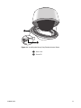
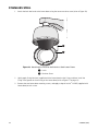
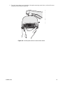
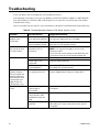
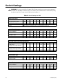
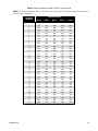
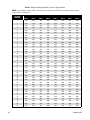
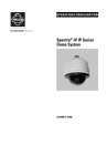
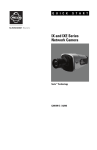
I N S T A L L A T I O N
Spectra IV IP Series
SD4E Dome System
In-Ceiling
Heavy-Duty In-Ceiling
Pendant (shown)
C3468M (4/10)
Contents
Important Notices. . . . . . . . . . . . . . . . . . . . . . . . . . . . . . . . . . . . . . . . . . . . . . . . . . . . . . . . . . . . . . . . . . . . . .
Legal Notice . . . . . . . . . . . . . . . . . . . . . . . . . . . . . . . . . . . . . . . . . . . . . . . . . . . . . . . . . . . . . . . . . . . . .
Regulatory Notices. . . . . . . . . . . . . . . . . . . . . . . . . . . . . . . . . . . . . . . . . . . . . . . . . . . . . . . . . . . . . . . .
Open Source Software Notice . . . . . . . . . . . . . . . . . . . . . . . . . . . . . . . . . . . . . . . . . . . . . . . . . . . . . . .
6
6
6
6
Description . . . . . . . . . . . . . . . . . . . . . . . . . . . . . . . . . . . . . . . . . . . . . . . . . . . . . . . . . . . . . . . . . . . . . . . . . . . 7
Models . . . . . . . . . . . . . . . . . . . . . . . . . . . . . . . . . . . . . . . . . . . . . . . . . . . . . . . . . . . . . . . . . . . . . . . . . 7
Parts List. . . . . . . . . . . . . . . . . . . . . . . . . . . . . . . . . . . . . . . . . . . . . . . . . . . . . . . . . . . . . . . . . . . . . . . . 7
Mounting . . . . . . . . . . . . . . . . . . . . . . . . . . . . . . . . . . . . . . . . . . . . . . . . . . . . . . . . . . . . . . . . . . . . . . . . . . . . 8
In-Ceiling . . . . . . . . . . . . . . . . . . . . . . . . . . . . . . . . . . . . . . . . . . . . . . . . . . . . . . . . . . . . . . . . . . . . . . . 8
Heavy-Duty In-Ceiling. . . . . . . . . . . . . . . . . . . . . . . . . . . . . . . . . . . . . . . . . . . . . . . . . . . . . . . . . . . . . . 9
Pendant, Heavy-Duty Pendant, and Stainless Steel . . . . . . . . . . . . . . . . . . . . . . . . . . . . . . . . . . . . . 11
Wiring . . . . . . . . . . . . . . . . . . . . . . . . . . . . . . . . . . . . . . . . . . . . . . . . . . . . . . . . . . . . . . . . . . . . . . . . . . . . . . 12
Installing the Dome Drive. . . . . . . . . . . . . . . . . . . . . . . . . . . . . . . . . . . . . . . . . . . . . . . . . . . . . . . . . . . . . . . 18
Installing the Lower Dome . . . . . . . . . . . . . . . . . . . . . . . . . . . . . . . . . . . . . . . . . . . . . . . . . . . . . . . . . . . . . .
In-Ceiling . . . . . . . . . . . . . . . . . . . . . . . . . . . . . . . . . . . . . . . . . . . . . . . . . . . . . . . . . . . . . . . . . . . . . .
Heavy-Duty In-Ceiling. . . . . . . . . . . . . . . . . . . . . . . . . . . . . . . . . . . . . . . . . . . . . . . . . . . . . . . . . . . . .
Pendant. . . . . . . . . . . . . . . . . . . . . . . . . . . . . . . . . . . . . . . . . . . . . . . . . . . . . . . . . . . . . . . . . . . . . . . .
Heavy-Duty Pendant. . . . . . . . . . . . . . . . . . . . . . . . . . . . . . . . . . . . . . . . . . . . . . . . . . . . . . . . . . . . . .
Stainless Steel . . . . . . . . . . . . . . . . . . . . . . . . . . . . . . . . . . . . . . . . . . . . . . . . . . . . . . . . . . . . . . . . . .
19
19
20
21
22
24
Troubleshooting . . . . . . . . . . . . . . . . . . . . . . . . . . . . . . . . . . . . . . . . . . . . . . . . . . . . . . . . . . . . . . . . . . . . . . 26
Switch Settings . . . . . . . . . . . . . . . . . . . . . . . . . . . . . . . . . . . . . . . . . . . . . . . . . . . . . . . . . . . . . . . . . . . . . . 28
Specifications . . . . . . . . . . . . . . . . . . . . . . . . . . . . . . . . . . . . . . . . . . . . . . . . . . . . . . . . . . . . . . . . . . . . . . . . 37
C3468M (4/10)
3
List of Illustrations
1
2
3
4
5
6
7
8
9
10
11
12
13
14
15
16
17
18
19
20
4
Preparing the Ceiling . . . . . . . . . . . . . . . . . . . . . . . . . . . . . . . . . . . . . . . . . . . . . . . . . . . . . . . . . . . . . . 8
Attaching the Conduit Fitting, Lock Nut, and Safety Chain Bracket . . . . . . . . . . . . . . . . . . . . . . . . . . 8
Marking the Screw Hole Pattern . . . . . . . . . . . . . . . . . . . . . . . . . . . . . . . . . . . . . . . . . . . . . . . . . . . . . 9
Installing the Plates . . . . . . . . . . . . . . . . . . . . . . . . . . . . . . . . . . . . . . . . . . . . . . . . . . . . . . . . . . . . . . 10
Installing the Heavy-Duty In-Ceiling Back Box. . . . . . . . . . . . . . . . . . . . . . . . . . . . . . . . . . . . . . . . . . 10
Attaching the Pendant Back Box to the Mount . . . . . . . . . . . . . . . . . . . . . . . . . . . . . . . . . . . . . . . . . 11
Back Box Door . . . . . . . . . . . . . . . . . . . . . . . . . . . . . . . . . . . . . . . . . . . . . . . . . . . . . . . . . . . . . . . . . . 12
Removing the TXB-N . . . . . . . . . . . . . . . . . . . . . . . . . . . . . . . . . . . . . . . . . . . . . . . . . . . . . . . . . . . . . 13
Connect the Wiring to the Circuit Board . . . . . . . . . . . . . . . . . . . . . . . . . . . . . . . . . . . . . . . . . . . . . . 14
Connecting Audio to the TXB-N . . . . . . . . . . . . . . . . . . . . . . . . . . . . . . . . . . . . . . . . . . . . . . . . . . . . . 15
Routing the Cables in the Back Box . . . . . . . . . . . . . . . . . . . . . . . . . . . . . . . . . . . . . . . . . . . . . . . . . . 16
Setting the DIP Switches . . . . . . . . . . . . . . . . . . . . . . . . . . . . . . . . . . . . . . . . . . . . . . . . . . . . . . . . . . 18
Installing the In-Ceiling Lower Dome. . . . . . . . . . . . . . . . . . . . . . . . . . . . . . . . . . . . . . . . . . . . . . . . . 19
Installing the Heavy-Duty In-Ceiling Lower Dome. . . . . . . . . . . . . . . . . . . . . . . . . . . . . . . . . . . . . . . 20
Attaching the Leash to the Pendant Lower Dome . . . . . . . . . . . . . . . . . . . . . . . . . . . . . . . . . . . . . . . 21
Installing the Pendant Lower Dome. . . . . . . . . . . . . . . . . . . . . . . . . . . . . . . . . . . . . . . . . . . . . . . . . . 21
Installing the O-Ring. . . . . . . . . . . . . . . . . . . . . . . . . . . . . . . . . . . . . . . . . . . . . . . . . . . . . . . . . . . . . . 22
Installing the Heavy-Duty Pendant Lower Dome . . . . . . . . . . . . . . . . . . . . . . . . . . . . . . . . . . . . . . . . 23
Attaching the Leash to the Stainless Steel Lower Dome . . . . . . . . . . . . . . . . . . . . . . . . . . . . . . . . . 24
Installing the Stainless Steel Lower Dome . . . . . . . . . . . . . . . . . . . . . . . . . . . . . . . . . . . . . . . . . . . . 25
C3468M (4/10)
List of Tables
A
B
C
D
E
F
Video Coaxial Cable Requirements . . . . . . . . . . . . . . . . . . . . . . . . . . . . . . . . . . . . . . . . . . . . . . . . . .
24 VAC/24 VDC Wiring Distances . . . . . . . . . . . . . . . . . . . . . . . . . . . . . . . . . . . . . . . . . . . . . . . . . . .
Troubleshooting the Spectra IV IP Dome System . . . . . . . . . . . . . . . . . . . . . . . . . . . . . . . . . . . . . . .
Switch Settings for SW2 . . . . . . . . . . . . . . . . . . . . . . . . . . . . . . . . . . . . . . . . . . . . . . . . . . . . . . . . . .
Switch Settings for SW1, Pelco P-Type Control . . . . . . . . . . . . . . . . . . . . . . . . . . . . . . . . . . . . . . . .
Switch Settings for SW1, Pelco D-Type Control . . . . . . . . . . . . . . . . . . . . . . . . . . . . . . . . . . . . . . . .
C3468M (4/10)
17
17
26
28
29
30
5
Important Notices
LEGAL NOTICE
SOME PELCO EQUIPMENT CONTAINS, AND THE SOFTWARE ENABLES, AUDIO/VISUAL AND RECORDING
CAPABILITIES, THE IMPROPER USE OF WHICH MAY SUBJECT YOU TO CIVIL AND CRIMINAL PENALTIES.
APPLICABLE LAWS REGARDING THE USE OF SUCH CAPABILITIES VARY BETWEEN JURISDICTIONS AND
MAY REQUIRE, AMONG OTHER THINGS, EXPRESS WRITTEN CONSENT FROM RECORDED SUBJECTS.
YOU ARE SOLELY RESPONSIBLE FOR INSURING STRICT COMPLIANCE WITH SUCH LAWS AND FOR
STRICT ADHERENCE TO ANY/ALL RIGHTS OF PRIVACY AND PERSONALTY. USE OF THIS EQUIPMENT
AND/OR SOFTWARE FOR ILLEGAL SURVEILLANCE OR MONITORING SHALL BE DEEMED UNAUTHORIZED
USE IN VIOLATION OF THE END USER SOFTWARE AGREEMENT AND RESULT IN THE IMMEDIATE
TERMINATION OF YOUR LICENSE RIGHTS THEREUNDER.
REGULATORY NOTICES
This device complies with Part 15 of the FCC Rules. Operation is subject to the following two conditions:
(1) this device may not cause harmful interference, and (2) this device must accept any interference
received, including interference that may cause undesired operation.
RADIO AND TELEVISION INTERFERENCE
This equipment has been tested and found to comply with the limits of a Class B digital device, pursuant to
Part 15 of the FCC Rules. These limits are designed to provide reasonable protection against harmful
interference in a residential installation. This equipment generates, uses, and can radiate radio frequency
energy and, if not installed and used in accordance with the instructions, may cause harmful interference to
radio communications. However there is no guarantee that the interference will not occur in a particular
installation. If this equipment does cause harmful interference to radio or television reception, which can be
determined by turning the equipment off and on, the user is encouraged to try to correct the interference by
one or more of the following measures:
•
Reorient or relocate the receiving antenna.
•
Increase the separation between the equipment and the receiver.
•
Connect the equipment into an outlet on a circuit different from that to which the receiver is connected.
•
Consult the dealer or an experienced radio/TV technician for help.
You may also find helpful the following booklet, prepared by the FCC: “How to Identify and Resolve
Radio-TV Interference Problems.” This booklet is available from the U.S. Government Printing Office,
Washington D.C. 20402.
Changes and modifications not expressly approved by the manufacturer or registrant of this equipment can
void your authority to operate this equipment under Federal Communications Commission’s rules.
This Class B digital apparatus complies with Canadian ICES-003.
Cet appareil numérique de la classe B est conforme à la norme NMB-003 du Canada.
OPEN SOURCE SOFTWARE NOTICE
This product includes certain open source or other software originated from third parties that is subject to
the GNU General Public License (GPL), GNU Library/Lesser General Public License (LGPL) and different
and/or additional copyright licenses, disclaimers and notices.
The exact terms of GPL, LGPL and some other licenses are provided to you with this product. Please refer
to the exact terms of the GPL and LGPL at www.fsf.org (Free Software Foundation) and
www.opensource.org (Open Source Initiative) regarding your rights under said license. You may obtain a
complete corresponding machine-readable copy of the source code of such software under the GPL or
LGPL by sending your request to [email protected] and the subject line should read Source Code
Request. You will then receive a link in the e-mail for you to download the source code.
This offer is valid for a period of three (3) years from the date of the distribution of this product by Pelco.
6
C3468M (4/10)
Description
Spectra® IV IP was designed with ease of installation and ease of maintenance in mind. Each dome
system consists of three components: a back box, a dome drive, and a lower dome. Spectra IV IP back box
options include the following models: environmental in-ceiling (ideal for outdoor soffits), indoor in-ceiling,
standard and environmental pendant, heavy-duty, and stainless steel. Depending on the dome drive model
with which it will be used, a back box can be ordered with or without built-in back box memory. This
memory can be used to store camera and location-specific dome settings, including labels, presets,
patterns, and zones.
MODELS
BB4E-F
BB4E-F-E
BB4E-PB
BB4E-PG
BB4E-PG-E
BB4EHD-F
BB4EHD-PG
BB4EHD-PG-E
BB4E-PSG-E
In-ceiling, black, with back box memory
In-ceiling, black, environmental, with back box memory
Pendant mount, black, standard, with back box memory
Pendant mount, gray, standard, with back box memory
Pendant mount, gray, environmental, with back box memory
Heavy-duty, in-ceiling, gray, with back box memory
Heavy-duty, pendant, gray, with back box memory
Heavy-duty, environmental pendant, gray, with back box memory
Stainless steel, environmental pendant, gray 316 SS, with back box memory
PARTS LIST
Qty
1
1
8
1
1
1
1
Description
Back box
Thread compound (pendant, heavy-duty pendant, and stainless steel models only)
Screws, 10-32 x 3-inch, Phillips flat head (heavy-duty in-ceiling model only)
Important Safety Instructions manual
Installation manual
Operation/Configuration manual
Resource disc
C3468M (4/10)
7
Mounting
IN-CEILING
1. Prepare the ceiling (refer to Figure 1):
a.
Locate the center point of the mounting location, and insert the compass tool into the ceiling.
b.
Place the end of a pencil in the hole on the end of the compass tool, and draw a circle.
c.
Cut out the circle.
Figure 1. Preparing the Ceiling
2. Attach a conduit fitting (not supplied), lock nut (not supplied), and safety chain bracket (refer to
Figure 2).
3. Install a safety chain/cable (not supplied), which will support up to 16 pounds (7.3 kg).
Figure 2. Attaching the Conduit Fitting, Lock Nut, and Safety Chain Bracket
8
C3468M (4/10)
4. Open the hinged door to the back box by pushing the tab lock toward the wall of the unit and lifting
the door open.
5. Pull the wiring into the back box through the conduit fitting.
6. Connect all required wiring (refer to Wiring on page 12).
7. Install the back box by compressing the spring clips and pushing the back box through the hole.
8. Tighten the screws until you hear a clicking noise.
HEAVY-DUTY IN-CEILING
1. Prepare the ceiling (refer to Figure 1 on page 8):
a.
Locate the center point of the mounting location, and insert the compass tool into the ceiling.
b.
Place the end of a pencil in the hole on the end of the compass tool, and draw a circle.
c.
Cut out the circle.
2. Use the mounting ring as a template to mark the screw hole pattern onto the mounting surface.
3. Prepare the holes.
Figure 3. Marking the Screw Hole Pattern
4. Install the mounting plates (refer to Figure 4 on page 10). Use the eight 10-32 x 3-inch screws
(supplied) to install the mounting ring and the two back mounting plates.
a.
Line up the mounting ring with the eight fastener holes.
b.
Feed one back mounting plate through the hole in the ceiling. Line up the plate with the four
fastener holes.
c.
Install fasteners through the mounting ring, ceiling, and out the back mounting plate.
d.
Install the second back mounting plate.
C3468M (4/10)
9
Figure 4. Installing the Plates
ì Back Mounting Plates
î Ceiling
ï Mounting Ring
5. Attach a conduit fitting (not supplied), lock nut (not supplied), and safety chain bracket (refer to
Figure 2 on page 8).
6. Install a safety chain/cable (not supplied), which will support up to 16 pounds (7.3 kg).
7. Open the hinged door to the back box by pushing the tab lock toward the wall of the unit and lifting
the door open.
8. Pull the wiring into the back box through the conduit fitting.
9. Connect all required wiring (refer to Wiring on page 12).
10. Install the back box by compressing the spring clips and pushing the back box through the hole (refer
to Figure 5).
11. Tighten the screws until you hear a clicking noise.
Figure 5. Installing the Heavy-Duty In-Ceiling Back Box
10
C3468M (4/10)
PENDANT, HEAVY-DUTY PENDANT, AND STAINLESS STEEL
1. Install the mount for the pendant dome. Refer to the instructions supplied with the mount.
NOTE: If the mount is outdoors, make sure it is properly sealed to keep moisture out.
2. Open the hinged door to the back box by pushing the tab lock towards the wall of the unit and lifting
the door open.
3. Pull the wiring into the back box.
4. Connect all required wiring (refer to Wiring on page 12).
5. Screw the back box onto the mount (refer to Figure 6). If outdoors, apply thread compound (supplied)
to the threads on the back box.
NOTE: Thread compound must be applied. Not doing so may prevent the units from being separated
in the future.
Figure 6. Attaching the Pendant Back Box to the Mount
C3468M (4/10)
11
Wiring
1. Open the hinged door to the back box by pushing the tab lock toward the wall of the unit and lifting
the door open (refer to Figure 7).
Figure 7. Back Box Door
12
C3468M (4/10)
2. Remove the TXB-N from the back box circuit board (refer to Figure 8):
a.
Loosen the captive screw on the TXB-N.
b.
Carefully unplug the TXB-N from the back box circuit board.
+-
Figure 8. Removing the TXB-N
C3468M (4/10)
ì RJ-45 Connector
î Ethernet Cable
s Standoff
t UTP Connector
ï Video Coaxial Cable
ñ 16-Pin Connector
u Back Box Circuit Board
~í Audio Connectors
ó Heat Sink Standoff
r Captive Screw
~â TXB-N
13
3. Connect the auxiliary, alarm, and other wiring to the back box circuit board (refer to Figure 9).
NOTES:
•
•
ALARMS
AUX1
Aux 1: Maximum 2 A at low voltage (<40 V)
Aux 2: Maximum 30 mA at 32 VDC
If you are installing an environmental back box in a railway application, attach a ground wire
from the circuit board power connector to a structural ground using at least 18-gauge wire.
1
2
3
4
5
6
7
GND
NO
COM
NC
AUX2
GND
VIDEO
PWR- GND PWR+ RX- RX+ TX- TX+ UTP+ UTP-
Figure 9. Connect the Wiring to the Circuit Board
14
C3468M (4/10)
4. If you plan to use the audio functions, install your audio cables into the audio line-in and line-out
connectors on the TXB-N.
NOTES:
•
•
To take full advantage of the distance and noise immunity benefits of audio, you must use a
600-ohm impedance matching transformer and twisted pair cable (refer to Figure 10).
A stable power supply is required for optimal audio performance.
Figure 10. Connecting Audio to the TXB-N
ì Microphone
î Amplifier
ó Line-Out Audio Twisted Pair Cable
r 600-Ohm Impedance Matching Transformer
ï 600-Ohm Impedance Matching Transformer s Amplifier
ñ Line-In Audio Twisted Pair Cable
t Speaker
C3468M (4/10)
15
5. Reinstall the TXB-N:
a.
Plug the TXB-N into the 16-pin connector located on the back box circuit board.
b.
Secure the TXB-N to the standoff on the circuit board using the captive screw on the TXB-N.
6. Plug your network Ethernet cable into the RJ-45 connector on the TXB-N to connect the Spectra IV
dome system to your existing network.
WARNING: An electrical short in the back box may occur if the metal BNC connector on the video
coaxial cable is not completely covered by the protective boot.
7. Perform one of the following options:
•
•
View video using both analog and IP connections: Connect the video coaxial cable from
the back box circuit board to the coaxial cable coming in from the outside. Make sure that the
BNC connector is completely covered by the protective boot.
View video using only the IP connection: Make sure that the BNC connector is
completely covered by the protective boot and is out of the way of the back box door.
8. Before closing the interconnect door, ensure that no wires are between the top of the heat sink
standoff and the back box (refer to Figure 11 on page 16). Both the video coaxial cable and the
Ethernet cable need to be routed carefully to ensure clearance for the heat sink standoff.
9. Close the interconnect door and snap the tab lock into place.
Figure 11. Routing the Cables in the Back Box
ì RJ-45 Connector
î Ethernet Cable
ï Video Coaxial Cable
16
C3468M (4/10)
Table A. Video Coaxial Cable Requirements
Cable Type*
Maximum Distance
RG59/U
750 ft (229 m)
RG6/U
1,000 ft (305 m)
RG11/U
1,500 ft (457 m)
*Cable requirements:
• 75-ohm impedance
• All-copper center conductor
• All-copper braided shield with
95 percent braid coverage
Refer to Table B for the recommended maximum distances for 24 VAC and 24 VDC applications, which are
calculated with a 10 percent voltage drop. (Ten percent is generally the maximum allowable voltage drop
for AC- or DC-powered devices.)
Table B. 24 VAC/24 VDC Wiring Distances
Wire Gauge
AC/DC
Total VA/
Total Watts
20 AWG
(0.5 mm2)
18 AWG
(1.0 mm2)
16 AWG
(1.5 mm2)
14 AWG
(2.5 mm2)
23 VA/
15 W
123 ft
(38 m)
196 ft
(60 m)
311 ft
(95 m)
495 ft
(151 m)
73 VA/
65 W
39 ft
(12 m)
62 ft
(19 m)
98 ft
(30 m)
156 ft
(48 m)
NOTE: Input power for the dome is 24 VAC or 24 VDC. Using 24 VAC input power,
power consumption is 23 VA per dome for indoor models and 73 VA for outdoor models.
Using 24 VDC input power, power consumption is 0.7 A (15 W) for indoor models and
3 A (65 W) for outdoor models.
Use a 24 VAC transformer with the following minimum VA:
•
40 VA per dome: For indoor models (without heater)
•
100 VA per dome: For outdoor models (with heater)
C3468M (4/10)
17
Installing the Dome Drive
1. Perform one of the following options:
•
•
View video using both analog and IP connections: Set the DIP switches on the top of
the Spectra IV dome drive (refer to Figure 12). For DIP switch settings, refer to the labels
located on the top of the dome drive, or refer to Switch Settings on page 28.
View video using the IP connection: You do not need to set the DIP switches.
NOTE: When connecting more than one Spectra dome to a single controller, terminate the unit
farthest from the controller. To terminate the dome drive set the SW2-10 switch to the ON position.
Figure 12. Setting the DIP Switches
2. Install the dome drive.
WARNING: Improper installation of the dome drive can be dangerous and can seriously damage
the equipment.
18
a.
Align the blue and red tabs with the blue and red labels on the back box.
b.
Push in the red tab and insert that side of the dome drive first.
c.
Push in the blue tab and insert the dome drive into the back box the remainder of the way.
d.
Continue pushing on the ends of the tabs until both sides click firmly into place.
C3468M (4/10)
Installing the Lower Dome
IN-CEILING
1. Snap the clip on the end of the trim ring leash into the hole on the lip of the back box (refer to
Figure 13).
Figure 13. Installing the In-Ceiling Lower Dome
2. Snap the trim ring into the plastic snap washers on the mounting screws.
C3468M (4/10)
19
HEAVY-DUTY IN-CEILING
1. Snap the clip of the lower trim ring leash into the hole on the lip of the back box (refer to Figure 14).
2. Insert both keys in the barrel locks. Turn the keys clockwise to the unlocked position.
NOTE: Keys cannot be removed from the lock while in the unlocked position.
3. Align the ball studs, located on the mount ring, with the ball stud receivers, located on the inside of
the lower dome. Push the lower dome into the back box.
4. Hold and turn both keys to the locked position.
Figure 14. Installing the Heavy-Duty In-Ceiling Lower Dome
ì Trim Leash
î Ball Stud
ï Ball Stud Receiver
ñ Barrel Key Lock
20
C3468M (4/10)
PENDANT
1. Attach the back box leash to the lower dome (refer to Figure 15).
Figure 15. Attaching the Leash to the Pendant Lower Dome
2. Push the lower dome into the back box.
3. Tighten the captive Phillips pan head screws to secure the lower dome.
Figure 16. Installing the Pendant Lower Dome
C3468M (4/10)
21
HEAVY-DUTY PENDANT
1. Attach the back box leash to the lower dome (refer to Figure 15 on page 21).
2. Lightly apply O-ring lubricant (supplied with the lower dome) to the O-ring, and then install the
O-ring in the groove on the trim ring of the lower dome (refer to Figure 17).
Figure 17. Installing the O-Ring
3. Align the barrel locks in the lower dome with the holes located on each side of the back box (refer to
Figure 18 on page 23).
4. Push the lower dome into the back box.
5. Press in the pins of the barrel locks to secure the lower dome.
22
C3468M (4/10)
Figure 18. Installing the Heavy-Duty Pendant Lower Dome
ì Barrel Lock
î Center Pin
C3468M (4/10)
23
STAINLESS STEEL
1. Attach the back box leash to the lower dome using the nearest retainer screw (refer to Figure 19).
Figure 19. Attaching the Leash to the Stainless Steel Lower Dome
ì Leash
î Retainer Screw
2. Lightly apply O-ring lubricant (supplied with the lower dome) to the O-ring, and then install the
O ring in the groove on the trim ring of the lower dome (refer to Figure 17 on page 22).
3. Remove the two lower dome mounting screws, and apply a drop of Loctite® 222MS (supplied with
lower dome) to each screw.
24
C3468M (4/10)
4. Push the lower dome into the back box, line up the mounting screw holes, and install the two
mounting screws (refer to Figure 20).
Figure 20. Installing the Stainless Steel Lower Dome
C3468M (4/10)
25
Troubleshooting
To use your dome, refer to the operation and configuration manual.
If the following instructions fail to solve your problem, contact Pelco Product Support at 1-800-289-9100
(USA and Canada) or +1-559-292-1981 (international) for assistance. Be sure to have the serial number
available when calling.
Do not try to repair the unit yourself. Leave maintenance and repairs to qualified technical personnel only.
Table C. Troubleshooting the Spectra IV IP Dome System (1 of 2)
Problem
Possible Causes
Suggested Resolution
Dome does not start
properly after
installation.
The circuit board fuse
may need to be replaced.
Check the fuse on the circuit board inside the back box
for continuity. Replace the fuse if needed.
The back box may not be
receiving proper voltage.
Check the wiring with a volt meter to ensure that the
back box is receiving proper voltage.
Dome starts correctly,
but you do not have
accurate control.
Switch settings on the
dome drive are set
incorrectly.
Check the signal with a volt meter or an oscilloscope.
NOTE: This step will not apply if you are using
Coaxitron control.
Ensure that the switch settings on the dome drive are
set correctly (refer to Switch Settings on page 28.)
No video is displayed.
Power is not connected.
Check the power connector.
Video cable is not
connected.
Check the video connector.
TXB-N module is not
inserted properly.
Reinstall the TXB-N module. Make sure the pins on
the module are inserted correctly.
Spectra IV information
(model, firmware,
Pelco P and Pelco D
protocol addresses,
and communication
settings) does not
appear after the
configuration cycle.
The unit cannot complete
its configuration cycle.
Refer to Troubleshooting in the Installation/Operation
manual shipped with the Spectra IV dome drive.
The audio signal is
weak.
You are not using the
correct type of
transformer.
Be sure you are using a 600-ohm impedance matching
transformer.
The wiring distance
connecting the audio
equipment may be too
long.
Test the equipment using a shorter wiring distance.
The gain is not properly
adjusted.
If you are using an external amplifier and it has an
adjustable gain, increase the gain until the signal is
acceptable.
26
C3468M (4/10)
Table C. Troubleshooting the Spectra IV IP Dome System (2 of 2)
Problem
Possible Causes
Suggested Resolution
There is an echo when
audio is received.
The speaker volume is
too high.
Lower the speaker volume.
The microphone and the
speaker are too close
together.
If your call station does not have built-in echo
cancellation, move the microphone and speaker
farther apart.
Your call station does not
have built-in echo
cancellation.
Use a call station with built-in echo cancellation.
C3468M (4/10)
27
Switch Settings
WARNING: If you are using Pelco D-type or Pelco P-type control, your system may not operate if
the baud rate and address switches are not set correctly. The switches are set at the factory using
the defaults for Pelco D-type control (2400 baud and address 1).
Table D. Switch Settings for SW2
Special Systems
Switch Number
AD-32 Preset System
1
3
4
5
6
7
8
9
10
ON
CM9502 Setting
Vicon™
2
ON
Not currently available; SW2-3 is reserved for future use.
Serial Port Settings
Switch Number
4
5
RS422
1
2
3
OFF
OFF
6
7
8
9
10
RS485, 4-Wire
OFF
ON
RS485, 2-Wire
ON
ON
4
5
6
7
8
9
10
2400 Baud
(Default for D-type Control)
OFF
OFF
OFF
4800 Baud
(Default for P-type Control)
ON
OFF
OFF
9600 Baud
OFF
ON
OFF
6
7
8
9
10
Pelco D or Pelco P Protocol Baud Rate
Switch Number
1
2
3
Video Cable Type
Switch Number
1
2
3
4
5
Coaxial Cable
OFF
Dome Termination
Switch Number
28
1
2
3
4
5
6
7
8
9
10
Terminated
ON
Not Terminated
OFF
C3468M (4/10)
Table E. Switch Settings for SW1, Pelco P-Type Control
NOTE: For Coaxitron controls, SW1 is not used; set all switches to OFF. For Pelco D-type control systems,
refer to Table F on page 30.
C3468M (4/10)
SWITCH SETTING
SPECTRA
ADDRESS
SW1-1
SW1-2
SW1-3
SW1-4
1
OFF
OFF
OFF
OFF
OFF
2
ON
OFF
OFF
OFF
OFF
3
OFF
ON
OFF
OFF
OFF
4
ON
ON
OFF
OFF
OFF
5
OFF
OFF
ON
OFF
OFF
6
ON
OFF
ON
OFF
OFF
7
OFF
ON
ON
OFF
OFF
8
ON
ON
ON
OFF
OFF
SW1-5
9
OFF
OFF
OFF
ON
OFF
10
ON
OFF
OFF
ON
OFF
11
OFF
ON
OFF
ON
OFF
12
ON
ON
OFF
ON
OFF
13
OFF
OFF
ON
ON
OFF
14
ON
OFF
ON
ON
OFF
15
OFF
ON
ON
ON
OFF
16
ON
ON
ON
ON
OFF
17
OFF
OFF
OFF
OFF
ON
18
ON
OFF
OFF
OFF
ON
19
OFF
ON
OFF
OFF
ON
20
ON
ON
OFF
OFF
ON
21
OFF
OFF
ON
OFF
ON
22
ON
OFF
ON
OFF
ON
23
OFF
ON
ON
OFF
ON
24
ON
ON
ON
OFF
ON
25
OFF
OFF
OFF
ON
ON
26
ON
OFF
OFF
ON
ON
27
OFF
ON
OFF
ON
ON
28
ON
ON
OFF
ON
ON
29
OFF
OFF
ON
ON
ON
ON
30
ON
OFF
ON
ON
31
OFF
ON
ON
ON
ON
32
ON
ON
ON
ON
ON
29
Table F. Switch Settings for SW1, Pelco D-Type Control
NOTE: For Coaxitron controls, SW1 is not used; set all switches to OFF. For Pelco P-type control systems,
refer to Table E on page 29.
30
SWITCH SETTING
SPECTRA
ADDRESS
SW1-1
SW1-2
SW1-3
SW1-4
SW1-5
SW1-6
SW1-7
1
ON
OFF
OFF
OFF
OFF
OFF
OFF
OFF
2
OFF
ON
OFF
OFF
OFF
OFF
OFF
OFF
SW1-8
3
ON
ON
OFF
OFF
OFF
OFF
OFF
OFF
4
OFF
OFF
ON
OFF
OFF
OFF
OFF
OFF
5
ON
OFF
ON
OFF
OFF
OFF
OFF
OFF
6
OFF
ON
ON
OFF
OFF
OFF
OFF
OFF
7
ON
ON
ON
OFF
OFF
OFF
OFF
OFF
8
OFF
OFF
OFF
ON
OFF
OFF
OFF
OFF
9
ON
OFF
OFF
ON
OFF
OFF
OFF
OFF
10
OFF
ON
OFF
ON
OFF
OFF
OFF
OFF
11
ON
ON
OFF
ON
OFF
OFF
OFF
OFF
12
OFF
OFF
ON
ON
OFF
OFF
OFF
OFF
13
ON
OFF
ON
ON
OFF
OFF
OFF
OFF
14
OFF
ON
ON
ON
OFF
OFF
OFF
OFF
15
ON
ON
ON
ON
OFF
OFF
OFF
OFF
16
OFF
OFF
OFF
OFF
ON
OFF
OFF
OFF
17
ON
OFF
OFF
OFF
ON
OFF
OFF
OFF
18
OFF
ON
OFF
OFF
ON
OFF
OFF
OFF
19
ON
ON
OFF
OFF
ON
OFF
OFF
OFF
20
OFF
OFF
ON
OFF
ON
OFF
OFF
OFF
21
ON
OFF
ON
OFF
ON
OFF
OFF
OFF
22
OFF
ON
ON
OFF
ON
OFF
OFF
OFF
23
ON
ON
ON
OFF
ON
OFF
OFF
OFF
24
OFF
OFF
OFF
ON
ON
OFF
OFF
OFF
25
ON
OFF
OFF
ON
ON
OFF
OFF
OFF
26
OFF
ON
OFF
ON
ON
OFF
OFF
OFF
27
ON
ON
OFF
ON
ON
OFF
OFF
OFF
28
OFF
OFF
ON
ON
ON
OFF
OFF
OFF
29
ON
OFF
ON
ON
ON
OFF
OFF
OFF
30
OFF
ON
ON
ON
ON
OFF
OFF
OFF
31
ON
ON
ON
ON
ON
OFF
OFF
OFF
32
OFF
OFF
OFF
OFF
OFF
ON
OFF
OFF
33
ON
OFF
OFF
OFF
OFF
ON
OFF
OFF
34
OFF
ON
OFF
OFF
OFF
ON
OFF
OFF
35
ON
ON
OFF
OFF
OFF
ON
OFF
OFF
36
OFF
OFF
ON
OFF
OFF
ON
OFF
OFF
37
ON
OFF
ON
OFF
OFF
ON
OFF
OFF
C3468M (4/10)
SWITCH SETTING
SPECTRA
ADDRESS
SW1-1
SW1-2
SW1-3
SW1-4
SW1-5
SW1-6
SW1-7
SW1-8
38
OFF
ON
ON
OFF
OFF
ON
OFF
OFF
39
ON
ON
ON
OFF
OFF
ON
OFF
OFF
40
OFF
OFF
OFF
ON
OFF
ON
OFF
OFF
41
ON
OFF
OFF
ON
OFF
ON
OFF
OFF
42
OFF
ON
OFF
ON
OFF
ON
OFF
OFF
43
ON
ON
OFF
ON
OFF
ON
OFF
OFF
44
OFF
OFF
ON
ON
OFF
ON
OFF
OFF
45
ON
OFF
ON
ON
OFF
ON
OFF
OFF
46
OFF
ON
ON
ON
OFF
ON
OFF
OFF
47
ON
ON
ON
ON
OFF
ON
OFF
OFF
48
OFF
OFF
OFF
OFF
ON
ON
OFF
OFF
49
ON
OFF
OFF
OFF
ON
ON
OFF
OFF
50
OFF
ON
OFF
OFF
ON
ON
OFF
OFF
51
ON
ON
OFF
OFF
ON
ON
OFF
OFF
52
OFF
OFF
ON
OFF
ON
ON
OFF
OFF
53
ON
OFF
ON
OFF
ON
ON
OFF
OFF
54
OFF
ON
ON
OFF
ON
ON
OFF
OFF
55
ON
ON
ON
OFF
ON
ON
OFF
OFF
56
OFF
OFF
OFF
ON
ON
ON
OFF
OFF
57
ON
OFF
OFF
ON
ON
ON
OFF
OFF
58
OFF
ON
OFF
ON
ON
ON
OFF
OFF
59
ON
ON
OFF
ON
ON
ON
OFF
OFF
60
OFF
OFF
ON
ON
ON
ON
OFF
OFF
61
ON
OFF
ON
ON
ON
ON
OFF
OFF
62
OFF
ON
ON
ON
ON
ON
OFF
OFF
63
ON
ON
ON
ON
ON
ON
OFF
OFF
64
OFF
OFF
OFF
OFF
OFF
OFF
ON
OFF
65
ON
OFF
OFF
OFF
OFF
OFF
ON
OFF
66
OFF
ON
OFF
OFF
OFF
OFF
ON
OFF
67
ON
ON
OFF
OFF
OFF
OFF
ON
OFF
68
OFF
OFF
ON
OFF
OFF
OFF
ON
OFF
69
ON
OFF
ON
OFF
OFF
OFF
ON
OFF
70
OFF
ON
ON
OFF
OFF
OFF
ON
OFF
71
ON
ON
ON
OFF
OFF
OFF
ON
OFF
72
OFF
OFF
OFF
ON
OFF
OFF
ON
OFF
73
ON
OFF
OFF
ON
OFF
OFF
ON
OFF
74
OFF
ON
OFF
ON
OFF
OFF
ON
OFF
75
ON
ON
OFF
ON
OFF
OFF
ON
OFF
76
OFF
OFF
ON
ON
OFF
OFF
ON
OFF
77
ON
OFF
ON
ON
OFF
OFF
ON
OFF
78
OFF
ON
ON
ON
OFF
OFF
ON
OFF
C3468M (4/10)
31
SPECTRA
ADDRESS
32
SWITCH SETTING
SW1-1
SW1-2
SW1-3
SW1-4
SW1-5
SW1-6
SW1-7
SW1-8
79
ON
ON
ON
ON
OFF
OFF
ON
OFF
80
OFF
OFF
OFF
OFF
ON
OFF
ON
OFF
81
ON
OFF
OFF
OFF
ON
OFF
ON
OFF
82
OFF
ON
OFF
OFF
ON
OFF
ON
OFF
83
ON
ON
OFF
OFF
ON
OFF
ON
OFF
84
OFF
OFF
ON
OFF
ON
OFF
ON
OFF
85
ON
OFF
ON
OFF
ON
OFF
ON
OFF
86
OFF
ON
ON
OFF
ON
OFF
ON
OFF
87
ON
ON
ON
OFF
ON
OFF
ON
OFF
88
OFF
OFF
OFF
ON
ON
OFF
ON
OFF
89
ON
OFF
OFF
ON
ON
OFF
ON
OFF
90
OFF
ON
OFF
ON
ON
OFF
ON
OFF
91
ON
ON
OFF
ON
ON
OFF
ON
OFF
92
OFF
OFF
ON
ON
ON
OFF
ON
OFF
93
ON
OFF
ON
ON
ON
OFF
ON
OFF
94
OFF
ON
ON
ON
ON
OFF
ON
OFF
95
ON
ON
ON
ON
ON
OFF
ON
OFF
96
OFF
OFF
OFF
OFF
OFF
ON
ON
OFF
97
ON
OFF
OFF
OFF
OFF
ON
ON
OFF
98
OFF
ON
OFF
OFF
OFF
ON
ON
OFF
99
ON
ON
OFF
OFF
OFF
ON
ON
OFF
100
OFF
OFF
ON
OFF
OFF
ON
ON
OFF
101
ON
OFF
ON
OFF
OFF
ON
ON
OFF
102
OFF
ON
ON
OFF
OFF
ON
ON
OFF
103
ON
ON
ON
OFF
OFF
ON
ON
OFF
104
OFF
OFF
OFF
ON
OFF
ON
ON
OFF
105
ON
OFF
OFF
ON
OFF
ON
ON
OFF
106
OFF
ON
OFF
ON
OFF
ON
ON
OFF
107
ON
ON
OFF
ON
OFF
ON
ON
OFF
108
OFF
OFF
ON
ON
OFF
ON
ON
OFF
109
ON
OFF
ON
ON
OFF
ON
ON
OFF
110
OFF
ON
ON
ON
OFF
ON
ON
OFF
111
ON
ON
ON
ON
OFF
ON
ON
OFF
112
OFF
OFF
OFF
OFF
ON
ON
ON
OFF
113
ON
OFF
OFF
OFF
ON
ON
ON
OFF
114
OFF
ON
OFF
OFF
ON
ON
ON
OFF
115
ON
ON
OFF
OFF
ON
ON
ON
OFF
116
OFF
OFF
ON
OFF
ON
ON
ON
OFF
117
ON
OFF
ON
OFF
ON
ON
ON
OFF
118
OFF
ON
ON
OFF
ON
ON
ON
OFF
119
ON
ON
ON
OFF
ON
ON
ON
OFF
C3468M (4/10)
SWITCH SETTING
SPECTRA
ADDRESS
SW1-1
SW1-2
SW1-3
SW1-4
SW1-5
SW1-6
SW1-7
SW1-8
120
OFF
OFF
OFF
ON
ON
ON
ON
OFF
121
ON
OFF
OFF
ON
ON
ON
ON
OFF
122
OFF
ON
OFF
ON
ON
ON
ON
OFF
123
ON
ON
OFF
ON
ON
ON
ON
OFF
124
OFF
OFF
ON
ON
ON
ON
ON
OFF
125
ON
OFF
ON
ON
ON
ON
ON
OFF
126
OFF
ON
ON
ON
ON
ON
ON
OFF
127
ON
ON
ON
ON
ON
ON
ON
OFF
128
OFF
OFF
OFF
OFF
OFF
OFF
OFF
ON
129
ON
OFF
OFF
OFF
OFF
OFF
OFF
ON
130
OFF
ON
OFF
OFF
OFF
OFF
OFF
ON
ON
131
ON
ON
OFF
OFF
OFF
OFF
OFF
132
OFF
OFF
ON
OFF
OFF
OFF
OFF
ON
133
ON
OFF
ON
OFF
OFF
OFF
OFF
ON
134
OFF
ON
ON
OFF
OFF
OFF
OFF
ON
135
ON
ON
ON
OFF
OFF
OFF
OFF
ON
136
OFF
OFF
OFF
ON
OFF
OFF
OFF
ON
137
ON
OFF
OFF
ON
OFF
OFF
OFF
ON
138
OFF
ON
OFF
ON
OFF
OFF
OFF
ON
139
ON
ON
OFF
ON
OFF
OFF
OFF
ON
140
OFF
OFF
ON
ON
OFF
OFF
OFF
ON
141
ON
OFF
ON
ON
OFF
OFF
OFF
ON
142
OFF
ON
ON
ON
OFF
OFF
OFF
ON
143
ON
ON
ON
ON
OFF
OFF
OFF
ON
144
OFF
OFF
OFF
OFF
ON
OFF
OFF
ON
145
ON
OFF
OFF
OFF
ON
OFF
OFF
ON
146
OFF
ON
OFF
OFF
ON
OFF
OFF
ON
147
ON
ON
OFF
OFF
ON
OFF
OFF
ON
148
OFF
OFF
ON
OFF
ON
OFF
OFF
ON
149
ON
OFF
ON
OFF
ON
OFF
OFF
ON
150
OFF
ON
ON
OFF
ON
OFF
OFF
ON
151
ON
ON
ON
OFF
ON
OFF
OFF
ON
152
OFF
OFF
OFF
ON
ON
OFF
OFF
ON
153
ON
OFF
OFF
ON
ON
OFF
OFF
ON
154
OFF
ON
OFF
ON
ON
OFF
OFF
ON
ON
155
ON
ON
OFF
ON
ON
OFF
OFF
156
OFF
OFF
ON
ON
ON
OFF
OFF
ON
157
ON
OFF
ON
ON
ON
OFF
OFF
ON
158
OFF
ON
ON
ON
ON
OFF
OFF
ON
159
ON
ON
ON
ON
ON
OFF
OFF
ON
160
OFF
OFF
OFF
OFF
OFF
ON
OFF
ON
C3468M (4/10)
33
SPECTRA
ADDRESS
34
SWITCH SETTING
SW1-1
SW1-2
SW1-3
SW1-4
SW1-5
SW1-6
SW1-7
SW1-8
161
ON
OFF
OFF
OFF
OFF
ON
OFF
ON
162
OFF
ON
OFF
OFF
OFF
ON
OFF
ON
ON
163
ON
ON
OFF
OFF
OFF
ON
OFF
164
OFF
OFF
ON
OFF
OFF
ON
OFF
ON
165
ON
OFF
ON
OFF
OFF
ON
OFF
ON
166
OFF
ON
ON
OFF
OFF
ON
OFF
ON
167
ON
ON
ON
OFF
OFF
ON
OFF
ON
168
OFF
OFF
OFF
ON
OFF
ON
OFF
ON
169
ON
OFF
OFF
ON
OFF
ON
OFF
ON
170
OFF
ON
OFF
ON
OFF
ON
OFF
ON
171
ON
ON
OFF
ON
OFF
ON
OFF
ON
172
OFF
OFF
ON
ON
OFF
ON
OFF
ON
173
ON
OFF
ON
ON
OFF
ON
OFF
ON
174
OFF
ON
ON
ON
OFF
ON
OFF
ON
175
ON
ON
ON
ON
OFF
ON
OFF
ON
176
OFF
OFF
OFF
OFF
ON
ON
OFF
ON
177
ON
OFF
OFF
OFF
ON
ON
OFF
ON
178
OFF
ON
OFF
OFF
ON
ON
OFF
ON
179
ON
ON
OFF
OFF
ON
ON
OFF
ON
180
OFF
OFF
ON
OFF
ON
ON
OFF
ON
ON
181
ON
OFF
ON
OFF
ON
ON
OFF
182
OFF
ON
ON
OFF
ON
ON
OFF
ON
183
ON
ON
ON
OFF
ON
ON
OFF
ON
184
OFF
OFF
OFF
ON
ON
ON
OFF
ON
185
ON
OFF
OFF
ON
ON
ON
OFF
ON
186
OFF
ON
OFF
ON
ON
ON
OFF
ON
ON
187
ON
ON
OFF
ON
ON
ON
OFF
188
OFF
OFF
ON
ON
ON
ON
OFF
ON
189
ON
OFF
ON
ON
ON
ON
OFF
ON
190
OFF
ON
ON
ON
ON
ON
OFF
ON
191
ON
ON
ON
ON
ON
ON
OFF
ON
192
OFF
OFF
OFF
OFF
OFF
OFF
ON
ON
193
ON
OFF
OFF
OFF
OFF
OFF
ON
ON
194
OFF
ON
OFF
OFF
OFF
OFF
ON
ON
195
ON
ON
OFF
OFF
OFF
OFF
ON
ON
196
OFF
OFF
ON
OFF
OFF
OFF
ON
ON
197
ON
OFF
ON
OFF
OFF
OFF
ON
ON
198
OFF
ON
ON
OFF
OFF
OFF
ON
ON
199
ON
ON
ON
OFF
OFF
OFF
ON
ON
200
OFF
OFF
OFF
ON
OFF
OFF
ON
ON
201
ON
OFF
OFF
ON
OFF
OFF
ON
ON
C3468M (4/10)
SWITCH SETTING
SPECTRA
ADDRESS
SW1-1
SW1-2
SW1-3
SW1-4
SW1-5
202
OFF
ON
OFF
ON
OFF
OFF
ON
ON
203
ON
ON
OFF
ON
OFF
OFF
ON
ON
204
OFF
OFF
ON
ON
OFF
OFF
ON
ON
205
ON
OFF
ON
ON
OFF
OFF
ON
ON
206
OFF
ON
ON
ON
OFF
OFF
ON
ON
207
ON
ON
ON
ON
OFF
OFF
ON
ON
208
OFF
OFF
OFF
OFF
ON
OFF
ON
ON
209
ON
OFF
OFF
OFF
ON
OFF
ON
ON
210
OFF
ON
OFF
OFF
ON
OFF
ON
ON
ON
SW1-6
SW1-7
SW1-8
211
ON
ON
OFF
OFF
ON
OFF
ON
212
OFF
OFF
ON
OFF
ON
OFF
ON
ON
213
ON
OFF
ON
OFF
ON
OFF
ON
ON
214
OFF
ON
ON
OFF
ON
OFF
ON
ON
215
ON
ON
ON
OFF
ON
OFF
ON
ON
216
OFF
OFF
OFF
ON
ON
OFF
ON
ON
217
ON
OFF
OFF
ON
ON
OFF
ON
ON
218
OFF
ON
OFF
ON
ON
OFF
ON
ON
219
ON
ON
OFF
ON
ON
OFF
ON
ON
220
OFF
OFF
ON
ON
ON
OFF
ON
ON
221
ON
OFF
ON
ON
ON
OFF
ON
ON
222
OFF
ON
ON
ON
ON
OFF
ON
ON
223
ON
ON
ON
ON
ON
OFF
ON
ON
224
OFF
OFF
OFF
OFF
OFF
ON
ON
ON
225
ON
OFF
OFF
OFF
OFF
ON
ON
ON
226
OFF
ON
OFF
OFF
OFF
ON
ON
ON
ON
227
ON
ON
OFF
OFF
OFF
ON
ON
228
OFF
OFF
ON
OFF
OFF
ON
ON
ON
229
ON
OFF
ON
OFF
OFF
ON
ON
ON
230
OFF
ON
ON
OFF
OFF
ON
ON
ON
231
ON
ON
ON
OFF
OFF
ON
ON
ON
232
OFF
OFF
OFF
ON
OFF
ON
ON
ON
233
ON
OFF
OFF
ON
OFF
ON
ON
ON
234
OFF
ON
OFF
ON
OFF
ON
ON
ON
235
ON
ON
OFF
ON
OFF
ON
ON
ON
236
OFF
OFF
ON
ON
OFF
ON
ON
ON
237
ON
OFF
ON
ON
OFF
ON
ON
ON
238
OFF
ON
ON
ON
OFF
ON
ON
ON
ON
239
ON
ON
ON
ON
OFF
ON
ON
240
OFF
OFF
OFF
OFF
ON
ON
ON
ON
241
ON
OFF
OFF
OFF
ON
ON
ON
ON
242
OFF
ON
OFF
OFF
ON
ON
ON
ON
C3468M (4/10)
35
SPECTRA
ADDRESS
36
SWITCH SETTING
SW1-1
SW1-2
SW1-3
SW1-4
SW1-5
SW1-6
SW1-7
SW1-8
243
ON
ON
OFF
OFF
ON
ON
ON
ON
244
OFF
OFF
ON
OFF
ON
ON
ON
ON
245
ON
OFF
ON
OFF
ON
ON
ON
ON
246
OFF
ON
ON
OFF
ON
ON
ON
ON
247
ON
ON
ON
OFF
ON
ON
ON
ON
248
OFF
OFF
OFF
ON
ON
ON
ON
ON
249
ON
OFF
OFF
ON
ON
ON
ON
ON
250
OFF
ON
OFF
ON
ON
ON
ON
ON
251
ON
ON
OFF
ON
ON
ON
ON
ON
252
OFF
OFF
ON
ON
ON
ON
ON
ON
253
ON
OFF
ON
ON
ON
ON
ON
ON
254
OFF
ON
ON
ON
ON
ON
ON
ON
C3468M (4/10)
Specifications
ELECTRICAL
(Dome Drive Only)
Input Voltage
Input Power
24 VAC
24 VDC
18 to 32 VAC; 24 VAC nominal
22 to 27 VDC; 24 VDC nominal
23 VA nominal (indoor, without heater)
73 VA nominal (outdoor, with heater)
0.7 A nominal (indoor, without heater)
3 A nominal (outdoor, without heater)
Fuse
1.25 A
Auxiliary Outputs
2
Alarm Inputs
7
Relay Contacts
Type
Voltage
Current
AUX 1
Form C
Low voltage (<40 V)
2 A maximum
AUX 2 Output
Open collector transistor output
32 VDC maximum
150 mA maximum
AUDIO
Streaming
Bi-directional: full or half duplex
Input/Output
Terminal block, analog for microphone and speaker;
600-ohm differential; 1 Vp-p maximum signal level
Compression
G.711 PCM 8 bit, 8 kHz mono at 64 kbit/s
C3468M (4/10)
37
IN-CEILING
Construction
Back Box
Dome Drive
Lower Dome
Plastic
Aluminum, thermoplastic
Acrylic
Cable Entry (Back Box)
0.75-inch conduit fitting
Pan Movement
360° continuous pan rotation
Vertical Tilt
Unobstructed +2° to –92°
Manual Pan/Tilt Speeds*
Pan
Tilt
0.1° to 80°/sec manual operation, 150°/sec turbo
0.1° to 40°/sec manual operation
Preset Speeds
Pan
Tilt
400°/sec
200°/sec
Environment
In-Ceiling
Environmental In-Ceiling
Indoor
Outdoor
Operating Temperature
In-Ceiling Indoor
Environmental In-Ceiling
Maximum
Minimum
Weight (approximate)
Back Box
In-Ceiling Indoor
Environmental In-Ceiling
Dome Drive
Lower Dome
In-Ceiling Indoor
Environmental In-Ceiling
32° to 122°F (0° to 50°C)
(Assumes no wind chill factor)
140°F (60°C) absolute maximum; 122°F (50°C) sustained
maximum
–60°F (–51.1°C) absolute minimum; prevents icing at sustained
minimum of –50°F (–45°C); de-ices 0.1 inch (2.5 mm) within
3 hours after power-up
1.50 lb (0.68 kg)
2.10 lb (0.95 kg)
3.30 lb (1.48 kg)
0.20 lb (0.09 kg)
0.60 lb (0.27 kg)
*For variable-speed operation, an appropriate controller is required. With fixed-speed controllers,
pan/tilt speed is 20°/sec. The CM6700/CM6800 controller with the KBD200A keyboard has
configurable fixed speeds.
38
C3468M (4/10)
HEAVY-DUTY IN-CEILING
Construction
Back Box
Dome Drive
Lower Dome
Aluminum
Aluminum, thermoplastic
Clear polycarbonate, 0.090-inch thick
Cage Thickness
0.12 x 0.30-inch cast stainless steel
Cage Color
Black, for maximum discreetness
Cable Entry (Back Box)
0.75-inch conduit fitting
Pan Movement
360° continuous pan rotation
Vertical Tilt
+2° to –92°
Manual Pan/Tilt Speeds*
Pan
Tilt
0.1° to 80°/sec manual operation, 150°/sec turbo
0.1° to 40°/sec
Preset Speeds
Pan
Tilt
400°/sec
200°/sec
Environment
Indoor only
Operating Temperature
32° to 122°F (0° to 50°C)
Weight (approximate)
Back Box
Dome Drive
Lower Dome
In-Ceiling
In-Ceiling with Cage
2.17 lb (0.98 kg)
3.30 lb (1.48 kg)
0.20 lb (0.09 kg)
1.60 lb (0.73 kg)
3.60 lb (1.63 kg)
*For variable-speed operation, an appropriate controller is required. With fixed-speed controllers,
pan/tilt speed is 20°/sec. The CM6700/CM6800 controller with the KBD200A keyboard has
configurable fixed speeds.
C3468M (4/10)
39
PENDANT
Construction
Back Box
Dome Drive
Lower Dome
Aluminum
Aluminum, thermoplastic
Acrylic
Cable Entry (Back Box)
Through 1.5-inch NPT pendant mount
Pan Movement
360° continuous pan rotation
Vertical Tilt
Unobstructed +2° to –92°
Manual Pan/Tilt Speeds*
Pan
Tilt
0.1° to 80°/sec manual operation, 150°/sec turbo
0.1° to 40°/sec manual operation
Preset Speeds
Pan
Tilt
400°/sec
200°/sec
Environment
Indoor/outdoor
Operating Temperature
Standard Pendant
Maximum
Minimum
Environmental Pendant
Maximum
Minimum
Weight (approximate)
Back Box
Standard Pendant
Environmental Pendant
Dome Drive
Lower Dome
(Assumes no wind chill factor)
140°F (60°C) absolute maximum in shade; 122°F (50°C) sustained
maximum in shade; 113°F (45°C) absolute maximum in direct
sunlight; 95°F (35°C) sustained maximum in direct sunlight
25°F (–4°C) sustained minimum
(Assumes no wind chill factor)
140°F (60°C) absolute maximum; 122°F (50°C) sustained
maximum
–60°F (–51.1°C) absolute minimum; prevents icing at sustained
minimum of –50°F (–45°C); de-ices 0.1 inch (2.5 mm) within
3 hours after power-up
2.40 lb (1.09 kg)
3.50 lb (1.59 kg)
3.30 lb (1.48 kg)
0.20 lb (0.09 kg)
*For variable-speed operation, an appropriate controller is required. With fixed-speed controllers,
pan/tilt speed is 20°/sec. The CM6700/CM6800 controller with the KBD200A keyboard has
configurable fixed speeds.
40
C3468M (4/10)
HEAVY-DUTY PENDANT
Construction
Back Box
Dome Drive
Lower Dome
Aluminum
Aluminum, thermoplastic
Clear polycarbonate, 0.09-inch thick
Cage Thickness
0.12 x 0.30-inch cast stainless steel
Cage Color
Black, for maximum discreetness
Cable Entry (Back Box)
Through 1.5-inch NPT pendant mount
Pan Movement
360° continuous pan rotation
Vertical Tilt
+2° to –92°
Manual Pan/Tilt Speeds*
Pan
Tilt
0.1° to 80°/sec manual operation, 150°/sec turbo
0.1° to 40°/sec
Preset Speeds
Pan
Tilt
400°/sec
200°/sec
Environment
Indoor/outdoor
Operating Temperature
Pendant
Environmental Pendant
Maximum
Minimum
Weight (approximate)
Back Box
Pendant
Environmental Pendant
Dome Drive3.3 lb (1.48 kg)
Lower Dome
Pendant
Pendant with Cage
32° to 140°F (0° to 60°C) absolute maximum; 32° to 122°F (0° to
50°C) sustained maximum
(Assumes no wind chill factor)
140°F (60°C) absolute maximum; 122°F (50°C) sustained
maximum
–60°F (–51.1°C) absolute minimum; minimal icing at sustained
minimum of -50°F (–45°C); prevents icing at sustained minimum
of –40°F (–40°C); de-ices 0.1 inch (2.5 mm) within 3 hours after
power-up
4.45 lb (2.02 kg)
4.75 lb (2.15 kg)
1.83 lb (0.83 kg)
3.83 lb (1.74 kg)
*For variable-speed operation, an appropriate controller is required. With fixed-speed controllers,
pan/tilt speed is 20°/sec. The CM6700/CM6800 controller with the KBD200A keyboard has
configurable fixed speeds.
C3468M (4/10)
41
STAINLESS STEEL
Construction
Back Box
Dome Drive
Lower Dome Trim Ring
Bubble
316 stainless steel; gray, polyurethane powder-coated finish
Aluminum, thermoplastic
316 stainless steel; black, polyurethane powder-coated finish
Acrylic, clear or smoked
Cable Entry (Back Box)
Through 1.5-inch NPT pendant mount
Pan Movement
360° continuous pan rotation
Vertical Tilt
Unobstructed +2° to –92°
Manual Pan/Tilt Speeds*
Pan
Tilt
0.1° to 80°/sec manual operation, 150°/sec turbo
0.1° to 40°/sec manual operation
Preset Speeds
Pan
Tilt
400°/sec
200°/sec
Environment
Indoor/outdoor
Operating Temperature
Assumes no wind chill factor; for detailed test conditions, contact
Pelco
140°F (60°C) absolute maximum; 122°F (50°C) sustained
maximum
–60°F (-51.1°C) absolute minimum; minimal icing at sustained
minimum of –50°F (–45°C); prevents icing at sustained minimum
of –40°F (–40°C); de-ices 0.1 inch (2.5 mm) within 3 hours after
power-up
Maximum
Minimum
Weight (approximate)
Back Box
Dome Drive
Lower Dome
4.75 lb (2.15 kg)
3.3 lb (1.48 kg)
1.83 lb (0.83 kg)
*For variable-speed operation, an appropriate controller is required. With fixed-speed controllers,
pan/tilt speed is 20°/sec. The CM6700/CM6800 controller with the KBD200A keyboard has
configurable fixed speeds.
The materials used in the manufacture of this document and its components are compliant to the requirements of
Directive 2002/95/EC.
This equipment contains electrical or electronic components that must be recycled properly to comply with
Directive 2002/96/EC of the European Union regarding the disposal of waste electrical and electronic equipment
(WEEE). Contact your local dealer for procedures for recycling this equipment.
REVISION HISTORY
Manual #
C3468M
42
Date
4/10
Comments
Original version.
C3468M (4/10)
PRODUCT WARRANTY AND RETURN INFORMATION
WARRANTY
Pelco will repair or replace, without charge, any merchandise proved defective in material or workmanship for a period of one year after the date of
shipment.
Exceptions to this warranty are as noted below:
• Five years:
– Fiber optic products
– Unshielded Twisted Pair (UTP) transmission products
– CC3701H-2, CC3701H-2X, CC3751H-2, CC3651H-2X, MC3651H-2, and MC3651H-2X camera models
• Three years:
– Pelco-designed fixed network cameras and network dome cameras with Sarix™ technology.
– Pelco-branded fixed camera models (CCC1390H Series, C10DN Series, C10CH Series, and IP3701H Series)
– EH1500 Series enclosures
– Spectra® IV products (including Spectra IV IP)
– Camclosure® Series (IS, ICS, IP) integrated camera systems
– DX Series digital video recorders (except DX9000 Series which is covered for a period of one year), DVR5100 Series digital video recorders,
Digital Sentry® Series hardware products, DVX Series digital video recorders, and NVR300 Series network video recorders
– Endura® Series distributed network-based video products
– Genex® Series products (multiplexers, server, and keyboard)
– PMCL200/300/400 Series LCD monitors
– PMCL5xx Series FHD monitors
• Two years:
– Standard varifocal, fixed focal, and motorized zoom lenses.
– DF5/DF8 Series fixed dome products
– Legacy® Series integrated positioning systems
– Spectra III™, Spectra Mini, Spectra Mini IP, Esprit®, ExSite®, and PS20 scanners, including when used in continuous motion applications.
– Esprit Ti and TI2500 Series thermal imaging products
– Esprit and WW5700 Series window wiper (excluding wiper blades).
– CM6700/CM6800/CM9700 Series matrix
– Digital Light Processing (DLP®) displays (except lamp and color wheel). The lamp and color wheel will be covered for a period of 90 days.
The air filter is not covered under warranty.
– Intelli-M® eIDC controllers
• One year:
– Video cassette recorders (VCRs), except video heads. Video heads will be covered for a period of six months.
• Six months:
– All pan and tilts, scanners, or preset lenses used in continuous motion applications (preset scan, tour, and auto scan modes).
Pelco will warrant all replacement parts and repairs for 90 days from the date of Pelco shipment. All goods requiring warranty repair shall be sent
freight prepaid to a Pelco designated location. Repairs made necessary by reason of misuse, alteration, normal wear, or accident are not covered under
this warranty.
Pelco assumes no risk and shall be subject to no liability for damages or loss resulting from the specific use or application made of the Products. Pelco’s
liability for any claim, whether based on breach of contract, negligence, infringement of any rights of any party or product liability, relating to the Products
shall not exceed the price paid by the Dealer to Pelco for such Products. In no event will Pelco be liable for any special, incidental, or consequential
damages (including loss of use, loss of profit, and claims of third parties) however caused, whether by the negligence of Pelco or otherwise.
The above warranty provides the Dealer with specific legal rights. The Dealer may also have additional rights, which are subject to variation from state
to state.
If a warranty repair is required, the Dealer must contact Pelco at (800) 289-9100 or (559) 292-1981 to obtain a Repair Authorization number (RA), and
provide the following information:
1. Model and serial number
2. Date of shipment, P.O. number, sales order number, or Pelco invoice number
3. Details of the defect or problem
If there is a dispute regarding the warranty of a product that does not fall under the warranty conditions stated above, please include a written
explanation with the product when returned.
Method of return shipment shall be the same or equal to the method by which the item was received by Pelco.
RETURNS
To expedite parts returned for repair or credit, please call Pelco at (800) 289-9100 or (559) 292-1981 to obtain an authorization number (CA number if
returned for credit, and RA number if returned for repair) and designated return location.
All merchandise returned for credit may be subject to a 20 percent restocking and refurbishing charge.
Goods returned for repair or credit should be clearly identified with the assigned CA or RA number and freight should be prepaid.
2-10-10
Pelco, the Pelco logo, Camclosure, Digital Sentry, Endura, Esprit, ExSite, Genex, Intelli-M, Legacy, and Spectra are registered trademarks of Pelco, Inc.
Spectra III is a trademark of Pelco, Inc.
DLP is a registered trademark of Texas Instruments Incorporated.
All product names and services identified throughout this document are trademarks or registered trademarks of their respective companies.
The absence of a trademark or registered trademark from this document does not constitute a waiver of intellectual property rights.
© Copyright 2010, Pelco, Inc. All rights reserved.
www.pelco.com
Pelco, Inc. Worldwide Headquarters 3500 Pelco Way Clovis, California 93612 USA
USA & Canada Tel (800) 289-9100 Fax (800) 289-9150
International Tel +1 (559) 292-1981 Fax +1 (559) 348-1120