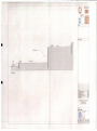
1
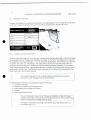
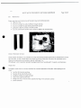
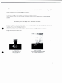
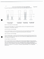
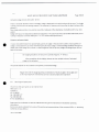
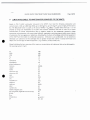
SCHEDULE
(Rule 3(1))
FORM A
THE CERTIFICATE OF ENVIRONMENTAL CLEARANCE RULES 2001
APPLICATION FOR A CERTIFICATE OF ENVIRONMENTAL CLEARANCE
This form must be completed in triplicate for any proposed activity identified in the
Schedule of the Certificate of Environmental Clearance (Designated Activities) Order. 2001.
Essential additional information such as plans, maps, diagrams, photographs or text may
be included In the application as an appropriately referenced attachment.
nent Authority.
To: The Envirot mita
1/We hereby p I o a ! ificat• Environmental Clearance (CEC).
Signed
/
Applicant/Applica
.
. .t/A. •
l.
) VC•11
kA‘SOE1S
(PRINT NAME)
ttoniey
p___17w
91d7
Signed
Aii
Y
Corporate Secretary
(PRINT NAME)
URBA Zjr t 'MN,11191i RPORATION
OF 5. rn AD AND TOBAGO LIMITED
Date
38-40 Sackville Street, Port of Spain.
•
0-6-/Cri 1 ?4112
FOR OFFICIAL USE ONLY
b1) .P? l7
Application Received
Ref. No.
......
Received by:
(Date)
(Signature)
z v1) ID
C E1C 2
Acknowledgment Sent
(Date)
Category of intended activity:
(please tick appropriate box)
(i) New 1:=1
(ii )
61
Modification
(iii) Abandonment/ Deconunissioning
PROJECT CLASSIFICATION
Activity
Definition
Application requires CEC: Y O
N D
LMA CEC 1
Application requires EIA: Y D
N
CERTIFICATE OF ENVIRONMENTAL CLEARANCE
APPLICATION FORM
A. GENERAL INFORMATION
1. Name of applicant The Urban Development Corporation Of Trinidad and Tobago (
UDeCOTI')
2. Postal Address
31 Sackville Street. Port of Spain
Electronic mailing address (e-mail address):
rogerrngudecott.com
3. Telephone no. 868-624-7469
4. Fax No. 868-623 0864
5. Location of proposed activity:
(a) District/Village
Moruga Village in Moruga
(b) Street (Name and Lot or LP No.)
1.A.A,21\2_
5 wi
6. Do you own the property on which the activity is intended to be carried out?
Yri NE)
If Yes, please attach certified copies of Proof of ownership.
II No. what is the nature of your interest in this property? Please attach supporting
documents. justifying your claim (e.g. lease).
Construction of a Police Station.
7. Names and addresses of adjoining property owners:
8. (a) Previous Application for CEC for this site?
(b) If yes. Reference No of most recent application
2
Y
❑
NE]
1.2)-1
9. Activity for which CEC required (state the activity and definition categories under which you
are applying -refer to CliC Order) as well as the purpose of the project.
Activity Z Activity #08
Definition Z C- The clearing, excavation, grading or land filling of any area with a gradient of
1:4 or more.
Purpose: To construct and operate a security (police) station for the Ministry of National Security
of Trinidad and Tobago on 1,704 square meters of land. The building will contain approximately
834 square meters of office and dormitory space.
10. Site Description (physical setting of the proposal, both developed and undeveloped areas)
Give an outline description of the physical features of the site to include information on:
(a) Topography and gradient i.e. generally flat 0 rolling/undulating terrain 0 or hilly
(b) Arc there any springs or aquifers in or adjacent to the site? YD N
(c) Are there any rivers, streams or drainage within or adjacent to the project site? YO NZ
(d) Arc there any ponds, reservoirs or wetland areas within or contiguous to the project site?
Y0 N
(e) What is the predominant soil type? Clay based Z Sand
Ej Loam 0 Alluvial 0
(f) Is the project located within 5km from the coast Z or further inland 0?
(g) Present site land use: Residential
Industrial
Forestry 0
n
n Agricultural 0 Commercial (0
11. Estimated project capital (TT dollars)
$10 million ( Ten million Trinidad and Tobago Dollars)
3
B. DESCRIPTION OF INTENDED ACTIVITY
12. Description of the Intended Activity, which must include information on:
(a) Total area intended for the activity (ha or m 2) :1704.6_ _m2
(b) Percentage of the total surface area allocated to covered space and paved areas 74 %
approximately 28 cub metres/day
(c) Potable water consumption rate (m3/day)
(d) Process water consumption rate (m3 /day) _NONE
(c) Project's intended operating capacity (metric tons per annum)__NOT Applicable_
(f) Production output rate, if different from above (metric tons per annum•) _ NOT Applicable_
(g) Intended commencement date
26/06/2010.
Site Preparation and Construction Phase
13. Does the project site require major earthworks such as clearing Z cutting Z excavation
blasting
dredging ❑?
grading
ri
If yes. state the method of disposal (and disposal site) of material generated as a result .
Excavated soil would be hauled away by truck to approved disposal sites and managed to
prevent the runoff to waterways. All truck hauling would be done during off peak hours.
(a) Does the site require filling ❑ reclamation ❑ coastline stabilisation/ alteration ❑ ? NO
If yes, state the source and quantity (metric tons) of material required.
(b) Would the project require major waterworks such as abstraction ❑ diversion of water
courses ❑ creation of standing water bodies ❑? NO
If yes, give an estimate of the volume of water to be impounded (m3) or the rate of abstraction
(m3/day) and the source of this water
4
(c) Would the site require infrastructure and utility development:
access roads and/or bridges ❑ power generating or transmission facilities
telecommunications Z installation or modification of a drainage system
sewage system®?
Ilyes. give details:
A waste water treatment plant will be installed on site, as per attachment 1
The drainage of the building will be directed to the road drainage on Moruga Road
14. Will the project require relocation of people ❑ houses ❑ facilities Z from the site?
If yes, give details: Actual police station will be relocated during the construction of the
building .
15. What percentage of the intended project area would be cleared of vegetation?
NONE
16. State mitigation measures for adverse impacts resulting during site preparation and
the construction phase.
The significant construction related impacts are expected to be the spoils disposal. A
cleaning of the road will be organize to ensure that the access to the site remain cleaned.
Operational Phase
17. State the required raw/input materials and the quantities/volumes (kg or metric tons/m3) to be
kept in stock for the project as well as their respective rates of consumption (kg or metric
tons per day/m1 per day). NONE
(a) Would the activity require any ancillary process related chemicals (e.g. catalysts, pesticides)?
NO
If yes. state the quantity (kg or metric tonnes/ m3) and rate of consumption.
(b) State the linal products to be derived and the rate of production (metric tons/m3 per year)
NONE.
(c) State any intermediate products resulting from this activity indicating the rate of production
(metric tons/m3 per year) and their fate. NONE
5
(d) State the rate of production (metric tons per year) and method of disposal of domestic solid
waste generated during the operational phase.
Following the report on the regional evaluation of municipal solid waste management services
in Latin America and the Caribbean the average pollution is 2.20 kg/day it will be an average of
30-50 kg/day.
(e) List, characterise and quantify (metric tons per year) process related solid waste. State the
method(s) and location intended for their disposal.
Rubbish to he dumped at the Forres Park land fill.
(0 Provide respective estimates for the rate of generation (m3per day) of domestic wastewater
and sewage. State the respective treatment methods intended for domestic wastewater and
sewage as well as their ultimate effluent points.
Estimate Daily I )omestic water consumption will be 1560 gallons, estimate waste water
production will he the same. The wastewater will be managed by a waster water treatment
plant.
(g) State the source and process water consumption rate (m3 per day)
All water service would be supplied by WASA and installations shall be in accordance with the
requirements of the utility. WASA. ale waste water will conform to the EMA water pollution
management program.
(h) Would the activity discharge process related liquid effluent? YZNO
If yes, state the source, composition, discharge rate (m3 per day) and the ultimate effluent points.
The estimate quantity will be 1560 gallons per day. The composition will follow the
recommendation of the EMA as per table enclosed "Table2 Maximum Permissible level or
condition water pollutants discharged into the environment"
(i) Would this activity utilise any hazardous (i.e. toxic, flammable, explosive, radioactive etc.)
substances? Y ❑ N IS]
If yes, provide a listing of the substances and the quantities to be used or stored.
6
18. Would the project require storage of input and/or waste material on site? YD N
yes, give estimates of the quantities (kg or metric tons) for the storage of:
Waste_
Input material
(a) Describe briefly the facilities allocated for this purpose
19. Indicate the mode(s) of transport intended for materials and equipment necessary
for the operational phase.
Passenger vehicles and tractor trucks.
20. Will the activity generate air emissions (i.e. particulate emissions such as dust or pollutant
Y❑ N
gaseous emissions) during the operational phases?
If yes. describe types and sources and provide an estimated emission rate or loading
21. Will the activity routinely produce odours (i.e. for more than 1 hour per day)? VD N
22. Will the activity generate significant levels of noise (i.e. for more than 1 hour per day•at
levels exceeding 60 dB) during its operational phase? YOND
23. Will the project have adverse effects on the aesthetics of the area where it is located (i.e.
result in radical changes of the landscape. such as scarring/mass vegetation removal)?
YE NZ
24. State mitigation measures for adverse impacts resulting during the operational phase.
No significant adverse impacts are anticipated.
24. State the expected lifespan of this activity:
Duration of the construction site will be 9 months
C. CONFIDENTIALITY
26. (a) 1)o you consider any information provided here to be a trade secret or other
confidential business information and that such information be omitted from the Register?
Y❑
7
(b) (ike details
27. Other relevant information
•
28. Please list any attachments included in the application
Attachment I: Waste Water Treatment Plant WASA Submission
Attachment 2: Project Description and Drawings
•
ATTACHMENT 1
•
WASTE WATER TREATMENT PLANT
WASA SUBMISSION
•
WASTE WATER TREATMENT PLANT WASA SUBMISSION
1 INTRODUCTION:
2
2 EMA REQUIREMENTS:
3
3 PLANS:
4
4 PICTURES:
5
S LOCATIONS:
6
. 6 OPERATING MANUAL
•
Page 1/28
9
9
6.1
Supplier data
6.2
Introduction
9
6.3
Principles of safe use of the plant
9
6.4
Identification
6.5
Installation and start-up of the plant
II
6.6
Maintenance
14
6.7
Servicing and
of the plant
spare parts
11
19
7 INSTALLATION OF WASTE WATER TREATMENT PLANT
20
7.1
Introduction:
20
7.2
Parts:
20
7.3
Description of the process
21
7.4
Control of the mechanical equipment
22
7.5
Putting of the WWTP into operation
23
7.6
Putting of the wwrp out of operation
23
7.7
Sludge removal
23„
7.8
Sludge removal before putting of the WWTP out of service
24
7.9
Operator's activities
24
7.10
Health and safety
26
S LIMITS APPLICABLE TO WASTEWATER CONVEYED TO THE WWTP:
28
WASTE WATER TREATMENT PLANT WASA SUBMISSION
Page 2/28
1 INTRODUCTION:
The waste water will be discharged by gravity through pipes and will be collected to a local waste
water treatment plant (WWTP) to be installed within the compound. Outlet water to be discharged
to storm water drainage system
•
Waste Water Treatment Plant discharge shall be in accordance with the Environmental Management
Authority Requirements.
Page 3/28
WASTE WATER TREATMENT PLANT WASA SUBMISSION
2 EMA REQUIREMENTS:
Table 2. MAXIMUM PERMISSIBLE LEVEL OR CONDITION OF WATER
POLLUTANTS DISC HARGED INTO THE ENVIRONMENT
No.
NN'ater Pollutants
Parameters or Substances
Inland
Surface
Water
Level or Condition
Environmentally
Marine
Coastal
Sensitive Areas
Nearshore Offshore
°Groundwater
6-0
30
40
6-9
50
4f
6-9
100
NIAA
6-9
10
20
50
'50
150
10
1$
250
200
100
60
15
No discharge
10
.
1
250
1
1.
10
5
1
NIAA
1
0.1
10
c
1
NIAA
_
01
0.31
0.1
0.2
NLAA
0.2
005
•
S
0
10
11
12
7. emperaute
Hydr gen :an .pHi
Five
cla.'
Ril
al Oxygen
Den:3'01E0D- at 20'i:
C1.etr.ical Oxylen Demand CODS
Tz.ial S',...iperided Solich . -2SS I
Tnal 011 and Cnita.e . TO&Cri oti 1iHexane EXITI:•;11it :Amen:11.1;Es/
Anur..5noca: N1115zen .:C7 NH;-.2:
:l p::':,.:
.7.
Stilpi:ide a i.1-1.21.1
C01..-.:Ide 1., c :1
-2 :•Tal Re..id...1 C:..:ot..ile . as C 1.
DI ,..-..h•ed Hex:v.-ale...A ( lit onatan
13
14
15
7, °l.1' Chromium . C r!
Ditss:51ved Iron 1 Fe:
Hydrocarbons
7:51a1 Pertolettin
05
5
25
0.5
35
40
0.5
3.5
SO
0.1
10
No discharge
16
Ni
7....tal Nitkel I.
7 .:•tal ( .5..,pet • C it
:5111 Zit:: • Z.....
.2.5tal Ar .:11..: . A.,
7. n1 C 1.1r.liwit • Ci
7. ral :.let zun. .Hin
1%,ial Lead .pt ,
7 z.tal C vanide • as CN''
Thenoir: C onr,s.oultd'i :as phenol:
Radioir......,.
T. :.xi,Ir.
Fae:.'ai C o:lio: lib
Solid W.Ii.te
:: :
::
: 1
,
::. 01
05
17. f
-•
01
05
05
01
05
001
0.1
001
I
_
.„
4
6
r
1S
19
20
21
•s
-23
24
26
'7
'
OA
0I
001
0 01
001
0 005
1
C,.1
01
0.05
1
, ..
Nl...-1_4.
NATE
4:,0
NSD
0.1
0.5
NLA...A.
NATE
400
NSD
0.1
0.5
NIAA
NATE
400
NW
001
0.1
NIAA
NATE
100
NSD
are '.n:11:11ignal.
bare 'mg L. except fx ten:perm:re tcc .. pH ipH tuts; faecal colifomn count$ per 100m1).
radiaavinr. (3.„ L last
taw;
NIAA - nz, .s.crea:6 abo.'e aintxett
NATE Toxic effe:1-,
Page 4/28
WASTE WATER TREATMENT PLANT WASA SUBMISSION
3 PLANS:
L200
0
ZOO
2799
4
I
I
1
A
WASTE WATER TREATMENT PLANT WASA SUBMISSION
4
PICTURES:
•
Page 5/28
WASTE WATER TREATMENT PLANT WASA SUBMISSION
5 LOCATIONS:
As per Attached drawings
•
•
Page 6/28
WASTE WATER TREATMENT PLANT WASA SUBMISSION
VI
Page 7/28
Calculation note:
The EMA standards are equivalent to international standard. The VARIO COMP system was designed to treat
the water following the international requirement. The goal of this calculation is to demonstrate that we are
strictly below the capacity of the water treatment tank meaning that the final effluent will be correctly treated.
Affluents data:
Volume :
Q24 = 7.5m3/d
Qd = 0.46m3/h
Qh = 3.08m3/h = 0.861/s
•
Weight :
Waste water pollutants
BOD : 3.0 kg/d
COD : 6.0 kg/d
2.75 kg/d
SS :
N tot : 0.55 kg/d
P tot : 0.125 kg/d
Primary sedimentation and desludging
Mirror surface
A = 2.96m2
Superficial charge
qv = 0.165 1.0m/h
qm = 1.045 5.0 m/h
Hydraulic journey time :
Vps = 4.02m3
Td= 8..7 2 2.0 h
Th = 1.3 .2 0.5 h
Sludge production:
PK = 75l/d
PK = 2.25m3/month
Activation tank
Because the journey is longer than 2 hours in the sedimentation compartment, the concentration decreased to
40g/EH/d
BX = 0.10kg/kg.d
Clarifier tank
Reduction of the hydraulic charge due to the size of the accumulation tank.
q= 0.45 5 1.2 m/h
Reduction of the pollution due to the size of the accumulation tank.
q = 1.8 5 Skg/m2,h
004.01,41.•
WASTE WATER TREATMENT PLANT WASA SUBMISSION
VII
Page 8/28
Chlorination:
In order to achieve the 400mg of faecal coliforms per liters of water. The final effluent will be mixed
in a concrete tank with chloride. We use an automatic pump system in order to measure the chloride
that we use instead of tabs.
The chlorination pump with a concentration of NaOCI between 180 gr/ m3 and 300 gr/ m3 will give us
the following pollutions:
Chloride
schedule).
Total residual Chloride
•
< 180mg/ liter (the threshold is 250 mg/liters in the EMA first
< 0.2 (As asked in the EMA first schedule).
The rejecting pollutants are not above the threshold of the EMA first schedule and so are not
considered as pollutants.
The chlorination has been chosen instead of the UV filtration, because there is less maintenance cost,
and it is more solid and reliable for long use.
•
WASTE WATER TREATMENT PLANT WASA SUBMISSION
6
Page 9/28
OPERATING MANUAL
This user's manual includes important instructions and safety precautions. You are kindly asked to read the
manual carefully before starting using the plant.
6.1
•
Supplier data
Technical office:
ASIO, spot. s r.o.
POB 56, Tufanka 1
627 00 Brno — Slatina
Valid from: 1. 6.2006
Tel.: 548 428 111
Web: http://www.asio.cz
E-mail: asio@asiacz
6.2
Introduction
The wastewater treatment plant AS-VARIOcomp N (hereunder the plant or WWTP) is a product designed and
manufactured to a standard corresponding to the state-of-the-art scientific knowledge and technology.
This operating manual should allow you to become thoroughly familiar with the wastewater treatment plant
and to ensure its safe and trouble-free operation.
The safe and trouble-free operation of the plant is based on following of all instructions and precautions
presented in this manual. Damage caused by inappropriate handling, improper use or wrong attendance
during the guarantee period cannot result in claims for a charge-free guarantee repair.
6.3 Principles of safe use of the plant
Operation and maintenance of the plant may be executed by people more than 18 years old, who are
physically as well as mentally competence to exercise such work and who have been duly familiarized with the
manual.
Installation of the plant may only be performed by people and companies with corresponding experience and •
qualifications to perform construction work and installation of technical facilities, which are familiar with
design and installation documentation provided by producer.
Page 10/28
WASTE WATER TREATMENT PLANT WASA SUBMISSION
Service work may only be performed by the company ASIO spol. s.r.o. or a company trained and authorized by
Asio (hereunder the authorised representative).
Intervention in the electric parts of the blowers may only be performed by people with
corresponding electro-technical qualifications and only in a scope defined in the blower
operating instructions.
Wastewater at the plant may be a source of various diseases. Therefore, you should prevent from a direct
contact with water and sludge at the plant. When performing work requiring opening of the plant it is
necessary to use suitable work clothes, rubber gloves and follow carefully the general sanitary principles.
Do not drink, eat or smoke when doing work before opening the plant.
Tools and aids that get in touch with wastewater or sludge must be carefully washed
with water after use. The used work clothes, gloves, tools and aids must be stored in a
proper place.
Wash your hands carefully with soap and warm water, as a minimum, during work.
The plant tank is an underground structure with a risk of falling in when the lid is removed.
Be particularly careful when the plant is open. Do not leave the plant open unattended.
The closed lid should always be locked.
In case of extraordinary events it is necessary to follow generally applicable safety precautions and regulations
related to entering into underground structures.
In case of need, there will be warnings against any other dangers mentioned in the specific parts of this
manual.
WASTE WATER TREATMENT PLANT WASA SUBMISSION
6.4
Page 11/28
Identification of the plant
The plant is provided with a production label located on the upper edge on the internal part of the inlet shaft
to the inlet chamber (the WWTP primary part). The label is accessible when the plant lid is open.
Cistirna odpadnich vod
Jmenovda velitoal CO
Ma 11 ?or moment) mnntstr
x911351(
17I
Out,
NSA
Norma
CHSIK
NI
1.1114on
ASIO, spol. s r.o., POB 56,
Tukanka 1, 627 00 BRNO, CZ
Te1.:548210012
6.5
E
II
Installation and start-up of the plant
The plant should be handed over to the user after a professional installation performed in line with the design
documentation and the "Designing and installation instructions for the WWTP AS-VARIOcomp N". Following
the installation, the company ASIO spol. s r.o. or its authorized representative will commission the plant and
will hand it over to the user. The phasing in will include training of the future operators (that is why the
presence of the future operators is necessary during the hand over procedure, eventually it is necessary to
render training additionally after ordering against payment). Phasing in and training of the operators will be
documented in writing in the " Installation and hand-over protocol". This document is also required by the
Water Authority for the final plant approval.
Do not operate the plant if it has not been phased in and the operators trained as
documented in the "Installation and hand-over protocol"
The following documentation will be handed over along with the plant:
• certificate of warranty
• protocol on the plant tank water tightness test
• draft operating rules and operation manual
• log-book
• blower operating instructions
You are kindly asked to check whether the type and production number of the plant
complies with the data in the provided technical documentation and the proposed type
of the plant according to the design documentation.
If the plant is not phased in according to the manner, do not operate the plant and
contact ASIO, spot. s r.o..
WASTE WATER TREATMENT PLANT WASA SUBMISSION
Page 12/28
After settling and concreting of the plant tank, the plant tank is filled (in all spaces ) with water up to the
maximal level. The electrical switchboard, delivered together with the plant, is fixed on the wall and
connected with using a feeding cable, another cable is used for interconnection of the plant and the blower.
The blower delivered in a plastic box is placed in a vicinity of the plant tank (reducing of pressure losses in the
piping). The cable passage to the blower casing must be waterproof. Electrical connection inside the
switchboard and blower terminal will be executed by serviceman during putting the plant into operation. The
air pipe connection between the blower and air distributor, positioned in the plant tank above the water level
in the final sedimentation tank, will be also be executed by serviceman during putting the plant into operation
(if not agreed otherwise). This connecting pipes must laid In a shortest possible distance, without sharp bents,
the pipe profiles can differ on the basis of the delivered blower type and size (mostly often 3/4") and the
profiles must not be reduced to smaller diameters.
In case that electrical device (blower) is connected to the three-phase system, it is necessary to check the
proper direction of the motor revolution (In case of a wrong adjustment, the blower is working as a vacuum
pump and when the water is sucked in —the.blower is destroyed —this defect is not covered by the guarantee).
There is no standard protection against the wrong phasing in the switchboard so it is necessary, when any of
repair or work in the electrical system, to recheck the proper motor revolutions direction-which must be
executed at a loosened screw connection at the delivery conduit located behind the blower.
Following activities:
• putting the blower into operation (activation begins fine bubbles aeration), timer setting (blower
operating time)
• visual check of the piping completion and their tightness
• air inlet valves adjustment for the input to the mammoth pumps for sludge recirculation and the '
outlet of cleared water from the sedimentation tank
• air inlet to the mammoth pump for excess sludge pumping out to be checked and the valve should be
kept closed.
• To demonstrate plant function and operation to the person to operate the plant — attendants'
training
• to fill in the assembly protocol/handing over protocol, certificate of warranty, and record the putting
of the plant into operation to the log-book.
Sewage wastewater may be conveyed to the plant from the building for which the plan is designed. The design
of the plant and its technical parameters are dimensioned for treatment of wastewater corresponding to the
composition and character of sewage wastewater according to CSN 756402 „Wastewater treatment plants for
up to 500 PE".
Potential changes in the use of the plant must be consulted with the author of the original design, authorized
service centre or the company ASIO spol. s r.o.
0
Waste in the building to which the plant is connected must not contain any substances
which deteriorate or even disable life and reproduction of microorganisms that the
function of the biological plant is based on (see the relevant chapter ).
Discharging of the following substances is forbidden:
Poisons and toxic substances,
Paints, dissolving agents and chemical sprays
undiluted acids and bases
other chemicals, such as developing agent, fixatives etc.
WASTE WATER TREATMENT PLANT WASA SUBMISSION
Page 13/28
The biological wastewater treatment process in the plant is basically identical with the self-purification process
in the nature. This indicates a certain "vulnerability" of the plant related to inadequate and incautious
behaviour, above all in the field of use and discharging of chemical agents.
BEWARE OF disinfecting agents !
disinfecting agents for sanitary hygiene must be used with utmost care. They kill
viruses and bacteria in the household but they also reliable kill bacteria in the plant
which ensure the treatment process.
•
BEWARE OF inadequately frequent laundry washing!
The quality of the treatment process in the plant is adversely affected by inadequately
high quantities of detergents and tensides during laundry washing (several washing
cycles in a series in a short time interval). Distribute the „big laundry" in time over
several days
BEWARE OF oils and grease !
Besides chemical agents, animal grease and vegetable oils in high quantities are
dangerous to proper functioning of the plant. Their decomposing strongly acidifies
wastewater and thus creates adverse environment for the plant biology.
BEWARE OF discharging of water from a pool !
Discharging of high quantities of clean water via the plant , e.g. from a pool or rain
water storage usually results washing of microorganisms out of the plant which disables
further operation of the plant. The pool water has adverse effects due to its chemical
composition (chlorinating and stabilizing agents).
•
OPIPMVI •
WASTE WATER TREATMENT PLANT WASA SUBMISSION
Page 14/28
6.6 Maintenance
Proper operation and maintenance of the plant requires the following tools:
•
•
•
•
•
ladle on a stick
brush on a handle for wall and effluent trough cleaning
brush on a handle for pipe cleaning (mammoth pump)
graduated 1000 ml cylinder or Imhoff cylinder
3 pcs of polyethylene bottles with a volume of 1000 ml for sample taking
Check of the blower function
Check whether the blower is on, whether the noise level did not increase significantly or whether there are any
signs of defect. In case of doubt about the proper functioning, follow the instructions for the blower use or
contract an authorized service centre or directly ASIO spol. s r.o.
If the blower is not in operation outside the programmed time of switching off- the plant is not functional.
•
Visual check
The regular visual check is a primary condition for successful operation of the plant. After opening the lid
check:
• Function of activation aerating
• Function of the mammoth pumps
• Condition of effluent trough and pipe
•
Level in the sedimentation tank
• Sludge colouring in the activation, possibly foaming on the activation surface
• Overall condition
WASTE WATER TREATMENT PLANT WASA SUBMISSION
Page 15/28
Function of activation aeration
At the bottom of the activation tank there are diffusers -aeration elements (their number is according to the
size of the WWTP), into which the pressure air from the blower is driven (through the air distributor). The
membrane of aeration element is designed, so that the holes are covered when the air Input in closed and thus
protects water infiltration to the bearing cylinder of aerator.
The membrane pores create small air bubbles, which are equally dispersed in the whole activation tank
during the proper function.
If it is found during the visual check that in one place of the activation tank the mixture water-sludge is
"boiling" (there is no equal aeration on the all activation surface level), it means that there is a membrane
damage or an inlet hose is broken. In this case, the aeration element must be removed and the defect must
be repaired. For the better manipulation, the aeration element is equipped with the guiding rope in the one
side and on the other side the input hose is use for manipulation.
Foam is created on the tank level, its colour shows us the proper operation of the activation process.
If the foam is white, it indicates insufficient mass load of the plant (wastewater is „hungry"), there is no active
sludge in the activation, during new putting the plant into operation the white foam appears normally (a
reached height of tenths of cm) and gradually changes its colour to the brown one with higher „density", after
approx. 3 - 4 weeks there is brown consistent foam with a thickness of approx. 100 mm on the surface.
The white „opalized" foam probably signalizes a higher content of detergents in the inflow waste water (there
are presented in cleaning agents).
The air input from air distributor to the aerator is led through the ball valve and drain valve, which removes•
water that penetrated to the aerator from the tank or which condensated from the inlet air. Water presence
in the aerator decreases its performance and therefore it is necessary to dewater aeration system manually
during the regular system checks.
•
WASTE WATER TREATMENT PLANT WASA SUBMISSION
Page 16/28
Mammoth pumps function:
There are mammoth pumps installed in the plant, for extracting of return sludge from the sedimentation tank
back to the activation and, for securing of circulation of the excess sludge from the activation to the sludge
space. Mammoth pump of return sludge is designed so that to separate air used for the sludge liquor pumping
and use its overpressure again as a drive of further mammoth pump for controlled discharge of pre-treated
water from the plant.
Mammoth pump for return sludge — sludge liquor stock inlet to the mammoth pump tube is the air trap, to
which the air is led close on the sedimentation tank bottom with use of perforated pipe. The mammoth pump
pipes must be airtight and its inlet point at the activation tank must be under water level in depth which Is
bigger, than depth of air inlet to the mammoth pump for controlled discharge of the pre-treated water from
the plant. Controlling of this mammoth pump is manual with hand valve which transports air under the
mammoth pump trap.
The pipe of the mammoth pump for return sludge is equipped in the upper part with device for catching and
dewatering of used air and a its overpressure is used again as a drive of further mammoth pump for
controlled discharge of pre-treated water from plant sedimentation tank.
Mammoth pump for excess sludge— in case of increased sludge quantity in system activation-sedimentation
tank, this pump secures the sludge discharging to the sludge tank. The mammoth pump control is manual by
means of hand valve, which feed air to the mammoth pump piping, pump switching on and off depends on the
result of 30 min of sedimentation test. .
In case of some suspicion that there is faulty function of some mammoth pump, it is necessary to adjust pump
eventually to render cleaning with use of pressure water.
Check and extraction of excess sludge:
•
In order to ensure proper operation of the plant it is necessary to provide optimum amount of activated sludge
in the activation part of the plant. Activated sludge consists of microorganisms that "feed" on impurities
contained in wastewater which results in the treatment process. As their gradually proliferate, it is necessary
to maintain their optimum volume in the activation. For these reasons a part of the microorganisms must be
extracted from the activation. The extraction is performed by discharging of the mixture of water and sludge
from the activation zone using the mammoth pump of excess sludge to the sludge zone.
WASTE WATER TREATMENT PLANT WASA SUBMISSION
Page 17/28
Check of the volume of activated sludge in the system:
The volume of sludge in the activation zone must be checked as follows:
Using a ladle on a stick take water from the activation and pour it into Imhoff cone of 1-liter graduated
cylinder.
When taking water and sludge mixture, the bower must be on.
•
•
The filled Imhoff cone (or graduated cylinder), usually a 1-liter cylinder with water and sludge must be put on a
levelled surface and let settle down for 30 min.
Watch at what height there is a distinct border between water and sludge settled on the bottom
Sludge monitoring in an Imhoff cone:
Imhoff cone Freshly taken mixture of
water and sludge from
activatioN
atter 30-min settling
distinct border between water and sludge
(e g low sludge concentration min.)
WASTE WATER TREATMENT PLANT WASA SUBMISSION
The results of observation will provide information about the activated sludge concentration:
Page 18/28
1/2
113
Optimum concentration
of activated sludge
Low concentration of
activated sludge
High concentration
of activted sludge
No activated sludge
has been formed
Optimum concentration of activated sludge:
The volume of settled sludge is 1/3 - 1/2 of the total taken volume, which means that the volume of
microorganisms in the activation is optimum..
Low concentration of activated sludge:
Volume of settled sludge is less than 1/3 of the total volume, which means that there are no enough
microorganisms in the activation and no sludge needs to be extracted from the activation.
High concentration of activated sludge:
Volume of settled sludge is us more than 1/2 of the total volume, which means that there is excess of micro
organisms in the activation and the sludge volume must be reduced by de-sludging using mammoth pump of
excess sludge into the sludge zone.
Activated sludge has not been formed:
There is no border between water and sludge, which means that activated sludge has not been formed yet
(thus is possible during the phasing in of the WVVTP for a period of approx. 8 weeks), or disappeared for some
reason (e.g. single discharging of a greater volume of detergents into the sewerage to which the plant is
connected). In all cases wait approx. a week whether the situation starts improving (the concentration will be
progressively increasing). If it is not the case, it is necessary to contact ASIO spot. s.r.o. or its authorized
representative.
WASTE WATER TREATMENT PLANT WASA SUBMISSION
Page 19/28
Activated sludge did not settle after 30 min.:
There is no border between water and sludge, sludge is dispersed in the whole volume of the cone. The sludge
is young, too fine with low settling capacity. This situation will improve with time after the plant has been fully
phased in.
Poor sludge sedimentation may also be caused by inadequate inflow loading by unsuitable waters ( e.g. toxic
water).
Sludge settling can be adjusted by additional coagulation. This case must always be handled individually and it
is always necessary to contact ASIO spol. s.r.o. or its authorised representative.
•
Extraction of excess sludge
In case, that sedimentation test proved high quantity of sludge in the activation system, excess quantity of
sludge is extracted with use of the mammoth pump of excess sludge. Extracted sludge outflows through the
outlet pipe to the sludge zone, where it is stored together with the primary sludge and sludge liquor returns
back to activation.
De-sludging should be carried out for a period of approx. 4 — 8 hours
After completion of de-sludging, always test the residual volume of activated
sludge in the activation
The period depends on the condition and quantity of activated sludge .
Regular check of the sludge quantity and extraction of excess sludge in the sludge zone
is the most important maintenance activity to secure proper plant operation.
•
6.7 Servicing and spare parts
Any service and spare parts can be ordered from:
ASIO, spol. s r.o.
Tufanka 1
627 00 BRNO
tel.: 548 428 111"
fax: 548 428 100
E-mail: [email protected]
Spare parts for the blower can also be ordered according to the instructions in the blower operating
instructions.
Service can also be ordered from some of the authorized representatives of the company ASIO s.r.o. according
to the list on www.ASlO.cz.
Brno 20 6 2006
WASTE WATER TREATMENT PLANT WASA SUBMISSION
7
Page 20/28
INSTALLATION OF WASTE WATER TREATMENT PLANT
7.1
Introduction:
These operating instructions serve as a manual for the operation of the wastewater treatment plant. The
instructions do not deal with professional control of the WWTP operation by a person authorised to conduct
these activities.
•
7.2
Parts:
Tank:
The external side of the WWTP tanks is made of wall polypropylene elements SP 80. All internal partition walls
and built-in parts are made of plastic materials, polypropylene (SP 80, KD 20 or Polypropylene). The tanks are
encased in concrete. If they are designed as self-supporting, they must be internally supported.
When installing the tank on site it is necessary to consider the local conditions and, if needed, make further
static securing. The tank is not sized to potential additional pressure loading by passing truck wheels,
foundations etc.
Mechanical — technological equipment:
The mechanical-technological equipment of the WWTP consists of a source of pressurised air — blower, finebubble aeration system, el. switchboard and a system of mammoth pumps extracting excess and return
sludge.
Wiring system
•
Main feeding cable leading to the WWTP switchboard:
CYKY 5C x 4 mm=
The blower is automatically controlled using a time-switch installed at the switchboard. Based on the actual
situation and characteristics of the given type wastewater and the WWTP operation it is possible to adjust the
setting so as to make it correspond to the specific type of wastewater. This means that the duration and
frequency of aerating the aeration tanks can be set and thus the volume of return sludge can be adjusted
within the internal recirculation. It is also possible to set the volume of excess sludge withdrawn to the sludge
tank.
Blowers
Blowers ensuring oxygen supply (type, power input):
according size of wastewater treatment plants.
WASTE WATER TREATMENT PLANT WASA SUBMISSION
Page 21/28
7.3 Description of the process
Mechanical treatment:
The mechanical treatment stage at the WVVTP includes a primary sedimentation tank where suspended solids
are separated by gravity from the wastewater. One part is separated by sedimentation, another part is
separated by flotation and settles at the bottom. Mechanically treated water is conveyed over a scum board to
the biological stage.
Biological treatment:
The biological stage of the WWTP includes an activation tank with a low sludge loading enabling removal of
carbonaceous pollution and nitrification. This tank is equipped with fine-bubble aeration elements ASEKO
ensuring transfer of the required quantity of oxygen. This pressurised air is supplied by a blower, which also
supplies air to the mammoth pumps in the secondary tanks in order to enable return sludge recirculation and
removal of excess sludge.
Secondary tank:
A mixture of treated water and activated sludge is conveyed by gravity to the secondary tank. The secondary
sludge is designed to separate and partially thicken biological sludge originating in the biological wastewater
treatment process and to reduce as much as possible the concentrations of suspended solids in the effluent.
The mammoth pumps in the secondary tank ensure extraction of excess sludge to the sludge tank. The
second pump ensures internal sludge recirculation between the secondary tank and the activation tank.
Sludge tank:
The sludge tank is integrated in a structure which also houses the primary tank and it is used to store excess
sludge originating from the WWTP operation along with primary sludge. The sludge is anaerobically stabilized.
60+1111.• •
WASTE WATER TREATMENT PLANT WASA SUBMISSION
Page 22/28
7.4 Control of the mechanical equipment
The mechanical equipment is controlled from the switch board. The drawing showing the controlling and
signaling switch board elements can be found in the switch board. Controlling of the WWTP operation consists
in switching on (and off) of the relevant circuit breakers of the blower. The interval of the blower operation is
controlled using an electronic time switch.
Oxygen supply from the blower is ensured by an air distributor with a manual control of the individual oxygen
inlets to the equipment.
•
The electronic time switch is set when commissioning the WWTP or during a service inspection carried out by
the supplier or the authorised service organisation to a standard mode, which can be adjusted based on the
specific operating conditions by changing the time intervals. A separate detailed description of the electronic
time switch is presented in the enclosed manual. The supplier or the authorised service organisation has
trained the operators so that they are able to adjust the time intervals in the wastewater treatment process.
The instruction to change the time mode for the individual pieces of equipment will be issued by a professional
authorised to operate the WWTP, or the supplier of the WWTP on the basis of relevant observations and
laboratory tests.
If necessary, the blower run control may be switched over from the automatic mode to manual mode. For this
purpose, the digital time switch is equipped with a key. The manual mode can be switched over to the
automatic mode using the same key. The blower is switched off by means of the relevant circuit breakers. .
WARNING !
During operation, the WWTP must be operated in the automatic mode controlled by the time switch, i.e. the
operation of the electronic time switch must not be blocked.
•
In case the red light failure signalling is on, such failure signals switching off of the blower motor circuit
breaker. The operator must restart the circuit breaker. In case the circuit breaker switches off again, this
signals damaging of the bower.
WASTE WATER TREATMENT PLANT WASA SUBMISSION
7.5
Page 23/28
Putting of the WWTP into operation
The covers are opened manually. The covers are secured against unauthorized opening by a pad lock. After
unlocking the pad lock, the cover can be opened around hinges using a handle. The opened cover must be
secured in this position against spontaneous closing using a strutting bar (part of each cover).
WARNING
The opened cover of the WWTP must also be safeguarded by the strutting bar !
When putting the plant into operation (when the WWTP is evenly filled up with water), which is carried out by
a supplier or an authorised service organisation, the WWTP is kept in permanent operation and it is possible to
start introducing wastewater. The period before the plant reaches its full treatment efficiency (provided that
the hydraulic and 80D loading is as per the design) is ca. 4 — 8 weeks or less in case activated seeding sludge is
used.
WARNING !
In order to ensure proper operation, the WWTP must be kept in permanent operation, i.e. it is not possible to
leave it disconnected beyond the absolutely necessary period, for example for repair work, cleaning etc.
7.6
Putting of the WWTP out of operation
Disconnecting of the WWTP is performed by means of circuit breakers installed in the switch board.
77
Sludge removal
Sludge is removed as necessary once the sludge storage spaces are filled up and as allowed by the possibilities
of sludge removal and disposal. It is recommended that a specialised experienced company should be engaged
and the sludge should be removed using a gully sucker. The sludge is extracted from the sludge tank as follows:
open the lid covering the sludge space, switch off the WWTP using the circuit breaker and insert carefully the
suction basket to the sludge spaces (to ca. half of the level). The gully sucker first extracts water from the
central part of the sludge tank and then discharges the water back to tank so as to mix and homogenize the
content of the sludge tank. Then the hose of the gully sucker is dropped to the bottom of the tank and all the
volume is sucked out with ca. a 200-mm layer of a mixture of water-sludge on the tank bottom. Immediately
after extracting the sludge, the WWTP must be refilled with water up to the original level. The WWTP is then
put back into operation.
WARNING !
Incautious handling of the suction basket of the gully sucker may result in cracking of the WWTP bottom or
damage to the partition walls. In such a case sludge is not extracted nether form the activation tank or from
the secondary tank !
WASTE WATER TREATMENT PLANT WASA SUBMISSION
7.8
Page 24/28
Sludge removal before putting of the WWTP out of service
When interrupting the operation of the WWTP for a longer period of time, i.e. ca. 3 months, with not pollution
inlet, i.e. inlet to the activation tank, it is necessary to extract sludge from the WWTP before its closing down.
Unlike the description in Article 4.7, the sludge must also be extracted from the activation and secondary
tanks. The WWTP is switched off before extracting sludge from the activation and the secondary tanks so that
the sludge can settle at the bottom of the activation. After ca. 3/4 hour it is possible to extract the settled
sludge front the bottom of the activation and secondary tanks by means of a gully sucker.
ATTENTION — when emptying and filling the wastewater treatment plant, i.e. its parts, it is necessary to ensure
the same wastewater level in each of the parts — DANGER OF DAMAGING THE PARTITION WALLS!!! The
maximum difference in levels is 30 cm.
7.9
Operator's activities
The WWTP does not require permanent attendance. When putting the WWTP into service, this plant operates
in the automatic mode and it is only necessary to perform such activities in regular intervals that are targeted
at checking of the WWTP operation and the treatment process parameters.
WARNING I
During any handling of the blower or other parts of the aeration system, the WWTP must be disconnected
from the power supply by means of the circuit breakers and residual current device and the WWTP must be
kept without voltage (locking of the switch board, warning plates). During any handling of the blower or
other parts of the aeration system, the WWTP must be out of operation.
•
WASTE WATER TREATMENT PLANT WASA SUBMISSION
Page 25/28
The scope and intervals of the activities are shown in the table below:
Type of activity
Visual check of the WWTP operation
Cleaning of outlet holes, connecting pipes
Extraction of floating sludge from the surface of
the secondary tank
•
Measurement of sludge level in the sludge
storage space
Sludge removal
Sample taking and ensuring of sample analyses
Interval of activities
Once a day
As required based on the result of visual check
As required based on the results of the visual
check in case of occurrence of floating sludge
(spontaneous sludge extraction)
One a month
As required or at least twice a year
As required according to the decision of the
water authority
It is necessary to check whether the outlet holes and the connecting pipes between the technical spaces are
not clogged. The space of the inlet part is accessible after removing a lid covering this space. It is also
necessary to monitor the color and the appearance of the activated sludge and whether there is no
occurrence of floating sludge on the surface of the secondary tank and extract it, if needed. It is also
necessary to check the operation of the equipment, which is light signaled on the switch board and it is also
important to check the sound of the blower when it is put into service on the switch board. When there is a
major change in the appearance or the sludge color (e.g. blackening, yellowing, etc.) it is necessary to
immediately approach a skilled operator who will make potential investigation and take samples or activated
sludge analyses in order to prevent from potential breakdown of the biological stage at the WWTP.
Cleaning of outlet holes, connecting pipes
Cleaning of the outlet holes, connecting pipes is performed using a brush and a scraper that can be supplied
together with the WWTP.
Removal of floating sludge (scum) from the surface of the secondary tank
•
Floating sludge is extracted from the surface of the secondary tank by means of a collecting strainer.
Measurement of the sludge level in the sludge storage space
The sludge level is measured by a sludge gauge. When slow submerging of the gauge a change in the
resistance is felt , which means that the border between water-sludge was reached. In this case, submerging
of the gauge represents the water level above sludge. The minimum water level above sludge at a sludge
depth of 1.0 m is 1.1 m.
Sample taking and sample analyzing
This activity must be performed on the basis of instructions set in the valid decision of the water authority. As
a standard, samples of treated wastewater are taken in the first sewerage inspection behind the wastewater
treatment plant. When operating the WWTP, above all during breakdown situations, or when putting the
plant into operation and setting of the treatment parameters, it is advisable to take samples of sludge at the
inlet of the WWTP and samples of activated sludge from the activation tank— this is performed by an
authorized and professionally skilled person.
WASTE WATER TREATMENT PLANT WASA SUBMISSION
Page 26/28
Winter operation
The operation of the WWTP, its maintenance and attendance is similar to the summer period. As a standard,
the WWTPs are installed as underground structures covered by a heat-cladded For this reason, there are no
changes in the winter operation and increases demands for attendance.
Operation and measures taken during extraordinary operating conditions:
FLOODING — in case of the risk of flooding, disconnect power supply and dismantle the blowers.
FIRE — extinguish using a foam extinguisher.
Maintenance of the blower
•
Based on the delivered type, the blower is operated and maintained according to the service conditions issued
by the blower producer , which are included in the delivered documentation.
7.10 Health and safety
- The plant can only be operated by a person more than 18 years old, physically and mentally capable of
conducting such work and familiarized with these instructions. The operation also includes activities related to
the transport, installation, putting into operation and maintenance.
- any intervention with the el. part of the WWTP can only be performed by an authorised electro-technician
with corresponding qualification set by Directive No.. 50/1978 5b.
- the operator is obliged to following the instructions prescribed in these operating Instructions and the
operating rules approved by the relevant water authority.
•
- the operator must not handle the WWTP or any of its parts unless such activities do not result from these
instructions or the operating rules.
- when performing work when direct contact with wastewater or sludge cannot be prevented from, it is
necessary to take all measures to limit the contact with wastewater and sludge and to use protective aids. If
necessary, the equipment must be sprayed by pressurized water.
- wastewater may be a source of various illnesses. Therefore it is necessary to protect oneself against direct
contact with wastewater. When performing maintenance work it is forbidden to eat, drink and smoke. After
completion of work, the operator must was his hands by soap and hot water, as a minimum.
- the operator must be vaccinates against tetanus, as a minimum.
- The WWTP must be secured against access by unauthorized persons, above all against access to the tank
covers
WASTE WATER TREATMENT PLANT WASA SUBMISSION
Page 27/28
THE OPERATORS ARE FORBIDDEN TO:
- perform work that is contrary to the directions given in these operating instructions, generally valid safety
precautions and the operating rules
- consumption of alcoholic beverages and medicines before commencement of work reduces the operator's
attention
- enter the inner spaces of the WWTP and the WWTP cover
- perform any work at the WWTP without proper securing of the lid by the strutting bar.
Personal protective aids
When operating the WWTP, the following personal protective aids must be used:
- working clothes, boots
- protective rubber gloves
Working aids
When operating the WWTP, the following working aids must be used:
- ladle with a long handle
- sludge gauge
- polyethylene bottles for samples- 1 liter - 3 pcs
- brush attached to a handle for cleaning of walls and the effluent trough
- bar with a length of 2 m
- graduated 1-liter cylinder or Imhoff cone
Note: the tolls above are not part of the delivery, they can be ordered from the supplier
.
12. SPARE PARTS AND SERVICE
Spare parts can be ordered at the supplier:
ASIO, spol. s r.o.,
Tufanka 1, P.O. BOX 56
627 00 BRNO
tel . 548 428 111
. 548 428 100
or in an authorised service centre.
WASTE WATER TREATMENT PLANT WASA SUBMISSION
Page 28/28
8 LIMITS APPLICABLE TO WASTEWATER CONVEYED TO THE WWTP:
Based on CSN 75 6402, wastewater conveyed to the WWTP must meet the following composition and
concentrations: COD up to 800 mg/I, BOD5 up to 400 mg/I, N, up to 70 mg/I, P, up to 15 mg/I, pH from 6,5 to
8,5. The BODS/COD ration is usually 2, the ratio of (N-NH 4 + N 0,,,)/BOD5 is usually lower than 0,25. It is not
allowed to bring such wastewater to the plant that contains substances that fail to meet any of these
concentrations or whose concentrations have a negative impact on the wastewater treatment, sludge
processing, and wastewater with concentrated infection, wastewater containing impermissible concentrations
of substances that are aggressive, radioactive, disturbing the structures of buildings and technical equipment
of the WWTP and flammable or combustible substances. Infiltration is also undesirable. It is not allowed to
discharge such substances to the sewerage that can greatly increase the volume in contact with water and
objects that can damage the WWTP equipment (e.g. condoms, sanitary towels, etc.).
Please find below the basic overview of the maximum concentrations of substances that can be discharged to
the sewerage system ( mg/I):
SS
BODS
COD
N,
•
Pt
surfactants
oil products
phenol substances
mercury
copper
nickel
chromium (III)
chromium (VI)
lead
arsenic
zinc
molybdenum
selenium
cadmium
silver
cyanide ions
soluble inorganic soils
oils and grease (vegetable and animal oil)
N-NH4
temperature
pH
300
400
800
70
15
6
10
5
0,0015
0,3
0,1
0,3
0,1
0,1
0,02
1,0
0,01
0,5
0,003
0,1
0,2
1000
40
25
50
up to 40 C
6,5 - 8,5
ATTACHMENT 2
PROJECT DESCRIPTION AND DRAWINGS
I.
•
•
•
•
•
PROJECT DESCRIPTION
The project consists on the construction of the 3 levels storey building
The building is designated to receive the new police station of Moruga.
The building will have a prefabricated modular steel structure erected on a shallow
foundation.
The structure will have hollow concrete blocks as envelope and walls.
The roof will be done in light metal roofing system.
11. PROJECT DRAWINGS
•
•
Please find below the list of the attached drawing
CO BBI
PLN M
G ' i_AR 1001 G
CO BBI
PLN M
l ! AR 1002 G
FIRST FLOOR PLAN
CO BBI
SECOND FLOOR PLAN
PLN M
! AR 1003 G
SD AVN4 PLN M
S ' AR 1101 0
CO I BBI I PLN M
N
■I AR
1006 G
GROUND FLOOR
SITE PLAN & LANDSCAPING
SITE LEVELS
?AMAMI • Mosso
10.0
11.0
14.0
13
1Z0
15.0
16.0
■
MHAMI-1■ •••• •
17.0
9.0
••
60,961
:111%
AIL
It EZE 1.11111.111 M
19 1 1111111
11111I
M l m.111
19.5o
71M
I/
Ma
OPEN •••
PACE
ir
12.
•
..••••M=EM• , Jim
...MI—a—Mu—MO
MI
GENERATOR
ROOM
•••••11M• •
Ani=111111A
••••■•••
MIMINIMBMAI
1=MB
MIA=
=N•11••
••■■==
_
.11
. '
.
.
....
MEM
MI
MEM
7
KEYNOTE LEGEND
Mr==
=
AlF.
LM=
NO=
__ .
•
Moruga Road
e
i
ffiWATtsp
POLICE OPEN
-PARKINGSPACE
VEHICLES
'
O
r
r
re
CIESE1( ,r
4 xai
I
I
::(
•••
ullEg
= I =E=1111= 2=111 =
Mir
ANA-4111114•1, •
10.0
14.0
16.0
17.0
19.0
18.0
•
tf
,
REFERENCE
20.0
• CHAIN LINK FENCE 2.4m HIGH
PALISADE FENCE 2.4m HIGH
I la
MOUNTABLE KERB
■
=1.4-=—Mli
12.0
SIGNAGE WALLS
3.
GRASS
TOTAL SITE AREA
A 1,706.0 m2
ROADS
A
NNE $11019•Al. COIA■mr•
MST MAW
f
TRINIDADi
Z"
AVA•10•111•21100,111
SITE AND LANDSCAPE PLAN
BRUSHED CONCRETE SURFACE
I
_
•
sy
POLICE STAT ONS
PROJECT
CONCRETE PAVERS
MORUGA
•
NEW CONCRETE WALKWAY
05"I" SITE PLAN & LANDSCAPING
MAIM •
•
Osb
le INC DMA
Sega
1 IGO
BUENAS
M
SD AVN PLN M SP AR 1101 A
OMIT Kt
-
RAI
•400 4.c
lode-
CD
Irel
ioo
udecott
GENWAR
...W.
fosto
.,
olneyon
t . • of .4. ors. 3050.
Was
.
one eat* at
5500
O
c
It
y
y to to knoo Fe. tho two Oct and sit.
In* .5:
tr. 0
,5 t r, no us
3135
11 .0010
07,,Ta
.
P
MENT
MOROI
E:3311111111!
IIINFII
KEYNOTE LEGEND
POLICE
RESPONSE
VEHICLES
7
PRIVM1 I.C.
4
- Indicates 200mm thick CMU blocks
(all other walls are 150mm thick
blocks)
I]
-1211.00 ITti
U
ARMOUR
ENTRANCE
LOBBY
E
PUBL C M
REFERENCE
ko
0
co
PARKING
FINGER P GNT.
GENERAL NOTE:
0)
2
DOG KENNEL
LECTURE
1. General FFL: 11,00
2. NO BURGLAR BARS AT WINDOWS
FOR THIS STATION
SPRINKLERS
(58.8001)
O
DOG KENNEL
REFERENCE
VICTIM
RECOVERY
T B C SETBACK
aos
7%SL
A
TOTAL SITE AREA
A: 1,706.0 m2
MORUGA POLICE STATION
GROUND FLOOR AREA
A 483.5 m2
MOO MIS
PRASE IS
mull
FIRST
I-
LAMS
,4A
if V
TRINIDAC
POLICE STATIONS
ONS
PROJECT
Wn1
MORUGA
Orsoles RIR
GROUND FLOOR
WILMS
DEC
I NO
1301 A
SD AVN PI1M GR
ISSUER
DOC TYRE ILO FLOOR
TRADE
SHEET
REV
4*
I'
trInI•e• • ....
udecott
51 GENIVAR
5500
5500
5500
5500
5500
So nen f
ow..
Ire ow ....oar., *wens
niroorono of In f
of So canyon an ".4.'
SW 0..p 4 b.women of 13/1.
no? . one-w.f. es- OO. in Woke O
12.00
FIRE ESCAPE
KEYNOTE LEGEND
roIol
MALE
DORMITORY
FEMAL CHANGE
ROOM LOCKERS
FEMALE
DORMITORY
- indicates 200mm thick CMU blocks
(all other walls are 150mm thick
blocks)
SOD QUARTERS
/
roW
NARCOTIC
PROPERTY
ROOM
MALE CHANGE
ROOM LOCKERS
EMERGENCY
SUPPLY
ROOM
SITU
xr*"'INK
..11111111111
REFERENCE
a
GENERAL NOTE:
GYMNASIUM
0
fY
1. General FFL: 14,725
2. NO BURGLAR BARS AT WINDOWS
FOR THIS STATION
CHEN /
LOUNGE
—r
REFERENCE
T & C Setback
1(13— MORUGA POLICE STATION
FIRST FLOOR AREA
A: 424.0 m2
A
11.
PHASE /11 GENERAL 00411AEW5
ARV ISSUE
GEVISIONSSUB1.1155/0A5
0•00.1210
20011.1511
000
coyi
A A
p
447
A\
Sway NY
Sod
TRINIDAD
POLICE STATIONS
PROJECT
MORUGA
FIRST FLOOR
0011.0010
PH110111.
1010
0010
IA 0E02000
5*
M
1 . 100
SD AVN PLN M 01 AR 1302
WAGE
ISSUES
DOC TYPE
ROOS
MEET 110.
CC
Trinidad a
udecoft
GENWAR
.7.7`74:7OF
14
Fl GERPRI
PHOTO
0
0
FTEMFT w Rm.
'14%, - indicates 200mm thick CMU blocks
(all other walls are 150mm thick
blocks)
DIESEL TANK
ON STAND
--
I POLICE OPE
PARKING SPA E
CUSTODIAN
OFFFICE
05.
4444
KEYNOTE LEGEND
119.50 TOW
16_10_ 10 , 1
0••
GENERATOR
ROOM
HOLDING
9442a4.1
=GE
20.80 TOW
22222
ESCAPE WA
(STMT CONIBBIED
I 18.450 FL I
REFERENCE
SECURED
DELIVERY AR
GENERAL NOTE:
SECURER NOSH ENCLOSURE
1. General FFL: 18,60
2. NO BURGLAR BARS AT WINDOWS
FOR THIS STATION
1111E11E11111111111V
FlA
1
2
3
1111
5
TOW
POLICE COVERED
PAF KING SPACE
1
II
REFERENCE
OS
1 15.10 TOW I
MI
.
120.80 TOW
13.100 TO
A
PRASE 1 B GENERAL COMMENTS
O
FIRST ISSUE
No. REVISIONS/SUBMISSIONS
APA,
MORUGA POLICE STATION
SECOND FLOOR AREA
A: 262.0 m2
M & E REFUSE STORE
Oi 474
_
POLICE STATIONS
TRINIDAD
PROJECT
NIFIW MORUGA
‘I/A
orming
SECOND FLOOR
SS
BUILDING
Dab
111 DEC BON
So*
100
M
SD AVN PLN M 02 AR 1303 A
SHEET Na REV
pe,
KmIF 1.1wn
~IMM
.0.12.1•C
M 00 r • •
sme
% tou
e y..1
■•■■
60,96m
KEYNOTE LEGEND
1E SAS 111111
C0#
RSA* TORCX-171
WSW SIDT SUM
TO FALL ON TOP
POLICE OPEN
PARKING SPA( E
12
L
10
CE STATION BUILDING
173
0
UPIR 1:rrrrrrr r-rr r,
, U. 1,
1_11111
8
POLICE
litic.
ITRANCE
POLICE OPEN
PARKING SPACE
ti
r—
co
seAFi
i
7
E
rn
.■
1
2
CONCRETE OLTO WITH
MISS 10.04-00
SOTORMIE UM SCREW
ID FALL ON TOP
0
4
SOCROT 5IAO WTI
MUM TORCH-ON
MOOR* WOW SCROD
10 FELL ON Or
8
IMPOUND
VEHICLES
REFERENCE
6C0■000*1
_i
CAST ISON
MATCH INTO RAPPON
CONCRETE SLAB WITH
WATERPROOFING AND
SCREED TO FALL
b....
2.00
I-0-
34,00m
METAL ROOF SHEETING
11111111111111
A
PHASE 11, GENERAL COS ENTS
0
FAST ISSUE
IN° REVISE:04SM
2000 12 11
2006 12 11
TRINIDAD
POLICE STATIONS
PROJECT
ROOF PLAN
MORUGA
00*9
T..
SITE PLAN & LANDSCAPING
BUILDING
SOU
1000
TO DEC TOO
Oa.
1'100
M
SD AVN PLN M RF AR 1304 A
STAGE ISSLEA TIOC TYPE
FLOOR
SHEET ND
MI GENIVAR
411't
. Illr
ldg.''
UdeCOtt
all,
,••••••• • ''''''
•er
Idr
0tj
C
KEY PLAN
KEYNOTE LEGEND
±20.65
±18,45
Peke PerNN afea
..
....
Natural slope of site —
±10.861
In Orlon Izt Dunn
Site Section
a
0
C
S
A
iffa 11 13
WI II II
2I09 11 10
1009 10 07
2005 10W
2000 09 30
1009 10 01
Da.
Le*
Dana • LaRIA &Rd 12170938tec7C09
80193390117190711■091 (Nal *WE
A. submsom cam.*
Ramona 0187311, LAW/Ma 2309 40 0.4
01.01A9 91W • Anoll• mom 931 Awn.* raw
f391.31vAsAAA
RE VISJONSAUBANSSRAIS
MORUGA POLICE STATION
TRINIDAD & IMAGO
POLICE STATIONS PROJECT
OrmA9 is•
Site Levels
Ica MENG
-
Se49
°iv
,,;,:, ;. . ;9
.„.
DM
13111E09
(A3) 1200
CO BBI PLN M
SWF
■
SSUEit
I DX n•Pf
StDIROOR
AR 1006 G
MADE
I DEFT NO [
REV