1
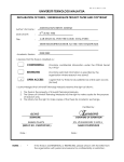
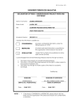
UNIVERSITI TEKNOLOGI MALAYSIA
DECLARATION OF THESIS / UNDERGRADUATE PROJECT PAPER AND COPYRIGHT
Author’s full name :
Date of birth
:
MOHAMAD KHUSAINI BIN ISA
10 JANUARY 1986
Title
LAB MANUAL FOR LOGIC ANALYZER
:
Academic Session:
2009/2010 2
I declare that this thesis is classified as:
CONFIDENTIAL
(Contains confidential information under the Official Secret
Act 1972)*
RESTRICTED
(Contains restricted information as specified by the
organisation where research was done)*
OPEN ACCESS
I agree that my thesis to be published as online open access
(full text)
I acknowledged that Universiti Teknologi Malaysia reserves the right as follows:
1. The thesis is the property of Universiti Teknologi Malaysia.
2. The Library of Universiti Teknologi Malaysia has the right to make copies for the purpose
of research only.
3. The Library has the right to make copies of the thesis for academic exchange.
Certified by:
SIGNATURE
SIGNATURE OF SUPERVISOR
860110 – 01 – 5327
NOTES :
(NEW IC NO. /PASSPORT NO.)
NAME OF SUPERVISOR
Date: April 21, 2010
Date :
*
If the thesis is CONFIDENTIAL or RESTRICTED, please attach with the letter from
the organisation with period and reasons for confidentiality or restriction.
ABSTRACT
Logic analyzer is a device used to analyze the working of any sort of digital
circuit. The aim of this project is to build a lab manual for the logic analyzer. Later, this
thesis will explain in detail every element used in this project including the modes and
functions that can be used in by logic analyzer. The most crucial part of this project is the
process on building the lab manual on how to use the logic analyzer. The manual will be
divided into two parts, the Timing Mode Analyzer and State Mode analyzer. A sequent
counter circuit will be used as the test subject for the timing analyzer part while the Flight
68k board will be used as the test subject for state analyzer part. Further, the result of this
project is proves by executing every part of the lab manual and the result gather from
executing the lab manual is discuss. In the end of this project, the usage of logic analyzer
is explored and a complete lab manual for the logic analyzer that will be able to help the
student to learn to use the logic analyzer is built. This lab manual will teach the student
on how to setup the manual analyzer for usage on various functions and modes. Also it
will help the student to learn on how to probe the circuit according to the type of circuit
to analyze. Furthermore the lab manual will also expose the student on writing and
assembling of a program.
ABSTRACT
Logic analyzer adalah alat yang digunakan untuk menganalisa sebarang jenis litar
digital. Tujuan projek adalah untuk menbina sebuah panduan untuk menggunakan ‘logic
analyzer’. Seterusnya, thesis ini akan menerangkan secara terperinci kesemua elemen
yang digunakan di dalam projek ini termsuklah kesemua mod dan fungsi yang boleh
digunakan dalam ‘logic analyzer’. Bahagian terpenting di dalam projek ini adalah proses
menghasilkan panduan untuk menggunakan ‘logic analyzer’. Panduan ini akan
dibahagikan kepada dua bahagian, ‘Timing Mode Analyzer’ dan ‘State Mode Analyzer’.
Sebuah litar pengira akan digunakan di dalam bahagian ‘Timing Mode Analyzer’
manakala papan Flight 68k akan digunakan dalam bahagian ‘State Mode Analyzer’.
Selanjutnya hasil projek ini akan dibuktikan dengan melaksanakan kesemua bahagian di
dalam panduan ini dan keputusannya dibincangkan. Pada penghujung projek ini nanti,
kesemua cara menggunakan ‘logic analyzer’ akan dibuat dan sebuah ‘Lab Manual’ untuk
‘logic analyzer’ yang mana ia akan membantu pelajar mempelajari cara menggunakan
‘logic analyzer’ akan dihasilkan. Panduan ini nanti akan mengajar pelajar tentang cara
menyediakan ‘logic analyzer’ untuk pelbagai fungsi dan mod analisis. Selain itu pelajar
juga akan mempelajari cara memprob litar dengan betul menikut jenis litar yang
dianalisis. Selanjutnya ‘Lab Manual’ ini juga akan mendedahkan pelajar kepada
penulisan dan penghimpunan sesebuah program.
TABLE OF COTETS
CHAPTER
1
2
TITLE
PAGE
DECLARATIO
I
DECLARATIO
II
ABSTRACT
III
ABSTRAK
IV
TABLE OF COTETS
V
LIST OF TABLES
VIII
LIST OF FIGURES
IX
LIST OF APPEDICES
X
ITRODUCTIO
1
1.1 Problems Statement
2
1.2 Objective
2
1.3 Project Scope
3
1.4 Project Planning
3
LITERATURE REVIEW
5
2.1 Logic Analyzer
6
2.1.1 Triggering
7
2.1.2 Timing Analyzer mode
7
2.1.3 State Analyzer mode
8
2.2 Probe
2.2.1 Combination POD
2.2.1 Disassembler POD
9
9
10
2.3 Test Hardware: Sequent Circuit
2.3.1 Circuit Schematic
11
2.3.2 4026 IC
12
2.4 Test Hardware: Flight 68k Board
14
2.5 68k Program Assembler
16
2.5.1 68k EASy68K
16
2.5.2 Command Prompt
19
2.6 Hyper Terminal
3
11
METHODOLOGY
20
22
3.1 Part 1: Timing Analyzer
23
3.1.1 Connecting the Logic Analyzer to the
Sequent Circuit.
23
3.1.2 Setup the Logic Analyzer to Analyze the
Sequent Circuit.
3.1.3 Analyzing the Sequent Circuit
3.2 Part 2: State Analyzer
3.2.1 Part 2.1: Setup
24
25
26
27
3.2.2 Part 2.2: Assembling Program and
preparing .BI file
28
3.2.3 Part 2.3: Download a Program into the
Microprocessor and Trigger the program
using Hyper Terminal on Window XP
28
4
RESULT
29
4.1 Part 1: Timing Analyzer
30
4.1.1 Instruction of Part 1 of the Lab Manual
30
4.1.2 Result of Part 1 of the Lab Manual
31
4.2 Part 2: State Analyzer
33
4.2.1.1 Instruction of Part 2.1 of the Lab Manual 33
4.2.1.2 Result of Part 2.1 of the Lab Manual
36
4.2.2.1 Instruction of Part 2.2 of the Lab Manual 37
4.2.2.2 Result of Part 2.1 of the Lab Manual
39
4.2.3.1 Instruction of Part 2.3 of the Lab Manual 41
4.2.3.2 Result of Part 2.1 of the Lab Manual
5
6
46
DISCUSSIO
48
5.1 Logic Analyzer Categories
49
5.2 Probing the Circuit
49
5.3 Analyzing a System
50
5.4 Trigger Function
50
COCLUSIO AD SUGGESTIOS
51
6.1 Conclusion
51
6.2 Suggestion
52
REFERECES
53
Appendix A
54
Appendix B
71
Appendix C
73
LIST OF TABLES
O.
TITLE
PAGE
1.1
Gantt chart for FYP 1
3
1.2
Gantt chart for FYP 2
4
2.1
4026 sequent table
12
LIST OF FIGURES
O.
TITLE
PAGE
2.1
Logic Analyzer
6
2.2
Timing analyzing
7
2.3
State analyzing
8
2.4
Combination POD
9
2.5
Disassembler POD for 68000
10
2.6
Sequent circuit schematic
11
2.7
4026 IC layout
13
2.8
Flight 68k Board
14
2.9
Connection between 68k microprocessor and 27C64 EPROM
on the Flight 68k board
15
2.10
Program Editor of EASy68K software window
16
2.11
Program writing using EASy68K software.
17
2.12
Program debugging using EASy68K software
17
2.13
Listing File obtain using EASy68K software.
18
2.14
Command Prompt
19
2.15
Assembling and produce .BI file using Command Prompt
19
2.16
HyperTerminal on Window XP
20
2.17
HyperTerminal Prompt windows
21
3.1
Connections between the logic analyzer and the
Combination POD
23
3.2
Probe label on the back of the Combination POD
24
3.3
Probe connected to the circuit
24
3.4
Sample result from the logic analyzer
25
3.5
Planning for part two of the lab manual
26
3.6
EPROM on Flight68k board
27
4.1
Instruction of Part 1 of the Lab Manual
30
4.2
Result of Part 1 of the Lab Manual
31
4.3
Instruction of Part 2.1 of the Lab Manual
33
4.4
Result of Part 2.1 of the Lab Manual
36
4.5
Instruction of Part 2.2 of the Lab Manual
37
4.6
Result of Part 2.2 of the Lab Manual
39
4.7
Instruction of Part 2.3 of the Lab Manual
41
4.8
Result of Part 2.3 of the Lab Manual
46
LIST OF APPEDICES
APPEDIX
TITLE
PAGE
A
Lab Manual for Logic Analyzer
54
B
Schematic for Part 1
71
C
The program used in Part 2
73
Chapter 1
Introduction
This chapter will explain the problems statement, objectives, scope of work and
the project planning for Final Year Project 1 (FYP 1) and Final Year Project 2 (FYP 2).
This project will be revolving around the usage of the logic analyzer. The vital part of
this project is to explore the important function and analysis that can be done using the
logic analyzer and produce the Lab Manual that can help the student to understand more
on how to use the logic analyzer.
1.1 Problems Statement
Went discussing on analyzing and debugging the digital system, logic analyzer is
something that should be consider. Logic analyzer can prove to be a very useful and
powerful tool to analyze and debug a circuit. But not all students can use the logic
analyzer.
There have been several projects that had been done by the student from Faculty
of Electrical Engineering related to this project. The earlier projects were able to produce
the prototype of the lab manual for the logic analyzer for certain type of circuit and
analyzer mode. By completing this project a fully commissioned lab manual on logic
analyzer will be able to be produced.
1.2 Objective
Two objectives are to be archive in this project:
1
To build a complete lab manual for a Logic Analyzer that covers most aspect and
function on logic analyzer.
2
To built a lab manual that can be use by the students to fully understand on how to
work a logic analyzer.
1.3 Project Scope
The scope of this project includes:
1
To explore any function on the logic analyzer that can be used for study purpose.
2
To build a correct connection between the test hardware (microprocessor board, and
sequential circuit) and the logic analyzer. After the connection are correctly
connecting the logic analyzer to will be used to observe the working of the test
hardware.
3
To built a lab manual on how to use the logic analyzer.
1.4 Project Planning
TASK
SCHEDULE
Meeting Coordinator
Meet Supervisor
Analyze and find
information on the
title
Get comfirmation
on the title
Check the manual
for the logic analyzer
Study the previous
thesis
Prepare for
presentation
Writing Report
3
4
5 6
7
Week
8 9 10 11 12 13 14 15 16
Table 1.1 Gantt chart for FYP 1
TASK
SCHEDULE
Reseaching counter
circuit
Design counter
circuit
Find the information
on the state and
timing analysis
study the Flight68k
Learn to use
Hyper Terminal
Design the full
Experiment
Built the counter
circuit
Complete first part
of the manual
Complete second part
of the manual
Complete Third part
of the manual
Ready for
Demonstration
Thesis writing
1
2
3
4
5
6
Week
7 8
9
Table 1.2 Gantt chart for FYP 2
10 11 10 13 14 15 16 17
Chapter 2
Literature Review
The main purpose of this project is to produce a lab manual on using the logic
analyzer. The manual are consist of several experiment that will be using the entire
instrument that will be explain in this chapter later. The purpose of this chapter is to
explain in detail every element used in this project. First of all this chapter will explain on
the logic analyzer which is the vital part of this project. The other vital part of this project
is probing the circuit. This chapter will also explain the two kind of probe that will be use
in the experiment. The rest of this chapter will explain any other element that will be used
for this project.
2.1 Logic Analyzer
Figure 2.1 Logic Analyzer
A logic analyzer is an electronic instrument that displays signals in a digital
circuit that are too fast to be observed and presents it to a user so that the user can more
easily check the operation of the digital system with precision. It is commonly used to
debug and analyze a circuit that makes it similar to the oscilloscope. The main
advantages over an oscilloscope are that more than 4 channels can be watched at the
same time. The other advantage is, other than just a timing diagram, the logic analyzer
can also analyze in state analyzer mode. Furthermore the logic analyzer the logic analyzer
can trigger or record right where it’s needed. This function will be explained later on in
this chapter. In this project the LA4800 logic analyzer from Thurlby Thandar will be used
in the experiment.
2.1.1 Triggering
Besides having many more channels available than an oscilloscope, the other
main advantage of a logic analyzer is its ability to record only the data of interest, even if
it’s s buried in the middle of a complex and long programming. A logic analyzer can
trigger on a complicated sequence of digital events, and then capture a large amount of
digital data from the test subject. For example, a trigger could be designed to start
recording only after seeing a particular bit pattern 4 times, followed by a delay, followed
by another particular pattern. The usage of this function will be showed later on in the
experiment.
2.1.2 Timing Analyzer mode
There are two modes that can be used in analyzing using the logic analyzer. One
of it is the timing mode, and the other is the state analyzer mode. The state analyzer mode
will be explained later on in this chapter.
In Timing Analyzer mode, the logic analyzer uses its own internal clock to decide
when to sample. This mode provides more resolution, and is useful for making sure all
the signals in the test circuit (the sequent circuit) are transitioning correctly, in other
word, data will be stable in sufficient amount of time before and after the clock signal.
This mode will be showed in the experiment (see Appendix A).
Figure 2.2 Timing analyzing
2.1.3 State Analyzer mode
In State Analyzer mode, the logic analyzer samples the entire test signals on the
test subject (in this case the microprocessor) on its own clock signal, so the analyzer sees
the data exactly the same as the test circuit. The part two of the experiment (see
Appendix A) will instruct the student on how to use the State Analyzer mode in the logic
analyzer.
Figure 2.3 State analyzing
2.2 Probe
The most common method of data capture for logic analyzers is through a probe.
A logic analyzer can measure anything electronic if it has the proper probe connected.
Typically, logic analyzer will analyze the data buses. The probes will try to tap into the
signals that being passed through a data bus or wire of the circuit. In this project, there
will be two kind of probe that will be used in the experiments, the Combination POD for
the sequent circuit and the Disassembler POD for the microprocessor circuit.
2.2.1 Combination POD
To be able to capture the data on the circuit, the probing of the circuit need to be
done correctly. Thus the combination POD will be use to probe the sequent circuit. The
probing will be showed in the first part of the experiment (see Appendix A).
Figure 2.4: Combination POD
2.2.1 Disassembler POD
As explain, the probing is vital in order for the logic analyzer to be able to analyze
the data from the circuit. In the second part of the experiment (see Appendix A), the
microprocessor will be used, thus the Disassembler POD will be used to probe the
microprocessor.
Figure 2.5: Disassembler POD for 68000
2.3 Test Hardware: Sequent Circuit
Two kind of circuit will be used as the test subjects for this project the sequent
circuit and the microprocessor circuit. A counter circuit is selected to be used as the test
subject. The circuit contains the 4026 IC which has a decade counter and a decoder for
the 7 segment display. Since the project is to use the logic analyzer to analyze the circuit,
hence this experiment is design to analyze the working of 4026 IC.
2.3.1 Circuit Schematic
As explained, the analysis is on the 4026 IC. However a proper connection needs
to be done for the circuit to function. Below is the schematic use to connect the 4026 IC.
Figure 2.6 Sequent circuit schematic
This is the parts require for the circuit:
•
•
•
•
•
•
Resistors: 10k, 47k
555 timer IC
Capacitor: 1µF 16V radial
4026 counter and display driver IC
LEDs ×8 or common-cathode 7-Segment Display.
9V battery
2.3.2 4026 IC
The 4026 IC is the ideal choice for the experiment since it simple enough to built
but still have many signal that can be analyze using the logic analyzer. Simply put to
words, 4026 IC have a counter and the 7-segment display in one integrated circuit. The
count advances as the clock input becomes high. The outputs a-g go high (1) to light the
appropriate segments of a 7-segment display (this case the circuit are using the LED to
put a test to the student) as the count advances. The maximum output current is about
1mA with a 4.5V supply and 4mA with a 9V supply. This is sufficient to directly drive
many 7-segment LED displays. The table below shows the segment sequence in detail.
Count
0
1
2
3
4
5
6
7
8
9
a
1
0
1
1
0
1
1
1
1
1
b
1
1
1
1
1
0
0
1
1
1
c
1
1
0
1
1
1
1
1
1
1
d
1
0
1
1
0
1
1
0
1
1
e
1
0
1
0
0
0
1
0
1
0
Table 2.1 4026 sequent table
f
1
0
0
0
1
1
1
0
1
1
g
0
0
1
1
1
1
1
0
1
1
h
1
1
1
1
1
0
0
0
0
0
Below is the layout of the 4026 IC and the instruction on how to connect the IC:
Figure 2.7 4026 IC layout
The reset input should be low (0V) for normal operation (counting 00-9). When
high it resets the count to zero.
The disable clock input should be low (0V) for normal operation. When high it
disables counting so that clock pulses ar
aree ignored and the count is kept constant.
The enable display input should be high (+Vs) for normal operation. When low it
makes outputs a-gg low, giving a blank display. The enable out follows this input
but with a brief delay.
The ÷10 output (h in table) iis high for counts 0-4
4 and low for 5-9,
5 so it provides
an output at 1/10 of the clock frequency. It can be used to drive the clock input of
another 4026 to provide multi
multi-digit counting.
The not 2 output is high unless the count is 2 when it goes low.
2.4 Test Hardware: Flight 68k Board
In this project, the Flight 68k board will be use as the test hardware. The 27C256
EPROM and the 68k microprocessor on the Flight 68k board will be used as the test
subject on the experiment (see Appendix A). Below is the figure of the Flight 68k Board:
Figure 2.8 Flight 68k Board (square mark is the 68k microprocessor and 27C256
EPROM)
27C256 EPROM is a non-volatile device that the data retained without power.
The Figure 2.8 shows that the two EPROM was use on the 68000 microprocessor board
because it has two parts of memory which is even and odd. Later on, the experiment will
show the student on how to analyze the program that already install in the 27C256
EPROM. Figure below show the connection between the 68k microprocessor and the
EPROM:
Figure 2.9 Connection between 68k microprocessor and 27C64 EPROM on the Flight
68k board.
2.5 68k Program Assembler
Parts of the experiment were to built and assemble the program before it is
downloaded into the Flight 68k board. So the 68k program assembler software is needed
to do the assembling. To there is many choice of program assembler software can be use
for example the EASy68K and 68k Assembler software or we can also use the Command
Prompt. For this project the EASy68K software and the Command Prompt in the
Window XP will be used to write and assemble the program.
2.5.1 68k EASy68K
The use of the EASy68K in this project is to write and make the debugging of the
program. The EASy68K software is choose for this project because it will make the
program writing process easier and faster. Later on, the programs that have been written
can be debugging to make sure the program doesn’t have any error. After the simulation
is done, the software can produce the full listing file for the program. The full program
and the listing file is show in the Appendix C. Figure below will show the writing process
and the listing file obtain using EASy68K software.
Figure 2.10 Program Editor of EASy68K software window
Figure 2.11 Program writing using EASy68K software.
Figure 2.12 Program debugging using EASy68K software.
Figure 2.13 Listing File obtain using EASy68K software.
2.5.2 Command Prompt
Command Prompt can be use as the editor and assembler to the make a program.
However in this project the usage of Command Prompt is only to assemble the program.
It is necessary since the experiment will be using the Flight 68k board as the test subject,
the assemble program will need be in the .BIN file. Later on, the experiment will show
the student on how to assemble the program using the Command Prompt and how to
produce the .BIN file.
Figure 2.14 Command Prompt
Figure 2.15 Assembling and produce .BIN file using Command Prompt
2.6 Hyper Terminal
HyperTerminal, which comes with Window XP, can be used to obtain diagnostic
information from your modem after an ISP session, or to make test calls to BBS or ISP
numbers; it can also be used to get information from your modem about the
firmware/driver version installed. In the experiment, student will need to use the Hyper
Terminal in order to download the assemble program into the 68k microprocessor on the
Flight 68k Board. Refer to the lab manual in Appendix A for the full instruction to
operate the HyperTerminal.
Figure 2.16 HyperTerminal on Window XP
Figure 2.17 HyperTerminal Prompt windows
Chapter 3
Methodology
The purpose of this chapter is to explain the method done in order to archive the
objective for this project. The project is to build a lab manual that can help the student to
understand on how to use the logic analyzer. The Lab Manual is consisting of an
experiment on operating the logic analyzer. This Lab Manual will be divided into two
parts of experiment, the timing analyzer, and the state analyzer. In timing analyzer part,
the experiment will use a simple sequent counter circuit. In this part of the Lab Manual, it
will guide the student the setups needed to analyze a sequent circuit using logic analyzer
and how to analyze the data generate by it. In state analyzer part, the experiment will be
using the Flight 68k microprocessor board as the test subject. This part will explain to the
student the setups need to analyze a microprocessor circuit using logic analyzer and how
to analyze the data generate by it. In addition this part will also explain to the student on
how to prepare a file to download into the microprocessor.
3.1 Part 1: Timing Analyzer
As explain before this part will guide the student to use the Timing Analyzer
Mode function on the logic analyzer. Simply put in word, this part of the Lab Manual
contain three steps, connecting, setup, and analyze. Later on this step will be explained in
detail.
3.1.1 Connecting the Logic Analyzer to the Sequent Circuit.
In order to have an accurate analysis, the connection between the circuit and the
logic analyzer need to be accurate. Also the choosing of the probe use should be
appropriate. At first, the student will be introducing to the Combination POD and how to
connect it into the logic analyzer. Then student will be instruct on how to connect the
Combination POD probe correctly to the circuit (refer to the Lab Manual in Appendix A).
Figure below showed the connection made between the logic analyzer and the
Combination POD also the probe label on the back of the Combination POD:
Figure 3.1 Connections between the logic analyzer and the Combination POD
Figure 3.2 Probe label on the back of the Combination POD
Figure 3.3 Probe connected to the circuit
3.1.2 Setup the Logic Analyzer to Analyze the Sequent Circuit.
After connecting the circuit the Lab Manual will explain on how to setup the logic
analyzer. Some logic analyzer can automatically detect the setup need for the circuit. But
in this case most of the setup will need to be made manually. The full instruction on
making the setup is explain in the Lab Manual (refer Appendix A)
3.1.3 Analyzing the Sequent Circuit
Finally the Lab Manual will guide the student on how to read and analyze the data
from the logic analyzer. Later the student will also be tested on their comprehension on
analyzing the data from the logic analyzer to make sure student will really understand to
work with logic analyzer. Figure below showed the sample result from the logic analyzer:
Figure 3.4 Sample result from the logic analyzer
3.2 Part 2: State Analyzer
In this part, the experiment is to analyze the working of 68k microprocessor on
the Flight 68k Board using the logic analyzer in State Analyzer Mode. This part of
experiment will be divided
ivided 3 part
partss that will be explained later on this chapter.
chapter The flow
chart bellow will show the plan of this part of the Lab Manual:
Figure 3.5 Planning for part two of the lab manual
3.2.1 Part 2.1: Setup
The first part of the second part of the Lab Manual is to guide the student on how
to setup the logic analyzer to analyze in state mode analyzer. Also, this part of Lab
Manual will guide the student on how to connect the microprocessor to the logic analyze
analyzer
using the Disassembler POD.
POD. After the connection is made, the lab Manual will guide the
student to trigger the program that already programmed into the EPROM on the Flight
68k board. Finally the lab Manual will guide the student on how to analyze the data
trigger on the logic analyzer. Refer to the Part 2.1 of the Lab Manual (Appendix A) for
the full instruction.
Figure 3.6 EPROM on Flight68k board
3.2.2 Part 2.2: Assembling Program and preparing .BI file
In this part of the Lab Manual, student will be guide on how to assemble the
program that already been write earlier using the EASy68k software. The assembling of
the program will be done using Command Prompt application on the Window XP. This
part is necessary in order to get the .BIN file need to be downloaded into the Flight 68k
board. Refer to the Part 2.2 of the Lab Manual (Appendix A) for the full instruction.
3.2.3 Part 2.3: Download a Program into the Microprocessor and Trigger the
program using Hyper Terminal on Window XP.
In this part of the Lab Manual, it will guide the student on how to download a
program into the microprocessor and instruct the logic analyzer to trigger the data on the
address wanted by the user.
First step of this of the experiment is to set the trigger address the user wants to
trigger. In this experiment the student will be triggering from the origin address of the
program that has been written earlier.
After the triggering address is set, student will be instructed to make the
connection between the Flight 68k and the PC. This connection is established using the
Hyper Terminal. After the connection is properly establish, the .BIN file that already
been create in part 2.3 is download into the 68k microprocessor on the Flight 68k Board.
After downloading is complete, the analysis of the 68k microprocessor student
will be instructed to start the analysis. The triggering of the data that need to be analyzed
will be start after the student gives the instruction to the 68k microprocessor to go to the
address that has been set earlier in the experiment. Refer to the Part 2.3 of the Lab
Manual (Appendix A) for the full instruction.
Chapter 4
Result
This chapter will be discussing the output of the project. As we know from the
beginning of the project, the main objective of this project is to build the Lab Manual for
the logic analyzer. Hence later on, this chapter will be discussing the complete Lab
Manual part by part and explaining how it can help student on understanding the working
of the logic analyzer and further helping the student to learn on how to use the logic
analyzer.
4.1 Part 1: Timing Analyzer
4.1.1 Instruction of Part 1 of the Lab Manual.
In this part of Lab manual student should be able to learn on how to use timing
mode analyzer on the logic analyzer. Figure below showed the instruction on the Part 1 of
the Lab Manual
Figure 4.1 Instruction of Part 1 of the Lab Manual
4.1.2 Result of Part 1 of the Lab Manual.
Below is the result gather from the Part 1 of the Lab Manual after executing the
experiment.
Figure 4.2(a) Result of Part 1 of the Lab Manual
Figure 4.2(b) Result of Part 1 of the Lab Manual
4.2 Part 2: State Analyzer
4.2.1.1 Instruction of Part 2.1 of the Lab Manual
In this part, student should be able to learn to make the state analyzer mode setup
and on how to trigger the program that already programmed into the EPROM on the
Flight 68k Microprocessor board. Figure below showed the instruction on the Part 2.1 of
the Lab Manual.
Figure 4.3(a) Instruction of Part 2.1 of the Lab Manual
Figure 4.3(b) Instruction of Part 2.1 of the Lab Manual
Figure 4.3(c) Instruction of Part 2.1 of the Lab Manual
4.2.1.2 Result of Part 2.1 of the Lab Manual.
Below is the result gather from the Part 2.1 of the Lab Manual after executing the
experiment.
Figure 4.4 Result of Part 2.1 of the Lab Manual
4.2.2.1 Instruction of Part 2.2 of the Lab Manual.
In this part, student should be able to learn how to prepare the .bin file to be
downloaded into the Flight 68k Microprocessor board. Figure below showed the
instruction on the Part 2.2 of the Lab Manual.
Figure 4.5(a) Instruction of Part 2.2 of the Lab Manual
Figure 4.5(b) Instruction of Part 2.2 of the Lab Manual
4.2.2.2 Result of Part 2.1 of the Lab Manual.
Below is the result gather from the Part 2.2 of the Lab Manual after executing the
experiment.
Figure 4.6(a) Result of Part 2.2 of the Lab Manual
Figure 4.6(b) Result of Part 2.2 of the Lab Manual
4.2.3.1 Instruction of Part 2.3 of the Lab Manual.
In this part, student should be able to learn how to make the connection on the
Flight 68k Microprocessor board using the Hyper Terminal. Also student should be able
learn how to download the program into the Flight 68k Microprocessor board and how to
trigger the logic analyzer to analyze the program that have been download into the
microprocessor. Figure below showed the instruction on the Part 2.3 of the Lab Manual.
Figure 4.7(a) Instruction of Part 2.3 of the Lab Manual
Figure 4.7(b) Instruction of Part 2.3 of the Lab Manual
Figure 4.7(c) Instruction of Part 2.3 of the Lab Manual
Figure 4.7(d) Instruction of Part 2.3 of the Lab Manual
Figure 4.7(e) Instruction of Part 2.3 of the Lab Manual
4.2.3.2 Result of Part 2.1 of the Lab Manual.
Below is the result gather from the Part 2.3 of the Lab Manual after executing the
experiment.
Figure 4.8(a) Result of Part 2.3 of the Lab Manual
Figure 4.8(b) Result of Part 2.3 of the Lab Manual
Chapter 5
Discussion
From the very beginning of this project, a lot of research has been done
concerning the usage of the logic analyzer. The information gather from the research then
used to build the Lab Manual which is the main objective of the project. However there is
still some of the aspect concerning the logic analyzer is not include in this project. One of
the main reasons is because it is not helping on archiving the objective of the project.
Thus this chapter is dedicated on discussing all elements concerning the logic analyzer.
5.1 Logic Analyzer Categories
In this project the logic analyzer used was the LA4800 logic analyzer from
Thurlby Thandar. This logic analyzer can be categories in the ‘mainframes’ category. It is
consist of a chassis containing the display, controls, control computer, and multiple slots
into which the actual data capturing hardware is installed.
There is also two other category of logic analyzer, the ‘standalone units’ and ‘PCbased’. The ‘standalone units’ are the kind of logic analyzer that integrates everything
including the oscilloscope into a single package, which usually installed at the factory.
The “PC-based” logic analyzers is the kind of logic analyzer that have its
hardware connects to a computer through a USB or LPT connection and then relays the
captured signals to the software on the computer. These instruments are less expensive
than either mainframes or standalone units although they lack the sophisticated
functionality. These devices are typically much smaller, because they do not need
displays or hardware input such as dials.
5.2 Probing the Circuit
The logic analyzer can be used to analyze any digital circuit as long as it is probe
properly. However there is a several issue concerning the probing of the circuit. Even
thought the logic analyzer specialty is to read many channel in the circuit, too many
probe may cause the capacitance in the circuit to increase hence causing the reading on
the logic analyzer become inaccurate. Other than too many probing on the circuit, the
cable use to connect the probe to the logic analyzer can also cause the increase of
capacitance in the circuit.
Thus in order to reduce this effect, some of the logic analyzer uses a low
capacitance material for the probe. Also reducing the length of the connecter cable can
also reduce this effect.
5.3 Analyzing a System.
Most of the program will go through the debugging process after the designing
process. This process can be done using debugging software like EASy68k.This software
will provide the analysis of the program. So on most digital design can be analyze during
the design stage of the system.
However once the program is install into the hardware, we cannot what really
happen inside the system. Thus the logic analyzer can be very useful in this case
especially if there is no information on the programming of the system. This has been
showed in the part 2.1 of the Lab Manual where the logic analyzer is used to trigger the
data from the EPROM on the Flight 68k board.
5.4 Trigger Function
In part 2.3 of the Lab Manual, the student is showed on how to trigger the data
from the system. With this function, a logic analyzer user will be able to observe the
specific data that need to be observed. This function is also proving to be very useful
especially if the logic analyzer have a limited amount of memory.
Chapter 6
Conclusion and Suggestion
6.1 Conclusion
Since the very beginning the objective of this project has been state clearly is to
build a logic analyzer. Later, a counter circuit is build and successfully analyzes using the
logic analyzer in the Timing Analyzer Mode. Also by using the State Analyzer Mode, the
working of the microprocessor on the Flight68k board has been successfully analyzes.
Further, a lab manual for the logic analyzer is build and all the experiments in the manual
were execute and proves.
In conclusion, this project is successfully archived its objective which is to build a
Lab Manual for the logic analyzer. By practicing using this lab manual, student should be
able to use both timing and state analyzing mode in the logic analyzer.
Other than already state as above, in this project student will be learning on how
to choose an appropriate probe according to the circuit that will be analyze. Further more
in this project will be expose on writing and assembling program and usage of Hyper
Terminal.
6.2 Suggestion
There are still a few improvements that can be done if this project is to be
continued in the future. These are some suggestion for improvement:
1. The use of more advance logic analyzer can be considered. This is due to the
accuracy of the analysis, number of function available, and the deeper memory to
analyze more data.
2. The analysis process can be done more with efficient if there is a print function
available.
3. In the ‘State Analyzer Mode’ part in this project, Flight 68k board is used as the
test subject, in the future, it is suggested to use variable test subject so a variable
kind of probe can be used.
REFERECES
1. William D. Cramer, Gerry Kane. 68000 microprocessor handbook. McGraw-Hill.
2nd edition. 2006
2. Joseph J. Carr. 68000 User's Manual. 1987
3. Walter A. Triebel, Avtar Singh. The 68000 and 68020 microprocessors: hardware,
software, and interfacing techniques. Prentice Hall, University of Michigan. 1991
4. Walter A. Triebel, Avtar Singh. The 68000 microprocessor: architecture,
software, and interfacing techniques. Prentice Hall, University of Michigan. 1986
5. THURLBY LA3200/4800 Microprocessor disassembler POD Operating Manual
6.
Ahmad. Aimi Ruzaimi. Lab Manual for Logic Analyzer: 68000 Microprocessor
as the Test Hardware.
7. Abdullah Suhaimi. Nor Aminah. Lab Manual for Logic Analyzer: 68HC11
Microcontroller as the Test Hardware.
Appendix A
Lab Manual for Logic Analyzer.
OBJECTIVE:
1. To learn how to use the Logic Analyzer.
2. To study the working of the 4026 IC
3. To study the programming inside the Flight 68k Microprocessor board.
EQUIPMET:
1. Logic Analyzer.
2. Combination POD
3. Counter circuit with 4026 IC
4. Disassembler POD for 68000.
5. Flight 68k Microprocessor and application board.
THEORY:
A Logic Analyzer is an electronic instrument that could display multiple digital
signals on a single screen. They are usually used for capturing data in digital systems that
have too many channels to be examined with an oscilloscope. Software running on the
Logic Analyzer can convert the captured data into timing diagrams, protocol decodes,
state machine traces, assembly language, or correlate assembly with source-level
software. A logic analyzer can be used to analyze any kind of digital circuit as long as it
is probe correctly.
Part1: Timing Mode Analyzer
Instruction
1. This experiment is to use a logic analyzer to analyze the working of counter
IC 4026.
2. Connect the Combination POD to the logic analyzer. See figure below:
3. Connect the circuit with the probe on the Combination POD. Use appendix B
as a referent. Make sure you connect the ground as well. The label for the
probe is written on the back of the Combination POD.
4. Switch the logic analyzer and wait till the option screen showed. Select
1(CONFIGURATION).
5. Put the clock as internal and press menu.
6. Select 2(Timing Diagram) and select (Format).
7. Rename:
ADDR00 ADDR01 ADDR02 ADDR03 A
B
C
D
.
.
ADDR07 H
8. Select (Exit) after renaming.
9. Press “run” and than select “fast roll”
10. Switch on the circuit, the output should be showed in the logic analyzer
screen.
11. Fill the result form.
Part1: Timing Mode Analyzer
Result
1. Draw the output show in the logic analyzer at least for 17 clock cycle.
Answer:
2. Decode the signal from the output (refer to Appendix B) and fill the table below.
Answer:
3. From the output table above, discuss the pattern create by the output on the logic
analyzer.
Answer: The result on the logic analyzer shows that the output sequent is
counting increasingly from 0 to 9 but in a random sequent
sequent.
4. The circuit is design to count increasing from 0 to 9 and keep looping. From the
output show in the logic analyzer, dose the result showed that the circuit is design
correctly.
Answer: Yes
Part2: State Mode Analyzer
Part 2.1: Setup
Instruction
1. Connect the Disassembler POD 68000 to the logic analyzer. Make sure that the
Disassembler POD 68000 is connecting correctly on MC68000 chip.
Figure: connection to the logic analyzer
2. Switch on the Logic Analyzer then check the 68000 Disassembler POD was
Assemble or not.
3. Clip the 68000 Disassembler POD to the chip MC68000 on 68000Microprocessor
Board. Make sure the connection is correct (Pin 1 on DP 68000 to Pin 1 on chip).
Figure: 68000 Disassembler POD
figure: Connection
between 68000
Disassembler POD to
68000 microprocessor
4. Select Confirm
Figure: The disassembler has been loaded
5. 5.Wait until the option menu appear and select 1(CONFIGURATION)
I.
Set clock selected as EXTERNAL
Press MENU.
II.
6. Select3(STATE LISTING)
I.
Confirm that, no data on the Logic Analyzer
Select GOTO TRG until it shows the ‘0000’ POS on the upper left of
II.
Logic Analyzer display (Starting point it will be triggering).
Press MENU.
III.
7. Select 4(TRIGGER SETUP)
On Address HEHEX, Trig Wrd, set as 000000.
I.
II.
Press MENU.
8. Select 7 (68000 DISASSEMBLER VER (1.01))
Press RUN button on right side of Logic Analyzer.
I.
II.
Select SINGLE on the list menu on the bottom.
9. Switch on the Flight 68k Microprocessor Board and press the reset button. The
logic analyzer will trigger the data from the EPROM on the Flight 68k
Microprocessor Board.
Figure: Logic analyzer Trigger Function
10. Fill the Result Form.
Result
1. Write the first 3 instruction from the logic analyzer.
Answer:
MOVE
MOVEA.L
CLR.L
#2700,SR
#004003F0,A7
004000CE
2. Referring to the cursor 0027 until 0029 from the logic analyzer, fill in the table
below.
Answer:
3. On cursor 0028 and 0029, what dose the system do?
Answer:
On cursor 0028 a data is being written and on cursor 0029, a data is being
read.
Part 2.2: Assembling Program and preparing .BI file
Instruction
1. Type or copy the pseudo code given into the EASy68K Assembler. Refer to
Appendix C
2. Save the file in .asm, and print it.
3. Run the program to make sure there is no error. Print the listing file.
4. Run the command prom
5. Type “cd\flt68k” change the directories into the flt68k.
6. Type “xasm <dir>:\<file name> <dir>:\<file name> <dir>:\<file name>”
for example If you save the file in E:\prog0900\zyus2 you should type:
“xasm E:\prog0900\zyus2 E:\prog0900\zyus2 E:\prog0900\zyus2”
7. Press enter and the it will show as below :
8. The .bin file should be in the same directories as the .asm file.
Result
1. The written program
2. Listing file from EASy68K
Part 2.3: Download a Program into the Microprocessor and Trigger the
program using Hyper Terminal on Window XP.
Instruction
1. Redo instruction 1 to 6 from part 2.1 if necessary .
2. Select 4(TRIGGER SETUP)
I.
II.
On Address HEHEX, Trig Wrd, set as 400400.
Press MENU.
3. Connect the serial cable into LK2 socket and
switch on the Flight 68k
Microprocessor Board.
4. Open the Hyper Terminal :
start|All Program|Accessories|Communication|Hyperterminal
5. Put the name and click ok.
6. Follow the procedure in the figures below
7. After getting the hyper terminal prom window push the reset button on the Flight
68k Microprocessor Board and press enter three times. The window should show
as below:
8. Type “lt” and press enter.
9. Click TRANSFER on the MENU, and then SEND TEXT FILE.
10. Search .bin file that you create before.
11. Select 7 (68000 DISASSEMBLER VER (1.01))
I.
Press RUN button on right side of Logic Analyzer.
Select SINGLE on the list menu on the bottom
II.
12. Back at the Hyper Terminal, type “go” and enter address “400400” after the
LOAD COMPLETED and press enter.
13. The logic analyzer should trigger and showed the listing of program that has been
downloaded into the microprocessor.
14. Fill the result form.
Result
1. Write the first 9 operation showed in the logic analyzer.
Answer:
MOVEA.L #$4003F0,A7
MOVE.B
#$80,0080000D.L
MOVE.B
#$00,00800005.L
MOVE.B
#$80,0080000F.L
MOVE.B
#$FF,00800007
MOVE.B
#00FF,D0
EOR
#%11111111,D0
MOVE.B
D0,PBDR
JMP
READAGA
2. Discuss the different output showed from the address 400406, 40040E,400416
and 40041E.
Answer:
If we take for example operation “MOVE.B
#$80,0080000D.L” on
address 400406 from the logic analyzer and compare it with the original
program that we download into the logic analyzer, we can actually see that it
the same as operation
“MOVE.B #$80,PACR” because, PACR is equal to 80000D. This is also
implies to the other address in question.
3. From the result showed above, is it true that the output on the logic analyzer is the
same as the output generate on the EASy68k.
Answer:
Yes
4. Redo step 2 but set the trigger address to 400406, press menu and redo step 7 till
12. Write the first 3 instruction show from the logic analyzer and discuss why the
result is the way it is.
Answer:
MOVE.B
#$80,0080000D.L
MOVE.B
#$00,00800005.L
MOVE.B
#$80,0080000F.L
The logic analyzer is showing this result because it is instructed to only
capture the data starting from the address 400406 which contain the
instruction
“MOVE.B #$80,0080000D.L”. Hence producing the result as showed
above.
Appendix B
Schematic for Part 1
4026 Counter IC Layout
The count advances as the clock input becomes high (on the rising
rising-edge). The
outputs a-gg go high to light the appropriate segments of a common
common-cathode
cathode 77-segment
display as the count advances. The maximum output current is about 1mA with a 4.5V
supply and 4mA
mA with a 9V supply. This is sufficient to directly drive many 77-segment
LED displays. The table below shows the segment sequence in detail.
The reset input should be low (0V) for normal operation (counting 00-9). When
high it resets the count to zero. Th
Thee disable clock input should be low (0V) for normal
operation. When high it disables counting so that clock pulses are ignored and the count
is kept constant. The enable display input should be high (+Vs) for normal operation.
When low it makes outputs aa-g low, giving a blank display. The enable out follows this
input but with a brief delay. The ÷10 output (h in table) is high for counts 00-4 and low for
5-9,
9, so it provides an output at 1/10 of the clock frequency. It can be used to drive the
clock input of another 4026 to provide multi
multi-digit
digit counting. The not 2 output is high
unless the count is 2 when it goes low.
LED Output Sequent
Appendix C
The program used in Part 2: