1
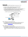
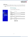
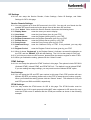
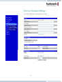
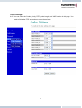
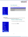
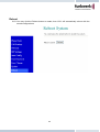
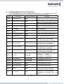
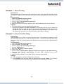
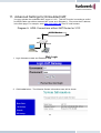
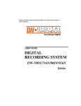
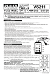
V101
SIP VoIP Telephone Adaptor
User Manual
V1.1m
Quick Guide
Step 1: Broadband (ADSL/Cable Modem) Connections for V101
A.
B.
C.
D.
Connect V101 LAN port to ADSL NAT Router as the following connection.
Connect V101 PC port to PC LAN port using a Category 5 LAN cable.
Connect V101 RJ11 PHONE port to a Telephone Set.
Connect the power adaptor to power on V101, and the POWER LED will be lit. In 5
seconds, the PHONE LED will start flashing 5 times and be ready for configurations.
E. Pick up the phone, the PHONE LED will be lit, and you should hear a dial tone.
F. Press #121# and #120# from the phone to check the DHCP status and the IP address (e.g.
192.168.1.100) for V101. After the IP announcement, please hang up.
a. ADSL Connections with external NAT Router for V101
ADSL Modem
NAT Router
Router IP: 192.168.1.1
LAN
V101 IP: 192.168.1.100
PC IP: 192.168.1.101
PC
Phone
Step 2: Settings for V101 with NAT Router
A. V101 is equipped with DHCP agent to automatically get an IP Address from NAT router
B. Press #120# from the phone to listen and check IP address (e.g. 192.168.1.100) for V101.
C. Enter the IP address from PC Web browser for V101 configuration settings.
Example: Enter http://192.168.1.100, if V101 IP address is 192.168.1.100
Step 3: Making Point-To-Point SIP Calls
A. While the PHONE LED is flashing continuously showing a successful registration in the SIP server.
B. Pick up the phone, and you should hear a dial tone.
C. Press 123456# to call the party with the number 123456 registered in the SIP server. Note
# is used to send out the call immediately. In a moment, you should hear the ring back tone,
and wait for the called party to answer. For more information, please refer to V101 user
manual.
TABLE OF CONTENTS
1. Introductions………………………………………………………………
1
2. Features ………………………………………………………………………
1
3. Standard Compliances……………………………………………
2
4. Packing Contents ……………………………………………………
2
5. LED Indicators……………………………………………………………
2
6. Installations & SIP Configurations ……………………
3
7. Default Reset from Telephone ……………………………
3
8. Configurations from Web browser……………………
4
9. Configurations from Telephone …………………………
26
10. Applications Examples…………………………………………
27
34
11. Advanced Settings for Embedded NAT …………
12. Trouble Shooting for Web Configurations ……
37
1. Introduction
The V101 is a single port Telephone Adaptor (TA) with SIP Protocols for Voice over IP (VoIP)
applications. Connecting to the Internet, the V101 can make a voice phone call over the
Internet from one IP to another. V101 provides two Ethernet LAN ports for connections to
Internet and Notebook PC, plus one phone port for telephone set. With an embedded
NAT/DHCP server, the V101 can be easily configured through the Web browser, and is very
suitable for ITSP (Internet Telephony Service Providers) customers and SOHO users to make
VoIP calls.
Each V101 requires an IP address, a subnet mask, and its gateway Router IP address for its
own use to connect to Internet. These three are available from your Internet service provider.
If the ITSP provides dynamic IP to customers, V101 user may enable PPPoE or DHCP
features to automatically get an assigned dynamic IP. Sometimes, the V101 Media Access
Control (MAC) hardware address may be required, and it is indicated at the bottom of V101.
Please refer to Section 8 Configuration from Web browser for detailed information.
2. Features
The V101 VoIP TA is equipped with one RJ11 connector for POTS, and two RJ45 connectors
for Router and PC connections. The V101 is featuring as the following
¾ Three LED Indicators for V101: POWER, PHONE, LAN
¾ RJ45 x 2 for Ethernet + RJ11 x 1 for FXS
¾ Web Browser and Telephone Configurations
¾ Embedded NAT/DHCP Server
¾ TCP/IP, UDP, RTP/RTCP, ICMP, ARP/RARP
¾ PPPoE/DHCP Client for Dynamic IP plus NAT, DNS, and DDNS Clients
¾ Support STUN server for NAT Traversal
¾ Interactive Voice Recording (IVR) for telephone IP status
¾ Speed Dial, Call Forward/Waiting, Call Transfer/Hold and 3-Way Conference
¾ Remote Firmware Upgraded with HTTP or TFTP server by Web PC
¾ Direct IP/URL Dial without SIP Proxy or Dial number via SIP server
¾ Telephone features: Volume Adjustment, Phone book, Speed Dial, Redial, and Flash
¾ Out-Band DTMF (RFC 2833) / In-Band DTMF / Send DTMF SIP Info
1
3. Standard Compliances
The V101 VoIP TA supports for the following standards
VoIP Protocol:
IETF RFC3261 and RFC 2543 for SIP
SIP Authentication: IETF RFC2069 and RFC 2617 for MD5
Speech Codec:
ITU-T G.711, G.723, G.729A/B, VAD and CNG
Echo Cancellation: ITU-T G.165/168
4. Packing Contents
Inside the package you should find:
(1) One V101 SIP TA
(2) One AC to 12VDC 1A Power Adaptor
(3) One User Manual CD
Please check if the packing is damaged or any component is missing. If so, please
contact your distributor.
5. LED Indicators and Connectors
On the front panel of V101, there are three LED indicators as the following
POWER: “On” indicates the power is normal
PHONE:
“On” indicates the telephone is Off-hook
“Flashing,” indicates successful registration at SIP server for V101
LAN:
“On” indicates the Ethernet LAN port is in Connection
Reset
Power
Phone
PC
2
LAN
6. Installations & SIP Configurations
1.
2.
3.
4.
5.
Connect V101 RJ45 LAN port to NAT Router using a Category 5 LAN cable.
Connect V101 RJ45 PC port to Notebook PC using a Category 5 LAN cable.
Connect V101 RJ11 PHONE port to a Plain Old Telephone Set (POTS).
Connect the power adaptor to power on V101, and the POWER LED will be lit constantly.
The PHONE LED indicators will be OFF for about 5 seconds and start flashing for 5
times, and remain OFF for VoIP configurations. The LAN LED will be constantly ON
when any one of RJ45 ports is connected. If the PHONE LED keeps flashing, it indicates
that V101 has successfully registered in the SIP server.
6. Pick up the phone, the PHONE LED will be lit and you should hear a dial tone. If you
hear a busy tone, please check if the LAN port is connected properly.
7. Press #120# to listen and check the assigned IP address for the V101. The default IP
address is 192.168.1.100. This IP address will be used for the Web configurations from
Notebook PC. Please refer to Section 8 for Web configurations.
8. After successful registration to the SIP server, the PHONE LED will keep continuous
flashing. Press 123456 to call the party with the number 123456 registered in the SIP
server. In a moment (5 seconds), you should hear the ring back tone, and wait for answer.
Note that you may press 123456# to dial out the number immediately. Dialing without #
will not dial out until the auto dial timer (default=5 seconds) elapsed.
7. Default Reset from Telephone
V101 provide an easy way to reset to factory defaults by using Telephone.
From Telephone:
Pick up the phone and press #198#. The V101 will reset back to factory defaults, and enter
into POWER ON cycle. The PHONE LED indicators will be OFF for about 5 seconds and start
flashing for 5 times. The POWER LED then will be lit constantly, and the PHONE LED will be
OFF. If the PHONE LED keep flashing, it indicates that V101 has successfully registered in the
SIP server.
3
8. Configurations from Web browser
You can use Web browser to configure V101. First enter the IP address in the Web page.
8.1. Please enter the default IP address http://192.168.1.100 from PC Web browser.
The following Web page should be displayed on PC. If you have difficulties accessing the
Web page from the PC Web browser, the subnet IP of PC might be different from
192.168.1.xxx. In this case, please refer to Chapter 12 for trouble shooting.
8.2. Please enter the username and password into the blank field. The default settings are:
Username: root
Password: test
8.3. Click the “Login” button will enter the management information page for system setup.
Note that whenever you change the setting in each Web page, please remember to click the
“Submit” button in the page, and click the “Save” button to save into the non-volatile memory
and to activate the new settings.
4
System Information
8.4. You will see the system information like firmware version, Codec, etc in this page.
8.5. You may click the button listed in the left hand side to configure the V101.
5
Phone Book & Speed Dial
8.6. Phone Book page specifies Speed Dial function.
8.7. For Speed Dial function you can add/delete Speed Dial number up to maximum 10 entries
in Speed Dial Phone List.
8.8. If you need to add a phone number into the Speed Dial list, you need to enter the
position, the name, and the phone number (by URL type). When you finished a new
phone list, just click the “Add Phone” button.
8.9. If you want to delete a phone number, please select the phone number you want to delete
then click “Delete Selected” button.
8.10. If you want to delete all phone numbers, please click “Delete All” button.
8.11. Example: Press 2# on telephone will Speed Dial the phone number 2 immediately.
6
Call Settings
8.12. There are 8 sub pages as follows; Call Forward, SNTP, Volume, Block Settings, Caller ID,
Auto-Dial Timer, Telephone Flash key (or hook switch), and Call Waiting functions.
Call Forward function:
You can select the forward mode and enter the forward URL.
All Forward:
All incoming call will forward to the URL you choose.
Busy Forward: The incoming call will forward to the URL when the callee is busy.
No Answer Forward: The incoming call will forward to the URL when no answer.
When you finished the setting, please click the “Submit” button.
7
SNTP Setting:
8.13. You can setup the primary and second SNTP Server IP Address, to get the date/time
information. You may also set the Time Zone, and how long need to synchronize again.
When you finished the setting, please click the “Submit” button.
Volume Setting:
8.14. You can setup the Handset Volume, Ringer Volume, and the Handset Gain in this page.
When you finished the setting, please click the “Submit” button.
8
Block Setting:
8.15. You can setup the Block Setting to keep the phone silence. You can choose either Always
Block or a Block period.
8.16. Always Block: All incoming call will be blocked until disable this feature.
8.17. Block Period: Set a time period and the phone will be blocked during the time period. If
the time in “From” is greater than that in “To” time, the Block time will be from Day 1 to
Day 2.
8.18. When you finished the setting, please click the “Submit” button.
Caller ID Setting:
You may enable caller ID function by setting “Yes” in Single Caller ID, and select the
desired Caller ID options. When you finished the setting, please click the “Submit” button.
9
Auto Dial Setting:
You can set the timer for inter dial digit in this page. When the timer expires after finished
dialing, V101 will start making the call. When you finished the setting, please click the
“Submit” button.
Flash Time Setting:
You can set the time duration for the telephone flash key/hook switch in this page. The
telephone flash key is quite useful for the 3-way conference call and the call waiting
function. When you finished the setting, please click the “Submit” button.
10
Call Waiting Setting:
The call waiting function allows users to answer another coming call by pressing flash key
while holding the current call, and back to previous call by pressing flash key again.
When you finished the setting, please click the “Submit” button.
Call Transfer Setting:
The call transfer function allows users to answer a coming call and to hold the current call
by pressing flash key, and then transfer the current call to the desired party by dialing the
desired party number ended with # key. This function is exclusive with call waiting, and
you may enable call transfer function by disabling the call waiting function (#139#).
11
Network
8.19. You can check the Network status, and configure the Network Settings and DDNS
settings in this section.
Network Status:
8.20. You can check and show the current Network setting in this page.
12
Bridge Settings:
8.21. You can configure Network setting for V101 in this page.
8.22. The TCP/IP Configuration item is for the IP configuration of the LAN port network for
V101.
8.23. The PPPoE Configuration item is for the PPPoE Username and Password. If you have
the PPPoE account from your ITSP, you may enter the Username and the Password
here.
8.24. The Bridge mode is ON at default, and the two PC and LAN Ethernet ports will be
transparent. This is useful when V101 is connected with external NAT router.
8.25. When you finished the setting, please click the “Submit” button.
13
NAT Settings:
8.26. You must disable Bridge mode when using embedded NAT setting for V101 in this page.
8.27. The PPPoE Configuration item is for the PPPoE Username and Password. If you have
the PPPoE account from your ITSP, you may enter the Username and the Password
here.
8.28. When you finished the setting, please click the “Submit” button.
14
DDNS Setting:
8.29. You can configure the DDNS setting in this page. You need to have the DDNS account
before entering the information. When you finished the setting, please click the Submit
button.
15
SIP Settings
8.30. You can setup the Service Domain, Codec Settings, Codec ID Settings, and Other
Settings for SIP in this page.
Service Domain Settings:
8.31. You may register up to three SIP accounts in the V101. You can call your friends via first
enabled SIP account and receive the phone from all the three SIP accounts.
8.32. Click “Active” ON to enable the Service Domain, then enter the following items:
8.33. Display Name:
enter the name you want to display.
8.34. User Name:
enter the User Name given by your ITSP.
8.35. Register Name:
enter the Register Name given by your ITSP.
8.36. Register Password: enter the Register Password given by your ITSP.
8.37. Domain Server:
enter the Domain Server given by your ITSP.
8.38. Proxy Server:
enter the Proxy Server given by your ITSP.
8.39. Outbound Proxy:
enter the Outbound Proxy of ITSP. If not provided, you may skip
this.
8.40. Register Period:
enter the Register Period in minute given by your ITSP.
8.41. When it shows “Registered” in the Register Status, it indicate a successful registration to
the ITSP, and the “PHONE” LED will start flashing. The V101 is then ready for VoIP call.
8.42. If you have more than one SIP account, please follow the steps to register to other ITSPs.
8.43. When you finished the setting, please click the “Submit” button.
DTMF Settings:
8.44. You can setup the options for DTMF function in this page. The options include RFC2833
(Outband DTMF), Inband DTMF, and DTMF SIP info. The default is set at Inband DTMF.
If you are making two-stage callings, you may need to select Outband DTMF option.
Port Settings:
8.45. You can setup the SIP and RTP port number in this page. Each ITSP provider will have
different SIP/RTP port setting, please refer to the ITSP to setup the port number correctly.
When you finished the setting, please click the “Submit” button. The defaults for SIP port
and RTP port are 5060 and 60000, respectively.
STUN Settings:
8.46. You may enable the STUN server for SIP in this page. The STUN function must be
enabled for the V101 to work properly behind NAT when registered in SIP server.You may
enter the STUN server IP address and the STUN port number as shown in the following
example.
16
17
Codec Settings:
8.47. You can setup the Codec priority, RTP packet length, and VAD function in this page. You
need to follow the ITSP suggestion to setup these items.
18
Codec ID Settings:
8.48. You can setup the Codec ID in this page. You need to follow the ITSP suggestion to setup
these items.
Other Settings:
8.49. You can setup the Hold by RFC and QoS in this page. To change these settings please
follows your ITSP information. When you finished the setting, please click the Submit
button. The QoS is used to set the voice packet priority. Higher value will get higher
priority for the voice packets in Internet. But the QoS function still need to cooperate with
the other Internet devices.
19
Auto Configuration Setting
8.50. Auto Configuration function can be used to download the old configurations stored in the
TFTP server. After enabling the function, please click the “Submit” button. Remember to
click “Save” in the Save Change section. The V101 will then reboot and automatically
download the old configurations from the TFTP server. Note that the TFTP download
works only for public IP address.
20
User Password
8.51. You may change the login name and password in this page.
Save Changes
8.52. You can save the changes you have made, and click the Save button. After clicking the
“Save” button, the V101 will automatically restart and the new setting will get effect.
21
Update
8.53. V101 provides two methods, HTTP or TFTP, to update new firmware as the following
steps:
8.54. Select the firmware code type, Risc or DSP code. (mostly for Risc code)
8.55. Click the “Browse” button to choose the available file location for HTTP, or
8.56. Enter the IP address of TFTP server for firmware download, then click the “Update”
button.
22
8.57. After clicking the “Update” button, the firmware list will be displayed from server to
indicate the available firmware for download.
8.58. Select the new file you want to download to the V101 then click the “Select” button.
8.59. In 3 to 4 minutes, the PHONE LED indicators will start flashing 5 times to indicate successful
firmware update. Then, you need to login again new IP address (#120#) for web configurations.
8.60. NOTE: Do NOT power OFF the V101 after clicking the “Select” button, or you may damage
the V101.
8.61. NOTE: The TFTP remote download works only for public IP address.
23
Default Setting
8.62. You can restore the V101 to factory default in this page. By clicking the “Restore” button,
the V101 will restore to default and automatically restart again.
24
Reboot
8.63. You may click the Reboot button to restart, then V101 will automatically reboot with the
stored configurations.
25
9. Configurations from Telephone
You can use telephone to configure and to check the status of V101. Make sure that the LAN
port is connected to Ethernet, or you may hear a busy tone from the telephone.
Group
IVR Action
Phone Command
Status
Check DHCP Type
Status
Check TA LAN IP Address #120#
Status
Check Network Mask
Status
Check Router IP Address #124#
Remarks
Check
Primary
DNS
#125#
Server Setting
Check
TA WAN
IP
#126#
Address
IVR will announce if DHCP in enabled or
disabled. Hang up while hearing end tone.
IVR will announce the current TA IP
address. Hang up while hearing end tone.
IVR will announce the current TA network
mask. Hang up while hearing end tone.
IVR will announce the current Router IP
address. Hang up while hearing end tone.
IVR will announce the current setting of
Primary DNS field.
IVR will announce the current TA WAN IP
address. Hang up while hearing end tone.
Status
Check Firmware Version
#128#
IVR will announce the firmware version.
Setting
Set DHCP client
#111#
This setting will enable DHCP Client.
Setting
Set TA Static IP Address
#112xxx*xxx*xxx*xxx#
Setting
Set Network Mask
#113xxx*xxx*xxx*xxx#
Setting
Set Router IP Address
#114xxx*xxx*xxx*xxx#
Setting
Set Primary DNS Server
#115xxx*xxx*xxx*xxx#
Setting
Set Codec
#130+[1-8]#
Setting
Set Handset Gain
#131+[00~15]#
Ex: #13107# and default is 06
Setting
Set Handset Volume
#132+[00~12]#
Ex: #13209# and Default is 10
Setting
Enable Call Waiting
#138#
This will disable Call Transfer.
Setting
Disable Call Waiting
#139#
This will enable Call Transfer.
Setting
Reboot
#195#
Setting
Factory Reset
#198#
Status
Status
#121#
#123#
Ex: #112061*066*159*009#
Note xxx must be 3 decimal digits.
This setting will disable DHCP Client.
Ex: #113255*255*255*000#
Note xxx must be 3 decimal digits and
Must set TA Static IP first (#112).
Ex: #114061*066*159*254#
Note xxx must be 3 decimal digits and
Must set TA Static IP first (#112).
Ex: #115159*168*001*001#
Note xxx must be 3 decimal digits and
Must set TA Static IP first (#112).
1:G.711 u-Law, 2: G.711 a-Law,
3: G.723.1,
4: G.729a,
5: G.726-16K, 6: G.726-24K,
7: G.726-32K, 8: G.726-40K.
After you hear “Option Successful,” hangup and TA will reboot automatically.
TA will reset back to factory defaults.
WARNING: ALL “User-Changeable”
NONDEFAULT SETTINGS WILL BE
LOST!
26
10. Application Examples
You can use Web browser to configure V101. First enter the IP address in the Web page.
Please enter IP address for web configurations.
For example, enter http://192.168.1.100 from PC web browser.
Diagram A. ADSL Connections without NAT Router for V101
ADSL Modem
LAN
PC
Phone
Diagram B. ADSL Connections with NAT Router for V101
ADSL Modem
NAT Router
Router IP: 192.168.1.1
LAN
V101 IP: 192.168.1.100
PC
Phone
27
Example 1: Direct IP Calling
Applications:
The applications are for ADSL connection without NAT router. Both parties are with fixed real IP.
The Direct IP calling can work only when both calling and answering parties are with known fixed
IP.
Configurations:
1.
2.
3.
4.
5.
Select the “Network / Network settings”,
Select “Fixed IP”, and bridge “ON”,
Enter the items of IP, Subnet Mask, Gateway IP,
Click the “Submit” button.
Make sure the SIP server is OFF (default is OFF) and PHONE LED will not flash while idle.
Callings:
6. Pick up the phone, and you should hear a dial tone.
7. Press 211*21*191*4# or 211*021*191*004 to call the party with the real IP address of
211.21.191.4. Note that # will dial out the number immediately. Dialing without # will
not dial out until the auto dial timer (default=5 seconds) elapsed. In a moment, you
should hear the ring back tone, and wait for the called party to answer.
Example 2: Point-to-Point SIP Calling
Applications:
The applications are for ADSL connection with NAT router. Both parties are registered to SIP
server with either fixed real IP or private IP under NAT router. The Point-to-Point SIP calling works
when both calling and answering parties are registered to SIP server with given registered phone
number.
Configurations:
1.
2.
3.
4.
5.
6.
7.
8.
Select the “Network / Network settings”,
Select “Fixed IP”, and bridge “ON”,
Enter the items of IP, Subnet Mask, Gateway IP,
Click the “Submit” button,
Select the “SIP settings / Service Domain”,
Select Active “ON”,
Enter the items of Register Name, Register Password, Proxy Server, and Outbound Proxy,
Select the “NAT settings / STUN setting”, and select “ON” if Outbound Proxy is NOT
available,
9. After successful registration, the PHONE LED will start continuous flashing.
Callings:
10. Pick up the phone, and you should hear a dial tone.
11. Press 12345 to call the party with the register phone number 12345. In a moment,
you should hear the ring back tone, and wait for the called party to answer.
28
Example 3: SIP to Direct IP Calling
Applications:
The application is for the calling party with ADSL connection as in either Diagrams A or B.
The calling party is registered to SIP server with either fixed real IP or private IP under
NAT router. The answering party is with fixed real IP.
Configurations:
1. Same as in Example 2.
2. Select “ON” in the “NAT settings / STUN setting” page, if Outbound Proxy is NOT
available.
3. Make sure the PHONE LED is flashing continuously with a successful SIP registration.
Callings:
4. Pick up the phone, and you should hear a dial tone.
5. Press 211*21*191*4# or 211*21*191*4 to call the party with the real IP address of
211.21.191.4. In a moment, you should hear another ring back tone, and wait for the
VoIP called party to answer.
29
Example 4: 3-Way Conference Call, Call Waiting, Call Hold
3-Way Conference Calling Application:
This is for 3-way conference call among Parties A, B, and C. Three parties are registered
to SIP server with either fixed real IP or private IP.
Callings:
1. Make a phone call from Party A to the first phone number Party B.
2. After the first call is established, press Flash key (or hook switch) from Party A to hold
the call, and Party A should hear a dial tone.
3. Make another phone call from Party A to the second phone number Party C.
4. After the second call is established, press Flash key (or hook switch) again from
Party A to join in Party B for three-way conference call.
Call Waiting Application:
When a new call is coming inwhile you are talking, you can push the Flash button (or
hook switch) to switch to the new call. You then can push the Flash button to switch
between the two calls.
Call Hold Application:
You may push the Hold key to hold the current call for a while, then push Hold key
again to keep talking.
Call Transfer Application:
You may enable call transfer by pressing #139# from the telephone. Note that this will
disable call waiting and 3-way conference calls.
30
Example 4: V101 SIP Calling for FreeWorld Dialup (FWD)
Applications:
This show how to use FWD as an example for free ITSP provider. The applications are
for ADSL connection with NAT router. Both parties are registered to FWD SIP server.
1. Visit http://www.freeworlddialup.com and sign up for a new registered number.
2. After successfully registered, FWD will provide you one FWD phone number and
password. For example, the register name/phone number is 636346 with password
xxxx.
3. Login to the Web configuration page.
Configurations:
4. Bridge Settings
31
5. SIP Settings
You have to enter the user name (including Display Name, User Name, Registered Name),
Registered Password, Domain Server (fwd.pulver.com), Proxy Server (fwd.pulver.com), Outbound
Proxy (fwdnat.pulver.com:5082), and Register Preiod (15 min). After finished the setting, click the
Submit button and the Save Change button. The system will reboot automatically. After system
boot up, the SIP setting page will show “Registered”, and the PHONE LED will start flashing.
FWD sip server || register name: 636346 Password: xxxx
Domain server: fwd.pulver.com, Proxy server: fwd.pulver.com, Stun server : stun.fwdnet.net
32
Callings:
6. Pick up the phone, and you should hear a dial tone. (Your FWD phone number 636346).
7. Press 12345# to call the party with the registered phone number 12345. Note # is used to send
out the call immediately. Dialing without # will not dial out until the auto dial timer (default=5
seconds) elapsed. In a moment, you should hear the ring back tone, and wait for the called
party to answer.
33
11. Advanced Settings for Embedded NAT
You may activate the embedded NAT server in V101. This NAT function is sometimes useful
for ADSL/Cable user without external NAT router as in Diagram A. First, enter the IP address
in the Web page. For example, enter http://192.168.1.100 from PC web browser.
Diagram A. ADSL Connections without NAT Router for V101
ADSL Modem
LAN
PC
Phone
Web Login
1. Login Username: root and Password: test
2. Click Login button. The following System Information page will be shown.
34
NAT Settings
3. The NAT settings page will be shown as follows.
LAN Setting:
4. Enable the embedded DHCP Server function for VS211 and PC to get private IP
addresses automatically from the embedded NAT server.
WAN Setting:
5. You may select PPPoE function, and enter the given username and password for ADSL
connection. After finished, please click the Submit button. Note that the MAC settings for
LAN and WAN must be different from each other.
35
6. Click the Save button to save these settings.
7. After clicking the Save button, the V101 will show a Note Information page as the following
and will automaitcally restart.
36
12. Trouble Shooting for Web Configurations
12.1. CAN NOT ACCESS WEB PAGE?
PC Web Browser is a useful tool to configure V101. When you first enter from PC web
browser the default IP address http://192.168.1.100 of V101 as in the following figure and
experience difficulties in accessing the V101, the most possibility is that the PC might have
different subnet IP settings from 192.168.1.xxx. In this case, you must change V101 IP
address to the same subnet as PC and NAT router.
NAT Router
LAN
PC
Phone
Example: To change V101 IP address to the same subnet as PC and NAT router
1. Pick up the phone and press #111# from the phone to enable DHCP Client mode. V101 will
reboot, and LED will start flasing to get an IP address from NAT router.
2. Press #120# to obtain the V101 IP address from telephone IVR, for example,
192.168.62.51.
3. Enter from PC web browser http://192.168.62.51 to login V101 web page for
configurations.
12.2. ONLY ONE IP AVAILABLE FROM ISP ADSL/CABLE MODEM?
Sometimes only one IP address will be available from ISP for each of their ADSL or cable
modem users as the following figure. Usually, a DHCP or PPPoE server at the central side is
used to assign IP address to each user. In this case, you may need to enable the embedded
NAT router of V101 to provide more than one IP addresses for PC and V101.
ADSL/CABLE MODEM
LAN
PC
Phone
37
Example: To change V101 IP address to the same subnet as PC and NAT router
1. Pick up the phone and press #111# from the phone to enable DHCP Client mode. V101 will
reboot, and LED will start flasing to get an IP address from NAT router.
1. As in Window 2000 (my computer),
- At "Network and Dialup Connections", right click on "Local Area Connection", then click on
property.
- The "Local Area Connection Properties" window will pop up.
- Double click on "Internet Protocol (TCP/IP)".
- The "Internet Protocol (TCP/IP) Properties" window will pop up.
- Click on "Use the following IP Address".
- Enter IP: 192.168.1.50 (50 can be any number other than 100, which is used by V101).
- Enter Subnet mask: 255.255.255.0
- Enter Default gateway: 192.168.1.100
- Click on OK button.
3. You will lose internet connection at this time.
4. At IE browser, type http://192.168.1.100
5. Follow the example at user manual, "11. Advanced Settings for Embedded NAT" for web login.
6. At LAN setting, turn on DHCP server.
7. At WAN setting, choose "DHCP client" to work with your cable modem.
8. Save change, wait for V101 to reboot.
9. Change your PC's "Internet Protocol (TCP/IP) Properties" back to "obtain an IP address automatically".
10. Keep working on V101 SIP configuration.
Funkwerk Enterprise Communications GmbH - Südwestpark 94 - D-90449 Nürnberg
Telefon: +49 - 180 300 9191 0
Telefax: +49 - 180 300 9193 0
E-Mail: [email protected] - www. funkwerk-ec.com