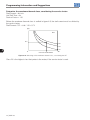
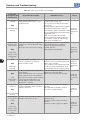
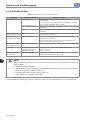
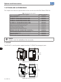
1
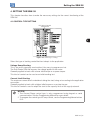
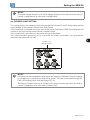
Motors | Automation | Energy | Transmission & Distribution | Coatings Soft-Starter Arrancador Suave Soft-Starter SSW-08 User's Manual Manual del Usuario Manual do Usuário Soft-Starter User’s Guide Manual del Usuario del Arrancador Suave Manual do Usuário da Soft-Starter Serie: SSW-08 English / Español / Português Document: 10000008521 / 03 Date/Data: 03/2011 Summary of revisions / Sumario de las revisiones / Sumário das revisões The information below describes the revisions in this manual. Revision 1 2 3 Description First Edition Size 4 included Revision after the size 4 UL certification. Changed: item 3.2; figure 3.4; figure 3.5; item 3.2.4.1; 3.2.4.2; 3.2.7; 3.3; 5.2.2; E77 in the table 6.1; table 8.1. Included new functions of software version V1.4x. Chapter 3, 4, 5, 6, 8 La información abajo describe las revisiones ocurridas em este manual. Revisión 1 2 3 Descripción Primer Edición Inclusión Mecánica 4 Corrección luego de la certificación UL de la mecánica 4. Modificado: item 3.2; figura 3.4; figura 3.5; item 3.2.4.1; 3.2.4.2; 3.2.7; 3.3; 5.2.2; E77 en la tabla 6.1; tabla 8.1. Inclusión de las nuevas funciones de la version de software V1.4x. Capítulo 3, 4, 5, 6, 8 As informações abaixo descrevem as revisões ocorridas neste manual. Revisão 1 2 3 Descrição Primeira Edição Inclusão da mecânica 4 Correção depois da certificação UL da mecânica 4. Alterado: item 3.2; figura 3.4; figura 3.5; item 3.2.4.1; 3.2.4.2; 3.2.7; 3.3; 5.2.2; E77 na tabela 6.1; tabela 8.1. Inclusão das novas funções da versão de software V1.4x. Capítulo 3, 4, 5, 6, 8 Summary 1. SAFETY INSTRUCTIONS 1.1 SAFETY NOTICES IN THE MANUAL.................................................................................................1 1.2 SAFETY NOTICES ON THE PRODUCT.............................................................................................1 1.3 PRELIMINARY RECOMMENDATIONS..............................................................................................1 2. GENERAL INFORMATION 2.1 ABOUT THIS MANUAL.......................................................................................................................3 2.2 ABOUT THE SOFT-STARTER SSW-08.............................................................................................3 2.3 SOFT-STARTER SSW-08 IDENTIFICATION PLATE ........................................................................5 2.4 RECEIVING AND STORAGE..............................................................................................................7 3. INSTALLATION AND CONNECTION 3.1 MECHANICAL INSTALLATION..........................................................................................................8 3.1.1 Environmental Conditions.........................................................................................................8 3.1.2 Soft-Starter SSW-08 Dimensions............................................................................................8 3.1.3 Mounting Specifications...........................................................................................................9 3.1.3.1 Mounting Inside a Panel............................................................................................. 10 3.1.3.2 Mounting on Surface.................................................................................................. 11 3.2 ELECTRICAL INSTALLATION.......................................................................................................... 11 3.2.1 Power Terminals...................................................................................................................... 12 3.2.2 Location of the Grounding, Control and Power Connections........................................... 13 3.2.3 Recommended Power and Grounding Cables.................................................................... 13 3.2.4 Power Supply Connection to the Soft-Starter SSW-08...................................................... 14 3.2.4.1 Power Supply Capacity.............................................................................................. 15 3.2.4.2 Recommended Fuses................................................................................................. 15 3.2.4.3 Recommended Contactors....................................................................................... 16 3.2.5 Soft-Starter SSW-08 Connection to the Motor................................................................... 16 3.2.5.1 Standard Three-Wire Connection............................................................................. 17 3.2.6 Grounding Connections......................................................................................................... 17 3.2.7 Control and Signal Connections........................................................................................... 19 3.3 RECOMMENDED SET-UPS.............................................................................................................20 3.3.1 Recommended Set-up with Command via Two-wire Digital Inputs and Isolation Contactor...........................................................................................................................21 3.3.2 Recommended Set-up with Command via Three-wire Digital Inputs and .....................21 Circuit-Breaker.................................................................................................................................21 3.3.3 Recommended Set-up with Command via Two-wire Digital Inputs and Direction of Rotation........................................................................................................................22 3.3.4 Recommended Set-up with Command via Two-wires Digital Inputs and DC-Braking..23 3.3.5 Symbols....................................................................................................................................24 4. SETTING THE SSW-08 4.1 CONTROL TYPE SETTING...............................................................................................................25 4.2 KICK START......................................................................................................................................26 4.3 INITIAL VOLTAGE SETTING.............................................................................................................26 4.4 CURRENT LIMIT SETTING..............................................................................................................27 4.5 ACCELERATION RAMP TIME SETTING.........................................................................................28 4.6 DECELERATION RAMP TIME SETTING.........................................................................................28 4.7 MOTOR CURRENT SETTING...........................................................................................................29 4.8 MOTOR ELECTRONIC OVERLOAD PROTECTION........................................................................30 4.9 RESET................................................................................................................................................32 4.10 DI2 DIGITAL INPUT SETTING........................................................................................................32 4.11 OUTPUT RELAY OPERATION........................................................................................................33 4.12 RELAY OUTPUT RL1 PROGRAMMING.........................................................................................33 Summary 5. PROGRAMMING INFORMATION AND SUGGESTIONS 5.1 APPLICATIONS AND PROGRAMMING...........................................................................................34 5.1.1 Voltage Ramp Starting............................................................................................................35 5.1.2 Current Limit Starting.............................................................................................................36 5.1.3 Starting with Pump Control (P202 = 2)..................................................................................36 5.1.4 Programming the control type in pump control..................................................................38 5.2 PROTECTIONS AND PROGRAMMING...........................................................................................38 5.2.1 Suggestion on How to Program the Thermal Class............................................................38 5.2.2 Service Factor......................................................................................................................... 41 6. SOLUTION AND TROUBLESHOOTING 6.1 FAULTS AND POSSIBLE CAUSES...................................................................................................43 6.2 TROUBLESHOOTING.......................................................................................................................46 6.3 PREVENTIVE MAINTENANCE......................................................................................................... 47 7. OPTIONS AND ACCESSORIES 7.1 IP20 KIT..............................................................................................................................................48 8. TECHNICAL CHARACTERISTICS 8.1 NOMINAL POWERS AND CURRENTS ACCORDING TO UL508..................................................49 8.2 NOMINAL POWERS AND CURRENTS FOR STANDARD IP55, IV POLE WEG MOTOR.............49 8.3 POWER DATA....................................................................................................................................50 8.4 ELECTRONICS AND PROGRAMMING DATA.................................................................................50 Safety Instructions 1. SAFETY INSTRUCTIONS 1 This Manual contains the necessary information for the correct use of the Soft-Starter SSW-08. It was written to be used by qualified personnel with suitable training or technical qualifications to operate this type of equipment. 1.1 SAFETY NOTICES IN THE MANUAL The following safety notices will be used in the text. DANGER! Failure to observe the recommended procedures may lead to serious or fatal injuries and considerable material damage. ATTENTION! Failure to observe the recommended procedures in this notice may lead to material damage. NOTE! Important information for the correct understanding and good function of the product. 1.2 SAFETY NOTICES ON THE PRODUCT The following symbols may be attached to the product as a safety notice. High Voltages. Components are sensitive to electrostatic discharge. Do not touch them. Mandatory connection to ground protection (PE). 1.3 PRELIMINARY RECOMMENDATIONS DANGER! Only personnel with suitable qualification and familiar with the Soft-Starter SSW-08 and associated equipment should plan or implement the installation, start-up, operation and maintenance of this equipment. These personnel must follow all safety instructions in this manual and/ or defined by local regulations. Failure to follow these safety instructions may result in personnel injury and/or equipment damage. SSW-08 | 1 Safety Instructions 1 NOTE! In this Manual, qualified personnel are those trained to: 1. Install, ground, power-up, and operate the Soft-Starter SSW-08 according to this manual and the required safety procedures; 2. Use protection equipment according to established regulations; 3. Give First Aid. DANGER! Always disconnect the general power supply before touching any electrical component associated to the Soft-Starter SSW-08. High voltage may be present even after the power supply is disconnected. Wait at least 3 minutes for the total discharge of the capacitors. Always connect the equipment’s heatsink to the protection ground (PE), at the proper connection point. ATTENTION! All electronic boards have components that are sensitive to electrostatic discharges. Do not touch these components or connectors directly. If necessary, first touch the grounded metallic heatsink or use a suitable grounded wrist strap. Do not apply any high voltage test on the Soft-Starter SSW-08! If necessary, contact the manufacturer. NOTE! Soft-Starters SSW-08 may interfere with other electronic equipment. Follow the measures in Chapter 3 to reduce these effects. NOTE! Read this manual completely before installing or operating the Soft-Starter SSW-08. 2 | SSW-08 General Information 2. GENERAL INFORMATION 2.1 ABOUT THIS MANUAL This manual presents the Soft-Starter installation, how to start it up, its main technical characteristics and how to identify and correct the most common problems. The manuals listed next must be consulted in order to get more information regarding the functions, accessories and working conditions: Programming Manual, with a detailed description of the parameters and its functions; RS232 / RS485 Communication Manual. These manuals are supplied in electronic format on the CD-ROM that accompanies the Soft-Starter, or can be obtained at WEG’s web site: http://www.weg.net. 2.2 ABOUT THE SOFT-STARTER SSW-08 The Soft-Starter SSW-08 is a high performance product with 2 phases controled that permits the start control of the three phase AC induction motors. Thus, it prevents mechanical shocks on the load and current peaks in the supply line. The SSW-08 electronic Soft-Starter has been designed to drive three-phase induction motors applied to light duty loads, such as centrifugal pumps, small fans and screw compressors. If the Soft-Starter shall be applied on heavy duty loads, please contact WEG. Three-phase Power Supply DIP Switch for Soft-Starter adjustmente and protection enabling Trimpots to adjust Status Indication LEDs of the SSW-08 DIP switch to adjust the Thermal Class Lid for optional Plug-in Modules Electronic Power Supply (A1 and A2)/ Start/Stop Command of the Motor (D1) and Reset (DI2 and DI3) Relay Output (13, 14/23 and 24) Motor Output Figure 2.1: Frontal view of the SSW-08 SSW-08 | 3 2 General Information R Three-Phase Power Supply S T Control Power Supply A1 A2 Programmable Programmable Digital Digital Inputs Outputs 13 14/23 Dl1 24 Dl2 Dl3 2 RL2 RL1 2x Digital Signal Processor DSP 2x U V W PE Three-Phase Motor Figure 2.2.1: Soft-Starter SSW-08 size 1,2 and 3 block diagram Three-Phase Power Supply R S Control Power Supply T A2 A1 Programmable Digital Inputs Dl1 Dl2 Dl3 Programmable Digital Outputs 13 14/23 RL1 2x 2x U V Digital Signal Processor DSP W Three-Phase Motor PE Figure 2.2.2: Soft-Starter SSW-08 Size 4 block diagram 4 | SSW-08 24 RL2 General Information 2.3 SOFT-STARTER SSW-08 IDENTIFICATION PLATE Serial Number SSW-08 Model WEG Stock Item Number Software Version 2 Input Data (Voltage, Number of Phases, Current and Frequency) Control Power Supply Data (Voltage, Frequency) Manufacturing date (14 corresponds to week and H to year) Figure 2.3: Soft-Starter SSW-08 identification plate Position of the Identification Plate on the Soft-Starter SSW-08: FRONTAL VIEW X VIEW X Figure 2.4: Detail of the Soft-Starter SSW-08 identification plate SSW-08 | 5 6 | SSW-08 0017 = 17 A 0024 = 24 A 0030 = 30 A 0045 = 45 A 0061 = 61 A 0085 = 85 A 0130 = 130 A 0171 = 171 A 0200 = 200 A 0255 = 255 A 0312 = 312 A 0365 = 365 A 0412 = 412 A 0017 SSW-08 Nominal Current T Three-Phase Power Supply 5 220-575 Vac S Optional: S = Standard O = with Optional Blank = Standard IP=IP20 (1) __ Degree of Protection Blank = Standard H1=Electronics supply: 110 to 130 Vac (2) H2= Electronics supply: 208 to 240 Vac (2) __ Special Hardware Blank = Standard __ Special Software Z End of Code The standard product as defined by this code is described as: Degree of Protection: IP20 from 17 A to 85 A and IP00 from 130 A to 412 A. If there is any optional, the fields must be filled out in the correct sequence until the code is completed with the letter Z. REMARQUE! The option field (S or O) defines if the Soft-Starter SSW-08 will be a standard version or if it will include any optional. If standard, the code ends here. Always put the letter Z at the end. For example: EXSSW080017T5SZ = Standard Soft-Starter SSW-08 with 17 A and 220 V to 575 V to three-phase input with the User’s Guide in English, Spanish and Portuguese. (2) Only for the 255 to 412A models. (1) Only for models 130 A to 412 A. BR = Brazil EX = Export SSW08 WEG Soft-Starter Series SSW-08 2 EX Market/Manual HOW TO SPECIFY THE SSW-08 MODEL: General Information General Information 2.4 RECEIVING AND STORAGE The Soft-Starter SSW-08 is supplied in a cardboard box. On the outside of the package there is an identification plate which is identical to the one placed on the Soft-Starter SSW-08. To open the package: 1-Put it on a table; 2-Open the package; 3-Take out the Soft-Starter. Check if: The Identification plate of the Soft-Starter SSW-08 matches the model purchased: Damage has occurred during transport. If so, contact the carrier immediately. If the Soft-Starter SSW-08 is not installed immediately, store it in its package in a clean and dry place with temperature between -25 °C (-13 °F) and 65 °C (149 °F). 1 hour at -40 °C (-40 °F) is permitted. Table 2.1: Dimensions of the package in mm (in) SSW-08 Model 17 A 24 A 30 A 45 A 61 A 85 A 130 A 171 A 200 A 255 A 312 A 365 A 412 A Height H mm (in) Width L mm (in) Depth P mm (in) Volume Weight cm3 (in3) kg (lb) 221 (8.70) 180 (7.09) 145 (5.71) 5768 (352.2) 1.65 (3.64) 260 (10.24) 198 (7.80) 245 (9.65) 12613 (770.8) 3.82 (8.42) 356 (14.02) 273 (10.75) 295 (11.61) 28670 (1750) 8.36 (18.43) 415 (16.34) 265 (10.43) 320 (12.6) 35192 (2147) 10.5 (23.2) Figure 2.5: Dimensions of the package SSW-08 | 7 2 Installation and Connection 3. INSTALLATION AND CONNECTION This chapter describes the procedures for the electrical and mechanical installation of the SoftStarter SSW-08. The guidelines and suggestions must be followed for the correct operation of the Soft-Starter SSW-08. 3.1 MECHANICAL INSTALLATION The location of the Soft-Starters SSW-08 is an important factor to assure the correct operation and high product reliability. Avoid: Direct exposure to sunlight, rain, high moisture and sea air ; Exposure to explosive or corrosive gases and liquids; Exposure to excessive vibration, dust or any metallic and/or oil particles in the air. Allowed Environmental Conditions: Surrounding air Temperature: 0 ºC to 55 ºC (32 ºF to 131 ºF) - nominal conditions. Relative air moisture: 5 % to 90 %, with no-condensation. Maximum altitude: 1,000 m (3,300 ft) above sea level - nominal conditions. From, 1,000 m to 4,000 m (3,300 ft to 13,200 ft) above sea level – current reduction of 1 % for each 100 m (330 ft) above 1,000 m (3,300 ft). Pollution degree: 2 (according to the UL508). Normally, only non conductive pollution. Condensation must not cause conduction in the particles in the air. 3.1.2 Soft-Starter SSW-08 Dimensions The external dimensions and mounting holes are shown in figure 3.1 and table 3.1 below. P L H B A D 3 3.1.1 Environmental Conditions C Figure 3.1: SW-08 dimensions 8 | SSW-08 Installation and Connection Table 3.1: Installation data with dimensions in mm (in) SSW-08 Model 17 A 24 A 30 A 45 A 61 A 85 A 130 A 171 A 200 A 255 A 312 A 365 A 412 A Height H mm (in) Width L mm (in) Depth P mm (in) A mm (in) B mm (in) C mm (in) D mm (in) 162 (6.38) 95 (3.74) 157 (6.18) 85 (3.35) 120 (4.72) 5 (0.20) 4 (0.16) M4 1.3 (2.9) IP20 208 (8.19) 144 (5.67) 203 (7.99) 132 (5.2) 148 (5.83) 6 (0.24) 3.4 (0.13) M4 3.3 (7.28) IP20 276 (10.9) 223 (8.78) 220 (8.66) 208 (8.19) 210 (8.27) 7.5 (0.3) 5 (0.2) M5 7.6 (16.8) IP00 * 331 (13.0) 227 (8.94) 242 (9.53) 200 (7.87) 280 (11.0) 15 (0.59) 9 (0.35) 9.2 (20.32) IP00 * Degree Mountin Weight kg of Screw (lb) Protection M8 * IP20 with optional. 3.1.3 Mounting Specifications To install the Soft-Starter SSW-08 leave at least the free spaces surrounding the Soft-Starter as in figure 3.2 below. The dimensions of these free spaces are described in table 3.2. Table 3.2: Recommended free spaces SSW-08 Model 17 A 24 A 30 A 45 A 61 A 85 A 130 A 171 A 200 A 255 A 312 A 365 A 412 A A mm (in) B mm (in) C mm (in) 50 (2) 50 (2) 30 (1.2) 80 (3.2) 80 (3.2) 30 (1.2) 100 (4) 100 (4) 30 (1.2) 150 (6) 150 (6) 30 (1.2) Install the Soft-Starter SSW-08 in the vertical position according to the following recommendations: 1) Install on a reasonably flat surface; 2) Do not put heat sensitive components immediately above the Soft-Starter SSW-08. ATTENTION! If a Soft-Starter SSW-08 is installed on top of another use the minimum distance A + B and diverge from the top Soft-Starter the hot air that comes from the one beneath it. ATTENTION! Independent conduits or cable trays must be planned for physic separation of signal, control and power cables. (Refer to item 3.2 Electric Installation). SSW-08 | 9 3 Installation and Connection A Air Flow Outlet 3 C Air Flow Inlet B Figure 3.2: Free spaces for ventilation 3.1.3.1 Mounting Inside a Panel For Soft-Starters SSW-08 installed in panels or closed metallic boxes exhaustion/cooling is required so the temperature does not exceed the maximum allowed. Refer to dissipated nominal power in table 3.3. Table 3.3: Dissipated power for ventilator panel dimensioning 10 | SSW-08 SSW-08 Model Dissipated Power in the electronics (W) Average Power dissipated 10 starts/h 3 x In @ 20 s (W) 17 A 24 A 30 A 45 A 61 A 85 A 130 A 171 A 200 A 255 A 312 A 365 A 412 A 12 12 12 12 12 12 12 12 12 36 36 36 36 6.8 9.6 12 18 24.4 34 52 68.4 80 102 125 146 165 Total Average Power dissipated 10 starts/h 3 x In @ 20 s (W) 18.8 21.6 24 30 36.4 46 64 80.4 92 138 161 182 201 Installation and Connection 3.1.3.2 Mounting on Surface Figure 3.3 shows the installation of the Soft-Starter SSW-08 on the surface of a mounting plate. 3 Figure 3.3: Installation procedures of the Soft-Starter SSW-08 on a surface 3.2 ELECTRICAL INSTALLATION DANGER! The Soft-Starter SSW-08 cannot be used as an emergency stop device. Always use an isolation contactor or a circuit breaker to disconnect the power supply of the SSW-08. DANGER! Be sure that the AC input power is disconnected before making any terminal connection. ATTENTION! The information below may be used as a guide to achieve a proper installation. Follow also the applicable local standards for electrical installations. ATTENTION! If a power isolating contactor or circuit breaker with minimum voltage coil is not used at the first power on, then power up the electronics first, adjust the trimpots that are necessary to put the SSW-08 into operation and only after this energize the power section. SSW-08 | 11 Installation and Connection Circuit-breaker T S R Fuses R/1L1 S/3L2 T/5L3 Line 3 U/2T1 V/4T2 W/6T3 PE PE PE Figure 3.4: Standard power/grounding connections 3.2.1 Power Terminals The power connection terminals can be of different sizes and configurations depending on the Soft-Starter SSW-08 model as shown in figures 3.5 and 3.6. Terminals : R / 1L1, S / 3L2 and T / 5L3: AC supply line. U / 2T1, V / 4T2 and W / 6T3: Motor connection. R/1L1 S/3L2 T/5L3 R/1L1 Output Power Terminal Input Power Terminal V/4T2 Models 130 A to 412 A Figure 3.5: Power terminals 12 | SSW-08 Input Power Terminal Output Power Terminal U/2T1 Models 17 A to 85 A T/5L3 S/3L2 W/6T3 Installation and Connection Table 3.4: Maximum torque for power connection SSW-08 Model Line / Motor Torque Screw/ Nm Terminal (in lb) Enclosure Size 17 A 24 A 30 A 45 A 61 A 85 A 130 A 171 A 200 A 255 A 312 A 365 A 412 A Grounding Torque Screw Nm (in lb) Size 01 Terminal 3 (27) M4 (5/32”) 4.5 (40) Size 02 Terminal 5.5 (49) M5 (3/16”) 6 (53) Size 03 M8 (5/16”) 19 (168) M6 (1/4”) 8.3 (73) Size 04 M10 (3/8”) 37 (328) Terminal 0.5 (4.5) 3 3.2.2 Location of the Grounding, Control and Power Connections Control Grounding C O N TR O L E Control A TER R A M EN TO C O N TR O L E Control C O N TR O L E 25.1 (0.99) 39.7 (1.56) Control C O N TR O L E 48.2 (1.90) 33.0 (1.30) 32.7 (1.29) 39.0 (1.54) 63.0 (2.48) 22.7 (0.89) 13.3 (0.52) 62.8 (2.48) 56.3 (2.22) 36.3 (1.43) A TER R A M EN TO A TER R A M EN TO Grounding Grounding 197 (7.75) 148 (5.81) 114 (4.48) 84,8 (3.34) 75.5 (2.97) 63.0 (2.48) 39.0 (1.54) 14.8 14.8 (0.59) (0.59) 75.5 (2.97) 60.5 (2.38) A TER R A M EN TO Grounding Dimensions in mm (in). Figure 3.6: Location of the grounding, control and power connections 3.2.3 Recommended Power and Grounding Cables The described specifications in table 3.5 are valid only for the following conditions: Copper wires for 70 ºC (158 ºF) with PVC insulation for ambient temperature of 40 ºC (104 ºF), installed in perforated and not agglomerated conduits. Naked or silver coated copper busbars with round edges with 1 mm radius with ambient temperature of 40 ºC (104 ºF) and bus temperature of 80 °C (176 °F). NOTE! For correct cable dimensioning, consider the installation condition and the maximum permitted line voltage drop. SSW-08 | 13 Installation and Connection Table 3.5: Minimum cable gauge specification SSW-08 Model 17 A 24 A 30 A 45 A 61 A 85 A 130 A 171 A 200 A 255 A 312 A 365 A 412 A 3 Power Cable AWG (mm2) 2.5 14 4 12 6 10 10 8 16 6 25 3 50 1/0 70 2/0 95 4/0 120 250 kcmil 185 400 kcmil 240 500 kcmil 240 600 kcmil Grounding Cable (mm2) AWG 4 12 6 10 6 10 6 10 10 8 10 8 25 3 35 2 50 1/0 2.5 14 2.5 14 2.5 14 2.5 14 3.2.4 Power Supply Connection to the Soft-Starter SSW-08 DANGER! The AC input must be compatible with the voltage range of the Soft-Starter SSW-08. DANGER! Provide a power supply disconnecting switch for the Soft-Starter SSW-08. This disconnecting switch must disconnect the AC input voltage to the Soft-Starter SSW-08 whenever necessary (for example: during maintenance services). If a disconnected switch or a contactor is inserted in the motor supply line never operate these devices with the motor running or when the Soft-Starter SSW-08 is enabled. ATTENTION! Over-voltage control in the line that supplies the Soft-Starter must be made using overvoltage protections of 680 Vac (phase to phase connection) and energy absorption capacity of 40 joules (17 A to 200 A models) and 80 joules (255 A to 412 A models). NOTE! Use the wire sizes and fuses recommended in tables 3.5, 3.6 and 3.7. The connector tightening torque is indicated in table 3.4. Use only copper wires 70 °C (158 °F). 14 | SSW-08 Installation and Connection 3.2.4.1 Power Supply Capacity The Soft-Starter SSW-08 is suitable to be used in a circuit capable of supplying not more than X (according to table 3.6) symmetrical rms amperes, Y maximum volts when protected by ultrarapid fuses. Table 3.6: Maximum current capacity of the Power supply SSW-08 Model 17 A 24 A 30 A 45 A 61 A 85 A 130 A 171 A 200 A 255 A 312 A 365 A 412 A Y = 220-575 V X (kA) 5 5 5 5 5 10 10 10 10 25 25 25 25 3 The SSW-08 can be installed on power supplies with a higher fault level, if it is protected by ultra-rapid fuses with an adequate interrupting current and an I2t according to item 3.2.4.2. 3.2.4.2 Recommended Fuses High speed fuses must be used at the input, wich will protect the SSW-08 against short circuit. It is possible to use other protection devices that will protect the installation; however, in that case the SSW-08 will remain unprotected. The fuse rated current should preferably be equal or greater the motor starting current to avoid cyclic overloads and fuse opening in the forbidden region of the Time x Current curve. Table 3.7: Recommended fuses SSW-08 Model 17 A 24 A 30 A 45 A 61 A 85 A 130 A 171 A 200 A 255 A 312 A 365 A 412 A Nominal Current (A) 50 80 80 100 125 200 315 450 500 500 630 630 700 Maximum I2 t (103 x A 2s) 0.72 4 4 8 10.5 51.2 97 168 245 90 238 238 320 UL Fuses Ferraz Shawmunt/ Cooper Mersen Bussmann 6.6URD30TTF0050 170M2611 6.6URD30TTF0080 170M1366 6.6URD30TTF0080 170M1366 6.6URD30TTF0100 170M1367 6.6URD30TTF0125 170M1368 6.6URD30TTF0200 170M1370 6.6URD31TTF0325 170M1372 6.6URD32TTF0450 170M3170 6.6URD33TTF0500 170M3171 6.6URD33TTF0500 170M3171 6.6URD33TTF0630 170M3173 6.6URD33TTF0630 170M3173 6.6URD33TTF0700 170M6161 WEG Fuses 10806688 10705995 10707110 10701724 10809489 10711445 10824053 10824109 10824110 10833056 10833591 - Control Fuses 2A (D Type) or 2A Circuit Breakers (C Type) NOTE! The maximum I2t of the SSW-08 255A fuse is smaller than 200A because of the thyristor constructive type used on this soft-starter. SSW-08 | 15 Installation and Connection 3.2.4.3 Recommended Contactors When the SSW08 is used in applications that require an isolator contactor, according to the figure 3.10 (K1), the use of WEG contactors is recommended. Table 3.8: Recommended contactors SSW-08 Model 17 A 24 A 30 A 45 A 61 A 85 A 130 A 171 A 200 A 255 A 312 A 365 A 412 A 3 WEG Contactor CWM18 CWM25 CWM32 CWM50 CWM65 CWM95 CWM150 CWM180 CWM250 CWM250 CWM300 CWME400 CWME400 3.2.5 Soft-Starter SSW-08 Connection to the Motor DANGER! Power factor correction capacitors must never be installed at the output of the Soft-Starter SSW-08. (U / 2T1, V / 4T2 and W / 6T3). ATTENTION! To ensure that the protections based on the current reading and display operate correctly, for example the overload, the motor nominal current must not be lower than 50 % of the nominal Soft-Starter SSW-08 current. NOTE! Use the wire sizes and fuses recommended in tables 3.5, 3.6 and 3.7. The connector tightening torque is indicated in table 3.4. Use only copper wires. NOTE! The Soft-Starter SSW-08 is provided with electronic protection against motor overload. This protection must be set according to the specific motor. When several motors are connected to the same Soft-Starter SSW-08 use individual overload relays for each motor. 16 | SSW-08 Installation and Connection 3.2.5.1 Standard Three-Wire Connection Line current of the Soft-Starter SSW-08 is equal to the motor current. R S T N PE R S T N PE R S T V U R W T S V U W 2/V1 4/U2 1/U1 6/W2 2/V1 3/W1 4/U2 5/V2 6/W2 1/U1 3/W1 3 5/V2 Figure 3.7: Soft-Starter SSW-08 with standard connection 3.2.6 Grounding Connections DANGER! The Soft-Starter must be grounded for safety purposes (PE). The ground connection must comply with the local regulations. For grounding use cables with cross sections as indicated in table 3.5. Make the ground connection to a grounding bar or to the general grounding point (resistance ≤10 ohms). DANGER! The AC input for the Soft-Starter SSW-08 must have a ground connection. DANGER! Do not use the neutral conductor for grounding purpose. Use dedicated ground conductor. ATTENTION! Do not share the ground wiring with other equipment that operate with high current (for examples: high voltage motors, welding machines, etc.). When several Soft-Starters SSW-08 are used, observe the connections in the figure 3.8. SSW-08 | 17 Installation and Connection Grounding bar internal to the panel 3 Grounding bar internal to the panel Figure 3.8: Grounding connections for more than one Soft-Starter SSW-08 EMI - Electronic Interference The Soft-Starter SSW-08 is developed to be used in industrial systems (Class A) according to Standard EN60947-4-2. It’s necessary to have a distance of 0.25 m (10 in) between the Soft-Starter SSW-08 and the cables between the Soft-Starter SSW-08 and the motor. Example: CLP wiring, temperature controllers, thermocouple cables, etc. Grounding of the Motor frame Always ground the motor frame. Ground the motor in a panel where the Soft-Starter SSW-08 is installed. The Soft-Starter SSW-08 output wiring to the motor must be installed separately from the input wiring as well as from the control and signal wiring. CORRECT CORRECT ATTENTION! Only the motor frame shall be grounded. 18 | SSW-08 INCORRECT INCORRECT Installation and Connection 3.2.7 Control and Signal Connections The control connections (digital inputs and relay outputs) are made through the terminals (refer to figure 3.9). Table 3.9: Description of the control connector pins Terminal Description Electronics Supply Voltage: 110 to 240 Vac (-15 % to +10 %) (models from 17 A to 200 A) 110 to 130 Vac or 208 to 240 Vac (-15 % to 10 %) (models from 255 A to 412 A). Grounding Only for the 255 to 412 A models Factory Default Starts/Stops Motor Fault reset Fault reset Relay 1 output - Operation Relay common point Relay 2 output - Full voltage Specifications 3 isolated digital inputs Voltage: 110 to 240 Vac (-15 % to +10 %) Current: 2 mA Max. Contact capacity: Voltage: 250 Vac Current: 1 A A1 A2 Terminal DI1 DI2 DI3 13 14/23 24 Specifications Torque Nm (in lb) 3 0.5 (4.5) Figure 3.9: Control terminals of the Soft-Starter SSW-08 NOTE! It is recommended to use shielded cables for the Dix inputs when using long cables (above 30m) in noisy enviroments. The metallic shield and A2 must be grounded. SSW-08 | 19 Installation and Connection 3.3 RECOMMENDED SET-UPS Some recommended set-ups are shown here and they can be completely or partly used. The main warning notes for all the recommended set-ups are shown below and are described in the schemes by their respective numbers. 3 NOTE! 1 For the protection of the whole electrical installation it is necessary to use fuses or circuit breakers. The use of ultra-rapid fuses is not required for the operation of the Soft-Starter SSW-08 but they are recommended for the complete SCR protection. 2 The transformer “T1” is optional and must be used when there is a difference between the line voltage and the electronic power voltage. 3 To protect the motor from damage by possible short-circuits in the power circuit of the Soft-Starter SSW-08 use an isolating contactor (K1) or circuit-breaker (Q1). 4 Start push-button. 5 Stop push-button. 6 Start/Stop switch, remember that when the command via two-wire digital input is used (the switch is normally open with retention) every time the power supply is restored after any fault the motor will start immediately if the switch remains closed. 7 In case of maintenance of the Soft-Starter SSW-08 or the motor it is necessary to remove the input fuses or disconnect the power supply to ensure the complete equipment disconnection from the power supply. 8 The emergency stop can be used by disconnecting the electronics power supply. 9 Undervoltage release for the Q1 power isolation circuit breaker. 20 | SSW-08 Installation and Connection 3.3.1 Recommended Set-up with Command via Two-wire Digital Inputs and Isolation Contactor T1 R S T PE K1 K1 3 R ST A1 A2 DI1 DI2 DI3 13 14 23 RL1 24 RL2 Refer to notes in item 3.3. U VW M 3~ Figure 3.10: Recommended set-up with commands via two-wire digital inputs and isolation contactor 3.3.2 Recommended Set-up with Command via Three-wire Digital Inputs and Circuit-Breaker T1 R S T PE Q1 Q1 R ST A1 A2 DI1 DI2 DI3 13 14 23 RL1 24 RL2 Refer to notes in item 3.3. U VW M 3~ Figure 3.11: Recommended set-up with commands via three-wire digital inputs and a circuit-breaker SSW-08 | 21 Installation and Connection NOTE! It’s necessary to program the digital input DI2 for the three-wire command function. Refer to item 4.10. NOTE! The RL1 shall be set to the “No fault” function. Refer to item 4.12. 3 3.3.3 Recommended Set-up with Command via Two-wire Digital Inputs and Direction of Rotation P220 = 1 P230 = 1 R P263 = 1 (DI1 = Start/Stop two S wires) T P265 = 4 (DI3 = Rotation Direction) P E P277 = 4 (RL1 = FWD/REV - K1) P278 = 4 (RL2 = FWD/REV - K2) T1 K1 K1 K2 K2 R ST A1 A2 DI1 DI2 DI3 13 14 23 RL1 24 RL2 Refer to notes in item 3.3 U VW M 3~ Figure 3.12: Recommended Set-up with Command via Two-wire Digital Inputs and Direction of Rotation NOTE! To program the parameters shown above, is necessary the use of keypad or serial communication. See the Programming Manual for more information. 22 | SSW-08 Installation and Connection 3.3.4 Recommended Set-up with Command via Two-wires Digital Inputs and DCBraking P220 = 1 P230 = 1 P263 = 1 (DI1 = Start/Stop two wires) P265 = 5 (DI3 = Brake Off) P277 = 1 (RL1 = Running) P278 = 5 (RL2 = DC-Braking) P501 ≥ 1 (DC Braking Time ≥ 1s) T1 R S T PE K1 K1 K2 R ST A1 A2 DI1 DI2 DI3 13 14 23 RL1 3 24 RL2 Refer to notes in item 3.3 U VW K2 M 3~ Figure 3.13: Recommended Set-up with Command via Two-wires Digital Inputs and DC-Braking NOTE! To program the parameters shown above, is necessary the use of keypad or serial communication. See the Programming Manual for more information. SSW-08 | 23 Installation and Connection 3.3.5 Symbols Electrical connection between two signals Fuse Connection terminals Thyristor/SCR Relay or contactor coil 3 Three-phase motor  M 3~ Normally open contact (NO) Emergency button Indicator light Transformer Circuit-breaker (opens under load) N.O Contact (with retention) Resistor Normally closed (NC) push-button Capacitor Normally open (NO) push-button Circuit-breaker with undervoltage release 24 | SSW-08 Setting the SSW-08 4. SETTING THE SSW-08 This chapter describes how to make the necessary settings for the correct functioning of the SSW-08. 4.1 CONTROL TYPE SETTING DIP Switch Control Type Setting 4 Figure 4.1: Control type setting Select the type of starting control that best adapts to the application. Voltage Ramp Starting: This is the most commonly used method. Very easy to program and set. The Soft-Starter SSW-08 imposes the voltage applied to the motor. Generally applied to loads with a lower initial torque or a square torque. This kind of control can be used as an initial working test. Current Limit Starting: The maximum current level is maintained during the start, being set according to the application necessities. Generally applied to loads with a higher initial torque or a constant torque. This kind of control is used to adapt the start to the capacity limits of the supply network. NOTES! 1.The Current Ramp control type, is only programmed using keypad or serial communication. See the Programming Manual for more details. 2.To program the control type in Pump control, see the Programming Manual or item 5.1.4. SSW-08 | 25 Setting the SSW-08 4.2 KICK START Kick Start Enabling DIP Switch 4 Figure 4.2: Kick Start enabling Soft-Starter SSW-08 offers a Kick Start function for loads that present a large initial resistance to movement. This function is enabled through the Kick Start DIP Switch. The duration of the voltage pulse is set through the trimpot Kick Start Time. The voltage pulse applied is of 80 % Un during the programmed trimpot Kick Start Time. NOTE! Use this function only for specific applications and where necessary. 4.3 INITIAL VOLTAGE SETTING Set the initial voltage to a value that the motor starts to run as soon as the start command is given to the SSW-08. Initial Voltage Setting Trimpot The dot indicates the factory default setting Figure 4.3: Initial voltage setting 26 | SSW-8 Setting the SSW-08 NOTE! The Initial Voltage trimpot has an initial voltage setting function only when the kind of control is programmed to start with a voltage ramp. 4.4 CURRENT LIMIT SETTING This setting defines the maximum limit of the current from phases R and S during motor starting in percentage of the nominal current of the Soft-Starter. If the current limit is reached during the start of the motor, Soft-Starter SSW-08 will maintain the current at this limit until the motor reaches nominal speed. If the current limit is not reached, the motor will start immediately. The current limitation should be set to a level that the motor acceleration can be observed, otherwise the motor will not start. Current Limit Setting Trimpot Figure 4.4: Current limit setting NOTE! If at the end of the acceleration ramp (set at the Trimpot Acceleration Time), full voltage is not reached, a start timeout Fault will be shown. This fault is indicated through the Fault LED flashing twice with the Ready LED on. The trimpot Current Limit has a Current Limit setting function only when the kind of control is programmed to start with a Current Limit. SSW-08 | 27 4 Setting the SSW-08 4.5 ACCELERATION RAMP TIME SETTING When Soft-Starter SSW-08 is programmed to Voltage Ramp control, this is the voltage increment ramp time. When Soft-Starter SSW-08 is programmed to Current Limit control, this time is used as the maximum starting time, working as a protection against blocked rotors. Acceleration Ramp Time Setting Trimpot 4 Figure 4.5: Acceleration ramp time setting NOTE! The programmed acceleration time is not the exact motor acceleration time, but the time of the voltage ramp or the maximum starting time. The motor acceleration time depends on the motor characteristics and the load. Please consider that in cases where the relation of the SSW-08 current and the motor nominal current is 1.00, the maximum time that the SSW-08 can work with 3 x In is 20 seconds. 4.6 DECELERATION RAMP TIME SETTING Enables and sets the time of voltage decrease. This setting should be used only for the deceleration of pumps to reduce the water hammer. This setting must be made to achieve the best pump performance. NOTE! This function is used to lengthen the normal deceleration time of a load and not to force a lower time than that imposed by the load itself. Deceleration Ramp Time Setting Trimpot 28 | SSW-8 Figure 4.6: Deceleration ramp time setting Setting the SSW-08 4.7 MOTOR CURRENT SETTING This setting defines the ratio of the SSW-08 current and the motor current. The value of the setting is very important since it defines the protection of the motor driven by the SSW-08. The setting of this function interferes directly in the following motor protections: Overload; Overcurrent; Stall; Phase loss. Calculation Example: SSW-08 Used: 30 A Motor Used: 25 A Trimpot for the Motor Current Setting Motor Current Setting = I motor I SSW-08 25 A Motor Current Setting = 30 A Motor Current Setting = 0.833 4 Therefore it must be set at 83 % Motor Current Setting Trimpot Figure 4.7: Motor current setting SSW-08 | 29 Setting the SSW-08 4.8 MOTOR ELECTRONIC OVERLOAD PROTECTION The motor electronic overload protection simulates the heating and cooling of the motor, also known as thermal image. This simulation uses as input data the True rms current. When the thermal image passes the limit, the overload protection trips and turns the motor off. The adjustment of the thermal class is based on the motor locked rotor current and locked rotor time. With this data it is possible to find a point in the figure to determine, which thermal class protects the motor. Please refer to figure 4.8 for cold stall time or to figure 4.9 for hot stall time. The thermal classes below the point protect the motor. Time t(s) 10000 4 1000 100 10 1 S.F.=1 Class 30 Class 25 Class 20 Class 15 Class 10 1x 2x 3x 4x 5x 6x 7x 8x 9x Class 5 x In motor current S.F.=1,15 1x 2x 3x 4x 5x 6x 7x 8x 9x 10x Figure 4.8: Thermal classes of motor protection in cold condition 30 | SSW-8 Setting the SSW-08 Time t(s) 1000 100 10 4 Class 30 Class 25 Class 20 Class 15 Class 10 1 Class 5 0.1 1x 2x 3x 4x 5x 6x 7x 8x 9x x In motor Current S.F.=1 Figure 4.9: Motor protection thermal classes in hot condition at 100 % ln Overload Protection Enabling DIP Swicth Thermal class adjustment DIP Switches Figure 4.10: Overload protection Enabling and Adjustment SSW-08 | 31 Setting the SSW-08 NOTES! Adjust the motor current according to chapter 4.7 for the correct function of the overload protection; This protection is based on Three Phase IP55 Standard WEG motors. If your motor is different, we recommend to adjusting a lower thermal class. For more details refer to chapter 5.2; When SSW-08 is without the electronic supply voltage (A1 and A2), the thermal image is saved internally. When the supply (A1 and A2) is reestablished, the thermal image returns to the value prior to the electronic supply loss; The RESET of the electronic overload protection can be set to manual function (man). In this case the RESET must be made via digital input 2 (DI2) or through the RESET key. If the RESET setting is automatic (auto), the fault condition will automatically be reset after the cooling time; The thermal image is set to zero, when the overload protection is disabled. 4 4.9 RESET A fault condition can be reset using the RESET key at the front of the SSW-08 or through a push-button (0.5 seconds) at DI3 (digital input for RESET). Another way to reset the SSW-08 is by switching Off/On the electronic power supply (A1 and A2). NOTE! The SSW-08 also allows for the possibility of automatic RESET by enabling this function through the DIP Switch (auto): Automatic RESET occurs after 15 minutes in the following conditions: - Overcurrent; - Phase loss; - Stall; - Overcurrent before By-pass; - Frequency out of range; - Contact of the internal By-pass relay is open; - Power control supply undervoltage; - External fault. For incorrect phase sequence there is no automatic RESET. For electronic overload of the motor there is a specific algorithm for the automatic RESET time. 4.10 DI2 DIGITAL INPUT SETTING In the factory default, the DI2 digital input has its function programmed for the reset of faults. DI2 can also be programmed to work as a three wire control. The three wire control allows the Soft-Starter to be commanded through two digital inputs, DI1 as an ON input and DI2 as an OFF input. This allows for the direct placement of two push buttons. Refer to item 3.3.2. To change the DI2 digital input, follow the instructions below: 1. To enter in programming mode, maintain the reset key at the front of the SSW-08 pressed for 5 seconds. Maintain the reset key pressed during programming; 2. When in programming mode, two LEDs will turn on (overcurrent and phase loss), indicating that DI2 is programmed for fault Reset. When three LEDs turn on (overcurrent, phase loss and phase sequence), it indicates that the DI2 is programmed for three wire commands; 32 | SSW-8 Setting the SSW-08 3.To change the programming to three wire commands, move the overcurrent DIP Switch and return to the previous position. The three LEDs will turn on, indicating that DI2 is programmed for three wire commands; 4. To change the DI2 programming to fault Reset, move the Kick Start DIP Switch and return to the previous position. Two LEDs will turn on, indicating that the DI2 is programmed for fault Reset; 5.Programming is concluded when the reset key is released. 4.11 OUTPUT RELAY OPERATION The relay of the Operation Function closes its N.O. contact (13-14/23) every time the SSW-08 receives the enable command. This contact is only opened at the end of the deceleration ramp (when it is set via trimpot) or when the SSW-08 receives the disable command. The relay of the Full Voltage Function closes the N.O. contacts (14/23-24) every time the SSW-08 applies 100 % of the voltage to the driven motor. This contact opens when the SSW-08 receives the disable command. UN (Motor Voltage) 100 % t Operation Function (13- 14/23) t Full Voltage Function (14/23-24) t Relay on Figure 4.10: Output relay operation 4.12 RELAY OUTPUT RL1 PROGRAMMING In the factory default programming, the relay output RL1 has its function programmed for “Operation”. RL1 (13/14) can be also be programmed for the “No Fault” function. This function allows the installation of a circuit breaker with an undervoltage release at the SSW-08 input. Refer to figure 3.3.2. In order to change the relay output RL1 programming follow these instructions: 1. To enter in programming mode keep the reset key, at the SSW-08 front cover, pressed during 5 seconds, keeping it also pressed throughout the programming; 2. When in the programming mode two LEDs turn on (Overcurrent and Phase Loss), indicating that DI2 is programmed for Error Reset. If three LEDs turn on (Overcurrent, Phase Loss and Phase Sequence), it indicates that DI2 is programmed for three-wire command. If the Overload LED turns on, then the RL1 function is “No Fault”, otherwise the function is “Operation”; 3.To modify the RL1 function change the Overload DIP Switch and put it back in the previous position. The Overload LED will indicate the new programmed function: - Overload LED off: Operation function; - Overload LED on: No Fault function. SSW-08 | 33 4 Programming Information and Suggestions 5. PROGRAMMING INFORMATION AND SUGGESTIONS This chapter helps the user to set the types of starting controls according to their applications. 5.1 APPLICATIONS AND PROGRAMMING ATTENTION! Suggestions and important notes for each type of starting control. ATTENTION! To know the correct programming of the parameters, have your load data on hand and use the WEG (Soft-Starter) Dimensioning Software available at WEG’s home page (http://www.weg.net). If you are unable to use the software mentioned above, you can follow some practical concepts described in this chapter. 5 Shown below are some characteristic curves with current and starting torque behavior according to some kinds of control. I/In T/Tn Current Torque Tn I/In T/Tn Tn Current Torque Figure 5.1: Characteristic curves of torque and current in a direct on-line start and by voltage ramp 34 | SSW-08 Programming Information and Suggestions I/In T/Tn Current Tn Torque Figure 5.2: Characteristic curves of torque and current in a current limitation start The following items show characteristic curves with the starting torque behavior according to some types of loads and their suggested controls. 5.1.1 Voltage Ramp Starting 1) Set the value of the initial voltage to a low value; 2) When a load is applied to the motor, set the initial voltage to a value that makes the motor rotate smoothly from the instant it is started. 3) Set the acceleration time with the necessary start time, initially with short times, 10 to 15 seconds, and afterwards try to find the best starting condition for the used load. U(V) Start 100 %Un 0 t(s) Enable Voltage Ramp Disable Figure 5.3: Voltage ramp starting NOTE! With long starting times, or when the motor is without a load, vibration can occur during the start of the motor, therefore lower the starting time; If faults occur during the start, check all the connections from the Soft-Starter to the supply network, motor connections, supply network voltage levels, fuses and circuit breakers. SSW-08 | 35 5 Programming Information and Suggestions 5.1.2 Current Limit Starting 1) To start with a current limitation it is necessary to start with a load. Initial test without load can be done with a voltage ramp; 2) Set the acceleration time with the necessary starting time, initially with short times, 15 to 20 seconds. This time will be used as the stall time in case the motor does not start; 3) Set the current limit according to the conditions that your electric installation allows, as well as to the values that supply enough torque to start the motor. It can initially be programmed with values between 2x and 3x the nominal current of the motor (ln of the motor). I(A) Start I Limitation I Nominal Maximum Time 5 0 t(s) Enable Current Limitation Disable Figure 5.4: Current limit starting NOTE! If the current limit is not reached during the start, the motor will start immediately; Very low Current Limit values do not provide sufficient torque to start the motor. Always keep the motor rotating once it is started. For loads that need a higher initial starting torque, the Kick Start function can be used; If faults occur during the start, check all the connections from the Soft-Starter to the supply network, motor connections, supply network voltage levels, fuses and circuit breakers. 5.1.3 Starting with Pump Control (P202 = 2) 1) To start with pump control a load is necessary. No-load tests can be done with voltage ramp; 2) The starting parameters setting depend mainly on the types of hydraulic installations. Thus we recommend optimizing factory settings, if possible. 3) Check if the motor rotation direction is an indicated on the pump frame. If not, connect the phase sequence as indicated at P620; Figure 5.5: Direction of rotation of a hydraulic centrifugal pump 36 | SSW-08 Programming Information and Suggestions 4) Set the initial voltage - P101 – so the motor starts smoothly as soon as it is enabled. 5) Set the acceleration time according to the application, and, that the motor is able to start the load smoothly, but the required acceleration is not exceeded. If acceleration times are set too long, this may result in vibration or harmful motor overheating; 6) To check the correct starting process, always use a manometer in the hydraulic installation. Pressure increase should not result in sudden oscillations. Thus the pressure increase should be as linear as possible; U(V) Start 100%Un P101 0 P102 Enable Pump Control 5 Figure 5.6: Manometer showing pressure increase 7) Program the deceleration initial voltage (P103) only when no pressure drop is detected at the deceleration begin. With this deceleration initial voltage you can improve the linear pressure drop during the deceleration; 8) Set the deceleration time according to the application, and, ensuring that the pump stops smoothly within the expected limits. The set of excessively long times may result in vibrations or harmful motor overheating; U(V) 100%Un Stop P103 P105 0 P104 t(s) Disable Figure 5.7: Manometer showing the pressure drop 9) Generally, the current increases at the end of the deceleration ramp and in this case the motor requires more torque to achieve a smooth water flow stop. When the motor has already stopped, but is still enabled, the current will increase too much. To prevent this condition, set P105 to a value that as soon it stop it is also disabled; 10)Set P610 and P611 to current and time levels that prevent the hydraulic pump from running without a load. SSW-08 | 37 Programming Information and Suggestions U(V) Stop 100%Un Start P103 P101 0 P105 P102 Enable Pump Control P104 t(s) Disable Figure 5.8: Start with pump control 5 NOTES! 1.If the hydraulic piping is not fitted with a manometer, the water hammer can be noted at the pressure relief valves; 2.Please, consider that sudden line voltage drops results in motor torque drops. Thus, ensure that the power supply line characteristics are within the characteristics required for motor operation; 3.If errors are detected during the motor start, check all connections of the Soft-Starter to the power line, the motor connections, the voltage levels of the power line, the fuses, circuit-breakers and disconnecting switches. 5.1.4 Programming the control type in pump control Is recommended program the control type in pump control using keypad or serial communication, see the Programming Manual for more details. In special cases, when is not available keypad or serial communication, is also possible to program the control type in pump control following these instructions: 1) To enter in programming mode, keep the reset key at the SSW-08 front cover pressed during 5 seconds, keeping it also pressed throughout the programming; 2) When in the programming mode, LEDs will turn on indicating the actual parameterization. See item 4.10 and 4.12; 3) To modify the control type, change the Stall DIP Switch and put it back in the previous position. The Stall LED will indicate the new programmed control type: - LED Stall off: P219=0. Control type defined through Voltage Ramp/Current Limit DIP Switch. - LED Stall on: P219=2. Control type in Pump Control and parameterization through Trimpots and DIP Switches. 5.2 PROTECTIONS AND PROGRAMMING 5.2.1 Suggestion on How to Program the Thermal Class For each application exists a range of thermal classes, which might be set. The overload protection should not trip during normal starting. Therefore it is necessary to know the starting time and current, to determine the minimum thermal class. The maximum thermal class depends on the motor limit. 38 | SSW-08 Programming Information and Suggestions Determine the minimum thermal class: 1) Initially start at the standard thermal class, sometimes, but without the motor overheating; 2) Determine the correct starting time and find an average of the current using a multimeter with a current probe to measure it; A current average can be found for any type of starting control; For example: Starting an 80 A motor using a voltage ramp. The current starts at 100 A and goes to 300 A, returning afterwards to the nominal value in 20 seconds. (100 A + 300 A)/2 = 200 A 200 A/80 A = 2.5 x ln of the motor Therefore: 2.5 x ln @ 20 seconds. U(V) Start 100 % Un 300 A Initial Voltage P101 Motor Current 100 A 5 0 Enable P102 Accel Time 20 s t(s) Figure 5.9: Typical current curve during a voltage ramp start 3) Use this time to find the minimum class necessary to start the motor in cold condition. In the item 4.8 Overload Protection it is possible to check the thermal class curves of the motor in cold condition. t(s) Cold F.S.=1 20 s 15 10 0 2.5 x ln of the motor 5 xln Figure 5.10: Checking the minimum class of curves in cold condition Therefore the minimum class necessary to start the cold motor is Class 10. Class 5 will trip during starting. NOTE! If the motor must start in the hot condition, class 10 will trip during the second start. In the case a higher thermal class must be set. SSW-08 | 39 Programming Information and Suggestions Determine the maximum thermal class: To correctly program the Thermal Class that will protect your motor it is essential to have in hand the motor locked rotor current and locked rotor time. This information is available in the motor manufacturer’s catalogue. Put these values into figure 4.8, in case of the cold stall time or into figure 4.9, in case of hot stall time. For example: Stall Current = 6,6 x ln Hot Stall Time = 6s t(s) Hot 6s 30 25 5 0 6.6 x ln of the motor 20 xln Figure 5.11: Checking the maximum class of curves in hot condition Class 25 is the highest class that protects the motor. NOTE! Remember that this protection has as a standard the Three Phase IP55 Standard WEG Motor, therefore if your motor is different, then do not program the thermal class to its maximum, instead, program it near its minimum thermal class to start. Example of how setting the thermal class: Motor data: Power: 50 hp Voltage: 380 V Nominal Current (ln): 71 A Service Factor (S.F.): 1.00 lp/ln: 6.6 Stall time: 12 s in hot condition Speed: 1770 rpm 40 | SSW-08 Programming Information and Suggestions Motor + load starting data: Starting by Voltage Ramp, starting current average: 3 x the nominal current of the motor during 17 s (3 x ln @ 17 s). 1) In the graph, figure 4.8 in cold condition, one can see the minimum Thermal Class that will allow the start with a reduced voltage: For 3 x ln of the motor @17 s, the next highest is adopted: Class 10. 2) In the graph, figure 4.9 in hot condition, one can see the maximum Thermal Class that the motor can stand due to the stall time in hot condition: For 6.6 x ln of the motor @ 12 s, the next lowest is adopted. Class 30. One now knows that Thermal Class 10 allows a start and Thermal Class 30 is the maximum limit. Thus, a Thermal Class between the two should be adopted, according to the quantity of starts per hour and the interval of time between Off/On procedures the motor. The closer to Class 10, the more protected the motor will be, the fewer the starts per hour and the greater the interval of time must be between Off/On procedures the motor. The closer to Class 30, the closer it gets to the maximum limit of the motor, thus there can be more starts per hour and lower intervals of time between Off/On procedures the motor. 5 5.2.2 Service Factor When the Service Factor (S.F.) is different from 1.00 and if there is the need to use it in the application, this must be considered in the setting of the overload protection. To avoid tripping of the overload protection, when the service factor is used, the nominal motor current set at the SSW08 must be readjusted. If an acessorie with parameter access is used, the service factor can be set direcly in the P406, avoiding the readjustment of the nominal currrent. Example of readjustment of the nominal current: ISSW08 = 30 A IMOTOR = 25 A S. F. = 1.15 Setting of the Motor Current = IMOTOR x S.F. / ISSW08 = 25 A x 1.15 / 30 A = 96% ATTENTION! The increased motor current has direct impact on the maximum thermal class, that protects the motor, even if the S.F. parameter is set. SSW-08 | 41 Programming Information and Suggestions Determine the maximum thermal class, considering the service factor: Stall Current = 6.6 x ln Hot Stall Time = 6s Service Factor = 1.15 Before the maximum thermal class is verified in figure 4.9, the stall current must be divided by the service factor. Stall Current / S.F. = 6.6 / 1.15 = 5.74 t(s) Hot 6s 25 20 5 0 5.74 x In of the motor 15 xln Figure 5.12: Checking of the maximum thermal class, considering the S.F. Class 20 is the highest class that protects the motor, if the service factor is used. 42 | SSW-08 Solution and Troubleshooting 6. SOLUTION AND TROUBLESHOOTING 6.1 FAULTS AND POSSIBLE CAUSES When a fault is detected, the Soft-Starter is disabled and the Fault Code is displayed by flashing LEDs. To restart the Soft-Starter after a fault has occured it must be reset. In general, resetting can be done as follows: Disconnecting and reapplying the AC power (power-on RESET); Pressing the “RESET” key in the SSW-08 front panel (RESET key); Automatically by the automatic RESET. Enable this function via DIP Switch (auto); Via digital input DI2 or DI3. Table 6.1: Faults and possible causes Protection Description and Fault Display Phase loss or Undercurrent Activation Description At starting: It occurs when there is no voltage in the power supply terminals (R/1L1, S/3L2 and T/5L3) or when the E03 motor is disconnected. At full voltage: It trips when the (LED Phase current stays below the programmed Loss) Flashing value longer than the programmed time. Referring to the nominal motor current. When the parameters are set with the factory default values, then this protection trips after elapsing 1 second with phase loss either at the input or at the output (motor). It trips when the current circulating through the SSW-08 is less than 20 % of the value adjusted at the Motor Current trimpot. Over temperature When the heatsink temperature is in the power superior to the limit. section Also trips when the temperature sensor is not connected. E04 (LED Fault) Flashes once (LED Ready) On Probable Causes Percentage values programmed as maximum acceptable limit. In hydraulic pump applications, it may be running with no load. Phase loss in the three-phase network. Short-circuit or fault at the thyristor or By-pass. Motor not connected. Motor connection is incorrect Loose contact in the connections. Starting problems with the input contactor. Input fuses are blown. Undersized input transformer. Incorrect programming of the Motor Current trimpot. Motor current consumption lower than required for phase loss protection to work. Shaft load too high. Elevated number of successive starts. Internal temperature sensor not connected. Reset Power-on. Reset key. Auto-reset. DIx. Power-on. Reset key. Auto-reset. DIx. SSW-08 | 43 6 Solution and Troubleshooting Table 6.1: Faults and possible causes (cont.) Protection Description and Fault Display Activation Description Probable Causes Incorrect setting of the “Motor Current” trimpot (motor current set). The set value is too low for the motor being used. Starting sequence greater than allowed. (LED Overload) Programmed thermal class too low. Flashing Time between Off/On procedures lower than that permitted by the motor power refrigeration time. Load on the motor shaft too high. Thermal protection value saved when the control is turned off and brought back when turned back on. Start timeout When the starting time is longer than Programmed time for the acceleration during current the time set in the acceleration ramp ramp inferior to what is needed. Value of the programmed current limit starting trimpot. Active only with current limit starting. limitation too low. Motor locked, rotor blocked. E62 Reset Electronic motor When the times given by the overload programmed thermal class curves exceed the limit. E05 6 (LED Fault) Flashes twice (LED Ready) On Stall E63 Activates before full voltage, if the current is greater than twice the nominal motor current. (LED Stall) Flashing Overcurrent It is only monitored when the SSW-08 is at full voltage. E66 When the parameters are set with the factory default values this protection (LED trips when the motor current exceeds Overcurrent) 3 times the value adjusted in the Flashing trimpot (Motor Current) for a time longer than 1 second. Incorrect phase When the sequence of synchronism sequence signals interruptions does not follow the RST sequence. E67 (LED Phase Seq.) Flashing Undervoltage Activates when the control supply in the control voltage is lower than 93 Vac. supply E70 (LED Fault) Flashes twice (LED Ready) Off 44 | SSW-08 Programmed acceleration ramp time lower than the actual acceleration time. Motor shaft is locked The transformer that supplies the motor can be saturating and taking too much time to recover from the starting current. Short-circuit between phases. Momentary motor overload. Motor shaft is locked, rotor blocked. Network phase sequence inverted at the input. May have been changed in another place of the supply network. Electronics supply lower than the minimum value. Electronics power supply with loose contact. Electronics power supply fuse blown. Power-on. Reset key. Auto-reset. DIx. Power-on. Reset key. Auto-reset. DIx. Power-on. Reset key. Auto-reset. DIx. Power-on. Reset key. Auto-reset. DIx. Power-on. Reset key. DIx. Power-on. Reset key. Auto-reset. DIx. Solution and Troubleshooting Table 6.1: Faults and possible causes (cont.) Protection Description and Fault Display Internal By-pass relay contact Open E71 Activation Description Probable Causes When there is a fault with the internal Loose contact in the starting cables of By-pass relay contacts at full voltage. the Internal By-pass relays. Defective By-pass relay contacts due to an overload Power-on. Reset key. Auto-reset. DIx. (LED Fault) Flashes 3 times (LED Ready) Off Activates before the closing of the Overcurrent By-pass if the current is greater than: before the 37.5 A for the SSW models up to 30 A; By-pass 200 A for the SSW models from 45 to 85 A; E72 260 A for the SSW model of 130 A; 400 A for the SSW models from 171 (LED Fault) Flashes 4 times and 200 A. (LED Ready) 824 A for the models from 255 A to 412 A. Off The time programmed for the acceleration ramp is shorter than the actual acceleration time. Nominal motor current higher than the current that can be supported by the Soft-Starter. Motor shaft is locked, rotor blocked. Frequency out of When the limit is higher or lower than The line frequency is out of range. tolerance the limits of 45 to 66 Hz. When the Soft-Starter + motor are being supplied by a generator that is E75 not supporting the full load or the start of the motor. (LED Fault) Flashes once (LED Ready) Off Closed When the SSW-08 does not detect Bad contact in the relay cables. By-pass contact voltage difference between the input By-pass contacts are welded. or shorted SCR’s and output at the moment the motor Short-circuit Thyristor. is switched off. Input and output external short-circuit. E77 Disconnected motor. (Fault LED) flashes 6 times (Ready LED) Off Reset Power-on. Reset key. Auto-reset. DIx. Power-on. Reset key. Auto-reset. DIx. Power-on. Manual reset Reset key. DIx. NOTE! In the case of E04 (over temperature), it is necessary to wait a little before resetting, in order to cool down. In the case of E05 (motor overload), it is necessary to wait a little before resetting, in order to cool down. SSW-08 | 45 6 Solution and Troubleshooting 6.2 TROUBLESHOOTING Table 6.2: Solving the most frequent problems Problem Motor does not run Points to check Wrong wiring Wrong programming Fault Motor does not Motor stall reach nominal speed Motor rotation Loose connections oscillates (fluctuates) Motor rotation: Too high or too low LEDs off Vibration during acceleration 6 Motor nameplate data Check the power supply voltage of the control board (A1 and A2) Soft-Starter Settings Corrective action Check all the power and command connections. For example: The DIx digital inputs programmed as enabling or external fault must be connected to AC supply. Check if the parameters are with the correct values for the application. Check if the Soft-Starter is not blocked to a detected fault condition. Increase the current limit level with the control to limit the current (refer to table 6.1). Switch the Soft-Starter and the power supply off and tighten all the connections. Check all the internal connections of the Soft-Starter to make sure they are well connected. Check if the motor used is in accordance to the application. Nominal values must be inside the following limits: Umin. = 93.5 Vac Umax.= 264 Vac Reduce the acceleration ramp time. Reduce the pedestal voltage setting. NOTE! When contacting WEG for service or technical assistance, please have the following data on hand: Model of the Soft-Starter; Serial number, production date and hardware revision present in the identification label of the product (refer to item 2.3); Installed software version (refer to item 2.3); Application and programming data. For explanations, training or service, please contact WEG Automação Service Department. 46 | SSW-08 Solution and Troubleshooting 6.3 PREVENTIVE MAINTENANCE WARNING! Always disconnect the general power supply before touching any electric component associated to the Soft-Starter SSW-08. Do not apply any high voltage tests on the Soft-Starter SSW-08! If necessary, consult the manufacturer. Do not use megometers to test thyristors. Periodic inspections of Soft-Starters SSW-08 and installations are necessary to avoid operating problems due to unfavorable environmental conditions like high temperature, moisture, dust, vibrations or due to the aging of the components. Table 6.3: Periodic inspections after putting into use Component Terminals, Connectors Fans / Ventilation Systems Power Module / Power Connections Abnormality Loose screws Loose connectors Dirty fans Abnormal noise Fan always off Abnormal vibration Dust in the air filters Accumulated dust, oil, moisture, etc. Screws with loose connections Corrective Action Tightening(1) Cleaning(1) Substitute fan Cleaning or substitution(2) Cleaning(1) Tightening(1) (1) Every six months. (2) Twice a month. SSW-08 | 47 6 Options and Accessories 7. OPTIONS AND ACCESSORIES This chapter describes the optional devices that can be used with Soft-Starter SSW-08. Table 7.1: Optional description Optional Description Plug-in Local Keypad Remote Keypad Kit 1m SSW-08 - Remote HMI Connection Cable 2m SSW-08 - Remote HMI Connection Cable 3m SSW-08 - Remote HMI Connection Cable 5m SSW-08 - Remote HMI Connection Cable 7,5m SSW-08 - Remote HMI Connection Cable 10m SSW-08 - Remote HMI Connection Cable Plug-in Kit for DeviceNet Communication Plug-in Kit for RS-232 Communication 3m RS-232 Connection Cable 10m RS-232 Connection Cable Plug-in Kit for RS-485 Communication Ventilation Kit for Size 2 (Currents from 45 to 85 A) Ventilation Kit for Size 3 (Currents from 130 to 200 A) IP20 Kit for Size 3 (Currents from 130 to 200 A) Plug-in Kit for Motor PTC SuperDrive G2 Kit IP20 kit for size 4 (currents from 255 to 412A) WEG Part Number 10935572 10885878 10050268 10190951 10211478 10211479 10050302 10191029 10935681 10935578 10050328 10191117 10935573 10935650 10935559 10935651 10935663 10945062 11059230 NOTE! Please, check the availability of the accessorie. 7.1 IP20 KIT The IP20 KIT is used to protect against touching 7.1 IP20KIT the energized parts. 7 382.50 mm (15.059 in) Figure 7.1: IP20 kit for size 3 484 mm (19.05 in) 48 | SSW-08 Figure 7.2: IP20 kit for size 4 Technical Characteristics 8. TECHNICAL CHARACTERISTICS This chapter describes the electric and mechanical technical characteristics of the Soft-Starter SSW-08 line. 8.1 NOMINAL POWERS AND CURRENTS ACCORDING TO UL508 Table 8.1: Powers and currents according to UL508, room temperature of 55 °C (131 °F) SSW-08 Model 17 A 24 A 30 A 45 A 61 A 85 A 130 A 171 A 200 A 255 A 312 A 365 A 412 A Motor voltage 220/230 V (Hp) (kW) 5 3.7 7.5 5.5 10 7.5 15 11 20 15 30 22 50 37 60 45 75 55 100 75 125 90 150 110 150 110 Motor voltage 380/400 V (Hp) (kW) 7.5 5.5 10 7.5 15 11 25 18.5 30 22 50 37 75 55 100 75 100 75 150 110 175 130 200 150 250 185 Motor voltage 440/460 V (Hp) (kW) 10 7.5 15 11 20 15 30 22 40 30 60 45 100 75 125 90 150 110 200 150 250 185 300 225 350 260 Motor voltage 575 V (Hp) (kW) 15 11 20 15 25 18.5 40 30 50 37 75 55 125 90 150 110 200 150 250 185 300 225 350 260 300 400 8.2 NOMINAL POWERS AND CURRENTS FOR STANDARD IP55, IV POLE WEG MOTOR Table 8.2: Powers and currents for WEG motors, room temperature of 55 °C (131 °F) SSW-08 Model 17 A 24 A 30 A 45 A 61 A 85 A 130 A 171 A 200 A 255 A 312 A 365 A 412 A Motor voltage 220/230 V (Hp) (kW) 6 4.5 7.5 5.5 10 7.5 15 11 20 15 30 22 50 37 60 45 75 55 100 75 90 125 150 110 150 110 Motor voltage 380/400 V (Hp) (kW) 10 7.5 15 11 20 15 30 22 40 30 60 40 75 55 125 90 125 90 175 132 200 150 250 185 300 220 Motor voltage 440/460 V (Hp) (kW) 12.5 9.2 15 11 20 15 30 22 50 37 60 45 100 75 125 90 150 110 200 150 250 185 300 225 350 260 Motor voltage 525 V (Hp) (kW) 15 11 20 15 25 18.5 40 30 50 37 75 55 125 90 150 110 200 150 250 185 300 220 350 260 440 315 Motor voltage 575 V (Hp) (kW) 15 11 20 15 30 22 40 30 60 45 75 55 125 90 175 132 200 150 250 185 300 225 400 300 450 330 NOTE! The maximum powers indicated in table 8.1 are based on 3 x nominal current of Soft-Starter SSW-08 during 20 s and 10 starts per hour (3xIn @ 20 s). SSW-08 | 49 8 Technical Characteristics 8.3 POWER DATA Power Supply Capacity Power Voltage (R/1L1, S/3L2, T/5L3) Frequency Maximum number of starts per hour (without ventilation) Maximum number of starts per hour with optional ventilation Kit Start cycle Thyristors (SCRs) Overvoltage category (220 to 575) Vac (-15 % to +10 %), or (187 to 632) Vac (50 to 60) Hz (±10 %), or (45 to 66) Hz 10 (1 every 6 minutes; models from 17 A to 30 A and 255 A to 412 A) 3 (1 every 20 minutes; models from 45 A to 200 A) 10 (1 every 6 minutes; models from 45 A to 200 A) 3 x In of the SSW-08 during 20 seconds Reverse voltage with 1600 V maximum peak III (UL508/EN61010) 8.4 ELECTRONICS AND PROGRAMMING DATA Power Supply Control voltage Connector (A1, A2) Frequency Consumption Control Method Inputs Digitals Outputs Safety Relay Protections 8 50 | SSW-08 (110 to 240) Vac (-15 % to +10 %), or (94 to 264) Vac, models from 17 A to 200 A (110 to 130) Vac or (208 to 240) Vac (-15 % to +10 %) models from 255 A to 412 A. (50 to 60) Hz (±10 %), or (45 to 66) Hz 15 VA models from 17 A to 200 A 45 VA Continuos 530 VA additional during by-pass Closing (models from 255 A to 412 A). Voltage ramp; Current limitation. 3 Isolated digital inputs; Minimum upper level: 93 Vac; Maximum lower level: 10 Vac; Maximum voltage: 264 Vac; Input current: 1.1 mA @ 220 V; Programmable functions. 2 relays with NO contacts, 240 Vac, 1 A, and programmable functions. Overcurrent; Phase loss; Inverted phase sequence; Heatsink overtemperature; Motor overload; External fault; Open By-pass contact; Closed By-pass contact; Overcurrent before By-pass; Stall; Frequency out of range; Electronic supply undervoltage.