1
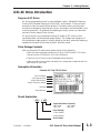
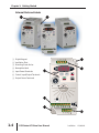
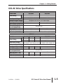
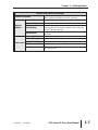
GETTING STARTED
CHAPTER
1
Contents of this Chapter...
Manual Overview . . . . . . . . . . . . . . . . . . . . . . . . . . . . . . . . . . . . .1–2
Overview of this Publication . . . . . . . . . . . . . . . . . . . . . . . . . . . . . . . . . .1–2
Who Should Read This Manual . . . . . . . . . . . . . . . . . . . . . . . . . . . . . . .1–2
Supplemental Publications . . . . . . . . . . . . . . . . . . . . . . . . . . . . . . . . . . .1–2
Technical Support . . . . . . . . . . . . . . . . . . . . . . . . . . . . . . . . . . . . . . . . .1–2
Special Symbols . . . . . . . . . . . . . . . . . . . . . . . . . . . . . . . . . . . . . . . . . . .1–2
GS1 AC Drive Introduction . . . . . . . . . . . . . . . . . . . . . . . . . . . . . .1–3
Purpose of AC Drives . . . . . . . . . . . . . . . . . . . . . . . . . . . . . . . . . . . . . . .1–3
Drive Package Contents . . . . . . . . . . . . . . . . . . . . . . . . . . . . . . . . . . . . .1–3
Nameplate Information . . . . . . . . . . . . . . . . . . . . . . . . . . . . . . . . . . . . .1–3
Model Explanation . . . . . . . . . . . . . . . . . . . . . . . . . . . . . . . . . . . . . . . . .1–3
External Parts and Labels . . . . . . . . . . . . . . . . . . . . . . . . . . . . . . . . . . . .1–4
GS1 AC Drive Specifications . . . . . . . . . . . . . . . . . . . . . . . . . . . . .1–5
Chapter 1: Getting Started
Manual Overview
Overview of this Publication
The GS1 AC Drive User Manual describes the installation, configuration, and
methods of operation of the GS1 Series AC Drive.
Who Should Read This Manual
This manual contains important information for those who will install, maintain,
and/or operate any of the GS1 Series AC Drives.
Supplemental Publications
The National Electrical Manufacturers Association (NEMA) publishes many
different documents that discuss standards for industrial control equipment.
Global Engineering Documents handles the sale of NEMA documents. For more
information, you can contact Global Engineering Documents at:
15 Inverness Way East
Englewood, CO 80112-5776
1-800-854-7179 (within the U.S.)
303-397-7956 (international)
www.global.ihs.com
NEMA documents that might assist with your AC drive systems are:
• Application Guide for AC Adjustable Speed Drive Systems
• Safety Standards for Construction and Guide for Selection, Installation, and
Operation of Adjustable Speed Drive Systems.
Technical Support
By Telephone: 770-844-4200
(Mon.-Fri., 9:00 a.m.-6:00 p.m. E.T.)
On the Web: www.automationdirect.com
Our technical support group is glad to work with you in answering your questions.
If you cannot find the solution to your particular application, or, if for any reason
you need additional technical assistance, please call technical support at
770-844-4200. We are available weekdays from 9:00 a.m. to 6:00 p.m. Eastern
Time.
We also encourage you to visit our web site where you can find technical and
non-technical information about our products and our company. Visit us at
www.automationdirect.com.
Special Symbols
When you see the “notepad” icon in the left-hand margin, the paragraph to its
immediate right will be a special note.
When you see the “exclamation mark” icon in the left-hand margin, the paragraph to
its immediate right will be a WARNING. This information could prevent injury, loss
of property, or even death (in extreme cases).
1–2
GS1 Series AC Drive User Manual
2nd Edition
07/06/2011
Chapter 1: Getting Started
GS1 AC Drive Introduction
Purpose of AC Drives
AC drives are generally known by many different names: Adjustable Frequency
Drives (AFD), Variable Frequency Drives (VFD), and Inverters. Drives are used
primarily to vary the speed of three phase AC induction motors, and they also
provide non-emergency start and stop control, acceleration and deceleration, and
overload protection. By gradually accelerating the motor, drives can reduce the
amount of motor startup inrush current.
AC drives function by converting incoming AC power to DC, which is then
synthesized back into three phase output power. The voltage and frequency of
this synthesized output power is directly varied by the drive, where the frequency
determines the speed of the three phase AC induction motor.
Drive Package Contents
After receiving the AC motor drive, please check for the following:
• Make sure that the package includes an AC drive, the GS1 Series AC Drive User
Manual, and the GS1 Series AC Drive Quick Reference.
• Inspect the unit to insure it was not damaged during shipment.
• Make sure that the part number indicated on the nameplate corresponds with the
part number of your order.
Nameplate Information
Example of 0.5 hp 115 VAC drive
AC Drive Model
Input Specification
Output Specification
Output Frequency Range
Barcode
Serial Number
Model Explanation
GS1 - 1 0P5
Applicable Motor Capacity
0P2: 1/4HP
1P0: 1HP
0P5: 1/2HP
2P0: 2HP
Input Voltage
1: 100–120VAC
2: 200–240VAC
Series Name
2nd Edition
07/06/2011
GS1 Series AC Drive User Manual
1–3
Chapter 1: Getting Started
External Parts and Labels
�
�
�
� Digital Keypad
� Ventilation Slots
� Mounting Screw Holes
� Nameplate Label
� Input Power Terminals
�
�
� Control Input/Output Terminals
� Output Power Terminals
�
�
�
1–4
GS1 Series AC Drive User Manual
2nd Edition
07/06/2011
Chapter 1: Getting Started
GS1 AC Drive Specifications
115V Class
Model Name
Motor Rating
HP
kW
Rated Input Voltage
Maximum Output Voltage
Rated Input Current (A)
Rated Output Current (A)
Short Circuit Withstand
(A, rms symmetrical)
Watt Loss 100% I (W)
Weight (lb)
Dimensions (HxWxD)
GS1-10P2
GS1-10P5
1/4 hp
1/2 hp
0.2 kW
0.4 kW
Single-phase: 100–120 VAC ±10%, 50/60 Hz, ±5%
Three-phase: 200–240 VAC ( x2 of input voltage)
6
9
1.6
2.5
5kA @ 120 VAC
19.2
19.2
2.16
2.24
132.0 mm [5.20 in] x 68.0 mm [2.68 in] x 128.1 mm [5.04 in]
230V Class
Model Name
Motor Rating
GS1-20P2 GS1-20P5 GS1-21P0
HP
kW
Rated Input Voltage
Maximum Output Voltage
Rated Input Current (A)
Rated Output Current (A)
Short Circuit Withstand
(A, rms symmetrical)
Watt Loss 100% I (W)
Weight (lb)
Dimensions (HxWxD)
2nd Edition
07/06/2011
GS1-22P0
1/4 hp
1/2 hp
1 hp
2 hp
0.2 kW
0.4 kW
0.7 kW
1.5 kW
Single/three-phase:
Three-phase:
200–240 VAC ±10%, 50/60 Hz ±5% 200–240VAC ±10%, 50/60Hz ±5%
Three-phase: 200–240VAC (proportional to input voltage)
4.9/1.9
6.5/2.7
9.7/5.1
9
1.6
2.5
4.2
7.0
5kA @ 240 VAC
18.4
26.8
44.6
73
2.06
2.2
2.26
2.2
132.0 mm [5.20 in] x 68.0 mm [2.68 in] x 128.1 mm [5.04 in]
GS1 Series AC Drive User Manual
1–5
Chapter 1: Getting Started
General Specifications
Control Characteristics
Control System
Rated Output Frequency
Output Frequency Resolution
Overload Capacity
Torque Characteristics
Sinusoidal Pulse Width Modulation, carrier frequency 3–10 kHz
1.0 to 400.0 Hz
0.1 Hz
150% of rated current for 1 minute
Includes auto-slip compensation and starting torque 150% @ 5.0 Hz
Operation frequency: 0 to 60 Hz, 0–30% rated voltage.
Start time 0.0–5.0 seconds. Stop time 0.0–25.0 seconds
DC Braking
Acceleration/Deceleration Time 0.1 to 600 seconds (can be set individually)
Voltage/Frequency Pattern
V/F pattern adjustable. Settings available for
Constant Torque - low and high starting torque,
Variable Torque - low and high starting torque,
and user configured
Stall Prevention Level
20 to 200% or rated current
Operation Specifications
Keypad
Frequency
External
Setting
Signal
Potentiometer - 3 to 5kΩ, 0.5W; 0 to 10 VDC (input impedance
10 kΩ); 0 to 20 mA / 4 to 20 mA (input impedance 250Ω);
Multi-function inputs 3 and 4 (3 steps, JOG, UP/DOWN command);
RS-485 communication setting
Keypad
Operation
External
Setting
Signal
Setting by <RUN>, <STOP> buttons
Inputs
DI1, DI2, DI3, DI4 can be combined to offer various modes of
operation, RS-485 communication port
Digital
4 user-programmable: FWD/STOP, REV/STOP, RUN/STOP,
REV/FWD, RUN momentary (N.O.), STOP momentary (N.C.),
External Fault (N.O./N.C.), External Reset, Multi-Speed Bit
(1and 2), Jog, External Base Block (N.O./N.C.), Second Accel/Decel
Time, Speed Hold, Increase Speed, Decrease Speed, Reset Speed to
Zero, Input Disable
Analog
1 user-configurable, 10 bit resolution
0 to 10 VAC, (input impedance 10 kΩ),
0 to 20 mA, (input impedance 250Ω)
4 to 20 mA, (input impedance 250Ω)
Input
Terminals
Output
Digital
Terminals
1 user programmable: AC drive Running, AC drive Fault,
At Speed, Zero Speed, Above Desired Frequency (P 3-16), Below
Desired Frequency (P 3-16), At Maximum Speed,
Over-torque Detected, Above Desired Current (P3-17),
Below Desired Current (P 3-17)
Operating Functions
Automatic voltage regulation, S-curve, Over-voltage stall prevention,
DC braking, Fault records, Adjustable carried frequency, Starting
frequency setting of DC braking, Over-current stall prevention,
Momentary power loss restart, Reverse inhibition, Frequency limits,
Parameter lock/reset
Outputs
1–6
Setting by <UP> or <DOWN> buttons or potentiometer
GS1 Series AC Drive User Manual
2nd Edition
07/06/2011
Chapter 1: Getting Started
General Specifications (continued)
Protective Functions
Operator Devices
Programming
Operator
Interface
5-key, 4-digit, 7-segment LED, 4 status LEDs, potentiometer
Parameter values for setup and review, fault codes
Status Display
Master Frequency, Output Frequency, Scaled Output Frequency,
Output Voltage, DC Bus Voltage, Output Direction, Trip Event
Monitor, Trip History Monitor
Key Functions
RUN/STOP, DISPLAY/RESET, PROGRAM/ENTER, <UP>,
<DOWN>
Enclosure Rating
Ambient Temperature
Environment Ambient Humidity
Vibration
Installation Location
2nd Edition
Overcurrent, Overvoltage, Undervoltage, Electronic thermal
motor overload, Overheating, Overload, Self testing
07/06/2011
Protected chassis, IP20
-10° to 40°C (14°F to 104°F) w/o derating
0 to 90% RH (non-condensing)
9.8 m/s2(1G), less than 10 Hz; 5.88 m/s2 (0.6G) 20 to 50 Hz
Altitude 1000m or lower above sea level, keep from corrosive
gas, liquid and dust
GS1 Series AC Drive User Manual
1–7
Chapter 1: Getting Started
1–8
GS1 Series AC Drive User Manual
2nd Edition
07/06/2011