1
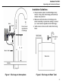
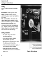
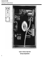
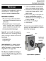
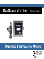
GASGUARD VENT LINE3
Ammonia Sensor
OPERATING & INSTALLATION MANUAL
GasGuard VL-NH3
Operating and Installation Manual
2
GasGuard VL-NH3
Operating and Instruction Manual
Table of Contents
General description ………………………………. 4
Installation………………………………….………. 4
Locating the sensor …………………………. 4
Installation guidelines………………………… 5
Wiring………………………………………….. 6
Operation ………………………………………….. 7
Start-up ……………………………………….. 7
Calibration ……………………………….….… 7
Maintenance…………………………….………… 9
Troubleshooting………………………………….. 10
Specifications…………………………………….. 10
Warranty………………………………………….. 11
Calibration Technologies
866-394-5861
3
GasGuard VL-NH3
Operating and Installation Manual
General Description
Installation
The GasGuard VL-NH3 sensor is a +24 VDC, threewire, 4/20 mA sensor for ammonia. It provides an
industry standard linear 4/20 mA output signal
compatible with most gas detection systems and PLCs.
Locating the sensor
The GasGuard VL-NH3 provides real-time continuous
monitoring of ammonia vapors in refrigeration system
vent lines. Utilizing a rugged and long-life solid-state
sensor, the GasGuard VL-NH3 sensor can withstand
continuous exposures to high concentrations of
ammonia vapors, without shortening the life of the
sensor.
Note: The ½” nipple of the supplied mounting kit should
be welded to the relief header to allow airflow to the
sensor.
The sensor is housed in the mounting kit, which is
connected to the backside of the sensor enclosure. The
union of the mounting kit “breaks apart” allowing for
simple sensor field replacement.
Discharging to Atmosphere
The GasGuard VL-NH3 sensor assembly should be
installed outdoors three to five feet above the roofline,
where the relief header discharges to the atmosphere
(see Figure 1).
The transmitter circuit board is sealed in potting
compound, protecting sensitive electronic components
and copper tracing from corrosion. The stainless steel
enclosure protects the transmitter from chemical and
UV damage.
Recommended alarm setpoints for ammonia system
vent lines are typically 0.5 – 1.0% NH3 (12 – 20 mA).
Setpoints lower than this may result in occasional false
alarms due to inclement weather or interference gases
(i.e. truck exhaust, condenser steam, etc.)
4
Warning: Outdoor installation only. Never install
the sensor indoors (i.e., Engine Room)
Note: Removing the ½” plug from the mounting kit
usually allows more fresh air to the sensor and prevents
signal rise over time.
Discharging to Water Tank
The GasGuard VL-NH3 sensor assembly should be
installed on the atmospheric vent on top of the water
tank (see Figure 2). This type of installation will not
catch the weeping relief valves, but will detect ammonia
vapors from the water during a release event.
GasGuard VL-NH3
Operating and Instruction Manual
Installation Guidelines:
Union
Nipple
Relief header
• Always assume system could discharge at any
Mount sensor
opposite side
of discharge
moment. Stay clear of discharge path and have
escape route planned.
• Make sure ammonia does not discharge onto
sensor assembly or personnel working on sensor
(i.e. mount sensor opposite side of discharge).
• Install sensor enclosure with conduit hole facing
down.
Relief header
Atmospheric
vent
½” plug
3’ – 5’
Sensor cable
Water tank
Roofline
Figure 1: Discharge to Atmosphere
Figure 2: Discharge to Water Tank
5
GasGuard VL-NH3
Operating and Installation Manual
Wiring
Electrical wiring must comply with all applicable
codes.
Electrical Power: 24 VDC regulated, 250 mA.
Output: Linear 4/20 mA output. Monitoring
equipment may have a maximum input impedance
of 700 ohms.
Cable Recommendation: 20/3 shielded cable
(General Cable C2525A or equivalent). Length of
cable to sensor should be no greater than 1,500 feet.
Monitoring: Monitoring equipment must be
configured to indicate a fault if the signal is below
1 mA. All signals over 20 mA must be considered
high gas concentrations. Alarm setpoints should
not be lower than 50% of full-scale range.
Sensor
Connector
Wiring Guidelines:
• Use only the existing conduit hole for
connections to the sensor.
• Always use three conductor, insulated,
stranded, shielded copper cable.
• Do not pull sensor wiring with AC power cables.
This can cause electrical interference.
• If cable runs cannot be made without a splice, all
splice connections should be soldered.
• Ground the shield at the main control panel.
Connect the shield wire in the sensor terminal block
labeled SHLD.
6
Figure 3: Wiring diagram
GasGuard VL-NH3
Operating and Instruction Manual
Operation
Start-up
Before applying power, make a final check of all wiring
for continuity, shorts, grounds, etc. It is usually best to
disconnect external alarms and other equipment from
the sensor until the initial start-up procedures are
completed.
After power-up, allow at least 12 hours for the system to
stabilize before testing the sensors. Because sensors
are normally located at a distance from the main unit,
the test time required and accuracy of the response
checks will be improved if two people perform the startup procedures and use radio contact.
Response Test:
1. One person removes the ½” plug in the tee and
injects a small amount of propane/butane from an
unlit plumber’s torch.
2. The second person stays at the control panel to
determine that each sensor, when exposed to the
gas, is connected to the proper input and responds,
causing appropriate alarm functions.
Calibration
The GasGuard VL-NH3 Sensor comes factory
calibrated and should not require any adjustments after
installation. If any adjustments are required, there are
two pots on the preamp that are used for calibration.
Note: Never measure sensor output in mA. Always
use mVDC or VDC voltmeter settings.
Zero Calibration: After the unit is installed and has
been powered up for a minimum of 24 hours, the unit
can be zero calibrated by the following:
• Be sure the unit is in clean air with no noticeable
ammonia vapors.
• Adjust the zero pot until the sensor outputs 40 mV
from Test [-] to Test [+] (see Figure 4).
Span Calibration: It is recommended that the
GasGuard VL-NH3 sensor be response tested only,
every six months. Refer to the Response Test
procedure on this page.
If span calibration is required, the following procedure
will span the unit:
• Unscrew the union nut of mounting kit, making sure
to support weight of sensor assembly. This will
expose the sensor and allow for a more accurate
span calibration (see Figure 5).
• Apply 1% NH3 span gas at 0.8 L/min.
• Once the output signal has peaked (or one minute
maximum) adjust the span pot until the sensor
outputs 200 mV from Test [-] to Test [+]
(see Figure 4).
7
GasGuard VL-NH3
Operating and Installation Manual
Figure 4: Sensor output and
zero/span adjustments
8
GasGuard VL-NH3
Operating and Instruction Manual
Maintenance
The GasGuard VL-NH3 was designed for long life and
minimal maintenance. Calibration Technologies
recommends the following maintenance schedule
Maintenance Guidelines:
1.
2.
3.
4.
• The sensor is shipped with a factory calibration.
Sensor should be response tested 6 months from
purchase date.
• Response-test the sensor at least once every 6
months. The response test can be performed with
propane or butane from an unlit plumber’s torch.
• All tests and calibrations must be logged.
Sensor Life: Typical sensor life of the GasGuard VLNH3 sensor is five to seven years. Although extremely
reliable, a few things can cause the sensor to become
faulty including:
• a long period of time
• exposure to liquid
5.
6.
Loosen the screw terminals of sensor connector
(orange and red wires) and disconnect the wires.
Unscrew the union nut of mounting kit, making sure
to support weight of sensor assembly. This will
expose the sensor.
Remove sensor by pulling it out through the union.
Install new sensor and tighten sensor screw
terminals. Make sure the red and orange wires are
in their correct terminals.
Re-assemble sensor/mounting kit.
Discard old sensor.
The sensor can be response-tested immediately after
replacement. Zero/span calibration may be performed
after a 24 hour warm-up period.
Union nut
Sensor
Mounting kit with
union, tee, nipple
and test plug
Sensor Replacement: When the sensor becomes
faulty, a replacement sensor can be obtained from
Calibration Technologies. To replace the sensor, refer
to Figure 5 and the following procedure.
Note: Always assume system could discharge at
any moment. Stay clear of discharge path and have
escape route planned.
Figure 5: Sensor replacement
9
GasGuard VL-NH3
Operating and Installation Manual
Troubleshooting
Specifications
Sensor Fault: (low signal reading)
Indications: (any or all)
• Red LED on transmitter lit.
• Voltage signal at testpoints is 5 mVdc (.5 mA output).
• PLC displays negative value (i.e., -2150 ppm).
• Controller indicates sensor fault or sensor failure
Possible Cause / Solution:
• Sensor exposed to liquid. Replace sensor element
(see page 9 for more info).
• Loose connection. Check and tighten sensor wires.
Detection Principle: Solid-state
Detection Method: Diffusion
Gas: Ammonia (NH3)
Range: 0/1% (10,000 ppm)
Output Signal:
Linear 4/20 mA (max input impedance: 700 Ohms)
Power Supply: +24 VDC, 250 mA
Response Time:
T90 = less than 30 seconds
Accuracy:
+/- 5% of value,
Zero Drift: Less than 1% per month, non-cumulative
Span Drift: Less than 1% of full-scale per month, noncumulative
Linearity: +/- 5% of full-scale
Repeatability: +/- 5% of full-scale
Wiring Connections:
3-conductor, shielded, stranded, 20 AWG cable
(General Cable C2525A or equivalent) up to 1500 ft.
Enclosure: 18 ga stainless steel housing. Captive
screw in hinged lid. For non-classified areas.
Mounting Kit: Schedule 80 NPT pipe fittings
Temperature Range:
-46°F to +140°F (-46°C to +60°C)
Dimensions: 4.8” high x 4.72” wide x 3.35” deep
Weight: 4 lbs (includes mounting kit)
Constant or Intermittent high signal or alarms:
Indications:
• Erratic or constant high concentration reading at
controller or PLC.
Possible Cause / Solution:
• Weeping relief valve. Check valve by drawing a
sample from the header with an accurate portable
ammonia detector. Be sure to sample 1’ to 3’ from
inside the header to ensure a good reading.
or loosen union nut and remove sensor assembly
from header. If signal returns to normal in fresh air,
investigate relief valve(s) and replace if necessary.
• Condenser steam. Re-install the ½“ plug or install
pipe in its place, lowered below the condenser steam
level to allow a fresh-air vent to the sensor.
• Sensor aged beyond its useful life (hypersensitive).
Replace sensor element (see page 9 for more info).
10
Limited Warranty & Limitation of Liability
Calibration Technologies, Inc. (CTI) warrants this product to be free from defects in material and workmanship under
normal use and service for a period of one year (including sensor), beginning on the date of shipment to the buyer.
This warranty extends only to the sale of new and unused products to the original buyer. CTI’s warranty obligation is
limited, at CTI’s option, to refund of the purchase price, repair, or replacement of a defective product that is returned to
a CTI authorized service center within the warranty period. In no event shall CTI’s liability hereunder exceed the
purchase price actually paid by the buyer for the Product.
This warranty does not include:
a) gas sensors that have been wetted by liquid ammonia, oil or water
b) routine replacement of parts due to the normal wear and tear of the product arising from use;
c) any product which in CTI’s opinion, has been misused, altered, neglected or damaged by accident or abnormal
conditions of operation, handling or use;
d) any damage or defects attributable to repair of the product by any person other than an authorized dealer or
contractor, or the installation of unapproved parts on the product
The obligations set forth in this warranty are conditional on:
a) proper storage, installation, calibration, use, maintenance and compliance with the product manual instructions
and any other applicable recommendations of CTI;
b) the buyer promptly notifying CTI of any defect and, if required, promptly making the product available for
correction. No goods shall be returned to CTI until receipt by the buyer of shipping instructions from CTI; and
c) the right of CTI to require that the buyer provide proof of purchase such as the original invoice, bill of sale or
packing slip to establish that the product is within the warranty period.
THE BUYER AGREES THAT THIS WARRANTY IS THE BUYER’S SOLE AND EXCLUSIVE REMEDY AND IS IN
LIEU OF ALL OTHER WARRANTIES, EXPRESS OR IMPLIED, INCLUDING BUT NOT LIMITED TO ANY IMPLIED
WARRANTY OF MERCHANTABILITY OR FITNESS FOR A PARTICULAR PURPOSE. CTI SHALL NOT BE LIABLE
FOR ANY SPECIAL, INDIRECT, INCIDENTAL OR CONSEQUENTIAL DAMAGES OR LOSSES, INCLUDING LOSS
OF DATA, WHETHER ARISING FROM BREACH OF WARRANTY OR BASED ON CONTRACT, TORT OR
RELIANCE OR ANY OTHER THEORY.
11
06/2013