1
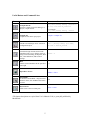
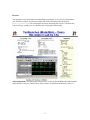
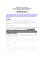
Massachusetts Institute of Technology
Department of Electrical Engineering and Computer Science
6.111 – Introductory Digital Systems Laboratory
ModelSim/Verilog Tutorial
Authors: David Milliner, Frank Honoré, Spring, 2004
Jenny Lee, Spring, 2005
* There have been some important changes to this document, which are indicated by underlining. If you have
already read this document, please read at least the underlined parts. The newly added/modified sections are
What are Library and Project, Creating Files in ModelSim, and Wave Window, and Useful Buttons and
Command Lines.
Introduction
This tutorial is designed to familiarize you with Verilog coding/syntax and simulation in the
ModelSim environment. Verilog HDL is a hardware description language used to design digital
systems. Along with VHDL, Verilog is the primary industry tool for programming digital systems.
ModelSim is the industry standard simulation tool for verifying digital designs.
Directory Structure
When you log into the lab computers you will have access to your own drive (U:/) and a directory
in the local drive (E:/) where you can store your files for this class. For ModelSim to operate
correctly, you must store all your source files (*.v) in E:/Documents and Settings/[Athena
Username]/Desktop or equivalently on the Desktop of your local machine. This directory is linked
directly to U:/Desktop, but please make sure you use source files stored in E:/ directory rather than
U:/Desktop when using ModelSim.
Although this directory is accessible from any computers in the lab area, you will probably want to
back these files up on your Athena account from time to time. You can transfer files back and forth
from your Athena account using WinSCP.
On the Desktop of your local computer, create a tutorial folder with the subfolders src and sims.
The src folder will contain the source codes for this tutorial and the sims directory is where you will
be compiling your code. On the lab PCs you will see a shared drive (S:/) from which you should be
able to access the files necessary for this tutorial. Copy the files from the S:/6.111/tutorial2/ folder
to your src folder on your Desktop. The files to copy are counter.v, top.v, tb_tutorial.v,
full_adder.v, full_adder_4bit.v, and test_adder.v.
Verilog Source Code and Testbench
The file counter.v is a simple two-bit Verilog counter designed to divide the input clock by four.
This counter is designed to reset back to zero on the positive assertion of the reset signal. Your
counter is instantiated in the top level file top.v. The file tb_tutorial.v is used to simulate the
counter module in counter.v. We recommend you spend a few minutes familiarizing yourself
with this code and the Verilog syntax.
1
Opening ModelSim
You can access ModelSim either through the PCs in the lab or an Athena Sun Workstation. On the
Lab PC under Windows XP, launch ModelSim from the Desktop icon (or Start > All Programs >
ModelSim SE > ModelSim).
If it’s your first time opening ModelSim or if you encounter problems with licenses, you can run the
license wizard: Start > All Programs > ModelSim SE > Licensing Wizard. The license file should
be set to ‘[email protected]’.
On Athena Sun workstation, first run 'setup 6.111' to configure your environment correctly.
Then run 'vsim &' to start the application.
Online help and tutorials for ModelSim are available from the Help pull-down menu. Help > SE
PDF Documentation > Tutorial will bring up the guide for a recommended tutorial. The PDF for the
user's manual is also available on the course website: Software Tools > Verilog Simulation. (must
have MIT certificates).
What are Library and Project?
Before jumping into using ModelSim, there are two important components you should get familiar
with: Library and Project. Library provides an environment for you to compile and simulate your
design, while Project provides you a place to contain all relevant files and settings for independent
design including its working library.
Library:
A directory that contains compiled design units, such as modules. There are two types of
libraries: Resource Library and Working Library:
Resource Library:
contains static contents, such as the compiled version of standard modules. Resource
libraries, such as ieee, can be found in the ‘library’ pane on the left-hand side of
ModelSim.
Working Library:
contains the compiled version of your design. The contents of a working library change
every time you compile your design. The default working library in ModelSim is named
work and is predefined in the ModelSim compiler. The working library when created or
linked to your source code can be accessed through the ‘library’ pane on the left-hand side
of ModelSim.
Project:
A collection of various files for designs under test, such as Verilog source files, local working
libraries, references to resource libraries, and simulation configuration (*.mpf files).
2
Creating files in ModelSim
There are two ways to start creating your designs in ModelSim: 1.Creating a project or 2.Opening
or creating a Verilog file without a project.
1. Creating a project
Create a new project: File > New > Project
Specify your project name and specify the Project Location as a directory under
E:\Documents and Settings\[username]\Desktop. Leave the Default Library Name
to work. Now, you have created a project .mpf file and a working library, which can store
useful information, such as your simulation configuration, for future use.
Now, add items to your project by either creating a new Verilog source file or adding an
existing file.
2. Creating without a project:
Create a new file: File > New > Source > Verilog or open an existing Verilog file: File > Open
> File. To compile the source files in the ModelSim environment, you must create a working
directory or map an existing working directory: File > New > Library or File > Import >
Library or type ‘vlib work’ in the command line window.
As a good design practice, we recommend you to follow the first option: creating a new project.
For Verilog files required for labs and psets, create a new project such as ‘lab01’ or ‘pset03’ under
the default work library as its working library, because you do not explicitly need to specify the
work library when compiling. For the final project, which contains many layers of hierarchy, create
a new project under a new working library, such as ‘final_proj’.
For this tutorial, we are using the second option: opening existing files and creating a new working
library called sims. If you are not already located in your sims directory, then move into this
directory using the ModelSim command line. On the left-hand side of the ModelSim window, you
should see a number of resource libraries (vital2000, ieee, etc...): Right-click in this window and
select to create a new library, called ‘sims’, or type ‘vlib sims’ in the command line.
Compiling in ModelSim
Compile source files: Compile > Compile. You will see that the default library is the work library.
Choose to compile your files in the newly created sims library rather than the work library.
To compile your files, browse to your src directory and select the files counter.v, top.v and
tb_tutorial.v. Double-click the selected files to compile. We will use the other files later in
this tutorial. If there is an error in your Verilog code it will be reported at this time with an error
message. Your downloaded tutorial files should not contain any errors.
3
You can recompile your files by looking at the ‘library’ pane. On the left-hand side of ModelSim
window, choose the ‘library’ tab and click on the square containing plus sign next to sims working
library. You should see the three files you compiled earlier under sims library. Highlight the files
you want to recompile, and when you right-click on those files, you can delete, recompile or
simulate the highlighted files.
Simulation
You are now ready to simulate the counter module using the testbench tb_tutorial.v in your
sims directory. To simulate, you can either use the graphic interface (see Useful Buttons and
Command Line section) or use the commands described below:
To simulate your testbench:
> vsim sims.tb_tutorial
To run the testbench:
> run 100us
To restart your simulation:
> restart –f
Viewing Simulations – The Wave Window
To graphically view your testbench pull down the View menu: View > Debug Windows > Wave.
From the left-hand side of the ModelSim window, you should see blue dots representing the
modules in your design. This should have occurred when you compiled your testbench. Drag the
blue dot representing the modules in your design into the Wave window.
In the Wave window, if you do not want to use testbench, you can also specify the behaviors of
your input waveforms, just like in Max+ Plus II. Right-click on the input signal, a, b or cin and
select Create/Modify Waveform. You can set the input signals to a clock, constant, random,
repeater or counter. Once you set the input signals, you can also manually draw the waveform by
highlighting the parts of your wave, right-click, and select Edit Wave > Invert or Mirror or Value.
Restart your simulation (type restart –f) and run for 100us. You should see the clock signal,
reset signal, clock divided by four signal, and two-bit counter value. Zoom out to see the entire
Wave window. You can select to have your data represented in a number of different ways although
most of you will probably choose to use binary or decimal representation.
By default, when you close the Wave window, all the information is forgotten. Thus, if you want to
save your waveforms, you must save a Wave window format file (*.do) under your project: File >
Save > Format.
4
Useful Buttons and Command Lines
Buttons
Description*
Command Line
To compile:
Compile this file
open the Compile Source File dialog; in a
project, compile the file
vlog -work [working library] [filename.v]
ex) vlog –work work tb_tutorial.v
To recompile:
vlog –work [working library] –refresh
Compile All
compile all files in the open project
Compile > Compile All
Simulate
load the selected design unit or simulation
configuration object
vsim -c [working library].[file name]
Restart
reload the design elements and reset the
simulation time to zero, with the option of
using current formatting, breakpoints, WLF
file, virtual definitions, and assertion
settings
restart -f
Run
run the current simulation for the specified
run length
run
Open Wave Viewer
Ex) vsim –c work.tb_tutorial
Window > Wave
Zoom Mode
set mouse to Zoom Mode – drag left mouse
button to zoom, click middle mouse button
to select
N/A
Insert Cursor
add a cursor to the waveform pane
Insert > Cursor
*The button descriptions are copied from User’s Manual v5.8b (se_man.pdf) published by
ModelSim®.
5
Exercise
You should now feel comfortable in the ModelSim environment. As an exercise to demonstrate
your familiarity with the environment compile and run the full-adder testbench found at
(S:/6.111/tutorial2). The viewgraph from lecture describing this exercise is shown below.
You can also try creating your own modules and verifying their functionality.
Acknowledgements: This tutorial and counter code is written by David Milliner and adder module
and testbench is written by Frank Honoré. Some sections are added and modified by Jenny Lee.
6