1
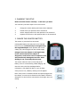
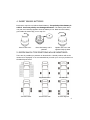
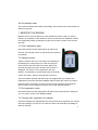
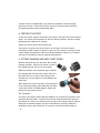
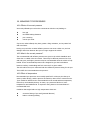
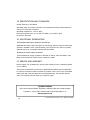
Tyre Pressure Monitoring System
TA22X
User manual
TA22X20130518
CONTENTS
1. IMPORTANT SAFETY NOTES .............................................................................. 3
1.1 System safety ............................................................................................ 3
1.2 Batteries and small parts ............................................................................ 3
1.3 Use of tyre sealant ..................................................................................... 3
1.4 Before installation ..................................................................................... 3
2. PLANNING THE SETUP ...................................................................................... 4
3. CHARGE THE MONITOR BATTERY ...................................................................... 4
4. INSERT SENSOR BATTERIES ............................................................................. 5
5. DECIDE WHICH TYRE POSITIONS WILL BE MONITORED .................................... 5
6. SET TARGET PRESSURES AND UNITS ................................................................ 6
6.1 Enter settings mode ................................................................................... 6
6.2 Change units.............................................................................................. 6
6.3 Set tyre pressures ...................................................................................... 6
6.4 Exit settings mode...................................................................................... 7
7. Register sensors ................................................................................................ 7
7.1 Enter registration mode .............................................................................. 7
7.2 Register sensors ......................................................................................... 7
7.3 Exit registration mode ................................................................................ 7
7.4 Changes after registration is complete ......................................................... 7
8. TESTING THE SETUP......................................................................................... 8
9. FITTING SENSORS AND ANTI-THEFT RINGS ...................................................... 8
9.1 Corrosion ................................................................................................... 8
9.2 Anti-corrosion precautions .......................................................................... 9
10 WHEEL BALANCING .......................................................................................... 9
11. CONNECTING AND DISCONNECTING A TRAILER .............................................. 9
12 WARNINGS AND ALARMS ............................................................................... 10
12.1 Blow-out ................................................................................................ 10
12.2 Rapid air loss ......................................................................................... 10
12.3 Low tyre pressure................................................................................... 10
12.4 High tyre pressure .................................................................................. 11
12.5 High tyre temperature ............................................................................ 11
13. CHECKING TYRE PRESSURES ......................................................................... 11
14. TURNING ON AND OFF .................................................................................. 12
15. RESETTING THEMONITOR ............................................................................. 12
16. SIGNAL BOOSTER ......................................................................................... 13
17. TROUBLESHOOTING ..................................................................................... 13
17.1 Blank display .......................................................................................... 13
17.2 Difficulty in registering ............................................................................ 13
17.3 No signal noS ......................................................................................... 14
17.4 Incorrect pressure alerts ......................................................................... 14
17.5 False leak alert on stopping .................................................................... 14
17.6 Displayed pressure disagrees with a pressure gauge ................................ 14
18. MANAGING TYRE PRESSURES ....................................................................... 15
18.1 Effects of incorrect tyre pressure ............................................................. 15
18.2 What is the correct pressure? .................................................................. 15
18.3 Effect of temperature ............................................................................. 15
19. SPECIFICATION AND STANDARDS ................................................................. 16
20. ADDITIONAL INFORMATION .......................................................................... 16
21. SERVICE AND WARRANTY ............................................................................. 16
2
1. IMPORTANT SAFETY NOTES
Please read the following important safety information before installing
the system.
1.1 System safety
TyrePal TA22X monitors up to 22 tyres, and provides an immediate warning if the
pressure or temperature of any tyre deviates from pre-set levels. It is intended to
help you maintain your tyre pressures at the optimum levels for safety, fuel
economy, tyre life and environmental impact.
It is your responsibility to ensure that it is suitable for your particular vehicle and
that it is working correctly and properly maintained. Check the sensors and valve
stems regularly, as some road salts can cause corrosion.
The system does not replace the need to carry out regular checks on the
condition and wear of your tyres.
1.2 Batteries and small parts
Keep the small parts and especially the batteries out of the reach of children. If a
battery is swallowed, consult a doctor. Do not hold a battery with metallic tweezers.
It may cause a short circuit. Do not recharge, disassemble or dispose of batteries in
a fire. Batteries can explode if mistreated.
1.3 Use of tyre sealant
Sensors should not be fitted to tyres that have been treated with internal tyre
sealant. The sealant may damage the sensor or impair its action.
1.4 Before installation
Before installing the system, ensure that it is suitable for your vehicle.
•
Check that the operating pressure of your tyres is within the range of the
system. i.e. 0 - 10 bar (0-145psi).
•
Check that sensor valve caps will remain within the outside profile of the
tyres when fitted.
•
•
•
Check that tyre valve stems are in good condition before fitting the sensors.
Do not use with aluminium valve stems.
Select a location for the monitor unit so that it is visible to the driver
without obstructing visibility.
3
2. PLANNING THE SETUP
Please read this section carefully – it will save you time!
You must carry out these steps in the correct order.
1.
Charge the monitor battery and insert sensor batteries
2.
Decide which tyre positions will be monitored
3.
Set the target pressures for each position to be monitored
4.
Register the sensors to each position that is to be monitored
3. CHARGE THE MONITOR BATTERY
The monitor is powered from an internal
rechargeable battery that may need to be charged
before first use. It should only be charged using
the supplied adapter which provides the correct
voltage (5V) when plugged into the vehicle supply.
Using an incorrect adapter or wiring directly
to the vehicle without the adapter is
dangerous, could cause a fire or explosion and
will permanently damage the monitor. Such
damage is not covered by the warranty.
The monitor takes six hours to fully charge the
battery, but it is not harmed by partial charging and
does not have to be fully discharged before
recharging. A full charge will last for up to 30 days.
If the power is low, a battery warning icon will appear.
Note: If the power is switched off with the system plugged into
the charger, current may be drawn from the battery instead of
charging it, so don’t leave it connected to the charger when not
driving.
4
4. INSERT SENSOR BATTERIES
Each sensor requires one lithium CR1632 battery. The polarity of the battery is
critical. Incorrect polarity can damage the sensor. The battery lasts about
one year and a warning appears when the battery is low. Make sure the battery
goes inside the metal cage, not on top of it.
Unscrew the cover
Insert the battery with +
upwards
Replace the cover and
tighten firmly by hand
5. DECIDE WHICH TYRE POSITIONS WILL BE MONITORED
There are 22 possible tyre positions as shown below. Unused positions will not be
monitored or displayed, so we recommend that you mark your own tyre positions on
the blank layout below.
Your positions
Single axle trailer
Car and trailer
Twin axle trailer
6-wheel twin rear
6-wheel tag axle
5
6. SET TARGET PRESSURES AND UNITS
The target pressure is the required normal cold operating pressure for each tyre as
recommended by the manufacturer. It is usually printed in the vehicle manual and
on a label in the driver’s door frame. It is not the same as the maximum pressure
embossed on the tyre wall.
The system automatically sets a series of alert levels commencing at 15% below the
target pressure, so if a target pressure is 100psi, you will be alerted when the
pressure of that tyre is down to 85psi. Note that this setting only affects the high
and low pressure alerts. A blow-out or rapid air loss will always trigger an alert.
6.1 Enter settings mode
Press and hold the centre button for about five seconds. The
front left tyre position icon flashes and the display shows the
default target pressure and the default units.
6.2 Change units
To change units, press the centre button 22 times to scroll
through all the tyre positions until the pressure icon in the
top left of the screen flashes. Press left or right buttons to
select the units you require.
Press the centre button to store the selection and move on to
temperature.
Press left or right to select the required temperature units and then press the centre
button to store the selection and move back to the first tyre position.
6.3 Set tyre pressures
Press left or right buttons to adjust the setting for the current (flashing) tyre
position. A single press changes by one step, holding it down gives a rapid change.
Press the centre button to store the setting and move on to the next position.
You must set the pressures for all the tyre positions you will be monitoring, but other
positions can be left at the factory default.
6
6.4 Exit settings mode
You must exit settings mode before proceeding. Press and hold the centre button for
about five seconds.
7. REGISTER THE SENSORS
Register sensors to the positions you have decided in section 5 that you want to
monitor. On completion, other positions will not be monitored or displayed. Sensors
are registered by simply screwing them onto the tyre valve in place of the normal
dust cap.
7.1 Enter registration mode
Press and hold the left and right buttons for about five
seconds. The red light comes on and the first tyre position
icon flashes.
7.2 Register sensors
Take the monitor with you to the wheel corresponding to
the flashing icon. Remove the tyre valve dust cap and
screw a sensor onto the valve in its place. After a few
seconds, the light turns green and the tyre pressure is
displayed. The sensor is now registered to this tyre
position. If registration is not achieved within 30 seconds,
remove the sensor, wait ten seconds and re-mount it.
The pack includes optional anti-theft rings. We suggest that you complete the
registration process and test the installation before locking the sensors in position.
Press the right or left button to move onto the next tyre position and repeat the
process until you have registered sensors to all of the required positions.
7.3 Exit registration mode
Press and hold the left and right buttons for about five seconds until the light goes
out. The screen reverts to the Standby display.
7.4 Changes after registration is complete
If pressure settings are changed after the sensors have been registered, the monitor
stores the settings, but they do not come into effect until it has been operating for
about 20 minutes.
7
If further sensors are added later, they must be registered to allow the target
pressures to be set. In this case it may be quicker to reset the entire system by
de-registering all the sensors and starting again.
8. TESTING THE SETUP
To test the system, position the monitor in the driver’s cab and unscrew the furthest
sensor. The system should produce an alert for that tyre position, with the red light
flashing and the ‘leaking’ icon showing.
Tighten the sensor and the alert should stop.
If the alert is not given, the sensor may be out of range. The sensors have a
transmission range of about 20 metres in open air, but in practice, screening by the
vehicle chassis and bodywork reduce the working distance to about 8 to 10 metres.
This can be increased by using the optional signal booster.
9. FITTING SENSORS AND ANTI-THEFT RINGS
Slide the anti-theft ring onto the valve with the bars
pointing outwards. Screw on the sensor in place of
the original dust cap, but do not over-tighten.
Adjust the position of the anti-theft ring so that the
bars engage with the slots in the sensor and lock it
into place with one or more of the locking screws
provided. Do not over-tighten or it may damage the
valve stem.
When all the tyre sensors are fitted, check that there
are no leaks by brushing a little detergent and water
on the valve stems. If bubbles appear, slacken the
locking key and refit the sensor.
9.1 Corrosion
Corrosion occurs mostly where different metals are in contact in the presence of an
electrolyte like salty water. TyrePal sensors have a brass thread and this presents
little danger of corrosion on normal brass tyre valves. The locking rings are made of
aluminium to minimise weight, so these are anodised for protection. While the
anodising is intact, there is little risk of corrosion, but if the anodized surface is
8
damaged, contact between the aluminium and the brass of the sensor or the tyre
valve will create a corrosion risk, especially during the winter when roads are salted.
9.2 Anti-corrosion precautions
1.
Put a small amount of WD40 or silicone grease on the locking ring and on
the threads of the valve stem. This film separates the different metals.
2.
Remove the sensors once a month during winter to prevent bonding.
3.
Remove the sensors if the vehicle is to be unused for several months.
4.
Do not use the locking rings if the vehicle is being used in extremely salty
conditions, such as a boat trailer where the wheels may be immersed in the
sea.
10. WHEEL BALANCING
The weight of the sensors is within the tolerance generally achieved for wheel
balancing, so there is usually no need for the wheels to be rebalanced after installing
the system. Some vehicles are more sensitive to wheel balance than others, so if
vibration is felt when driving at speed after fitting the system, the wheels must be
rebalanced.
11. CONNECTING AND DISCONNECTING A TRAILER
If you have sensors on both a towing vehicle and a trailer such as a caravan or a
towed car, when you no longer have the trailer attached, the system will recognise
this and will show noS (no signal) on the display. It can take some time before this
appears and during this period the pressures shown for the trailer are those which
were detected before the towing vehicle went out of range of the trailer. When the
system does finally show noS, there will be a single beep and the low sensor battery
icon may be shown.
When the towing vehicle returns within range of the trailer, no action is necessary,
and it will take about 20 minutes for the monitor to display the correct pressures of
the trailer. However, if you begin to tow during this perios, and a problem arises,
then the system will detect and warn you within six seconds as normal.
If the monitor is showing noS because the monitor is out of range of the trailer, the
sensor low battery warning can be ignored.
9
12. WARNINGS AND ALARMS
The system checks the tyre pressures and temperatures every six seconds and an
alert is given in the event of an abnormality, whether the vehicle is moving or
stationary. The level of alert depends on the severity of the abnormality. In each
case, the appropriate tyre icon flashes.
12.1 Blow-out
A tyre loses more than 3 psi in less than 2 minutes:
Constant beep-beep
White LCD screen flashes
Red LED flashes
Tyre position icon flashes
Blow Out icon appears in lower left corner
Tyre pressure flashes
12.2 Rapid air loss
A tyre loses 3 or more psi in 2 to 10 minutes:
Intermittent beep-beep
Red LED flashes
Tyre position icon flashes
Leaking icon appears in lower left corner
Tyre pressure flashes
12.3 Low tyre pressure
Blowout display
Rapid air loss
Tyre pressure is 15% to 25% below the target:
Intermittent beep every 15 seconds for five minutes
Red LED flashes
Tyre position icon flashes and pressure is displayed
Pressure icon shows 75% full
15 to 25%
To turn off the alert, press the right or left button. It will reactivate in
one hour if it is not corrected
25 to 50%
If tyre pressure is 25% to 50% below the target, the indication is similar,
except that the pressure icon will show 50% full. If more than 50%
below target, it will show empty.
10
below 50%
12.4 High tyre pressure
Tyre pressure rises 20% above the target level:
Intermittent beep-beep
Red LED flashes
Tyre position icon flashes
High pressure icon appears
Tyre pressure flashes
High pressure
Icon
12.5 High tyre temperature
Tyre temperature exceeds 75˚C:
Intermittent beep
Tyre position icon flashes and temperature is displayed
Temperature icon appears
To turn off the alert, press the right or left button.
If tyre temperature exceeds 85˚C, the indication is similar except
that beep-beep is continuous.
High temp
Icon
13. CHECKING TYRE PRESSURES
The TyrePal TA22X constantly monitors all tyre positions that have been
programmed. If you wish to check each tyre pressure and temperature, press either
the right or left button from "Stand By" mode. The tyre position will be displayed
along with its pressure. Press again and that tyre's temperature appears. Press again
to move on to the next tyre position that has been programmed.
Note that the pressure and temperature data displayed are not instantaneous, but
are values stored in the monitor. The system checks pressures and temperatures
every six seconds and gives an immediate warning when required, but to save
battery power, it only updates the full data every few minutes. To force an update,
unscrew the sensor to give a leaking alert and tighten it again to stop the alert and
transmit new data.
If a tyre position has been programmed but a transmitter is missing, out of range or
malfunctioning, the display will show "noS" (no signal).
11
14. TURNING ON AND OFF
There’s usually no need to turn the system on or off as it will automatically shut
down into a sleep mode after about ten minutes of no activity to save power. Any
vibration like opening the car door will wake it up again.
If you do want to turn it off manually, for example in an RV overnight, press and
hold the centre button for 8 seconds. Note that it enters the Settings mode after five
seconds. Continue to hold the centre button down for a further three seconds to
turn the system off.
If it doesn’t turn off after 8 seconds, you are probably in setting mode or registration
mode. Holding the centre button will have exited setting mode, so you can now
press and hold the centre button for 8 seconds again to turn it off.
If the system is showing a continuous red or green light, it is in registration mode.
Exit this mode by holding down the left and right buttons together until it beeps. The
system can then be turned off as above.
To switch it on again, press and release the centre button.
15. RESETTING THE MONITOR
To reset the monitor, you have to de-register all the sensors. This may be useful if
you want to extend the system with additional sensors or to start again with a clean
set-up.
♦
Ensure you have a clean start by switching off the monitor and then press
the centre button to start it again.
♦
Hold down the 2 outside buttons together until the monitor beeps and
enters registration mode.
♦
The left front wheel symbol will flash and the light will be either red or
green. If it is green, that sensor is registered. Hold down the centre button
(5 seconds) until the system beeps and the light turns to red. The sensor is
now de-registered.
♦
If the light is already red press the right button to go on to the next wheel
symbol.
♦
Repeat for each wheel until all green lights are turned to red, indicating
that all sensors are de-registered.
12
♦
Exit registration mode by holding down the 2 outside buttons together until
the system beeps and the light goes out.
The monitor is now reset with no sensors registered.
16. SIGNAL BOOSTER
The sensors have a transmission range of about 20 metres in open air, but in
practice, screening by the vehicle chassis and bodywork reduce the working distance
to about 7.5 metres. This may be further reduced by electrical interference, extreme
cold or low batteries.
A signal booster is available as an option to boost these signals. The booster is
powered by the vehicle’s electrical system and should be connected to a 12 to 30V
supply. It then simply has to be positioned where it can pick up signals from the
sensors and no further programming is necessary.
17. TROUBLESHOOTING
If you experience difficulties with the system, please check the following.
17.1 Blank display
♦
♦
The system may be turned off or in sleep mode – press the centre button.
Internal battery may be flat - recharge the battery. Please note that if the
monitor has been left connected to a power socket while the engine is
turned off, the battery may have discharged through the vehicle system.
17.2 Difficulty in registering
♦
If a sensor does not register within 30 seconds, remove the sensor, wait
ten seconds and try again.
♦
♦
If necessary try a different sensor on the tyre.
♦
If there are problems on tyres where valve extenders are used, test the
If no sensor can be registered on a particular tyre, check the valve core
(actuator). Damaged or bent valve cores, or cores that are too tight in the
valve may prevent the sensor from depressing the valve.
sensor on a valve without an extender.
If a sensor cannot be registered in any position, check that the battery is correctly
installed and, if necessary, swap the battery for one that is known to be working.
13
17.3 No signal - noS
If the signal from a sensor cannot be read after it has been successfully registered,
the display for that tyre position will read noS. This may be because:
♦
Distance from monitor is too far. Maximum is normally 7.5 metres - use a
booster. If the monitor is showing noS because it is out of range of the
sensors, the low battery warning can be ignored.
♦
♦
♦
Signal obstructed by vehicle – use a booster or reposition the booster.
Radio interference from vehicle or surrounding area.
Low sensor battery - replace the battery.
The system carries out a full communications check every few minutes.
17.4 Incorrect pressure alerts
The system automatically sets a series of alert levels commencing at 15% below and
20% above the target pressure. If a high or low pressure alert occurs inside this
range, the target pressure has probably not been correctly set for that wheel
position.
Note that the target levels are the values stored when the sensors are registered. If
changes are made to target pressures after registration, the settings are stored but
not effective until the system has been operating for about 20 minutes.
17.5 False leak alert on stopping
In extreme conditions it is possible to get a false leak alert on stopping if the vehicle
is overloaded or has been driven very hard. On stopping, the tyre cools quickly,
leading to pressure reduction that is interpreted as a leak. High moisture content in
the air in the tyre can make this more likely.
17.6 Displayed pressure disagrees with a pressure gauge
The sensors are accurately calibrated with nitrogen and are accurate to ±4psi. Many
tyre pressure gauges are not very accurate and readings may vary with moisture in
the air. Note that the pressure and temperature data displayed are not
instantaneous, but are values stored in the monitor and updated every few minutes.
If in any doubt, have your tyres checked by a specialist.
14
18. MANAGING TYRE PRESSURES
18.1 Effects of incorrect pressure
Incorrectly inflated tyres reduce the contact area with the road, leading to:
♦
♦
♦
♦
less grip
increased braking distances
poor cornering
uneven tyre wear
If tyres are under-inflated, they have greater rolling resistance, so they waste fuel
and wear faster.
Driving on tyres below a critical inflation pressure can cause a blow-out, and can
damage wheel rims because the tyres no longer support the vehicle.
18.2 What is the correct pressure?
The recommended cold inflation pressures are given in the vehicle handbook and
often also on a label in the door frame. There may be different pressures for front
and rear tyres, and higher pressures may be recommended when the vehicle is fully
loaded. These recommended pressures are designed to give the best balance
between comfort, road-holding and fuel economy for a given vehicle.
The side-wall of the tyre is embossed with the maximum pressure rating for the tyre.
This is NOT the recommended service pressure.
18.3 Effect of temperature
Recommended tyre pressures are normally specified for cold tyres, but the tyres
warm up when driving, and the pressure increases by about 10% in normal service.
Tyres should be inflated to the recommended level at normal ambient temperature,
before they are heated by driving. In winter, tyre pressures fall due to lower
temperatures and additional air is required to bring them to the manufacturer’s
recommended level.
Conditions that might lead to a high temperature alarm are:
♦
♦
excessive flexing of tyre wall (potential blowout)
brakes or bearing binding
15
19. SPECIFICATION AND STANDARDS
System frequency: 433.92MHz
Operating range up to 20M. A booster is recommended if towing with a distance to
rear tyre of more than 7.5metres
Operating temperature: -10ºC to 85ºC
Pressure range/accuracy: 0 to 10 bar ± 0.26bar (0 to 145psi ± 4psi)
CE and FCC approved
20. ADDITIONAL INFORMATION
Information about tyre pressure monitoring
Additional information about tyre pressure monitoring and tyre pressure monitoring
systems is available on the TyrePal website, www.tyrepal.co.uk, which is regularly
updated with news, comments and technical information.
Systems for other types of vehicle
TyrePal Limited can supply systems for all kinds of vehicle, from motorbikes, vans,
HGVs trucks and buses. Please see the website for details.
21. SERVICE AND WARRANTY
Please register your guarantee by returning the warranty card or completing details
on our website.
The system is warranted to be free from manufacturing defects and is guaranteed
for a period of twelve months from date of purchase. There are no user-serviceable
parts inside and if internal parts have been tampered with, the warranty may be
void. The warranty does not affect your statutory rights.
TyrePal Limited
Unit 2 Glen Industrial Estate, Essendine, Stamford, PE9 4LE. United Kingdom
Telephone: +44 (0)1780 755490 Email: [email protected]
www.tyrepal.co.uk
16
© TyrePal Ltd 2011-2013 Ref : TA22X 20130518