1
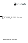
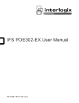
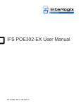
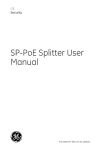
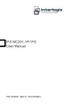
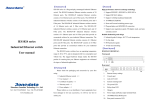
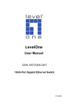
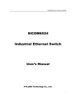
Introduction
1.3 Technical Specification
Model
1.1 Packet Contents
POE-E101
Interfaces
Thank you for purchasing PLANET POE-E101 IEEE
802.3af Power over Ethernet Extender, your Power
over Ethernet Extender package shall contains following
contents:
LAN IN
Check the contents of your package for following parts:
zz Power over Ethernet Extender x 1
LAN OUT
zz User's Manual x 1
If any of these pieces are missing or damaged, please
contact your dealer immediately, if possible, retain the
carton including the original packing material, and use
them against to repack the product in case there is a
need to return it to us for repair.
1 x 10/100Base-TX Ethernet with IEEE
802.3af PoE “Data + DC” in Auto
MDI/MDI-X, Auto-negotiation RJ-45
connector
1 x 10/100Base-TX Ethernet with IEEE
802.3af PoE “Data + DC” out Auto
MDI/MDI-X, Auto-negotiation RJ-45
connector
Power over Ethernet
PoE
Standard
IEEE 802.3af Power over Ethernet
PoE Power
Supply Type
Mid-Span / Type B
PoE Power
Output
48V DC, 270mA, Max. 13 Watts
Power Pin
Assignment
4/5(+), 7/8(-)
-1-
-3-
1.2 Key Features
Hardware Specification
zz Complies with IEEE 802.3af Power over Ethernet
Data Rate
10/100Mbps
zz Extends the range of PoE an additional 100 meters
(328ft.)
Switch
Architecture
Store-and-Forward
zz Forwards both Ethernet data and PoE power to
remote device
Switch
Throughput
148810pps@64Bytes
zz Auto-detect and protect of PoE equipment from being
damaged by incorrect installation
Latency
7.840µs
Maximum
Frame Size
1552Bytes
Flow Control
Back pressure for Half-Duplex
IEEE 802.3x Pause Frame for Full-Duplex
LED
Indicators
• 1 x PoE IN (Green)
• 1 x LAN Data (Green)
• 1 x PoE OUT (Green)
Protection
ESD (Ethernet) : 6KV (TBD)
Surge (EFT for power) : 6KV (TBD)
Dimension
(W x D x H)
94 x 70 x 26 mm
Weight
215g
zz Multiple units, daisy-chain installation support
zz No external power cable installation required
zz Compact size, Wall-mountable design
zz Plug-and-Play installation
Standards Conformance
Regulation
Compliance
FCC Part 15 Class A, CE
Standard
Compliance
IEEE 802.3 10Base-T Ethernet
IEEE 802.3u 10/100Base-TX Fast
Ethernet
IEEE 802.3af Power over Ethernet PSE
/ Mid-Span
IEEE 802.3af Power over Ethernet PD /
Mid-Span
IEEE 802.3x Flow Control
Environment
Operating
Temperature:
0 ~ 50 Degree C
Relative Humidity:
0 ~ 95% (non-condensing)
Storage
Temperature:
-40 ~ 85 Degree C
Relative Humidity:
5 ~ 95% (non-condensing)
IN Port
Connect the PoE IN port from following
802.3af PSE device through a CAT-5e/6
UTP cable:
• PoE Injector
• PoE Injector Hub
• PoE Ethernet Switch
• Previous POE-E101
OUT Port
Connect the PoE OUT port to following
802.3af PD device through a CAT-5e/6
UTP cable:
• PoE IP Camera
• PoE VoIP Phone
• PoE Wireless AP
• PoE Splitter
• Next POE-E101
2.3 LED Definition:
LED
Color Function
PoE IN Green
Lights to indicate the port is
providing 48V DC in-line power.
LNK/
ACT
Green
Lights to indicate the port is link up.
Blink: indicate that the extender is
actively sending or receiving data
over IN port.
PoE
OUT
Green
Lights to indicate the port is
providing 48V DC in-line power.
-5-
-7-
Hardware Description
Hardware Installation
2.1 Product Outlook
This product provides two different running speeds –
10Mbps, 100Mbps in the same device and automatically
distinguishes the speed of incoming connection.
This section describes the hardware features of
POE-E101. Before connecting any network device to the
POE-E101, read this chapter carefully.
3.1 Before Installation
Before your installation, it is recommended to check
your network environment. If there is any far away IEEE
802.3af devices need to power on, the POE-E101 can
provide you a way to supply power for this Ethernet
device conveniently and easily.
The POE-E101 is installed between the PSE (Power Source
Equipment) and the PD (Powered Device); it is powered
by PSE and forwards the Ethernet data and remaining
POE power to the PD. The POE-E101 doesn’t require
an external power supply and it can be installed easily
just plug and play; that means the operator does not
need to configure the POE-E101. The POE-E101 injects
power to the PDs without affecting the data transmission
performance. It offers a cost effective and quick solution
to extend power and data an additional 100m.
Power
IEEE 802.3af compliant with voltage
Requirement within 44V-56V DC
Power
2 Watts (system maximum)
Consumption
-2-
2.2 Ports Connection
Mechanical
Metal / Wall Mountable
Cable
TIA/EIA-568, Category 5/5e cable
-4-
Note
-6-
The POE-E101 can be installed with third-party
device if the device complied with IEEE 802.3af
standard.
-8-
3.2 Connect POE-E101 to the Power Source
Equipment (PSE)
There are 2 RJ-45 ports in the PoE Extender, of which
the “IN” port functions as “PoE (Data and Power)
input" and the ”OUT” port on the other side functions
as “PoE (Data and Power) output”.
3.4 Multiple PoE Extender Installation
The POE-E101 PoE Extender supports multiple units,
daisy-chain installation. They can be employed in
series for even longer distances based on remote
PoE IP Camera or PoE Wireless Access Point power
requirement.
Step 1: Connect a standard CAT-5e/6 UTP cable from
Power Source Equipment (PSE), such as
PoE Switch, PoE Injector hub and single port
PoE injector, to the “IN” port of POE-E101.
Step 1: Connect the additional CAT-5e/6 cable from
the “OUT” port of the first POE-101, the other
end of the UTP cable be used to connect to the
“IN” port of remote / next POE-E101.
Step 2: The PSE delivers both Ethernet Data and PoE
power over UTP cable to the POE-E101 and the
“PoE IN” LED will be steady on.
Step 2: The “PoE OUT” LED indicator of the first
POE-101 will be steady to shows it is providing
power to next PoE Extender.
Note
1. The PoE IN LED turn on steady green means
POE-E101 is being powered successfully with
PoE class 0.
2. If PoE IN LED does not turn on, please check
the remote PSE or the cable with a PC or a
network device to see if the cable is correct.
Or with an 802.3af device such as the target
PD to check the power injection is correct
either.
Step 3: The “PoE IN” LED on the next POE-101 will
steady on.
Step 4: Connect the additional CAT-5e/6 cable to the
remote PoE powered device to the “OUT” port
of next or third POE-E101.
-9-
- 11 -
3.3 Connect POE-E101 to the Powered
Device (PD)
300 meters
200 meters
100 meters
(11W)
(13W)
(15W)
Step 3: Connect the additional CAT-5e/6 cable that
will be used to connect to the remote Powered
Device (PD) to the “OUT” port of POE-E101.
Step 4: The “OUT” port is also the power injectors
which transmit DC Voltage to the CAT-5e/6
cable
and
transfer
data
and
power
simultaneously between the PSE and PD.
POE-E101
POE-E101
PoE IP Camera
Data + Power
PoE
PoE
100 meters
100 meters
PoE Extender
PoE
PoE Extender
PoE Extender
AC
POE-E101
100 meters
100 meters
PoE
PoE
PoE Splitter
DC
100 meters
PoE
AC
Power Line (AC)
Power Line (DC)
1
2
Step 3: Check the DIN-Rail is tightly on the track.
PoE Extender
AC
Power Line (AC)
DC
Power Line (DC)
100Base-TX UTP
Non-PoE IP Camera
PoE
100Base-TX UTP with PoE
Data
100Base-TX UTP
PoE
There are two DIN-Rail holes on the left side of the
POE-E101 that allows the converter can be easily
installed with DIN-Rail mounting. The PLANET optional
DIN-Rail mounting Kit – RKE-DIN can be order
separately. When need to replace the wall mount
application with DIN-Rail application on the POE-E101,
please refer to following figures to screw the DIN-Rail on
the converter. To hang the POE-E101, follow the below
steps:
Step 2: Lightly press the button of DIN-Rail into the
track.
Step 1: screw the DIN-Rail on the POE-E101.
POE-E101
PoE
DC
AC
DC
PoE Ethernet Switch/
Injector Hub
100 meters
Power
PoE Injector
100Base-TX UTP with PoE
1. If the connected device is not fully complying
with IEEE 802.3af standard or in-line
power device, the PoE OUT LED indicator of
POE-E101 will not be steady on.
2. According to IEEE 802.3af standard, the
POE-E101 will not inject power to the cable
if not connecting to a standard IEEE 802.3af
device.
- 10 -
100 meters
PoE
PoE Extender
200 meters
Note
POE-E101
100 meters
PoE
PoE IP Camera
Step 5: Once POE-E101 detects the existence of an
IEEE 802.3af device, the “PoE OUT” LED
indicator will be steady, ON to shows it is
providing power.
Data + Power
Power Output
100 meters
PoE Access Point
3.5 Optional - DIN-Rail mounting
0 meters
Note
1. Per POE-E101 will take 2 watts maximum
for the system itself, please check the total
power consumption of your 802.3af PD
and the POE-E101 before you make the
daisy-chain connection. If the overall power
consumption is overloaded, the local PSE
could shutdown the whole power system.
2. Per POE-E101 cable segment is limited in 100
meters CAT-5e/6 UTP wire from its IN/OUT
port to the other data end, use of any other
non standard cable or over distance could
results in unstable connection.
- 12 -
You must use the screws supplied with
the mounting brackets. Damage caused to
the parts by using incorrect screws would
invalidate your warranty.
- 13 -
- 14 -