1
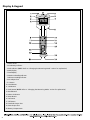
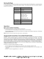
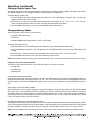
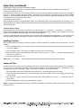
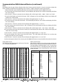
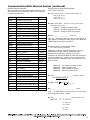
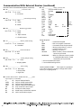
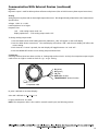
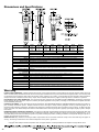
DFS-Digital Force Gauge
Instruction Manual
Contents
Congratulations on your purchase of a Shimpo DFS (Digital
Force Gauge). We trust you will enjoy many years of
professional results from your DFS for force measurement
applications.
Please read the entire instruction manual thoroughly before
initial set-up and operation; the information contained
herein will aid you in operating your Shimpo DFS safely and
with excellent results.
If you have any questions regarding our product(s), call your
local Shimpo representative or contact Shimpo directly for
assistance.
Inspection / Standard Accessories
Features and Benefits
Important Safety Instructions
Set-Up
Power
Display and Keypad
Factory Settings
Operation
How to Tare and Zero the Display
Changing the Measuring Mode
Changing Units of Measure
Setting High and Low Limits
Changing Display Update Time
Changing Memory Modes
Recalling Statistics
Setting of Filter
Communication with External Devices
Output Selection
RS232
Digimatic
Analog
Comparator
External Control Input
Overload Output
Parameter Settings
Low Battery Indication
Auto Power Off
Calibration
Troubleshooting
Dimensions and Specifications
Warranty
2
2
2
3
3
4
5
5-8
5
5
6
6
6
7
8
8
9-16
9-13
10-12
13
13
13
14-15
16
17
18
18
18-19
19
20
20
Inspection/Standard Accessories
If any damage is apparent, do not unpack the DFS. Notify
the shipping carrier immediately for damage claim
instructions. Refer to the nameplate to confirm model
number ordered and record serial number for future
reference.
Items included with the DFS are:
• AC adapter
• (4) AA batteries
• DFS output connector
• Overload protection cable
Important Safety Instructions
Always wear eye protection when testing
materials.
Attachments must be properly installed to the
force gauges (hand-tighten only! Do not use
wrenches or other tools!).
Never exceed force capacity; if “OVR 1234”
appears on the display, STOP the test immediately
to avoid permanent sensor damage.
• Plastic carrying case
Features and Benefits
The DFS offers many features and benefits, including:
• Large memory capacity (100 samples plus statistics)
enables portable data collection for multi-location
usage
• High sampling rate (1000 hz) allows peak force and
torque points to be easily captured
• Handheld and test stand mountable - allows flexibility
in multiple test set-ups, applications and fixturing
• High and low set points permit measurement of
breakaway torque in applications such as child safety
cap testing
• External tare and hold control allows hands-free
zeroing using a keyboard or foot switch
Never apply a force or load at an angle to the
force sensor.
When installing the DFS on a test stand, confirm
that the indicator unit is thoroughly secured.
When not in use over an extended period of
time, remove batteries to avoid battery terminal
corrosion.
Only use the provided AC adapter; usage of any
other adapter may damage circuitry.
Check the batteries periodically for corrosion
when using the unit under AC power; this will
avoid damage and ensure memory backup (refer
to “Low Battery Indication” section).
Do not use or store unit in extreme temperatures;
normal operating temperature is 32-113°F (045°C).
Do not use or store unit in oily, dusty, or
excessively wet areas.
Do not use any chemicals to clean the case; use
a wet, soapy cloth.
2
Set-Up
Power
Every DFS unit is shipped from the factory without the batteries (provided) installed. To install the batteries:
1. Remove the battery plate located at the bottom of the handle using a coin or appropriate screwdriver.
2. Install the (4) AA batteries, observing the proper polarity.
3. Reinsert the battery plate cover, making sure the lip engages properly before tightening.
NOTE: If AC adapter operation is preferred, refer to the “Display & Keypad” section of this manual for AC outlet
location.
3
Display & Keypad
1. Sensor Shaft
2. Low Battery Indicator
3. Peak Indicator (NOTE: Refer to “Changing the Measuring Mode” section for explanation)
4. Main Display
5. Small Display
6. Maximum Reading Indicator
7. Minimum Reading Indicator
8. AC Adapter Port
9. > Button
10. HI-LO Button
11. Unit Button
12. Peak Button (NOTE: Refer to “Changing the Measuring Mode” section for explanation)
13. Recall Button
14. Memo Set Button
15. Reset Button
16. On Button
17. Off Button
18. Overload Output Port
19. Data Output Port
20. Battery Compartment
4
Factory Settings
Each time the power is turned OFF and ON there are some parameters that the DFS will default to. Consult the section
on “Parameter Settings” to customize these default settings. The following chart reflects the default settings as
programmed by the factory:
PARAMETER
Display Update
DEFAULT FACTORY SETTING
0.125 seconds
Measuring Mode
True Peak
Auto Power Off
3 Minutes
Measurement Unit
English (Lb, Lb-I or oz-I)
Output
RS232
Baud Rate - 4800
Data Length - 8 bits
Stop Pulse - 2 bits
Data End Code - CrLF
Software Flow Control - off
External Trigger
Tare
Memory Mode
Single
Analog Output Mode On
Filter
Off
Operation
How to Tare and Zero the Display
After installing an attachment, it will be necessary to tare the DFS:
1. Press the RESET button while holding down the ON button to tare the display.
2. Press the RESET button by itself when the peak indicator is showing to zero the display. Repeat step 1 if the display
does not return to zero.
NOTE: The DFS can tare up to 50% of the remote sensor’s rated capacity.
Changing the Measuring Mode: True Peak Mode/Standard Mode
CAUTION: Depending on which of these two measuring modes is selected, the PEAK button performs two different
functions! The DFS will always display an average force when PEAK is not showing on the display. The average
measurement is based upon the display update rate chosen (see “Changing Display Update Time” section). When in the
True Peak mode, pressing the PEAK button will allow the display to scroll from average to peak “+” (compression or
clockwise torque) to peak “-” (tension or counterclockwise torque). When in the Standard mode, pressing the PEAK
button will allow the display to scroll from average to maximum display reading “+” to maximum display reading “-”.
Despite showing PEAK on the display, these are not true peak readings; they are the highest average displayed
readings since the DFS was last “tared”.
Instructions to change the Measuring Mode are as follows:
1. Press the PEAK button while holding down the ON button. The small display will exhibit “dSP”.
3. Press the PEAK button; the small display will read “PfS” and the main display will show “on” (True Peak) or “oFF”
(Standard).
3. Press the > button to toggle between “on” and “oFF”.
5
Operation (continued)
4. Press MEMO SET button to store the measuring mode and exit.
NOTE: By keeping the true peak mode “ON”, the DFS will always display the peak samples and not a maximum average.
Changing Units of Measure
By pressing the UNIT button, the DFS will scroll between English, Metric, and Newton units; once the DFS is turned OFF
the unit will default to the factory setting. Instructions to change the default unit of measure setting are as follows:
1. Press the PEAK button while holding down the ON button; the small display will indicate “dSP”.
2. Press the PEAK button three times; the main display will indicate “init” and the small display will reflect the current
default setting.
3. Each time the UNIT button is pressed, the small display will scroll between English, Metric, and Newton units.
4. Press the MEMO SET button to store the default unit setting and exit.
Setting High and Low Limits
It is possible to program high and low limits for applications requiring tolerances. Use the diagram below as a guide for setting the
limits.
Instructions to set the high and low limits are as follows:
1. Press the HI-LO button; “∆HI” will be flashing on the small display and whatever limit is already programmed will
be displayed.
2. Press the > button; the entire display will be flashing.
3. Press the HI-LO button to toggle between “+” (compression or clockwise torque) and “-” (tension or counterclockwise torque).
4. Press the > button to scroll across each digit position.
5. Press the HI-LO button to select the numerical value of each digit position.
6. Once the high limit has been programmed, press the MEMO SET button; “∇LO” will be flashing on the small
display and whatever limit is already programmed will appear on the main display.
7. To program the low limit, repeat steps 2-5.
8. Once the low limit has been programmed, press the MEMO SET button to store the set points and exit from this
function.
The unit of measure will be displayed when the measurement is within the set points. Small “arrows” (∆ or ∇) will
appear on the small display when the measurement is above or below the set points.
The unit of measure will never be displayed if the low limit is set higher than the high limit. This is because it is
impossible for the measurement to fall between the setpoints.
Set points can be referenced by pressing the HI-LO button: the first time the button is pressed the display will show the
high limit, the second time will show the low limit, and the third time will exit.
To cancel the high and low limits, both settings must be set to zero.
NOTE: A comparator output is available for “go – no go” testing (refer to “Comparator Output” section).
6
Operation (continued)
Changing Display Update Time
The display update time works with the sampling rate (1000 hz) to provide an average reading. All samples taken within
the selected update time are averaged (based on 1000 samples/sec) and displayed.
To change display update time:
1. Press the PEAK button while holding down the ON button. The small display will exhibit “dSP” and the main
display will reflect the current setting.
2. Each time the > button is pressed, the main display will scroll through “0.125”, “0.25”, “0.5”, “1.0” and “2.0”
(these correspond with the amount of time in seconds that the display will update).
3. Press the MEMO SET button to store the desired display update time and exit.
Changing Memory Modes
The DFS operates in three distinct memory modes:
• Single (on-demand memory)
• Continuous
• Standard (NOTE: Main display reflects “nonE” in this mode)
To change the memory mode:
1. Press the PEAK button while holding down the ON button; the small display will reflect “dSP”.
2. Press the PEAK button six times; “Log” will appear on the small display and the main display will reflect the current
setting.
3. Each time the > button is pressed, the main display will scroll through “SinG”, “Cont” and “nonE”.
4. Press the MEMO SET button to store the desired memory mode and exit.
NOTE: Data stored in memory can be output to an external device (see “Communication with External Devices” section).
Single and Continuous Memory Modes
The three functions performed when using either the Single or Continuous mode are:
• Storing data
• Recalling data
• Deleting data
Storing Data (Single Memory Mode)
After selecting the “SinG” mode it is possible to send one data reading into memory each time the MEMO SET button is
pressed; the small display will briefly change to an “M”. The “M” indicates that the data reading displayed has been
stored in memory. Up to one hundred data readings can be stored. “FULL” will appear on the main display if memory is
full.
Storing Data (Continuous Memory Mode)
After selecting the “Cont” mode it is possible to enter data readings continuously into memory by pressing the MEMO
SET button once. The small display will reflect a flashing “M” and data readings will be stored in memory as quickly as
the display update rate chosen (reference “Changing Display Update Time” section). Data readings will continually be
entered into memory until the MEMO SET button is pressed a second time or 100 samples have already been entered
(“FULL” will appear briefly on the main display).
Recalling Data (Single and Continuous Memory Mode)
To recall data in the memory press the RECALL button; the last data reading entered and corresponding memory position
will be flashing opposite each other on the main display. Each subsequent push of the RECALL button will scroll through
the data readings in the opposite order as they were entered. Press the RESET button to exit from memory recall.
NOTE: No data readings have been entered if “nonE” shows on the main display after pressing the RECALL button.
7
Operation (continued)
Deleting Data (Single and Continuous Memory Mode)
While recalling data (see above) it is possible to delete one data reading at a time or delete the entire memory.
To cancel one reading at a time:
Press the RECALL button to scroll through the data in memory until the undesired reading is appears on the display.
Push the > button to delete that data reading. All higher memory positions will decrement one to fill the deleted
position. If the reading being deleted is the last one in memory, then the memory position will decrement one as there
is no higher memory position to take its place.
To delete the entire memory:
After recalling the memory using the RECALL button, press the RESET button while holding down the ON button; “CLr”
will briefly appear on the main display. This indicates that all data readings have been deleted and will automatically exit
from memory recall.
Standard Memory Mode
After selecting the “nonE” mode it is possible to store the maximum “+”, maximum “-”, minimum “+”, minimum “-”,
and last reading during a sampling period. After pressing the MEMO SET button, a flashing “M” will appear on the small
display; push the MEMO SET button again to end the sampling period.
Each time the RECALL button is pressed the DFS will scroll through the readings mentioned above. It is not necessary to
clear the memory before performing the next test as they will be cancelled when the MEMO SET button is pressed.
Recalling Statistics
While recalling data from memory in either the Single or Continuous Mode it is possible to also recall statistics. To recall
statistics:
1. Press the RECALL button. The last data reading entered and memory position will be flashing opposite each other
on the main display.
2. Press the PEAK button. The maximum reading will appear on the main display.
3. Each subsequent push of the Peak button will scroll to minimum, peak “+”, peak “-”, average, standard deviation
and return to maximum.
4. Press the RESET button to exit.
NOTE: Peak “+” and peak “-” will not be displayed if the data was stored in the Single Memory Mode.
Setting of Filter
Subtle vibrations are common in many testing environments. The DFS incorporates a filtering feature that “smoothes”
the force curve by eliminating extraneous measurements caused by these outside influences. Depending on how
severely these impact the sampling, a large or small filter is available. Set a filter as follows:
1. Press the PEAK button while holding down the ON button. The small display will show “dSP”.
2. Press the PEAK button eight times. The small display will indicate “Adf” and the main display will reflect the
current setting.
3. Each time the > button is pressed, the main display will scroll through “0” (no filter), “1” (small filter) and “2”
(large filter).
4. Press the MEMO SET button to store the selection and exit.
NOTE: To determine which filter (if necessary) is needed, first attempt to test without a filter, then proceed to filter 1 and
possibly to filter 2.
8
Communication with External Devices
When operated with the proper cable, the DFS offers a variety of output and input abilities for bi-directional communication
with external devices such as computers and data loggers.
Output Selection
There are three output selections:
• RS232
• Digimatic
• None
Although there are only three output options, there are actually four outputs available; consult the chart below to
determine the proper selection for the cabling and output desired:
DESIRED OUTPUT
CABLE PART #
MAIN DISPLAY
RS232
DFS-RS232
232
Digimatic
Comparator
DFS-Digimatic
DFS-Comparator
dG
232 or nonE
Analog
DFS-Analog
232, dG, or nonE
The following chart indicates the pin outs of the DFS connector:
Connector
1. RXD
2. TXD
RS232 (Selectable)
3. CTS
4. RTS
5. REQ
5. Ext. Input
6. READY
6. HI
Digimatic*
7. CLK
7. GO
8. DATA
8. LO
9. (0±1V), always present
10. GND
External Input*
Comparator Output*
*Digimatic, External Input and Comparator Output share wires.
Instructions to select the type of output are as follows:
1. Press the PEAK button while holding down the ON button. The small display will indicate “dSP”.
2. Press the PEAK button four times. The small display will indicate “OUT” and the main display will reflect the
current setting.
3. Each time the > button is pressed, the main display will scroll through “nonE”, “dG”, “232”. NOTE: If “RS232” is
selected, please review the following section to set these specific output characteristics.
4. Press the MEMO SET button to store the selection and exit.
9
Communication With External Devices (continued)
RS232
Depending upon the type of data collection device that is being used with the DFS, it may be necessary to adjust the
factory settings mentioned at the beginning of this manual. To adjust the RS232 output characteristics:
1. Select the RS232 output (following the above instructions) but do NOT press the MEMO SET button.
2. To set the baud rate, press the HI-LO button. The small display will indicate “bPS” and the main display will reflect
the current setting.
3. Each time the > button is pressed, the main display will scroll through “9600”, “4800”, “2400” and “1200”.
4. To set the data length, press the HI-LO button; “dAT” will appear on the small display while the main display will
indicate the current setting.
5. Each time the > button is pressed the main display will toggle between “8” and “7”.
6. To set the stop pulse, press the HI-LO button. The small display will indicate “STP” and the main display will reflect
the current setting.
7. Each time the > button is pressed, the main display will toggle between “1” and “2”.
8. To set the parity, press the HI-LO button; “PRT” will appear on the small display and the main display will reflect
the current setting.
9. Each time the > button is pressed, the main display will scroll through “nonE”, “Eun” (even), “odd” (odd).
10. To set the data end code, press the HI-LO button; the small display will indicate “dEL” and the main display will
reflect the current setting.
11. Each time the > button is pressed, the main display will toggle between “Cr” and “CrLF”.
12. To set the software flow control, press the HI-LO button. The small display will indicate “fLO” and the main
display will reflect the current setting.
13. Each time the > button is pressed, the main display will toggle between “on” and “oFF”.
14. After selecting the software flow control, press the MEMO SET button to store the RS232 characteristics and exit.
Output Data Format
The following chart demonstrates the format of the data
as it is output through RS232:
1
CR
U
D
M
M
P
P
A
D
H
L
CR
1
10
2
S
LF
N
A
A
I
K
K
V
E
L
L
LF
D
9
0
*
3
T
4
A
5
T
I
T
X
N
C
T
G
V
M
M
T
A
S
A
1
2
9
0
*
6
I
7
S
8
T
k
g
9 10 11 12 13 14
I C S
CR LF
1
9
8
0
9
0
1
.
0
0
A —
9
1
5 CR LF
L —
H —
8
0
9
*
9
0
9
5 CR LF
5 CR LF
0 CR LF
1
—
—
1
T
T
—
—
1
T
E
N
1
D
*
0
0
1
LF
LF
LF
LF
LF
LF
LF
LF
LF
LF
0
0
0
0
0
2
2
0
0
—
—
1
0
CR
CR
CR
CR
CR
CR
CR
CR
CR
CR
Memory Data Output
Data may be output from memory by first pressing the
RECALL button and then pressing the MEMO SET button.
The main display will briefly indicate “oUt” to confirm that
the data has been sent. The following chart indicates the
order of the data output depending upon which memory
mode was used:
ON-DEMAND
CONTINUOUS
STANDARD
STATISTICS
STATISTICS
Units
Units
DATA
Units
DATA
Max
Max
MAX
MAX
MIN
MIN
MIN
MIN
AVG.
PKC
LAST
DEV
PKT
**END**
HLMT
LLMT
AVG
DEV
HLMT
LLMT
DATA
1 XXX
2 XXXX
3 XXXX
DATA
1 XXXX
2 XXXX
Communication With External Devices (continued)
External Control Commands
The chart below lists the ASCII Capital Characters and
their functions for controlling the DFS from a computer
or other external device:
COMMAND FUNCTION
DATA
External Control Command Descriptions
ASCII capital characters
! UNTG, UNTN, UNTL - Change UNITS to Kg, N, lb
UNTG CR... Kg(g)
UNTN CR... N
UNTL CR... lb (oz)
UNTG
Change units to g or kg
UNTN
Change units to N
UNTL
DSPN
Change units to lb or oz
Change mode to average
DSPT
Change mode to peak tension
DSPC
Change mode to peak compression
PKCL
Peak clear reset
MEMS
Display value stored in memory
! PKCL _____________________ Peak Clear
MEMC
MEMD
Last data in memory clear
Memory data output
MEMZ
Clear all data in memory
PKCL CR.... Peak reset. Same as reset from the gauge. If
edge trigger is selected for HOLD, the PC can release the
HOLD using this particular command.
MEMN
Memory location recall
CPST
Upper and lower limit set
Z
Tare
UPD
APF
Display update
Auto – power – off
1,2,3,4,5
0,3
EXS
External input setting
Z,H,N
HLD
Hold trigger mode
E,L,O,C
LOG
Memory mode setting
S,C,N
PKF
Peak fast mode
0,1
DAF
ADF
Analog output setting
Filter setting
0,1
0,1,2
D
Output display data
DATN
Output average mode data
DATT
Output tension peak data
DATC
Output compression peak data
LIST
AB
Gauge’s present state
Stop continuous data output
BB
Continuous data output request
BC
Model name confirmation request
BD
Units confirmation request
! DSPN, DSPT, DSPC - Change to average, peak tension,
peak compression mode
DSPN CR... Change to average mode
DSPT CR... Change to peak tension mode
DSPC CR... Change to peak compression
! MEMS, MEMC, MEMD, MEMZ, MEMN
(five control memory commands)
MEMS CR.... with this command if gauge is set in the
ON-DEMAND (single) mode, it sends back to the
computer the word SING. If gauge is set in the
continuous or standard mode then when this command
is sent and the gauge’s memory starts, it sends back to
PC the word STA. If memory stops, the word STP is sent
back to the PC.
MEMC CR.... Last DATA in memory to clear
MEMD CR ....Memory DATA recall
MEMZ CR ... Clear all DATA in memory
MEMN CR ....Memory location recall
! CPST _________________________Comparator Setting
CPST 0 0000 0 0000 CR
SIGN
UPPER
LIMIT
SIGN
LOWER
LIMIT
Example: CPST 1234-0123 CR
SPACE
need 4-digit # (fill with zeros)
! Z _________________________________ TARE
Z CR .... To TARE. Works the same way as if it were done
thru the gauge i.e SHIFT + ZERO.
! UPD ________________________ Display Update Time
UPD # CR
# = 1: 0.125 sec.
2: 0.25 sec.
3: 0.5 sec.
4: 1 sec.
5: 2 sec.
11
Communication With External Devices (continued)
External Control Command Descriptions (continued)
! APF ____________________ Auto-Power-Off
APF # CR
# = 0: none
3: 3 minutes
! EXS ________________________External Input Setting
EXS # CR
# = Z: TARE
H: HOLD
N: NONE
! HLD _________________ HOLD Trigger Mode
HLD # CR
# = E: EDGE
L: LEVEL
O: Open Contact
C: Closed Contact
! LoG __________________ Memory Mode Setting
LoG # CR
# =S: Continuous
N: Standard
! PKF __________________ PEAK Fast Mode
PKF # CR
# = 0: OFF
1: ON
! DAF __________________ Analog Output Setting
DAF # CR
#=
0: 1 msec
1: Display update
! ADF __________________ Filter Setting
ADF # CR
# = 0: None filter
1: Normal filter
2: High filter
! D, DATN, DATT, DATC, AB, BB, BC, BD _______Data
output request (8 commands)
D
DATN
DATT
DATC
AB
BB
BC
BD
12
CR ....Output displayed DATA
CR ....Output average mode DATA
CR ....Output tension PEAK DATA
CR ....Output compression PEAK DATA
CR ....Stop continuous data output
CR ....Continuous data output
CR ....Model name confirmation request
CR ....Unit's confirmation request
! LIST ____________ Gauge’s present state
LIST
MDL
UNITS
DSPM
DSPT
PKFST
DAFST
ADFIL
OFFT
232C
232C
CP
HLMT
LLMT
ET
ET
LOG
CR (Command from PC)
DFS-100
lb
NORMAL
0.125
ON
ON
NONE
NONE
4800
B8
S2
PN
CR LF
X OFF
ON
50.00
- 10.00
HOLD
LEVEL OPEN
CONTINUE
Typical
gauge
response
Gauge Response
OK
ERRO
ERR1
ERR2
ERR3
ERR7
IN HOLD
IN MEMORY
....Command accepted
....Did not recognize command*
....Command cannot be processed*
....Wrong nomenclature, i.e N,S,C*
....Communications error*
....Memory unit error**
....When in HOLD, certain commands
cannot be processed.
....When in continuous memory mode
or standard mode (active), certain
commands can be processed.
* Check command and resend
** See troubleshooting section
UNITS CHANGE DISABLE .... This output is transmitted
to PC when someone is trying to change UNITS while
memory is accepting DATA.
Communication With External Devices (continued)
Digimatic
Digimatic output is used for Mitutoyo data collectors and printers (refer to RS232 memory data output instructions).
Analog
Analog output is very linear and can have a high response time (1mS). This voltage is directly related to the unit of measurement.
Specifications:
Voltage: -1VDC~0~+1VDC
Load Impedance: 2K or higher
Response Time:
1mS - with analog output mode “on”
display update time - with analog output mode “oFF”
To change analog output mode:
1. Press the PEAK button while holding down the ON button; “dSP” will appear on the small display.
2. Press the PEAK button seven times. The small display will indicate “dAf” and the main display will reflect the
current setting.
3. Each time the > button is pressed, the main display will toggle between “on” and “oFF”.
4. Press the MEMO SET button to store analog output mode and exit.
Comparator
Once high and low limits have been set (refer to “Setting High and Low Limits” section), the comparator output may be
used to turn on a light or sound an alarm for “go - no go” testing.
HI (yellow)
GO (green)
LO (red)
GND (black or blue)
TRIGGER INPUT (white or brown)
Comparator cable
HI point is defined as: HI<Data (display)
OK or GO is defined as: LO < Data < HI
LO point is defined as: LO>Data
NOTE: The comparator cable is also used for external control input (see following section).
13
Communication With External Devices (continued)
External Control Input
NOTE: To activate the comparator cable, either “RS232” or “nonE” needs to be selected under outputs.
Using external control input makes it possible to remotely tare or hold the display. The following diagram indicates the pin
outs of the DFS:
Input: 5VDC, 0.3mA
Pulse width: >25ms
To select external input:
1. Press the PEAK button while holding down the ON button. The small display will indicate “dSP”.
2. Press the PEAK button five times; “ET” will appear on the small display while the main display will reflect the current
setting.
3. Each time the > button is pressed, the main display will scroll through “tArE”, “HoLd”, “nonE”.
4. A) If “nonE” or “tArE” is desired, push the MEMO SET button to store the selection and exit.
B) If the “HoLd” feature is desired, push the HI-LO button to set additional characteristics; the small display will
indicate “EL” and the main display will reflect the current setting.
5. Each time the > button is pressed, the main display will toggle between “EdG”(edge trigger) and “LEu”(level trigger).
6. Push the HI-LO button after selecting the type of trigger; the small display will indicate “OPC” and the main display
will reflect the current setting.
7. Each time the > button is pressed, the main display will toggle between “oPn”(open) and “CLS” (closed).
8. Push the MEMO SET button to store the type of trigger and exit.
14
Communication With External Devices (continued)
External Tare
To tare, short pins 5 and 10 for at least 25mS.
External Hold
Choose edge or level trigger and also OPEN or CLOSED condition.
Level trigger: OPEN
Display holds present value when switch opens.
Level trigger: CLOSED
Display holds present value when switch closes.
Edge trigger: OPEN
Display holds present value after switch opens
until it is reset.
Edge trigger: CLOSED
Display holds present value after switch closes
unitl it is reset.
HOLD cannot be released from an external source in the edge trigger mode. To release it press RESET. Level mode
can be released externally.
15
Communication With External Devices (continued)
Overload Output
The DFS possesses an overload output feature (DFS-CTRLCABLE) to protect the load cell or torque sensor. When the load
exceeds 150% of its capacity, an open collector transistor turns ON (there are two OC NPN transistors, one for tension and
one for compression). The output of these transistors can be used as an alarm or to stop a process, thus protecting the
remote sensor or the sample under test. See “Display and Keypad” section for the location of the overload output port.
TENSION
COMPRESSION
COM
Both transistors can handle up to 28VDC, 5 mA.
NOTE: This output is always active, therefore no parameter selection is necessary.
16
Parameter Settings
The DFS will default to certain parameters when power is turned OFF and ON. To access the parameter settings:
1. Press the PEAK button while holding down the ON button; the small display will indicate “dSP”.
2. Each time the PEAK button is pressed, the DFS will scroll through each of the parameters.
3. Press the RESET button to exit.
See the chart below for the location of descriptions of the options within each parameter.
DESCRIPTION
DISPLAY
OPTIONS
Display Update Time
(see page 6)
(in seconds)
0.125, 0.25, 0.5, 1, 2
Measuring Mode
(see page 5)
on, oFF
Auto Power Off
(see page 18)
nonE, 3
Measurement Units
(see page 5)
English, Metric, or Newton
Lb(oz), Kg(g), N
Output Type
(see page 9-13)
nonE, dG, 232C
External Control Input
(see page 14-15)
nonE, tArE, HoLd
Memory Mode
(see page 7)
nonE, SinG, Cont
Update time for
Analog Output
(see page 13)
on(1ms), oFF(display update time)
Filter
(see page 8)
0, 1, 2
17
Low Battery Indication
The batteries should be changed when “LO BAT” appears on the display.
NOTE: Parameters and data in memory can be saved if the AC adapter is plugged in and the DFS is left ON before
removing the batteries.
Auto Power Off
The DFS incorporates a selectable auto power off feature to protect the life of the batteries. If no buttons are pressed
or the display has not changed for a period of three minutes, the DFS will automatically shut off. This feature is inactive
if the DFS is being used with the AC adapter or if it is in calibration mode. To engage or disengage the auto power off
feature:
1. Press the PEAK button while holding down the ON button; the small display will indicate “dSP”.
2. Press the PEAK button two times. The small display will indicate “Off” and the main display will reflect the current
setting.
3. Each time the > button is pressed the main display will toggle between “3” and “nonE”.
4. Press the MEMO SET button to store the auto power off selection and exit.
Calibration
Any DFS can be calibrated in the field. The DFS are very easy to calibrate with metric weights, but the torque sensors
require a “calibration wheel”.
Required items for DFS calibration:
• Appropriate calibration weight (see following table)
• Proper attachment for applying the weight to the DFS (either tension or compression)
• Secure mounting stand that will not introduce vibration
Instructions to calibrate a remote load cell are as follows:
1. Mount the DFS to the stand.
2. Secure the attachment to the DFS.
3. Make sure the power on the DFS is turned OFF.
4. While holding down the MEMO SET button, press the ON button and hold until the main display shows “CAL”.
The small display will reflect the two-digit code that corresponds with the capacity (see following calibration
table).
5. Press the MEMO SET button. The capacity of the DFS will appear on the main display; please move on to step 6.
If the DFS did not show the correct model (code), use the > button to select the proper code for the remote
sensor (see the following table).
6. Press the MEMO SET button. The small display will show “PLS”. Pressing the > button will toggle the small display
“MNS” and “PLS”. If calibrating under a compression load choose “PLS”. If calibrating under a tension load
choose “MNS”.
NOTE: Default setting is one direction calibration.
7. Press the MEMO SET button. The minimum indicator will appear and the main display will reflect a hexadecimal
number that has no relevance to the user.
8. Confirm that there is no load (except for the attachment) since the DFS is ready for zero point calibration. Press
the MEMO SET button. The small display will exhibit “SCN” and blink for about 12 seconds until the maximum
indicator appears.
9. Gently place the proper calibration weight (see the following table) on the load cell and confirm that it is steady.
Press the MEMO SET button to begin full scale calibration. The "SCN" will flash for about 18 seconds until the
small display shows “ENd”.
10. “ERR” will appear on the display if the calibration failed. Turn the power off and repeat the entire procedure.
11. After “ENd” appears, press the OFF button to end the calibration process.
18
Calibration (continued)
MODEL
DFS-0.5 (R)
SELECT NUMBER
00
DISPLAY
0.2
CALIBRATION WEIGHT
200g
DFS-1 (R)
01
0.5
500g
DFS-2 (R)
02
1.0
1000g
DFS-5 (R)
03
2.0
2.0kg
DFS-10 (R)
04
5.0
5.0kg
DFS-20 (R)
DFS-50 (R)
05
06
10.0
20.0
10.0kg
20.0kg
DFS-100 (R)
07
50.0
50.0kg
Please call Shimpo for information on additional sensors.
Troubleshooting
The following are general checkpoints; please call your local Shimpo representative or contact Shimpo Instruments directly for
further assistance.
The DFS does not turn on:
• Check all electrical components (power source … battery or power cord)
Error Codes are displayed:
• If any error codes appear on the display, turn power OFF and then ON
• If error code remains, see table below:
DISPLAY
CONDITION
ACTION
EE PROM reading error
Press RESET; unit will default to
factory settings
Memory data error
Press RESET to clear memory
Calibration error
Press RESET and repeat calibration
procedure
Memory unit error; occurs if the
measurement unit (lb, Kg, N) is
changed while entering data into
memory
Overload condition –possible
load cell damage
Change measurement units or clear
memory
Remove excessive load; if the display
does not return to normal operation,
send unit in for repair
19
Dimensions and Specifications
MODELS
CAPACITY
RESOLUTION
DFS-0.5
DFS-0.5R
8 oz
200 g
2N
DFS-1
DFS-1R
16 oz
500 g
5N
DFS-2
DFS-2R
2 lb
1000 g
10 N
0.01 oz
0.1 g
DFS-5
DFS-5R
5 lb
2 Kg
20 N
0.001 lb
DISPLAY
MEASURING MODE
DISPLAY UPDATE
SAMPLING RATE
TEMPERATURE COEFFICIENT
OUTPUTS
OVERLOAD CAPACITY
COMPARATOR OUTPUT
(Set Points)
OVERLOAD OUTPUT
TARE & HOLD CONTROL
MEMORY
POWER
AUTO POWER SHUT-OFF
OPERATING TEMP RANGE
DIMENSIONS/WEIGHT
DFS-20
DFS-20R
20 lb
10 Kg
100 N
DFS-50
DFS-50R
50 lb
20 Kg
200 N
0.01 lb
1g
0.001 Kg
0.001 N
ACCURACY
DFS-10
DFS-10R
10 lb
5 Kg
50 N
DFS-100
DFS-100R
100 lb
50 Kg
500 N
0.1 lb
0.01 Kg
0.01 N
0.1 N
±0.2% FS + 1/2 digit at 23°C
4-Digit LCD, 11.5 mm High with various indicators including Low Battery Indication and minus sign for Tension.
Average, Peak Compression, Peak Tension (selectable)
125 ms, 250 ms, 1 sec, 2 sec (selectable)
Average Mode: 125 ms, 250 ms, 1 sec, 2 sec
Zero: ±0.02% FS/°C (max.),
Peak Mode: 1 ms, 125 ms, 250 ms, 1 sec, 2 sec
Span:±0.015% of reading/°C (max.)
1. RS232C
2. Digimatic: (works with Mitutoyo's printer model DP-1HS)
3. Analog: (±1VDC with load impedance of 2K or higher and tare function capability.)
200% of FS
Three open collector NPN transistors for HI, GO, and LO (28VDC, 7 ma max.)
Two open collector NPN transistors one for Tension and one for Compression (28VDC, 5 ma max.)
Relay contact (selectable)
Holds 100 samples plus statistics (MAX, MIN, AVG, and Standard Deviation)
4 - AA Alkaline batteries. Last approx. 20hrs. in continuous operation or AC Adapter for continuous use (6VDC, 200 ma)
Selectable (3 minutes if there is no activity)
32 - 113°F (0 - 45°C)
3"W x 1.77"H x 9.72"L (76 x 45 x 247)mm
/1.2 lbs. (550 g)
ACCESSORIES (Included)
Batteries, carrying case, overload output cable, AC adapter, 6 adapters (flat head, hook, chisel, notched head, cone &
extension rod)
ACCESSORIES (Available)
Test stands, RS232C cable, Digimatic, analog and comparator output cables.
Warranty
LIMITED EXPRESS WARRANTY: Shimpo Instruments warrants, to the original purchaser of new products only, that this product shall be free from
defects in workmanship and materials under normal use and proper maintenance for one year from the date of original purchase. This warranty shall
not be effective if the product has been subject to overload, misuse, negligence, or accident, or if the product has been repaired or altered outside of
Shimpo Instruments’s authorized control in any respect which in Shimpo Instruments’s judgment, adversely affects its condition or operation.
DISCLAIMER OF ALL OTHER WARRANTIES: The foregoing warranty constitutes the SOLE AND EXCLUSIVE WARRANTY, and Shimpo Instruments
hereby disclaims all other warranties, expressed, statutory or implied, applicable to the product, including, but not limited to all implied warranties
of merchantability and fitness.
LIMITATION OF REMEDY: Under this warranty, Shimpo Instruments’ SOLE OBLIGATION SHALL BE TO REPAIR OR REPLACE the defective product or
part, at Shimpo Instruments’ option. Shimpo Instruments reserves the right to satisfy warranty obligation in full by reimbursing Buyer for all
payments made to Shimpo Instruments, whereupon, title shall pass to Shimpo Instruments upon acceptance of return goods. To obtain warranty
service, Purchaser must obtain Shimpo Instruments’s authorization before returning the product, properly repackaged, freight pre-paid to Shimpo
Instruments.
INDEMNIFICATION & LIMITATION OF DAMAGES: Buyer agrees to indemnify and hold Shimpo Instruments harmless from and against all claims and
damages imposed upon or incurred arising, directly or indirectly, from Buyer’s failure to perform or satisfy any of the terms described herein. In no
event shall Shimpo Instruments be liable for injuries of any nature involving the product, including incidental or consequential damages to person or
property, any economic loss or loss of use.
MERGER CLAUSE: Any statements made by the Seller’s representative do not constitute warranties except to the extent that they also appear in
writing. This writing constitutes the entire and final expression of the parties’ agreement.
Copyright© Nidec-Shimpo America Corporation 2001. All rights reserved. Product specifications are subject to change without notice.
20