1
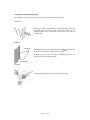
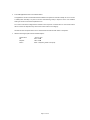
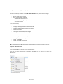
System User Manual
Sontay® SonNet Radio Sensor System
User Manual
Version 1.8
June 2011
Page 1 of 45
Audience
This manual is intended for specifiers, users and installers of the Sontay® SonNet radio sensor system.
Content
This manual provides a complete reference for the Sontay® SonNet radio sensor system.
Related Documents
®
The Sontay SonNet radio sensor system Site Survey Kit Quick Start Guide
The Sontay® SonNet radio sensor system Site Survey Kit Manual
The Sontay® SonNet radio sensor system Quick Start Guide
The Sontay® SonNet radio sensor system product datasheets
Page 2 of 45
Table Of Contents:
Overview .................................................................................................................................................. 4
Environmental .......................................................................................................................................... 4
Battery Fitting and Replacement .............................................................................................................. 4
Disposal of Batteries ................................................................................................................................. 4
Battery Powered Nodes............................................................................................................................ 5
24V Powered Routers ............................................................................................................................... 7
The System Receiver................................................................................................................................. 9
The Radio Network ................................................................................................................................. 11
Network Planning Considerations ............................................................................................ 12
The Radio System ................................................................................................................................... 14
Security................................................................................................................................................... 14
How the Self‐Healing Tree Network Is Formed ...................................................................................... 14
Propagation Of Radio Signals In Buildings .............................................................................................. 15
FAQs ....................................................................................................................................................... 16
Configuration & Monitoring Software .................................................................................................... 18
Important – Windows 7 Users.................................................................................................. 18
Installing the CMS .................................................................................................................... 20
Starting CMS ............................................................................................................................ 23
Importing a Saved Layout......................................................................................................... 24
The CMS Desktop Environment ............................................................................................... 25
Logging On as an Administrator ............................................................................................... 26
Changing the Administrator Password ..................................................................................... 26
Auto Configuration Mode ........................................................................................................ 27
Listing Devices .......................................................................................................................... 28
Changing Device Labels ............................................................................................................ 29
Creating Analogue Output Channel Mapping .......................................................................... 30
Viewing Device Properties ....................................................................................................... 31
Changing Device Configurations .............................................................................................. 33
Configurable Parameters.......................................................................................................... 33
Authorising a new node ........................................................................................................... 34
Removing a node from the network ........................................................................................ 34
Using the Graphical Map Display ............................................................................................. 35
Setting The Map Display Background Image ............................................................................ 35
Adding Devices to the Map Display ......................................................................................... 36
Icon Plan................................................................................................................................... 36
Device Status ............................................................................................................................ 37
Link Status ................................................................................................................................ 37
Auto Updating .......................................................................................................................... 38
Manual Refreshing Of Data ...................................................................................................... 38
Communications Log ................................................................................................................ 39
Configuration Log ..................................................................................................................... 39
Configuration Log ..................................................................................................................... 40
Configuration Log ..................................................................................................................... 41
Using CMS To Document A Wireless Network ......................................................................... 41
Saving and Opening Layouts .................................................................................................... 41
Receiver Print Preview ............................................................................................................. 42
Commissioning A SonNet System: A Step‐By‐Step Guide ...................................................................... 43
Best Practise Points ................................................................................................................................ 45
Page 3 of 45
Overview
The wireless nodes are based on direct‐sequence spread spectrum communication in the 2.4 ‐ 2.5GHz band,
compliant with IEEE 802.15.4‐2006.
All nodes have a unique MAC address, equivalent to a unique serial number.
All nodes have a PCB‐mounted on/off switch or jumper.
All nodes retain their configuration properties across a power failure.
Environmental
•
•
•
•
Storage temperature range of ‐10 to +80°C
Storage relative humidity range of 0 to 90% (non‐condensing).
Ambient (operating) temperature range of ‐10°C to +70°C
Ambient (operating) relative humidity range of 0 to 90%, (non‐condensing).
Battery Fitting and Replacement
When a battery is installed, or when it is replaced, observing the correct polarity is very important. Fitting
the battery incorrectly may result in permanent damage to the sensor.
Recommended batteries are 3.6Vdc 2.4Ah AA size Lithium‐Thionyl Chloride types for space housing sensors,
or 3.6Vdc 2.1Ah 2/3 A size Lithium‐Thionyl Chloride types for plant housing sensors, and are not
rechargeable.
This type of battery should be stored in a clean, cool (not exceeding +30°C), dry and ventilated area.
Disposal of Batteries ‐ Warning! Fire, Explosion And Burn Hazard
Disposal of Batteries ‐ Warning! Fire, Explosion and Burn Hazard.
Do not short‐circuit, crush, disassemble, heat above 100°C (212°F), incinerate, or expose the battery
contents to water. Do not solder directly to the cell.
All batteries must be disposed of in accordance with EC Directive 2006/66/EC, amended by EU Directive
2008/12/EC.
Page 4 of 45
Battery Powered Nodes
Battery powered sensor nodes are used in conjunction with the Sontay® RF‐RX20 or RF‐RX40 receiver units,
and if required (depending on installation topography), Sontay® RF‐RS series of routers. Data is transmitted
back to the receiver at configurable time intervals, or on a configurable change in measured value. Each
sensor retains these configurations if the battery becomes discharged or requires replacement.
The sensors automatically find the best path back to the receiver, which may be directly to the receiver or
via “parent” routers.
To power a battery powered node, jumper J400 must be fitted. To switch off, remove J400.
Battery powered nodes are available in 4 formats:
•
•
•
•
Space mounting temperature, with setpoint and momentary switch options
Space mounting RH&T, with setpoint and momentary switch options
Plant mounting temperature
Plant mounting RH&T
Space Mounting Specification:
Radio Output:
Frequency
2.4GHz
16 channels, automatically selected, direct‐sequence spread spectrum
Compliance
IEEE 802.15.4‐2006
Aerial Characteristics:
Gain
1.2dBi
VSWR
1.5:1
Data Encryption:
AES 128
Power Output:
0dBm
Accuracy:
Temperature
±0.3°C
Optional RH
±3% RH
Battery Type:
3.6V AA 2.4Ah Li‐SOCl2, non‐rechargeable
Battery Life:
>3 years (depending on configuration)
Housing:
Material:
ABS (flame retardant)
Dimensions:
85 x 85 x 23mm
Environmental:
Operating:
Temperature:
‐10°C to +50°C
RH:
0 to 90%, non‐condensing
Storage:
Temperature:
‐10°C to +80°C
RH:
0 to 90%, non‐condensing
Country of origin:
UK
Refer to product datasheets for installation instructions.
Page 5 of 45
Plant Mounting Specification:
Radio Output:
Frequency
2.4GHz
16 channels, automatically selected, direct‐sequence spread spectrum
Compliance
IEEE 802.15.4‐2006
Aerial Characteristics:
Gain
2.0dBi
VSWR
2:1
Data Encryption:
AES 128
Power Output:
0dBm
Accuracy:
Temperature
±0.3°C
Optional RH
±3% RH
Battery Type:
3.6V 2.1Ah 2/3 A Li‐SOCl2, non‐rechargeable
Battery Life:
>3 years (depending on configuration)
Housing:
Material:
ABS (flame retardant type VO)
Dimensions:
55mm x 90mm dia.
Mounting:
Holes 4mm spaced 85mm apart
Protection:
IP65
Environmental:
Operating:
Temperature:
‐10°C to +50°C
RH:
0 to 90%, non‐condensing
Storage:
Temperature:
‐10°C to +80°C
RH:
0 to 90%, non‐condensing
Country of origin:
UK
Temperature Sensor Types:
Duct
Outside air
Outside air with solar radiation shield
Immersion
Strap‐on
Flying lead
Refer to product datasheets for installation instructions.
Part Codes: Battery Powered Space Housing Nodes:
•
•
•
•
•
•
•
•
RF‐RS‐T‐911 ‐ Temperature sensor
RF‐RS‐T‐911‐SP ‐ Temperature sensor c/w setpoint knob
RF‐RS‐T‐911‐MS ‐ Temperature sensor c/w momentary switch
RF‐RS‐T‐911‐SP‐MS ‐ Temperature sensor c/w setpoint knob & momentary switch
RF‐RS‐R‐911 ‐ RH&T sensor
RF‐RS‐R‐911‐SP ‐ RH&T sensor c/w setpoint knob
RF‐RS‐R‐911‐MS ‐ RH&T sensor c/w momentary switch
RF‐RS‐R‐911‐SP‐MS ‐ RH&T sensor c/w setpoint knob & momentary switch
Page 6 of 45
Part Codes: Battery Powered Plant Housing Nodes:
•
•
•
•
•
•
•
RF‐RS‐T‐522 – Duct temperature sensor
RF‐RS‐T‐531 – OAT temperature sensor
RF‐RS‐T‐532 – OAT + radiation shield temperature sensor
RF‐RS‐T‐541 – Immersion temperature sensor
RF‐RS‐T‐551 – Strap‐On temperature sensor
RF‐RS‐T‐555 – Flying Lead temperature sensor
RF‐RS‐R‐522 – Duct RH&T sensor
24V Powered Routers
24V powered routers are used in conjunction with the Sontay® RF‐RX20 or RF‐RX40 receiver units, and RF‐
RR series of battery powered radio sensors, and are used to route signals from battery powered nodes and
other routers to the receiver module, where the signal strength of a direct path is not sufficient for reliable
communications. NB Each router can support a maximum of 16 “children”, which can consist of a maximum
of 8 battery powered nodes and 8 routers, or up to 16 routers if there are no battery powered nodes.
Consideration should be given on network planning for redundancy in case of router failure or damage.
Data is transmitted back to the receiver at configurable time intervals, or on a configurable change in
measured value. Each sensor retains these configurations if the battery becomes discharged or requires
replacement. Routers automatically find the best path back to the receiver, which may be directly to the
receiver or via other “parent” routers.
To power a router, jumper J200 must be fitted. To switch off, remove J200.
24V powered nodes are available in 5 formats:
•
•
•
•
•
Space mounting temperature, with setpoint and momentary switch options
Space mounting RH&T, with setpoint and momentary switch options
Plant mounting router, no sensor functions
Plant mounting temperature
Plant mounting RH&T
Space Mounting Specification:
Radio Output:
Frequency
2.4GHz
16 channels, automatically selected
Direct‐sequence spread spectrum
Compliance
IEEE 802.15.4‐2006
Aerial Characteristics:
Gain
1.2dBi
VSWR
1.5:1
Data Encryption:
AES 128
Power Output:
+10dBm
Accuracy:
Temperature
±0.3°C
Optional RH
±3% RH
Power Supply:
24Vac/dc
Housing:
Material:
ABS (flame retardant)
Dimensions:
85 x 85 x 23mm
Page 7 of 45
Environmental:
Operating:
Temperature:
RH:
Storage:
Temperature:
RH:
Country of origin:
‐10°C to +50°C
0 to 90%, non‐condensing
‐10°C to +80°C
0 to 90%, non‐condensing
UK
Refer to product datasheets for installation instructions.
Plant Mounting Specification:
Radio Output:
Frequency
2.4GHz
16 channels, automatically selected, direct‐sequence spread spectrum
Compliance
IEEE 802.15.4‐2006
Aerial Characteristics:
Gain
2.0dBi
VSWR
2:1
Data Encryption:
AES 128
Power Output:
+10dBm
Accuracy:
Temperature
±0.3°C
Optional RH
±3% RH
Power Supply:
24Vac/dc
Housing:
Material:
ABS (flame retardant type VO)
Dimensions:
55mm x 90mm dia.
Mounting:
Holes 4mm spaced 85mm apart
Protection:
IP65
Environmental:
Operating:
Temperature:
‐10°C to +50°C
RH:
0 to 90%, non‐condensing
Storage:
Temperature:
‐10°C to +80°C
RH:
0 to 90%, non‐condensing
Country of origin:
UK
Temperature Sensor Types:
Duct
Outside air
Outside air with solar radiation shield
Immersion
Strap‐on
Flying lead
Refer to product datasheets for installation instructions.
Page 8 of 45
Part Codes: 24V Powered Space Housing Routers:
•
•
•
•
•
•
•
•
RF‐RR‐T‐911 – Router temperature sensor
RF‐RR‐T‐911‐SP ‐ Router temperature sensor c/w setpoint knob
RF‐RR‐T‐911‐MS ‐ Router temperature sensor c/w momentary switch
RF‐RR‐T‐911‐SP‐MS ‐ Router temperature sensor c/w setpoint knob & momentary switch
RF‐RR‐R‐911 ‐ Router RH&T sensor
RF‐RR‐R‐911‐SP ‐ Router RH&T sensor c/w setpoint knob
RF‐RR‐R‐911‐MS ‐ Router RH&T sensor c/w momentary switch
RF‐RR‐R‐911‐SP‐MS ‐ Router RH&T sensor c/w setpoint knob & momentary switch
Part Codes: 24V Powered Plant Housing Routers:
•
•
•
•
•
•
•
•
RF‐RR ‐ Router
RF‐RR‐T‐522 – Router duct temperature sensor
RF‐RR‐T‐531 – Router OAT temperature sensor
RF‐RR‐T‐532 – Router OAT + radiation shield temperature sensor
RF‐RR‐T‐541 – Router immersion temperature sensor
RF‐RR‐T‐551 – Router strap‐On temperature sensor
RF‐RR‐T‐555 – Router flying Lead temperature sensor
RF‐RR‐R‐522 – Router duct RH&T sensor
The System Receiver
®
The Sontay RF‐RX20 or RF‐RX40 receiver collects data from all other devices on the radio network,
including measurements from sensors, link quality for all links formed in the network, battery levels for all
battery powered devices, hours run for all devices and the current status of all devices. NB Each receiver can
support a maximum of 16 “children”, which can consist of a maximum of 12 battery powered nodes and 4
routers, or up to 16 routers if there are no battery powered nodes.
A USB socket is provided for connection to a PC or laptop running the Sontay SonNet CMS software.
Receivers are available in 2 formats:
•
•
RF‐RX20 ‐ 20 x 0‐10Vdc analogue outputs
RF‐RX40 ‐ 40 x 0‐10Vdc analogue outputs
If a 20 output receiver is installed, and further outputs are subsequently required, a separate “daughter”
PCB (RF‐DB20) with 20 extra outputs can be added, without having to replace the existing receiver.
Receiver Specification:
Radio Output:
Frequency
2.4GHz
16 channels, automatically selected
Direct‐sequence spread spectrum
Compliance
IEEE 802.15.4‐2006
Aerial Characteristics:
Gain
2.0dBi
VSWR
2:1
Data Encryption:
AES 128
Power Output:
+10dBm
Page 9 of 45
Analogue Outputs:
RF‐RX20 20 x 0‐10Vdc analogue outputs @10mA max. each
RF‐RX40 40 x 0‐10Vdc analogue outputs @10mA max. each
Output ranges:
Temperature
‐10°C to +70°C
RH
0% to +100%
Setpoint
0% to +100%
Switch
0Vdc = OFF, 10Vdc = ON
Power Supply:
24Vac/dc
Housing:
DIN Rail
W203 x H104 x D38mm (excluding aerial)
Environmental:
Operating:
Temperature:
‐10°C to +50°C
RH:
0 to 90%, non‐condensing
Storage:
Temperature:
‐10°C to +80°C
RH:
0 to 90%, non‐condensing
Country of origin:
UK
Refer to product datasheets for installation instructions.
Part Codes:
•
•
•
•
•
•
RF‐RX20 ‐ Receiver c/w 20 x 0‐10Vdc outputs
RF‐RX40 ‐ Receiver c/w 40 x 0‐10Vdc outputs
RF‐DB20 ‐ 20 x 0‐10Vdc output expansion daughter board for RF‐RX20
RF‐AERIAL – Replacement whip aerial
RF‐AERIAL‐2 – 2m coaxial cable extension
RF‐AERIAL‐5 – 5m coaxial cable extension
Page 10 of 45
The Radio Network
A Sontay® SonNet radio system is comprised of a receiver, battery powered sensoors and permanently
powered routers.
Routers, though permanently powered, can also have sensing elements, accomplishhing both router and
sensors functions. Routers and sensors can either communicate directly with the rreceiver or via other
routers. Routers are required to be permanently powered as they need to stay “awakee” at all times to allow
signals from “child” nodes to be instantly forwarded to their “parent” nodes. Battery ppowered sensors only
“wake” for very short periods to send data.
In the schematic above, rrouters R2 to R7 have
5 children each, all batteery powered sensors.
Their parent is the receiiver. Router R1 has 6
children and R8 has 4 chhildren, giving a total
number of network devvices of 50, including
the receiver.
The receiver can support a maximum of 16 directly connected “child” devices, of wwhich only 12 can be
battery powered nodes, plus up to 4 routers.
Routers can support a maximum of 16 directly connected “child” devices, of which oonly 8 can be battery
powered nodes, plus up to 8 routers.
There can bbe a maximum depth
of 8 layers of routers in a
network annd a maximum of 50
nodes per nnetwork with the RF‐
RX series off receivers.
Page 11 of 45
Note that battery powered devices can only route their signals to the receiver directlly or through routers,
and not through other battery powered devices.
When planning a SonNet radio network, it is recommend that the Sontay® SonNet Sitte Survey Kit be used.
This easy‐to‐use package allows installers to test signal strengths between locationss required for battery
powered sensors and the receiver prior to installing the full system. It can also identifyy whether routers are
needed to ensure reliable communications between all devices on the network backk to the receiver. This
removes any guesswork from planning a system and allows the installer to order exactly and only the
devices required.
®
®
See the Sontay SonNet radio sensor system Site Survey Kit Quick Start Guide and The Sontay SonNet radio
sensor system Site Survey Kit Manual for full details.
Network Planning Considerations
When planning a SonNet radio system, it is always worth considering the placement oof routers, and should
be capable of handling the consequences of a router failing or being damaged.
Example:
Consider a network with a requirement for 16 EDs:
1. At least one rouuter is required, as 16
directly connected EDDs will exceed the
maximum limit of 12. Four EDs will be
orphaned.
2. A single router (R1) will work, but
gives no redundancy if thhe router should fail.
Page 12 of 45
3. Optimal networrk uses 2 routers, R1
and R2.
4. If either of thhe routers fail, the
network can still be m
maintained, as the 2
orphaned EDs can re‐rroute via the other
router.
Page 13 of 45
The Radio System
The radio system used by the Sontay SonNet devices is divided into 3 sections or ‘layers’.
1. The radio layer is where physical control of the radio signal is done. This conforms to international
standard 802.15.4, and determines the frequency of the radio signals, the number of ‘channels’ available
for use, the bandwidth and power level of the signal etc. There are 16 channels available, and the best
one is automatically selected by the receiver. The frequencies used are in the ISM (Industrial, Scientific
and Medical) 2.4GHz band, with a maximum data rate of 250kb/s.
2. The network management layer is where the self‐healing tree functionality is run, which controls
network topology. ‘ZigBee’ is an example of a network management MESH protocol. SonNet does not
use ZigBee, but instead uses a ‘self‐healing tree’ protocol to control network topology.
3. The application layer is what determines what the device does – i.e. makes it a temperature
sensing device, a router or a receiver. SonNet devices use specific applications, and include features such
as configuration properties.
Security
All SonNet system devices have the same, unique network identifier. Only devices with the correct ID will be
allowed to join the network. The ID used by system devices is different from the ID used for site survey kit
(SSK) devices. Hence, SSK devices cannot join a system network and vice versa. When a SonNet system
network has been formed, it can be ‘locked’ to prevent any unauthorised devices joining, even if they are
SonNet devices. The CMS can be used to authorise extra SonNet system devices if required.
All data transmitted by SonNet devices is encrypted.
How the Self‐Healing Tree Network Is Formed
The network is formed based on 3 rules, and in a specific order of priority.
1.
How many ‘tiers’ a device is away from the receiver.
If a device can communicate directly with the receiver, it will, even if the link quality is poorer than if it
went through a router. If a device has a choice of more than one router, it will always choose the router
closest to the receiver (the least number of tiers away), even if the link quality is poor.
2.
The number of ‘child’ devices a router already has.
A router can have a maximum of 16 ‘children’. If a device has a choice of more than one router of the
same tier level, it will always choose the router with the least number of children, even if the link quality
is poor.
3.
Signal Strength (link quality).
Finally, if a device has a choice of more than one router of the same tier level and the same number of
children, it will choose the router with the best link quality.
If, for any reason, a device (node or router), loses it’s preferred path back to the receiver, it will
automatically search for an alternative – still obeying the 3 rules above in sequence. If, despite
employing Direct Sequence Spread Spectrum (DSSS) techniques, interference on the currently occupied
channel prevents communications, the receiver will automatically look for another channel which is
clear. All other devices, having lost their links to the receiver, will then also automatically scan the 16
channels until they find the receiver again, and the network will re‐form without user intervention.
Page 14 of 45
Propagation Of Radio Signals In Buildings
The propagation of microwave radio signals in a building can be affected in several wayss:
Attenuation
Radio signal strength is attenuated when it passes thhrough air. Signals are
attenuated much more when passing through otther media, such as
materials typically used in construction, such as brrick, stone, wood and
especially steel.
Reflection
Receiver
Depending on the building, radio signals can take m
many paths from the
transmitter to the receiver, rather than just one singlee path.
‘Multipath’ signals can have the effect of cancellling each other out,
reducing overall received signal strength.
Transmitter
Scattering
Scattering the radio signal can also reduce it’s signal sstrength.
Page 15 of 45
FAQs
a.
How is access to the sensor network locked at the CMS?
Nodes are only allowed to join the network if the receiver allows them to. This is true even if the nodes are
identified as SonNet Nodes and have the correct encryption key.
There are two methods to configuring the receiver to accept nodes on to the network. In order to authorise
a node the CMS must be in administration mode (File‐>Switch Admin Mode must be ticked).
•
Auto Commissioning Mode
The CMS allows the receiver to be switched to auto commissioning mode. In this mode any nodes that
can correctly identify themselves as SonNet nodes will be allowed to join the network. Any nodes that
do join will be added to the CMS textual display.
•
Manual Mode
In manual mode individual nodes can be removed from or added to the authorised node list from the
CMS. Manual mode is the default mode.
A node can then be authorised by Options‐>Authorise (add) a new node or selecting the same option on the
right click menu in the Textual or Graphical parts of the application display.
The user must type the MAC address (found on the PCB or product housing) of the new node into the dialog
that appears and can also give the node a textual name (up to 10 characters)
b.
Why do some menu items disappear if the CMS application is idle for some time?
The CMS has a timeout that operates when in Admin mode. If there is no activity for some time the CMS
application will exit admin mode and some admin menu items will be disabled or removed.
The timeout can be set in Options‐> Change Idle Time.
Admin mode can be entered again in File‐>Switch Admin Mode
c.
The CMS application right click menu has stopped being provided. Why?
This probably means that the CMS has detected that the receiver has been disconnected from the PC. This
will be indicated on the status bar at the bottom left side of the CMS application window "Receiver
Disconnected". In this state many of the CMS facilities are disabled until the Receiver is connected again.
d.
How are the network node names stored, are they persistent?
The node names are stored in the receiver hardware in non‐volatile memory. Therefore these will be the
same even if a different PC is attached to the system, or the receiver is reset / power cycled.
Page 16 of 45
e.
In the CMS application what is an Unknown node?
The application will list all nodes that have been added to the system as unknown initially. As soon as a node
is added (either manually or by the use of auto commissioning mode) a request is sent to it to establish
what type of node it is and what capabilities it has.
As a result a node will be categorized as unknown until a response is received from it. If the node remains
off‐line or does not respond for any other reason it will remain in this category.
The CMS will send a request each time it is started if there are still unknown nodes in the system.
f.
What are the ranges of the receiver 0‐10Vdc outputs?
Temperature
RH
Setpoint
Switch
‐10°C to +70°C
0% to +100%
0% to +100%
0Vdc = OFF (False), 10Vdc = ON (True)
Page 17 of 45
Configuration & Monitoring Software (CMS)
The CMS is connected, via USB, to a Sontay® RF‐RX20 or RF‐RX40 receiver, and is used t to configure:
•
•
Receiver output channel mapping
Sensor node parameters, including;
o Default data transmission time
o Send on value change settings
o User‐defined labels
It can also be used for;
•
•
•
•
•
•
Enabling or disabling automatic configuration mode
Adding or removing nodes
Providing a text and graphical display of the network
Monitor device status
Monitor link and battery quality
View logs for receiver configuration changes
The CMS installation procedure installs 3 components:
•
•
•
Microsoft® SQL Server 2005 Express Edition SP2
Sontay® SonNet CMS
Sontay® device USB device drivers
NB It is important that the CMS installation be completed prior to connecting the PC too the receiver.
Important – Windows 7 Users
Prior to installing CMS, it is important to turn off driver signing.
From the Start menu, type cmd.exe in the search bar. Right click on cmd.exe and choose run as
administrator.
Page 18 of 45
Run the following commands in the shell.
bcdedit.exe ‐set loadoptions DDISABLE_INTEGRITY_CHECKS
bcdedit.exe ‐set TESTSIGNING ON
Restart the PC. When logged, the following will be displayed in the bottom right corner of the desktop:
®
®
Microsoft SQL Server 2005 Express Edition SP2 is installed first, if not already installedd, followed by Sontay
SonNet CMS and finally the Sontay® device USB device drivers.
Note that there is an issue with SQL Server 2005 Express Edition SP2 and MSXML 6 SP2 (see Microsoft
Knowledge Base article KB954459 for full details). To overcome this, the CMS installaation will offer to run
the Windows Installer Cleanup Utility to uninstall MSXML6 SP2. When this message appears, click on the
<Install> button.
Page 19 of 45
Installing the CMS
NB
It is importannt that the CMS
installation be completedd prior to connecting
the PC to the receiver. Ensure that the PC on
which you are installing the CMS is NOT
connected to the receiverr until the installation
is complete.
®
The CMS is compatibble with Microsoft
®
Windows XP SP2 or later, and Microsoft Vista.
The CMS installation CCD comes with all
required programme filees and drivers, and
includes Microsoft® SQL Seerver Express SP2.
NB
You must be loggged in to Windows
with an administrator leevel user account to
®
®
install the Sontay CMS and Microsoft SQL
Server Express SP2.
If SQL Server 2005 Expreess Edition SP2 is not
already installed on youur PC, the following
installation will be executeed.
When the SQL Server 2005 Express Edition SP2 installation window appears, read thee EULA and then click
the <Accept> button.
The installation of SQL Server 20005 Express Edition SP2
continues until complete.
The next step in the installation prrocedure will display
the “Welcome to the SonNet CMSS Setup Wizard. Click
the <Next> button to continue.
Page 20 of 45
Click <I Agree> and then the <Next> button to continue.
SonNet files are copied to your PC.
Page 21 of 45
2 device drivers are required for the USB receiver connection.
To install these, click the <Next> button to continue.
When the installation is compllete, click the <Close>
button.
Page 22 of 45
Starting CMS
When the receiver is first connected to a USB port and switched on, the device manaager will detect a new
device. Follow these steps to install the drivers for the receiver.
Select the option shown ((“No, not this time”)
Select the option shown (“Install the software
automatically”)
When prompted, click the <Continue Anyway>
button to continue.
There are 2 drivers to be installed, follow the same procedure for both drivers.
Page 23 of 45
When the CMS is started, the PC com port connected to the receiver USB port needs too be defined.
Importing a Saved Layout
When first run, the CMS may also ask if the user requires a saved XML layout file too be imported. This is
useful if an existing layout has been saved on a site where the PC running CMS has beenn replace.
If no layout file is required, click the <Cancel> button to continue, otherwise navigate too the saved layout file
to and click the <Open> button import it.
Page 24 of 45
The CMS Desktop Environment
The CMS desktop is divided into 2 parts, a textual hierarchical display
and a graphical “map” display.
Page 25 of 45
To enable the text display panel, from thhe menu bar choose
<View> then <Textual Display>
To enable the graphical display panel, from tthe menu bar choose
<View> then <Graphical Display>
Logging On as an Administrator
To make any changes to device configurattion or to create or
modify the graphical display, you must first log on as an
administrator. To do this, from the menu baar choose <File> then
<Switch Admin Mode>
The login box appears. Type in your admin level password.
word is admin (case
NB The default admin level passw
sensitive). This can be changed once yoou have logged in.
Changing the Administrator Password
To change the admin password, from tthe menu bar choose
<File> then <Change Password>. Enter the existing
password, enter your new password aand confirm. Click the
<Update> button to submit the change,, or click <Cancel>.
Page 26 of 45
Auto Commissioning Mode
IMPORTANT!
When a new radio system network is being commissioned for the first time, it is eessential to place the
receiver in automatic commissioning mode for the network to form.
If this is not done, the network is treated as secure, and will not allow any nodes oor routers to join the
network without manually authorising each device (this involves entering the device MAC address).
To place the receiver and network in automatic commissioning mode, ensure you are logged on as an
administrator.
From the menu bar, select <Options> and click <Auto‐commissioning Mode>. A ticck beside this option
denotes that this special mode is enabled
The status bar of CMS displays whether the receiver is in auto‐commissioning modee or if the network is
locked.
Network Locked
Auto‐commissioning mode
When the network has formed completely, and all devices can be viewed in thee CMS, it is strongly
recommended that the receiver and network be taken out of auto‐commissioning moode.
To take the receiver and network out of automatic commissioning mode, ensure youu are logged on as an
administrator.
From the menu bar, select <Options> and click <Auto‐commissioning Mode>. There should not be a tick
beside this option, and denotes that this special mode is disabled.
This secures the network and ensures that unauthorised nodes cannot join the networkk.
Page 27 of 45
To prevent leaving the CMS in an admin state when not supervised, the admin log‐inn status automatically
times out after the time set in the “Change Idle Time” setting expires. To disabble this feature (not
recommended), or to change the timeout value, from the menu bar choose <Options> then <Change Idle
Time>
Removing the tick the Enable Idle Time Out box disables admin timeout feature. The tiimeout value can also
be changed.
List Devices
In the text display panel on the left of the window, a list of all devices on the networkk can be found. These
devices are divided into 3 main categories, receiver, routers and battery powered sensoor nodes.
Each category can be expanded to view more detail or collapsed to hide detail.
The “Unknown” category is initially populated by devices which are joining the netwoork for the first time,
either by auto‐commissioning or manual authorization. Devices are held in the unknowwn category until CMS
has determined the type of device trying to join (for example, a router or node) and wwhich options, if any,
are fitted (such as setpoint). When CMS has determined this information, the device wwill then automatically
be placed in it’s appropriate category.
Page 28 of 45
Changing Device Labels
Each device, when first depicted in the CMS, has a default label, such as “Router1” or ““Sensor2”. To give the
router a more meaningful label, right click on the router and choose <Properties>
In the <<Name> box, type in
w name you require
the new
and click the <Change>
button.
NB Theree is a limit of 10 ASCII
characteers for router names.
To give a sensor a more
meaninggful label, right click
on the sensor and choose
<Propertties>
In the <Name> box, type in the new name you require and click the <Change> button.
NB There is a limit of 10 ASCII characters for sensor names.
Page 29 of 45
Creating Analogue Output Channel Mapping
Each sensor has at least one measured value, and with options fitted can have up too 4 measured values.
These values need to be “mapped” or assigned to a unique 0‐10Vdc output channels onn the receiver.
Parameters which can be mapped to an output channel are:
•
•
•
•
Temperature
Relative Humidity
Setpoint level
Momentary switch status
To map these parameters, first select the sensor (or router with sensing element).
Right‐clicck on the device, and
select <PProperties> from the
drop‐dow
wn menu.
Select thhe <Analogue Channel
Mappingg> tab.
Using thee <Function> list box,
select whhich device
parametter to map.
Using thee <Channel No.> list
box, seleect the output
channel to map to.
Click thhe <Set Analogue
Mappingg> button to accept
the channges, or the <Close>
button tto exit with accepting
the mapping changes.
Repeat tthis operation for all
device paarameters, and for all
devices.
Page 30 of 45
To remove an analogue channel mapping, follow the steps above, but select <No Mappping> from the
<Channel No.> list box.
Viewing Device Properties
To view the current analoguee output channel
ver in the text display.
mappings, expand the receive
The specific properties of anny device can be
viewed by right‐clicking a deevice and selecting
<Properties> in the drop‐dow
wn menu.
Available router properties aare:
Parent (if applicable)
MAC address
Software version
Status
Link Quality
Runtime
Any active alarms
Page 31 of 45
Available sensor prooperties are:
Parent (if applicablee)
MAC address
Software version
Status
Link Quality
Runtime
Battery level
Any measured valuees
Any active alarms
Available receiver pproperties are:
MAC address
Software version
RF channel used
Runtime
Authorised nodes
Page 32 of 45
Changing Device Configurations
Battery powered nodes have configurable parameters. The setting of these can be i mportant for battery
powered devices, as these will affect battery life. For example, if a temperature sensor in a room is set up to
transmit it’s value every 10 seconds, the battery life will be less than if the sensor were set to transmit
values every 5 minutes.
Consideration should be given to each device and how often it should send values aand still maintain the
required level of control to maximise battery life. However, setting a transmission innterval to a high level
may result in having to wait for the set interval time to elapse before current dataa is shown when re‐
connecting the CMS to a receiver.
Temperature in a room doesn’t normally change by a significant amount in a few minuttes, RH even less so.
Setpoint values are only sent if the value changes by a configurable level. The ssame is true for the
momentary switch, data is only transmitted on a change of status (ON or OFF).
Temperature and RH can also be configured to send on a “significant change of value”. These values are also
configurable by the administrator.
Configurable Parameters
To view or change battery powered sensor node parameters, right‐click on the required device and select
<Properties> from the drop‐down menu. Select the <Configuration> tab.
Measureement interval
Temperaature change
thresholdd
RH changge threshold
Setpointt threshold
When all changes are
completee, click the <Change>
button too accept the changes,
or the <Close> button to exit
without
accepting
the
changes..
Page 33 of 45
Authorising a new node
When adding an additional node to an existing system, it is strongly recommennded that the auto‐
commissioning method is not used unless the number of new nodes to be addded becomes time‐
prohibitive.
To manually authorise a new node(s),, you must be logged
on at administrator level. From the menu bar, click on
<Options> and then select <Authorisee (add) a new node>
from the drop‐down menu.
You will need to make a note of the unique 16‐digit MAC address of the new node, fofound on the label on
the device. Ensure the new device is powered on.
Enter this MAC address and a deevice label into the
appropriate box fields and click <OK> to submit the details,
or click <Cancel> to discard the informaation.
Removing a node from the network
To remove a node from the network, from the menu bar,
click on <Options> and then select <DDe‐authorise (remove)
node> from the drop‐down menu. Select the device group
(routers or sensors) and then select the device by name
(label).
Click <Remove> to submit the details, or click <Cancel> to discard the action.
Page 34 of 45
Using the Graphical Map Display
Apart from the text hierarchical display, the CMS offers a graphical environment wwhich allows users to
quickly determine how the network is functioning.
By default, there is no graphic image set as a backdrop for the map display.
A typical image to use for the map display would be a floor plan of the environmennt in which the radio
network has been installed.
Setting The Map Display Background Image
To set a background image for the map display, you must be logged on at administratorr level.
From the menu bar, click onn <Options> and then
select <Set Background Imaage> from the drop‐
down menu.
Browse to the image fille required. Image file
formats currently suppoorted are:
Bitmap (.bmp)
JPEG (.jpg)
Page 35 of 45
Adding Devices To The Map Display
To add a device to the map display, simply “drag‐and‐drop” a device from the text hieerarchical display onto
the graphic background.
Add the receiver to the graphic first, then routers followed by battery powereed nodes. Links are
automatically generated, showing the true network architecture.
Different icons are used to depict the receiver, routers and battery powered node, making identification
easy. The icons also depict the status of the device, and change to reflect whether a device is OK, off‐line, or
in alarm.
Icon Plan
A schedule of what each icon and icon colour can be quickly found from the menu bar r, click on <Help> and
then select <Icons> from the drop‐down menu.
The following pop‐up window is displayed:
Page 36 of 45
Device Status
A quick check on a device status can be made by hovering the mouse cursor over aa device on the map
display.
Displayed parameters are device deppendent, but include:
•
•
•
Device name (label)
All sensor values
Battery level (battery devices only)
NB Where link quality, hours run and battery level are shown in italics, this denotes thhat a request for data
has been sent to a device, but the device has not yet responded.
Link Status
The link status is represented graphically by the colour of the link drawn.
Green: Indicates good link quality.
Red: Indicates marginal link quality.
A quick check on any link status can be m
made by hovering the
mouse cursor over a link on the map dispplay.
Page 37 of 45
Auto Updating
The CMS can be configured to update at a user configurable rate.
From the menu bar, click on <Options> and then select <Change
Update Time> from the drop‐down menu. Adjjust the update time
accordingly. Click <OK> to submit the change, or click <Cancel> to
discard the change.
Auto updating can also be disabled.
From the menu bar, click on <Options> and then select <Change
move the tick from the
Update Time> from the drop‐down menu. Rem
<Auto Update> box. Click <OK> to submit tthe change, or click
<Cancel> to discard the change.
Manual Refreshing Of Data
Node or network data can be manually refreshed. This is an important feature wheen re‐connecting the
CMS to an existing network.
When re‐connecting the CMS to a receiver on an existing network,
data will only be refreshed to the CMS as and wwhen a device updates
it’s information by timed transmission.
To ensure all data is sent as soon as possible, uuse the Refresh Node
Information or Refresh Network Information opttions.
To manually refresh node data, right click on a node and then select
<Refresh Node Information> from the drop‐dow
wn menu.
To manually refresh network data, right click oon a blank space (on
the text or graphical display) and then selecct <Refresh Network
Information> from the drop‐down menu.
Page 38 of 45
Communications Log
The CMS can keep a log of all communications on the network. This can be helpfuul in finding faults or
diagnosing network problems.
By default, the communications log is enabled. If you want to disable this feature,
From the menu bar, click on <Options> and thhen select <Configure
Communication Log> from the drop‐down meenu. Remove the tick
from the <Enable Communication Log> box. CClick <OK> to submit
the change, or click <Cancel> to discard the chaange.
To view the communications log, from the menu bar choose <View> then <Communicaations Log>. A window
will appear at the bottom of the main CMS window. To close this view, click the cross i n the top right of the
communications log window.
Page 39 of 45
Configuration Log
The configuration log allows the user to view a concise list of any changes made too the configuration of
devices. To view the communications log, from the menu bar choose <View> then <Connfiguration Log>.
Results shown can be filtered to show only specific “key fields” such as when a configuration was changed,
or analogue output mappings.
Results can also be filtered within a user‐definable date range.
Page 40 of 45
Using CMS To Document A Wireless Network
Saving and Opening Layouts
When a network is commissioned, it is very useful to save the graphical map layout tto use as a reference
and as the basis for comparison when checking the current status of network topology.
Saving a layout records the backdrop (if used) and the position and size of each devvice icon on the map
display.
To save a layout, click on <File> then <Save Layout>
To open a saved layout, click on <File> then <Load Layout>
A library of site layouts can be formed as a reference.
Page 41 of 45
Receiver Print Preview
To generate a comprehensive text document of network devices, from the hierarchical display, right‐click on
the receiver object, and from the menu select <Print Preview>.
A document is automatically generated, which can be printed on paper for an O&M mmanual, or to .PDF file,
for example.
Page 42 of 45
Commissioning A SonNet System: A Step‐By‐Step Guide
1.
2.
3.
4.
5.
6.
7.
8.
9.
10.
11.
12.
13.
14.
15.
16.
17.
18.
19.
Mount the receiver using the DIN carrier clip. NB ‐ it is extremely important that if the receiver is to
be mounted in an enclosed panel (metal or plastic) that an external aerial extension is used. Two
are available from Sontay, a 2 metre version RF‐AERIAL‐PM2 and a 5 metre version RF‐AERIAL‐
PM5. If the aerial is to be mounted on top of the receiver panel, the extension bulk head jack
should be mounted through a hole (preferably on the top of the panel) and secured in place with
the star washer and hex nut. If the aerial is to be mounted remotely, the extension lead should be
passed through a protective cable gland on the panel. The connector on the other end of the
extension should be screwed hand tight onto the aerial connector located on the receiver PCB. Do
NOT over tighten.
Fit the receiver aerial to the receiver PCB mounted connector, or if using an aerial extension, to the
bulk head jack connector.
Ensure, where possible, that the receiver aerial is aligned vertically, and as far away from
obstructions as possible.
Ensure that the receiver power supply polarity is correct if using a 24Vdc supply.
Mount all routers in their appropriate positions, as determined by the site survey. Ensure that the
power supply polarity is correct if using a 24Vdc supply.
Ensure, where possible, that the router aerials are aligned vertically, and as far away from
obstructions as possible.
Do NOT switch on the router(s) until all SonNet devices are installed and ready for commissioning.
Mount all end devices (EDs) in their appropriate positions.
a. Ensure that each space housing ED is mounted with the tamperproof screw at the bottom.
This ensures the integral PCB aerial is in the correct alignment.
b. Ensure that each plant housing ED is mounted with the aerials aligned vertically, and as
far away from obstructions as possible.
Do NOT switch on EDs until the receiver and ALL routers are installed and commissioned.
Connect the receiver’s USB connector to a laptop or PC with CMS installed.
Switch on the receiver. If this is the first time the receiver has been commissioned, note that the
red LED near the reset button is flashing. This indicates that the receiver has no child devices on
the network.
If required, install the 2 drivers required for CMS (see page 23). Windows 7 users, please see page
18
Start CMS by double‐clicking the desktop icon. Select the required com port (see page 24). Log on
at admin level (see page 26 and 28).
If required, add a background image to CMS map display (see page 35).
Using CMS, ensure that the receiver appears in the hierarchical display. Add to the map display by
drag‐and‐drop.
Place the receiver in auto‐commissioning mode (see page 27).
Referencing the site survey plans, switch on all the routers using the PCB jumper, starting with
those closest to the receiver (i.e. “layer 1”). Carry on with the next layers of routers until all routers
are switched on.
Using CMS, ensure that all the routers appear in the hierarchical display.
a. Note that initially, the routers will be shown in the “Unknown” category in the hierarchical
display. This is normal.
b. Ensure that each router moves to the “Router” category in the hierarchical display.
Depending on the number of devices on the network, this may take a couple of minutes.
Add all routers to the map display by drag‐and‐drop. Note that if a device is shown in blue in the
hierarchical display, it has NOT been added to the map display. This is a quick way to see which
have yet to be added to the map display. Ensure all are shown as on‐line. Note that the radio
network links are displayed on the map display. Ensure all links are depicted in green (good link
quality) and note the LQIs (see page 37).
Page 43 of 45
a.
20.
21.
22.
23.
24.
25.
26.
27.
28.
29.
If any routers don’t show as on‐line or are not in the “Router” category in the hierarchical
display, check that the PCB fuse is intact (0Ω on a multimeter) and that the correct power
supply is present.
b. If any router’s link is shown in red, check for obstructions between it and it’s parent, check
to see that the aerial is fitted and is vertical.
Referencing the site survey plans, switch on all the EDs by fitting the power jumper and remount
into the housing (for space housing devices).
a. If this is the first time the ED has been switched on (or after replacing an EDs battery),
hold down the reset button on the ED’s PCB while powering up by fitting the power
jumper. This resets the battery hours run to 0.
Using CMS, ensure that all the EDs appear in the hierarchical display.
a. Note that initially, the EDs will be shown in the “Unknown” category in the hierarchical
display. This is normal.
b. Ensure that each ED moves to the “Sensor” category in the hierarchical display.
Depending on the number of devices on the network, this may take several minutes.
When all EDs have joined the network, use CMS to disable auto‐commissioning mode. NB ‐ this is
important, as trying to change configuration properties while in auto‐commissioning mode may
cause network errors.
Add all EDs to the map display by drag‐and‐drop. Note that if a device is shown in blue in the
hierarchical display, it has NOT been added to the map display. This is a quick way to see which
have yet to be added to the map display. Ensure all are shown as on‐line. Note that the radio
network links are displayed on the map display. Ensure all links are depicted in green and note the
LQIs.
a. If any EDs don’t show as on‐line or are not in the “Sensor” category in the hierarchical
display, check that the correct battery is fitted, observing polarity.
b. If any EDs link is shown in red, check for obstructions between it and it’s parent, check to
see that the aerial is fitted and is vertical (for plant housing EDs) or that the housing is
mounted correctly (for space housing EDs).
In the hierarchical display, right‐click on each ED and select “Refresh Node Information” from the
menu. This will cause the ED to transmit not only it’s measurements, but also it’s hours run and
battery hours run data as well. NB ‐ This extra data is NOT normally transmitted, but must be
requested using CMS. Where hours run and battery level are shown in italics, this denotes that a
request for data has been sent to a device, but the device has not yet responded.
When the installed network is finally formed, briefly press the receiver reset button and ensure the
network reforms properly. This may take several minutes, depending on the number of network
devices.
When the network topology has been verified and all devices are working correctly, user
configuration can begin (see pages 29 ‐ 33).
Map all receiver analogue outputs needed to the required device measurements (see page 30).
When configuration is complete, save the map display layout (see page 41).
Generate a report of the completed network to document it for future reference (see page 42).
Page 44 of 45
Best Practise Points:
1. Always conduct a site survey, and ensure that if you plan to use an external extension
aerial on the system receiver (for example, if the receiver is to be in a metal panel), you
use the same external extension aerial on the SSK receiver for the survey. Document the
survey thoroughly, and leave a copy on site.
2. When planning where routers are going to be needed, plan for “redundancy”, i.e. what
happens to all the EDs connected to a router if the router fails? Backup routers are worth
considering. See pages 11 ‐ 13.
3. Don’t switch on EDs until they’re ready to be commissioned. If they’re powered on
without a parent in range, they will eventually sleep to preserve battery life, only
“waking” occasionally to scan for a parent. This may slow commissioning down. If an ED
has been powered up for more than 20 minutes without a parent, power‐cycle it.
Pressing the reset button on an ED DOESN’T reset the ED, it only resets the battery hours
run time.
4. Generally speaking, wireless works best in a horizontal plane, so expect reduced signal
strength if he receiver is on a different floor to the routers/EDs. A good rule of thumb is
have the receiver on the same floor as it’s children, though this isn’t always the case.
5. 2.4GHz wireless signals don’t go through metal! Plan to circumvent metal obstructions
where possible.
6. If the installation environment is one where obstructions are likely to change regularly (in
a warehouse, for example!), try to conduct the site survey under a “worst‐case” scenario ‐
i.e. assume that at some point, there’s going to be an obstruction between the ED/router
and it’s parent at some time. Simulate it, if possible.
7. When commissioning the installed system, turn the receiver on first, then all the routers ‐
starting with “layer” nearest the receiver and working outwards. It’s worthwhile checking
all the routers are OK in CMS before finally powering up the EDs.
8. When EDs first join a network, values such as hours run and battery hours run will not be
displayed ‐ the values are shown as question marks. This is normal, these values need to
be requested from the device (right‐click on device and select “Refresh Node
Information”).
9. Remember that when a receiver scans all 16 channels for the best one, the channel
chosen is the best where the receiver is. On “long” networks with several “layers” of
routers, the channel chosen by the receiver may not always be the quietest at the far end
of the network. When the installed network is finally formed, press the receiver reset
button and ensure the network reforms properly. This will ensure that, in the event that
the receiver needs to change channels (for example), it will work seamlessly.
10. As each network is commissioned, save the layout ‐ even if there isn’t a background
graphic loaded. This is a good aid to quickly viewing network topology.
11. Document each network! In CMS, right‐click on the receiver in the hierarchical display and
select “Print Preview” from the menu and print (to paper or a file, such as .PDF) the
preview document. This gives a reference to call on at a later date if required.
Page 45 of 45