1
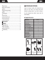
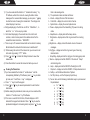
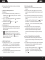
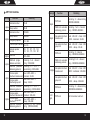
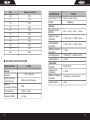
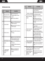
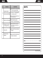
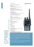
INSTRUCTION MANUAL
PT6808
TRUNKING MOBILE TRANSCEIVER
INSTRUCTION MANUAL
PT6808
TRUNKING MOBILE TRANSCEIVER
We are very grateful for your purchasing
brand
transceivers produced by Kirisun Communications Inc.
We believe
transceiver, which always incorporates the latest technology, can bring great convenience
to your life and work; we also believe that the quality and
function of
transceiver can meet your demands for
reliable communication.
NOTICE TO THE USER:
State laws prohibit radio communication without permission in government districts.
Illegal operation is punishable by fine and/or imprisonment.
Refer service to the well-trained professional technicians only.
SAFETY
It is important that the user is aware of and under-stands
hazards common to the operation of any transceivers.
WARNING!
Turn off your transceiver prior to entering any area with
a potentially explosive atmosphere (where the air contains
gas, dust and smog, etc.), such as while taking on fuel, or
while parking at a gasoline service station.
PRECAUTIONS IN USE
Please comply with the following attentions to avoid fire,
bodily injury and damage to the transceiver.
The transceiver is recommended to transmit for 1 minute
and receive for 4 minutes. Long time transmitting or
continuous working in high power mode will make the rear
side of the transceiver generate heat.
Please don't disassemble or assemble the transceiver
under any circumstances.
Please don't expose the transceiver to direct sunlight for
a long time; don't place the transceiver near any heating
devices, either.
Please don't put the transceiver in extremely dusty,
moist or dabbling places; don't place it on unstable surfaces,
either.
If the transceiver emits smoke or strange odors, turn it
off and remove the battery from the transceiver and promptly
contact your local authorized KIRISUN dealer.
CONTENTS
UNPACKING AND CHECKING……………………………………1
Supplied Accessories…………………………………………………1
PREPARATION………………………………………………………2
Connection of Power Cable…………………………………………2
Radio Installing………………………………………………………2
GETTING ACQUAINTED…………………………………………3
Radio Overview………………………………………………………3
Display………………………………………………………………3
TRUNKING MODE…………………………………………………5
Power ON/OFF………………………………………………………5
Viewing………………………………………………………………5
Viewing the Built-in Status Message………………………………5
Viewing the Received Status Message……………………………6
Viewing the Received Data Message……………………………7
Viewing the Missed Call……………………………………………7
Viewing the Parameters……………………………………………8
Viewing the Built-In Contact List……………………………………11
Radio Calls…………………………………………………………11
Making a Voice Call ( through Keypad Mainly )…………………11
Receiving a Voice Call………………………………………………12
Cancel a Call…………………………………………………………13
Redialing……………………………………………………………13
5 Digit Dialing………………………………………………………13
Queue Incoming Call………………………………………………14
Cancel“Queue Incoming Call”…………………………………14
Call Diversions……………………………………………………14
Diverting Your Own Call……………………………………………14
Diverting Third Party Call…………………………………………15
Cancel Diverting……………………………………………………16
Special Calls………………………………………………………17
Status Call…………………………………………………………… 17
Short Data Call………………………………………………………18
Emergency Call……………………………………………………19
Priority Call…………………………………………………………20
Conference Call……………………………………………………20
Broadcast Call………………………………………………………20
Include Cal…………………………………………………………20
ALLI System Call……………………………………………………21
PABX Call……………………………………………………………21
PSTN Call……………………………………………………………21
NPD Transfer………………………………………………………22
Network Operator Service Call……………………………………22
Don't Disturb…………………………………………………………22
Cancel “ Don't Disturb” …………………………………………23
Special features……………………………………………………23
Remote Kill & Reactivate…………………………………………23
Dynamic Group………………………………………………………23
Keypad Operations………………………………………………24
Fast Searching in Contact List……………………………………24
Manually Select Control Channel…………………………………24
Manually Select System Code to Join the Network……………25
Manually Switch Personal Ids… … … … … … … … … … … 25
Keypad Lock & Rotary Encoder Lock……………… ……………26
Enter the Open Channels…………………………………………26
Enter Conventional Mode…………………………………………27
Return to Trunking Mode from Conventional Mode……………27
CONVENTIONAL MODE…………………………………………28
Conventional channels……………………………………………28
Channel Scan………………………………………………………28
Scan Pause…………………………………………………………29
Revert Channel………………………………………………………29
Busy Channel Lock (BCL)…………………………………………29
Monitor………………………………………………………………29
Signal's Sending and Ending………………………………………30
DTMF…………………………………………………………………30
CTCSS & DCS………………………………………………………30
Time-Out Timer………………………………………………………30
Time-Out Timer Pre-alert……………………………………………31
Time-Out Timer Re-key……………………………………………31
Time-Out Timer Reset………………………………………………31
DATA SECURITY……………………………………………………31
APPENDIX……………………………………………… …………32
Special Dial Code……………………………………………………32
MPT 1343 Dial Mode………………………………………………34
Technical Specifications……………………………………………36
Troubleshooting ……………………………………………………38
UNPACKING AND CHECKING
Unpack the transceiver carefully. We recommend that you
identify the items listed in the following table before
discarding the packing material. If any items are missing or
have been damaged during shipment, please contact the
dealer immediately.
Supplied Accessories
Accessories
Fixed bracket
Power Cable
Hand Microphone
Microphone Hanger
M4*13 Self-tapping Screw
M4*16 Self-tapping Screw
M5*16 Self-tapping Screw
Spring gasket
Normal gasket
Instruction Manual
Warranty Card
Quantity
1
1
1
1
4
2
4
4
4
1
1
Microphone Hanger
Power Cable
Fixed bracket
Hand Microphone
M4*13 Self-tapping
Screw
M5*16 / M4*16
Self-tapping Screw
1
Preparation
Connection of Power Cable
* First of all, please check whether there is a hole for the
power cable on the insulating board. If no, please bore the
board with the suitable drill bit and fix a rubber grommet on it.
* Afterwards, please have the cable pass through the
insulating board and lead from the car into the car engine.
Connect the red conductor to the positive terminal of the
accumulator and the black conductor to the negative terminal.
* At last, ring the remained conductor and fix it.
Note: Please maintain the sufficient relaxation of the
power cable to make it convenient to dismantle the radio in
the state of power connection.
Radio Installing
Warning: For passengers' safety, please fix the radio firmly
on the fixed bracket so that the radio will not be loosened in
case of collision.
* The fixed bracket is taken as an example. Draw the position
and drill a hole on the instrument panel first, and then install the
fixed bracket with 4 M5*16 self-tapping screws. (Note: please fix
the radio at the position convenient for operation and control,
and leave an enough space for fixation and connection of the
cable.)
* Slide the radio into the fixed bracket and fix it with 4 M4*10
combination screws (plus plain washer and spring washer).
(Different combinations of fixing holes are selectable to adjust
the radio to the proper height and visual angle.)
2
* Connect the antenna and the power cable to the radio.
* Install the microphone hanger at the position easy to use, with
2 M4*16 self-tapping screws. (The microphone and its cable sho-uld be fixed at the position not affecting safe driving.)
*Connect the microphone to the microphone jack on the front
panel of the radio and put it on the hanger.
Note: When replacing the protective tube for the power cable,
please use the one of the same specification without fail. It is
not allowed to change it into the tube of higher capacity.
GETTING ACQUAINTED
Radio Overview
Display
1) Displays call addresses, the call duration timer, data messages,
and the current operating status of the transceiver. (TRUNKING
mode only.)
2) Displays the channel numbers and the current operating status of
the transceiver. (CONVENTIONAL mode only.)
3) Status indicator symbols are explained in the table below:
3
ICON
DESCRIPTION
Shows the strength of receiving signals.
SVC
Appears when a control channel is found. Flashes while
the transceiver is hunting for a control channel.
(TRUNKING mode only.)
MON
Appears while you are monitoring a channel by pressing
the Monitor button. (CONVENTIONAL mode only.)
SCN
Appears while you are scanning. (CONVENTIONAL
mode only.)
Lo
Appears when the transmitting power is in the Low mode.
P
Appears when you are in home system, and disappeared
when in rovingroaming. (TRUNKING mode only.)
Appears when there is new data received,including voice
message, digital data message and missed calls.
(TRUNKING mode only.)
Appears when you are in roaming. (TRUNKING mode
only.)
Appears when keypad lock or rotary encoder lock
is active.
Indicates that the encoder switch is locked.
Ring alert is active when the setting is not All Mute.
(TRUNKING mode only.)
Shows the current battery level, and flashes when
the battery power appears low.
4
TRUNKING MODE
Power ON/OFF
1) Press the red POWER button for a long time (at least 1.5
seconds) to switch on the transceiver. All characters on display
flash and the power-on text message appears. The transceiver
will automatically begin hunting for a control channel. While the
transceiver is hunting, the" SVC" indicator flashes and Hunting
displays.
Before the searching,
a. Power-on music should be accompanied with the power-on
message if the Mute is not set. Refer the setting and canceling of
power-on message to your local dealer.
b. “PASSWORD”should be displayed before the power-on
message if the password had been set by PC software. Input the
password and end with “#”to confirm the password. The
power-on message would show if the password is correct. Refer
the setting and canceling of password to your local dealer.
c. “Killed”would be displayed after the power-on message show
when the transceiver was remote killed, and the transceiver is not
allowed for use. Please contact the system administrator for help.
d. “UNPROGRAM” should be displayed before the power-on text
if the network parameters are not programmed. Please contact
your local dealer.
2) Turn the On-Off/Volume control knob counterclockwise to switch
the transceiver power off.
Viewing
Viewing the Built-in Status Message
1) If you have selected the function of “viewing the built-in status
5
message”by PC software, you can press“ ”key once to
enter the mode of viewing the status messages.
a. “Statusxx”will be displayed on LCD.
b. The content of built-in status messages can only been programmed
by PC software. Please contact your local dealer for detail
information.
c. There are up to 32 status messages, and Chinese and English
characters can be stored in each message.
2) Press “ ”and “ ”or rotate the Rotary Encoder to view the
status messages. Press“ ”or rotate clockwise to increase the
status code, and “ ”or counterclockwise to decrease it.
3) Press Clear button to exit.
Viewing the Received Status Message
1) If you have selected the function of “data message stack”by PC
software, while in the mode of viewing the Built-in status
message, you can press“ ”key once again to enter the mode
of viewing the received messages. The message type and
content display in two lines.
a. Message type displaying in the first line on LCD is“RecStatus
xx”, in which the“xx” is the enquiry number.
b. Message content displaying in the second line consists of“
Sending unit ”and“ Content”.
c. There are two pages of content for each received status message,
one is for “Sending unit” and the other is for“ Content”. The
“Sending unit” displays the sender's ID and the “Content”
displays built-in status message. Press “ ” key to switch the
displayed page between“Sending unit” and “Content”.
d. There are up to 30 received status messages can be stored in
memory. But all messages will be lost when the transceiver is
6
switched off.
2) Press “ ”and“ ”or rotate the Rotary Encoder to view the
received status messages.
3) Press Clear button to erase the received status message while
you view it.
Viewing the Received Data Message
1) If you have selected the function of “data message stack”by
PC software, while in the mode of viewing the received status
message, you can press “ ”key to enter the mode of viewing
the received data messages. The message type and content
display in two lines.
a. Message type displaying in the first line on LCD is“DataMsgxx”,
in which the “xx” is the enquiry number.
b. Message content displaying in the second line consists of“
Sending unit”and“Content”。
c. There are two pages of content for each received data message,
one is for“Sending unit”and the other is for “Content”.The“
Sending unit” displays the sender's ID and the “Content”
displays built-in data message. Press “ ” key to switch the
displayed page between“Sending unit” and “Content”.
d. There are up to 5 received data messages can be stored in
memory. But all messages will be lost when the transceiver is
switched-off.
2) Press“ ”and“ ”or rotate the Rotary Encoder to view the
received data messages.
3) Press Clear button to erase the received data message while you
view it.
Viewing the Missed Call
7
1) If you have selected the function of“ missed call memory” by
PC software, while in the mode of viewing the built-in status
message or the received data message, you can press “ ”key
to enter the mode of viewing the missed calls. The call type and
content display in two lines.
a. Call type displaying in the first line on LCD is “MissCallxx”, in
which the “xx” is the enquiry number.
b. Call content displaying in the second line is the caller's unit
number, or caller's name preset in the address book. For the
unidentified caller it will show “UNKOWN”.
c. There are up to 10 received missed calls can be stored in memory.
But all data will be lost when the transceiver is switched-off.
2) While viewing the content of the missed call, you can send a call
to its caller by pressing“PTT”button.
3) Press“ ”and“ ”or rotate the Rotary Encoder to view other
missed calls.
4) Press Clear button to erase the missed call while you view it.
Viewing the Parameters
1) If you have selected the function of“enable menu”and the
corresponding facilities by PC software, press“ ”key in standby mode, and“Lock Press * key”is displayed.
a. Press“*”key to lock the keypad .
b. Press“ ”or“ ”key to view/set parameters for each function
listed below.
2) Before viewing the parameters, make sure you have select-ed the
function of“function menu”by PC software.
3) If the menu is used for the first time, ID code displays on LCD
instead of the keypad lock indicator. Press“ ”key to view the
parameters displayed in increasing order; and press“ ”to view
8
them in decreasing order.
The parameter codes are listed as follows:
Idcode -- display ID code of the transceiver.
ControlCH -- display the current control channel.
SystemCode -- display the current system code.
Power-- display and set the transmitting TX power in trunking
mode.
e. BeepVolume -- display and set the beep volume.
f. RingVolume -- display and set the ring volume of the incoming
calls.
g. MsgVolume -- display and set the alarm volume of received
messages.
h. RingType -- display and set the ring music type of incoming
individual calls.
i. GroupRing-- display and set the ring type of incoming group calls.
j. Silence -- display and set the ON/OFF of the mute of “Beep”
and incoming calls.
k. Lamp -- display and set the ON/OFF of backlight on LCD.
l. Cmp Hunt -- display and set the ON/OFF of Comprehensive Hunt.
m. SelSys -- set the Manual Selection of System.
n. Set Tmp Group -- set the Temporary Input Group.
5) You can also use the following combination keys to quick view/set
the parameters:
a. 0+“ ”key
b. 1+“ ”key
c. 2+“ ”key
d. 3+“ ”key
e. 4+“ ”key
f.
5+“ ”key
g. 6+“ ”key
h. 7+“ ”key
4)
a.
b.
c.
d.
9
6)
7)
a.
b.
8)
a.
b.
c.
d.
10
i.
8+“ ”key
j.
9+“ ”key
By PC software you can define the function of above series
of combination keys as displaying/setting: ID code of the
transceiver, current control channel, current system code,
TX power, ON/OFF of back light on LCD, ON/OFFof
Comprehensive Hunt, switch between conventional mode
and trunking mode, rotary encoder lock.
All settings of above facilities, except“SetTmpGroup” and “
SelSys”, can be adjusted only by Rotary Encoder. Press Clear
button to return to standby mode while adjusting.
When“SelSys”displays, press “ ”to select the system
manually. “SelSys xxxx xxxxxxxxxxxx” will be displayed. (The
exact display lies with the setting of system.)
Press “#” or PTT to select the system code manually. If the
function of selecting system code manually hasn't been activated
or this system code is prohibited to select manually, it will return to
trunking mode when press “#” key or PTT button.
Press“ ”key to return to the menu.
When “SetTmpGroup” displays, press“ ”key to set
Temporary Group. “SetTmpgroup x xxx”will be displayed on
LCD. (The exact display lies with the setting of system.)
Input the group call code of the Temporary Group through the
number keypad and end with“#” key. 3 temporary groups can
be stored in the transceiver.
Press Clear button to erase this group call code and then“Null”
displays on LCD. Press“#”key to confirm.
Press “ ”or “ ”key or rotate the Rotary Encoder to view the
other 2 groups.
Press“ ”key to return to trunking mode.
Viewing the Built-In Contact List
1) The built-in contact address can only be edited by PC software.
The setting categories are: group/individual call, hide group,
dialing number.
2) You can set 180 group/individual calls, 50 hide groups, and 20
groups of dialing numbers.
3) Rotate the Rotary Encoder to view the contacts in standby mode.
4) The ASCII name of a contact can also be displayed if it has been
set.
1)
2)
a.
b.
c.
3)
a.
Radio Calls
Making a Voice Call ( through Keypad Mainly )
Make sure you have activated by PC software the inter-prefix
individual call, inter-prefix group call, inter-fleet individual call and
inter-fleet group call, and have set the proper calling range limit.
Individual call ( for example, to call the number 201-2001-207):
Input the individual call number and then press the “#” key or
PTT button to transmit.
Individual call of the same prefix and fleet: Input individual call
number + # /PTT.
Dialing sequence: 2+0+7+#/PTTkey
Individual call of the same prefix but different fleet: Input fleet code
+individual call number + # / PTT button.
Dialing sequence: 2+0+0+1+2+0+7+# /PTT
Individual call of different prefix and fleet: Input prefix code + fleet
code + individual call number+# /PTT button.
Dialing sequence: 2+0+1+2+0+0+1+2+0+7+# /PTT
Group call (for example, to call the number 201-5000-909):
Group call of the same prefix and fleet: Input group call number +
11
# /PTT key.
Dialing sequence: 9+0+9+# /PTT
b. Group call of the same prefix but different fleet: Input fleet code+
group call number + # /PTT
Dialing sequence: 5+0+0+0+9+0+9+# /PTT
c. Group call of different prefix and fleet: Input prefix code + fleet
code + group call number +# /PTT
Dialing sequence: 2+0+1+ 5+0+0+0+9+0+9+# /PTT
Receiving a Voice Call
When there is a voice call received the caller's number and its
group number will be displayed on LCD.
1) When there is a call:
a. If the call is from an ordinary unit or unit other than following
types, LCD displays “Unit Call”.
b. If the call is of the same prefix and fleet, LCD displays“Unit
xxx”.
c. If the call is of the same prefix but different fleet, LCD displays “
xxxx-xxx”.
d. If the call is of different prefix and fleet, LCD displays “xxx-xxxxxxx”.
e. If the caller's address and name are stored in the address book,
the caller's name will be displayed instead of his number.
2) “ EMG Call” will be displayed for emergency Call.
3) “GROUP Call” will be displayed for group Call. When receiving a
group call, the caller's number and the group number being called
will be displayed dynamically.
4) “Bcast Call” will be displayed for broadcasting Call.
5) Press PTT button to answer the call. Press Clear button to end or
exit the call.
12
6) After the call, LCD displays “Call Ended”, and then the
transceiver returns to the Home address if you have preset it by
PC software, otherwise, resumes the caller's address displayed
before.
Cancel a Call
1) Press *+ # to end a call.
2) Press Clear button to cancel a call.
Redialing
1) 10 groups of dialed number can be stored in the transceiver.
2) Press Redial button to display on LCD the last effective dialed
number in Standby mode.
3) Press “ ”or “ ”key or rotate the Rotary Encoder to view
dialed numbers.
4) Press PTT or“#”key to call. Or press Clear button to erase the
number.
5 Digit Dialing
1) Make sure you have selected the MPT1343 dialing mode by PC
software and preset the 5 digit dialing abbreviatory codes.
2) By PC software you can set the call type, prefix, fleet number,
number range with the corresponding abbreviatory codes, the
range of which is 20~99.
3) For example in the setting of abbreviatory code 23NNN, the call
type is individual call; the number prefix is 237; the fleet number
is 2341; the code range is 256. When you call the party whose ID
number is 237-2341-214, you can only press 2+3+2+1+4+#/ PTT
button to call.
4) If make a group or individual call of a small fleet, you need to add
13
“0” before the group or individual call number.
Queue Incoming Call
1) Make sure “queue incoming call” function has been set by PC
software.
2) “Queue incoming calls”: The transceiver uses ACKB to respond
an incoming call and put it into the queque. In this mode the “
Don't Disturb” function is cancelled.
3) Dial in the sequence of*+4+8+# to activate “queue incoming
call”.
4) “Complete”or “SUCCESS” appears on the screen when the
setting completes. Warning tone sounds on the same time if it has
been set by PC software.
Cancel“Queue Incoming Call”
1) Dial in the sequence of #+4+8+# to cancel“queue incoming
calls”.
2) “Complete”or“SUCCESS”appears on the screen when the
setting completes. Warning tone sounds on the same time if it has
been set by PC software.
1)
2)
3)
a.
14
Call Diversions
Diverting Your Own Call
Incoming voice calls, status messages and data messages on
your own transceiver can be diverted to other transceivers.
Make sure“own call diversion”function has been set by PC
software.
While in standby mode, you can divert the call through the
following operations:
Dial in the sequence of *+4+1+* to divert all calls.
Dial in the sequence of *+4+1+1+*to divert voice calls only.
Dial in the sequence of *+4+1+2+* to divert data calls only.
Input the code of the transceiver, which will receive call diversion.
Press“# /PTT”button to send call diversion. “Self Diverting”
displays.
f. If the diverting succeeds, warning tone sounds and “Complete”
or “SUCCESS”appears on the screen.
g. If the diverting fails, warning tone sounds and “Call Failed”or “
FAIL”appears on the screen.
b.
c.
d.
e.
Diverting Third Party Call
1) “Third party diversion” function cancels own call diversion to the
other transceiver, and diverts all incoming voice calls, status
messages and data messages from your own transceiver to the
third transceiver.
2) Make sure that “third party diversion” has been set by PC
software.
3) While in standby mode, you can divert the call through the
following operations:
a. Dial in the sequence of *+4+4+*to divert all calls.
b. Dial in the sequence of *+4+4+1+* to diverts voice calls only.
c. Dial in the sequence of *+4+4+2+* to divert data calls only.
d. Input the code of the transceiver, which has already been diverted.
Then input * and the code of the transceiver which will be
receive the call diversion.
e. Press “#/PTT ”button to send call diversion. “Third Diverting”
appears on the screen.
f. If the diverting succeeds, warning tone sounds (if it has been set
by PC software) and “Complete”or“SUCCESS”appears on
the screen.
15
g. If the diverting fails, warning tone sounds and “Call Failed”or“
FAIL”appears on the screen.
Cancel Diversion
1) Call diversion can be canceled on the transceiver.
2) To cancel call diversion on your own transceiver, follow the
operations below:
a. Dial in the sequence of # +4+1+# to cancel all the call diversions.
b. Dial in the sequence of # +4+1+1+# to cancel voice call diversions
only.
c. Dial in the sequence of # +4+1+2+# to cancel data call diversions
only.
d. “Canceling Divert” displays on the screen.
e. When the setting is completed, warning tone sounds (if it has been
set by PC software) and“Complete”or “SUCCESS”appears
on the screen.
3) To cancel call diversion on other transceiver, follow the operations
below:
a. Dial in the sequence of # +4+4 to cancel all call diversions.
b. Dial in the sequence of # +4+4+1 to cancel voice call diversions
only.
c. Dial in the sequence of # +4+4+2 to cancel data call diversions
only.
d. Input * and the code of the transceiver on which call diversion will
be diverted be canceled.
e. When the setting is completed, warning tone sounds (if it has been
set by PC software) and“Complete”or“SUCCESS” appears
on the screen.
4) Cancel all calls diverted to your own transceiver:
a. Dial in the sequence of # +4+5+# to cancel all call diversions.
16
b. Dial in the sequence of # +4+5+1+# to cancel voice call diversions
only.
c. Dial in the sequence of # +4+5+2+# to cancel data call diversions
only.
d. When the setting is completed, warning tone sounds (if it has
been set by PC software) and“Complete”or “SUCCESS”
appears on the screen.
Special Calls
Status Call
1) A status message code is a one used for transmitting sending
preset messages.
2) Make sure“status message call”function has been set by PC
software.
3) Send a status message by dialing the keypad. (It's used as an
example in the following description that 201-2001-204
transmitting sends the 12th message to 201-2001-205.)
a. Dial in the sequence of *+0+1+2+*+2+0+5 ( If the prefix are
different, you need to dial *012*+prefix + fleet + individual call
number.)
b. Press“#”or PTT button to send the status message. “Sending
status”will display.
c. If the transmitting succeeds, warning tone sounds and“
Complete”or “SUCCESS”appears on the screen.
d. If the transmitting fails, warning tone sounds and “Call failed”,
“FAIL”, “Unavailable” or “NO ANS”appears on the
screen. If the input call address is invalid number, “Null
number” appears.
4) Send a status message by selecting in the menu.
17
a. Rotate the Rotary Encoder to select the contact or input the call
address.
b. Press“ ”key to enter the mode of viewing the built-in status
messages, and press “ ”or “ ”key or rotate the Rotary
Encoder to select the corresponding status message.
c. Press PTT button to send the status message. The display is “
Sending status”
d. If the transmitting succeeds, warning tone sounds (if it has been
set by PC software) and“Complete”or “SUCCESS”appears
on the screen.
e. If the transmitting fails, warning tone sounds (if it has been set by
PC software) and “Call failed”, “FAIL”, “Unavailable”or“
NO ANS”appears on the screen. If the input call address is
invalid number,“Null number” appears.
5) Receive a status message:
a. When receiving a status message is received, warning tone
sounds (if it has been set by PC software) and the“ ”indicator
flashes on the screen.
b. Press“ ”key twice to view the received status message.
Short Data Call
1) Make sure that “short data call”function has been set by PC
software.
2) A short data message sent on control channel is of 184bit at most
(MPT1327) or of 100 characters at most (MPT1343).
3) The formats of short data are MPT1327, MPT1343 BCD,
MPT1343 ASCII, which are set by PC software.
4) For example, dial in the sequence of *+2+*+123456+* +245,
in which 245 is the number being called and 123456 is the data
being transmitted.
18
5) Press PTT or # key to send the short data.
6) If the transmitting succeeds, warning tone sounds (if it has been
set by PC software) and“Complete”or “SUCCESS”appears
on the screen.
7) If the transmitting fails, warning tone sounds (if it has been set by
PC software) and “Call failed”, “FAIL”, “Unavailable” or
“NO ANS”appears on the screen. If the input call address is
invalid number, “Null number”appears.
8) When a short data is received, warning tone sounds (if it has been
set by PC software) and the “ ”indicator flashes on the
screen. Press“ ”key twice to view the received Data
message.
Emergency Call
1) Emergency Calls have the highest call priority. Usually, they are
prior to any other types of calls.
2) Make sure that “emergency call”function, “emergency call
address” and “key hold time” have been set by PC software.
3) Send an emergency call by pressing emergency button. Make
sure the pressing time is longer than or the same as “key hold
time”。When it reaches the touch off time, the transceiver will
send emergency call to the preset “Emergency Call Address”
automatically.
4) Send an emergency call by dialing keypad:
a. Dial in the sequence of *+9+*+2+0+5. (it is used as an example
that 201-2001-204 calls 201-2001-205; if prefix and fleet are
different, you need to dial *9*+ prefix + fleet + individual call
number. )
b. Press “#” key or PTT button to call. “EMG Calling”or “
HELPING”appears on the screen.
19
Priority Call
1) Priority Call allows you to have the priority over other users when
requesting a call.
2) Make sure that“priority call”function has been set by PC
software.
3) Dial in the sequence of *+8+*+2+0+5 to initiate a priority call. (It
is used as an example that 201-2001-204 calls 201-2001-205; if
prefix and fleet number are different, you need to dial *8*+
prefix + fleet + individual call number.) *8 is the code for priority
call and 205 is the number that you calls.
4) Press # or PTT button to call. “Calling”appears on the screen.
Conference Call
1) Conference Call allows you to call the preset talk-group.
2) Make sure that“conference call”function has been set by PC
software.
3) Dial in the sequence of *+1+*+ group address + # /PTT to
initiate a conference call.
1)
2)
3)
4)
Broadcast Call
Broadcast Call allows you to call a group of transceivers. (During a
broadcast call, only the caller can speak.)
Make sure that“broadcast call”function has been set by PC
software.
Dial in the sequence of *+1+1+*+ group address.
Press # /PTT button to call.“Calling” appears on the screen.
Include Call
1) Include Call allows the third party to join the talk in the cou-rse of
talking.
20
2) Make sure that“include call”function has been set by PC
software.
3) During the course of talking, dial the third party's unit num-ber
directly and press “#”or PTT button to call.
4) When calling, the display is “Include call”. Press Clear button
to cancel the include call, and “IncludeCancel”displays on the
screen.
ALLI System Call
1) ALLI system call allows transceiver to call all the transce-ivers
registered on the network.
2) Make sure that“ALLI system call” function has been set by PC
software.
3) Press *+1+9+8+1+# to initiate Priority voice system-wide-call.
4) Press *+1+9+8+2+# to initiate Emergency voice system-widecall.
5) Press *+1+9+8+7+# to initiate Standard voice system-wide-call.
PABX Call
Make sure that“PABX call” function has been set by PC
software.
There are 4~9-digit dialing modes for PABX call.
1) 4 digit dialing mode: Input 4 digit number to call directly.
2) 5 ~9-digit dialing mode: Extension code composed of digits 0, 7
or 8 should be added before the PABX extension number to dial.
3) Press “#” key or PTT button to call.
PSTN Call
1) Make sure that“PSTN call” function has been set by PC
software.
21
2)
3)
4)
5)
There are 8 ~ 30-digit dial modes for PSTN call.
Number 0 should be added before PSTN number.
Press “#”key or PTT button to call.
If “DTMF dialing while PSTN call” function has been set by PC
software, and “forbid data keypad” function is not activated,
you can make DTMF call by inputting the number while holding
down PTT button.
NPD Transfer
1) Make sure that“Non-prescribed data transfer”function has been
set by PC software.
2) Press *+1+9+8+3+# to initiate Emergency NP data system-widecall.
3) Press *+1+9+8+4+# to initiate Priority NP data system-wide-call.
Network Operator Service Call
1) If your transceiver requires network service, it needs the
cooperation of the relevant base station.
2) Before calling the dispatch station, you need make sure that“
Network Operator Service Call”function has been set.
3) Input the number of the dispatch station (see Appendix MPT1343
Dial Mode table) + “#” /PTT to call the dispatch station.
Don't Disturb
1) This function allows transceiver to refuse calls from other
transceivers under special circumstances.
2) Make sure that“Don't Disturb”has been set by PC software.
3) Dial in the sequence of *+4+9+# to refuse all calls.
4) Dial in the sequence of *+4+9+1+# to refuse voice calls.
5) Dial in the sequence of*+4+9+2+# to refuse data calls.
22
6) When the setting is completed, warning tone sounds (if it has
been set by PC software) and“Complete”or“SUCCESS”
appears on the screen.
Cancel “Don't Disturb”
1) Dial in the sequence of # +4+9+# to cancel all“Don't Disturb”.
2) Dial in the sequence of # +4+9+1+# to cancel voice“Don't
Disturb”.
3) Dial in the sequence of # +4+9+2+# to cancel data“Don't
Disturb”.
4) When the setting is completed, warning tone sounds (if it has
been set by PC software) and “Complete”or “SUCCESS”
appears on the screen.
Special Features
Remote Kill & Reactivate
1) The base station can give remote killing order to the lost or stolen
transceiver to prohibit its operating. And the base station can also
give reactivating order to resume its normal working.
2) After receiving remote killing instruction, “Killed”displays.
3) If switch on the transceiver again,“Killed”still displays. Only
after receiving the reactivating order from the base station, the
remote killed transceiver can return to normal operation.
Dynamic Group
1) Dynamic grouping function allows base station to group units as a
new team by remote control.
2) The address (number) of this dynamic group is sent to your
transceiver by the system, and therefore you may become a
23
member of the dynamic group, able to receive calls and
(depending on how your transceiver is programmed) send calls to
that group.
3) After receiving the order of dynamic grouping, the transcei-ver
displays“Dynamic Team”and the corresponding prefix, fleet
and group number of the dynamic group.
1)
2)
3)
4)
Keypad Operations
Fast Searching in Contact List
Make sure“fast searching in contact list”function has been
selected by PC software.
Input the number you are searching and press “ ”key to fast
switch to this number. The fast searching is only available for
individual and group numbers.
If the input number is invalid, it will return to the previous call
address automatically, or return to home address if it has been
preset.
If the input number is group number and not stored in the contact
list, the transceiver will store it in the first temporary group and
switch the call address to this temporary group.
Manually Select Control Channel
1) In trunking mode you can select the network by inputting the
control channel code.
2) Make sure that“select control channel manually”function has
been set by PC software.
3) In trunking mode, input“#5”+ control channel number. Then you
can start “select control channel manually”. The range of the
preset control channel code is 1~1023.
4) If you haven't preset control channel for the input number, the
24
transceiver returns to trunking mode immediately.
5) When manually searching control channel, “Search ch xxxx”
(xxxx is the corresponding channel number ) is displayed on the
screen.
6) If the searching fails, “Search Fail Return?”appears on the
display. Then press any key to return to trunking mode.
Manually Select System Code to Join the Network
1) In trunking mode you can search the base station by selecting
system code manually.
2) Make sure that“select system code manually”functio has been
set by PC software. And the manually selecting has been set in
the “Multiple System Select” option.
3) In trunking mode, Input “#7”+ preset system code +“#” key
or PTT button, or input “1” + preset system code + “ ”key,
and then you can start “Select System Code Manually”. The
range of system code is 000~160.
4) If you have not preset system code for the input number or the
system code isn't set as being selected manually, the transceiver
returns to trunking mode immediately.
5) When manually select system code,“Search Sys xxxx” (
xxxx is the corresponding system code ) is displayed on the
screen.
6) If the searching fails,“Search Fail Return?”appears on the
display. Then press any key to return to trunking mode.
Manually Switch Personal IDs
a) Maximum 6 sets of net/personal datas can be stored in the radio;
b) You can switch among different nets/personal IDs by pressing
"#8+N+#" keys (N can be 1~6);
25
c) After successfully switching the datas, the radio will automatically
turn off and turn on again.
Keypad Lock & Rotary Encoder Lock
1) Keypad Lock
a. If you have selected the function of selecting“Enable menu” by
PC software, press“ ”key in stand-by mode, and “Lock Press
* key”is displayed.
b. Press“*”key to lock the keypad and the“ ”icon appears on
the screen when it succeeds.
c. To release the lock, press“ ”key + “*”,“ ”icon
disappears when it succeeds.
2) Rotary Encoder Lock
a. You can set the way of activating the rotary encoder lock by PC
software. By the way you preset you can enable or release the
rotary encoder lock.
b. “ ”icon appears on the screen when the lock is active;
“ ”icon disappears when the lock is inactive. For exam-ple,
you can set the function of pressing “1+ ”as the switch of the
rotary encoder lock, and then press “1+ ”key you can
activate or inactivate the lock.
Enter the Open Channels
1) In trunking mode, dial “101~110”+ “#”key or PTT button to
enter the channels “1~10”in conventional mode separately.
2) You can also set the emergency call number as anyone of the “
101~110”. When you press the emergency button you can enter
the corresponding channel.
3) If no conventional channel is preset or the conventional function is
not activated, the display is“Null number”.
26
Enter Conventional Mode
1) Make sure you have set conventional mode and conventi-onal
channels.
2) While in trunking mode, press“ ”key to enter conventi-onal
mode if you have select entering conventional mode by means of
default.
3) If you select entering conventional mode by means of compound
keys, then you can enter conventional mode in the way set in PC
software.
For example, when the combination keys of “9+
” are set by
PC software as “ switch between conventional mode and
trunking mode”, you can enter conventional mode by pressing
“9” and “ ”.
4) The transceiver can be set to enter conventional channel
automatically when missing the control channel. When the
transceiver is beyond the network coverage, it switches to
conventional mode automatically according to the preset delay
time.
Return to Trunking Mode from Conventional Mode
1) Press Clear button to return to trunking mode in conventional
mode if you have select entering conventional mode by means of
default.
2) If you select entering conventional mode by means of combination
keys, then you can return to trunking mode from conventional
mode in the way set in PC software.
For example, when the combination keys of “9+ ” are set by
PC software as “ switch between conventional mode and
trunking mode”, you can return to trunking mode by pressing “
9” and “ ”.
27
3) The transceiver can be set by PC software to search control
channel automatically in conventional mode. In conventional
mode, if no signal is received, the transceiver will switch to
trunking mode automatically according to the preset delay time.
While in mode-switching operation, there is a BEEP warning tone.
CONVENTIONAL MODE
Conventional Channels
1) Press PTT to transmit and release to receive.
2) Through PC programming the parameters of conventional mode
can be set, such as channel name, RX/TX frequency and BCL,
etc.
3) This transceiver can set 32 conventional channels at most.
4) Select channel by rotate the Rotary Encoder.
5) When transmitting, time display prompts TOT.
6) “Lo”indicates low power transmission.
7) Press“Monitor”button to monitor.
Channel Scan
1) 32 channels can be set through PC programming, and the
parameters on each channel can be set, such as CTCSS/ DCS
encoding and decoding, broad band/narrow band, BCL, high
power/low power, voice compander, channel name, etc.
2) Press “ ” to begin scanning. When scanning, LCD displays “
Scanning”.
3) Scan the channel added in scan sequence list only ( and scan just
when there are 2 or more than 2 channels added in scan list.)
Those channels are indicated by“↘”.
4) To add channels to scan sequence, select the channel you need to
add and press “ ” key. “↘”displays indicating the
28
accomplishment of adding.
5) To delete channels from scan sequence, select the channel you
need to delete and press “ ” key. “↘”disappears indicating
the accomplishment of deleting.
Scan Pause
1) If the signal is detected while in channel scanning, the scanning
will pause and the information of the paused channel will be
displayed.
2) Press PTT button and speak to microphone to call. (turn on This
action activates TOT if this function has been preset)
3) If the PTT button is released and no signal is receiveed,
transceiver can continue the scanning after the preset delay time.
Revert Channel
1) If you press PTT button while in channel scanning, the transceiver
stops scanning on revert channel and transmits on this channel.
2) By PC software, you can set the revert channel to the channel “
last called”, “last used”or “selected”.
Busy Channel Lock (BCL)
1) This function can prevent other radios on the same channel from
being interfered.
2) When the channel is occupied, transceiver will make warning tone
and prohibit the transmitting if you press PTT button; if you
release PTT button, the warning tone stops and transceiver
returns to receiving mode.
Monitor
1) Rotate the Rotary Encoder and select the channel you need.
29
2) Press“Redial/Monitor”button to monitor all activities of the
channel. “MON” symbol appears on the screen.
3) Press“Redial/Monitor”button again to cancel monitor function
and resume the original state.
heard.
3) To stop the warning tone, release the PTT button. You can press
PTT again to resume transmitting.
Signal's Sending And Ending
1) Rotate the Rotary Encoder to select the channel you need.
2) Press PTT button to transmit and release to receive.
Time-Out Timer Pre-Alert
1) This function is used to notify you a certain time before the preset
time-out time reaches.
2) The time can be set only by PC software.
DTMF
1) Make sure you have selected the DTMF function by PC software
and“Forbid Data Keypad” function is not activated.
2) While pressing PTT button, input the number. Then you can hear
DTMF sound from speaker.
Time-Out Timer Re-key
1) This function is used to set the “penalty” time in which the radio
cannot be re-keyed for transmitting after the time-out timer setting
is exceeded.
2) During this period, any operation on PTT brings warning tone.
CTCSS/DCS
1) Dealer might have set CTCSS/DCS signal on transceiver's
channel. CTCSS audio frequency or DCS code is subaudible
frequency tone/, or DCS code is code. Calls from other irrelevant
radios on the same channel will be ignored.
2) When a channel is set with CTCSS/DCS code, squelch function
can only be turned on when signal of matchable tone/code is
received. Squelch function cannot be turned on when the other
party uses different audio frequency or code to call.
Time-Out Timer Reset
1) This function is used to set the minimum“wait” time allowed
between transmissions that reset the Time-out Timer.
2) When“TOT reset time” is set, it causes the TOT continue even
after PTT is released unless TOT reset timer has expired
Time-Out Timer
1) Time-out timer is to prevent any single person from using a
channel to transmit for an extended period of time.
2) If you continuously transmit longer than the time limit preset by the
dealer, the radio will stop transmitting and a warning tone will be
30
DATA SECURITY
1) By PC software the radio password can be set to prevent others
from using without authorization.
2) By PC software the “Read/Write Password” can be set to
prevent others from reading or writing the data on the radio.
3) By PC software the passwords of “ Program Execution”, “
Network File” and “Personal File” can be set to prevent
others from editing or programming the PC software and the files.
31
APPENDIX
Function
Dial string
Function
Special Dial Code
Dial string
Standard voice system calls
*1987#
Diverting your own call
*41*, *411*, *412*
Third party diversion
*44*, *441*, *442*
Cancel a call
Send status message
Send short data message
*#
*0nn
*2*
Queue incoming calls
*48#
Conference calls
Broadcast calls
Priority voice calls
Emergency voice calls
*1*
Don't disturb (voice, data or both )
*49#, *491#, *492#
*11*
Priority calls
*8*
Emergency calls
*9*
End dial string
#
Cancel own call diversion
#41#, #411#, #412#
Cancel third party diversion
#44, #441 #442
Totally cancelled by the receiving party
#45#, #451#, #452#
Cancel “Queue incoming Calls”
#48#
Cancel “Don't Disturb”
#49#, #491#, #492#
Manually switch to control channel
#5
Priority NP data system calls
Emergency NP data system calls
*1981#
*1982#
*1983#
*1984#
Manually select system code to join the
#7
network
32
33
MPT1343 Dial Mode
Dial digit
Dial digit
Function
Individual number
2 digits Group number
Dial string
PSTN call
20~89
8 digits
200~899
Group number
900~998
3 digits Emergency operator
9 digits
112,999
Enter the open channels 101~110
100,111,121,131,141,
151,161,171,181,191
4 digits PABX call
1000~8999
PABX call (single
5 digits address word calls)
PABX call (extended
addressing protocol)
Common prefix
Inter-fleet individual call
6 digits
Common prefix
Inter-fleet group call
First string(3~6)+ Second
string(1000~8999)
First string(0,7,or 8)+
Second string(0000~9999)
10 digits
PABX call(extended
addressing protocol)
34
First string(0)+ Second string
(0000000~9999999)
Inter-prefix Inter-fleet
individual call
Prefix(200~327)+Fleet(2001
~6050)+Individual(20~89)
Inter-prefix Inter-fleet
group call
Prefix(200~327)+Fleet(2001
~6050)+ Group(90~99)
PSTN call
First string(0)+Second
string(00000000~99999999)
PABX call(extended First string (7 or 8)+ Second
addressing protocol) string(00000000~99999999)
Fleet(2001~6050)+
Individual(20~89)
Fleet(2001~6050)+
Group(90~99)
First string(0,7,or 8)+
Second string(00000~99999)
Fleet(2001~6050)+
Common prefix
Inter-fleet individual call Individual(200~899)
Fleet(2001~6050)+
7 digits Common prefix
Inter-fleet group call
Group(900~998)
First String(0,
7,or 8)+Second
PABX call(extended
addressing protocol)
String (000000~999999)
Dial string
PABX call(extended First string(7 or 8)+ Second
addressing protocol) string(0000000~9999999)
90~99
Individual number
Network operator
services
Function
Inter-prefix Inter-fleet
individual call
Prefix(200~327)+ Fleet(2001
~6050)+Individual(200~899)
Inter-prefix Inter-fleet
group call
Prefix(200~327)+Fleet(2001
PSTN call
11~30
digits
PSTN call
~6050)+ Group(900~998)
First string(0)+ Second string
(000000000~999999999)
The first number must be 0.
35
Dispatch station ID
Dial
100
8170
111
8171
121
8172
131
8173
141
8174
151
8175
161
8176
171
8177
181
8178
191
8179
999
8180
TECHNICAL SPECIFICATIONS:
PT6808
SPECIFICATIONS
General
(350 ~ 390) Mhz
Frequency
Number of trunking
control channels
Number of
conventional channels
64X6 (64 control channels)
Channel spacing
25 kHz / 12.5 kHz
Frequency stability
±2.5ppm
36
SPECIFICATIONS
Case size(W×H×D)
PT6808
140mm×40 mm×145 mm
Weight
Receiver
Sensitivity(12dB
SINAD)
Adjacent channel
selectivity
Intermodulation
reject ratio
Spurious response
reject ratio
AF output power
Audio response
895g(Body)
0.25μV(wide)/ 0.28μV(narrow)
≥70 dB(wide)/ ≥65dB(narrow)
≥70 dB(wide)/ ≥65dB(narrow)
≥70 dB
≥2000mW (8Ω, distortion less 5%)
+2/-6 dB
Transmitter
RF power
Spurious and
harmonics
Maximum frequency
deviation
25W(H)/ 5W(L)
Audio response
±3dB
≤-70 dB
±5kHz(wide)/ ±2.5kHz(narrow)
32X6
37
TROUBLESHOOTING
PROBLEM
SOLUTION
“Hunting”remains on
the screen and cannot
search the trunking
system.
It's searching the network, and
please make sure:
Whether the starting channel of
the network and the corresponding frequency are proper;
Whether the channel spacing is
proper;
Whether the number of the
control channel is set properly;
Whether the system code is set
properly.
Cannot make call in
trunking mode.
Make sure the personal parameters are valid;
Make sure the selection of wide
or narrow channel in Network
Information is proper;
Make sure the corresponding
frequency of the selected channel
in trunking mode is proper;
Make sure the TX power in
trunking mode is set to High.
8
Cannot communicate
on the voice channel
in trunking mode.
Make sure the corresponding
frequency of the seleted channel
in trunking mode is proper;
Make sure you have selected the
proper step in Trunked Channel
Plan.
9
When inputting correct
individual number, group
number, telephone
number, the indicator
displays“ NULL
NUMBER”.
Make sure the corresponding call
facilities are activated.
Check whether in the personal
parameters the talk range limit
has been set.
No.
SOLUTION
No.
PROBLEM
1
The radio cannot be
Switched on or no display after switched on.
Power cable may not be
connected properly. Connect
it again.
Power may be insufficient.
2
Cannot transmit.
Make sure PTT button has been
pressed completely.
Hand-mic and main unit may not
connect properly.
6
7
3
4
5
38
Noise is too loud.
Beyond the efficient communication range.
Cannot talk to or hear
other members in your
group.
Make sure you are using the same
channel and frequency as the
other members in your group.
Make sure the CTCSS/DCS tone
is the same.
Beyond the efficient communication range.
“UNPROGRAM”
displays on the
screen.
Make sure the network and
personal parameters is set
properly.
39
No.
10
PROBLEM
SOLUTION
Frequently switch
between trunking mode
and conventional mode.
Please check if you have selected
“Enter Conventional Mode”
when the control channel cannot
be found or “Trunking Search”
in conventional mode.
NOTE
Please prolong the delay time or
cancel this function.
11
Cannot use the keypad.
Please check if you have
selected “Forbid Data Keypad”
12
No power on toning
or message toning.
Please check if the voice has
been muted or its volume has
been set to 0.
13
Lamp is dim.
Please check if the auto lamp is
activated.
14
No field intensity
indicator.
Please check if the field intensity
indicator is inactivated.
7PIZ-1747-E02A
40