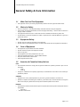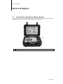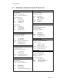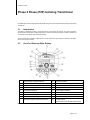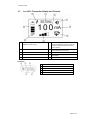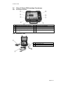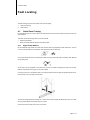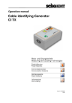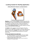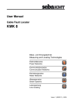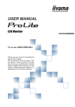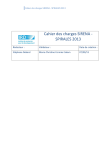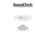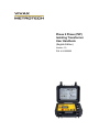
1
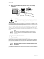
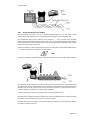
Phase 2 Phase (P2P) Isolating Transformer User Handbook (English Edition) Version 1.0 P/N: 4.04.000060 Table of Content General Safety & Care Information ........................................................................................................... 1 1.1 Who Can Use This Equipment ................................................................................................ 1 1.2 Work-site Safety ...................................................................................................................... 1 1.3 Equipment Safety .................................................................................................................... 1 1.4 Care of Equipment .................................................................................................................. 1 1.5 American & Canadian Safety Notices ..................................................................................... 1 Service & Support ..................................................................................................................................... 2 2.1 Serial Number and Software Revision Number ....................................................................... 2 2.2 Distributors and Service Centers Closest to You: ................................................................... 3 Phase 2 Phase (P2P) Isolating Transformer ............................................................................................. 4 3.1 Introduction ............................................................................................................................. 4 3.2 vLocPro2 Receiver Main Display ............................................................................................ 4 3.3 Loc-10Tx Transmitter Display and Controls ............................................................................ 5 3.4 Phase 2 Phase (P2P) Isolating Transformer ........................................................................... 6 3.4.1 Front Panel Controls ............................................................................................................ 6 3.4.2 Connection Leads ................................................................................................................ 6 Fault Locating ........................................................................................................................................... 7 4.1 Cable Route Tracing ............................................................................................................... 7 4.1.1 Signal Clamp Method .......................................................................................................... 7 4.1.2 Direct Connection Method Using the Phase 2 Phase (P2P) Isolating Transformer ............. 8 4.2 4.2.1 Fault Locating.......................................................................................................................... 8 Actual Connection to Link Box ............................................................................................. 9 1 General Safety and Care Information General Safety & Care Information 1.1 Who Can Use This Equipment This equipment must only be used by people suitably trained in the use of pipe and cable locators. 1.2 Work-site Safety Use your companies, or other applicable safety codes and rules when using this equipment. Unless having the required authorization, license and appropriate training – do NOT make connections to any pipe, cable or conductor. The equipment should not come in contact with corrosive or hazardous chemicals, or gases, dust. Do NOT directly connect this equipment to cables or pipes that have a potential difference to ground of greater than 20V AC. 1.3 Equipment Safety Do NOT open the enclosures (housings) of the equipment. Do NOT hold any uninsulated portion of the connection leads & clips when the equipment is switched on. 1.4 Care of Equipment Use equipment only as directed in this User Handbook. Do NOT immerse any part of this equipment in water. Store in a dry place. Keep equipment in the case provided when not in use. If left for prolonged period of time – remove alkaline batteries. Keep unit clean and free of dust and dirt. Protect against excessive heat. 1.5 American & Canadian Safety Notices USA This transmitter and receiver comply with the general conditions of operation, pursuant to part 15 of the FCC Rules. o CATIII o UL94 HB Changes or modifications not expressly approved by the manufacturer could void the user’s authority to operate the products. CANADA Equipment is for use by trained operators only, and not for general household or consumer use. Operation is subject to the following two conditions: (1) this device may not cause interference, and (2) this device must accept any interference that may cause undesired operation of the device. EUROPE Vivax-Metrotech confirms that the location system is compliant with relevant provision of European directive 2004/108/EC. o EN 61326-1 o EN 61010-1 EN 61010-2 Page 1 of 9 2 Service & Support Service & Support 2.1 Serial Number and Software Revision Number Always quote your receiver and transmitter model number, serial number and software revision number when requesting product support. They can be found as follows: (for reference only) 1 Model & Serial Number Page 2 of 9 2 Service & Support 2.2 Distributors and Service Centers Closest to You: World Headquaters, United State of America China Vivax-Metrotech Corporation 3251 Olcott Street, Santa Clara, CA 95054, USA Website : www.vivax-metrotech.com Leidi Utility Supply (Shanghai) Ltd. No. 780, Tianshan Rd, Shanghai, China 200051 Sales & Sales Support: T/Free : 800-446-3392 Tel : +1-408-734-1400 Fax : +1-408-734-1415 Email : [email protected] T/Free Tel Fax Website Email : 4008-206-719 : +86-21-5235-3001 : +86-21-5235-8365 : www.leidi.cn : [email protected] Service & Repairs: T/Free : 800-638-7682 Tel : +1-408-962-9990 Fax : +1-408-734-1799 Email : [email protected] Europe SebaKMT Seba Dynatronic Mess-und Ortungstechnik GmbH Dr.-Herbert-Iann-Str. 6, 96148 Baunach, Germany Australasia Tel Vivax-Metrotech AUS Unit 1, 176 South Creek Road, Cromer NSW 2099, Australia Fax : +49-9544-2273 Website : www.sebakmt.com Email : [email protected] Tel France : +61-2-9972-9244 Fax : +61-2-9972-9433 Website : www.vivax-metrotechaus.com Email : [email protected] [email protected] Vivax Canada Inc. 41 Courtland Ave Unit 6, Vaughan, ON L4K 3T3, Canada Tel Fax Website Email : +1-289-846-3010 : +1-905-752-0214 : www.vivax-metrotech.com : [email protected] Central/South America and the Caribbean Ventas para América Latina 3251 Olcott Street, Santa Clara, CA 95054, USA Website : www.vivax-metrotech.com T/Free Tel Fax Email Vivax-Metrotech SAS Technoparc ‐ 1 allée du Moulin Berger, 69130 Ecully, France Tel Fax Canada : +49-9544-680 : +33(0)4 72 53 03 03 : +33(0)4 72 53 03 13 Website : www.vivax-metrotech.com Email : [email protected] United Kingdom Vivax-Metrotech Ltd. Unit 18-19, Woodside Road, South Marston Industrial Estate, Swindon, SN3 4WA, UK Free Phone: 0800 0281811 Tel : +44(0)1793 822679 Website : www.vivax-metrotech.com Email : [email protected] : 800-624-6210 : +1-408-734-1400 : +1-408-743-5597 : [email protected] Page 3 of 9 3 Phase 2 Phase Phase 2 Phase (P2P) Isolating Transformer Vivax-Metrotech Phase to Phase fault locating Guide using the vLocPro2 Kit and Phase 2 Phase (P2P) Isolating Transformer. 3.1 Introduction This guide is intended to be used in conjunction with the vLocPro2 full user manual. The vLocPro2 together with the Phase 2 Phase (P2P) isolating transformer is used for detecting the position of phase to phase short circuit faults on low voltage three phase buried cable. Some brief reminder information regarding the vLocPro2 location kit is given below but this does not replace the full vLocPro2 user manual. 3.2 vLocPro2 Receiver Main Display 1 Digital Display of Signal Response 10 Frequency Select 2 Loudspeaker Status 11 Gain Control (reduce gain) 3 Bluetooth and GPS Signal Quality 12 On/Off Control 4 Alkaline/Rechargeable Battery Status 13 Compass Line Direction Indicator 5 Peak Signal Indication 14 Left vs Right Indication 6 Frequency 15 db Gain Setting 7 Location Mode Select 16 Analogue Display of Signal Response 8 Gain Control (increase gain) 17 Continuous Depth/Current 9 Information Depth/Current Measurement 18 Location Mode (Peak, Null, Sonde, Broad, Peak Arrows) Note: Bluetooth function is available in vLoc receivers with Bluetooth module only. Page 4 of 9 3 Phase 2 Phase 3.3 Loc-10Tx Transmitter Display and Controls 1 Frequency Being Transmitted (200 kHz available in some country) 6 2 Digital Read Out (mA, volts, ohms) 7 3 Loudspeaker Level 8 4 Units (mA, volts, ohms) 9 5 Mode Indication Output Setting (Step) (filled box indicates current level has been reached, empty box indicates requested current level has not been achieved) Low Power Indicator (enabled automatically when battery becomes one bar) Battery Status High Voltage Warning (output is enabled for high voltage) Pushbutton 1 On/Off Control 2 3 Output Decrease Frequency Select 4 Output Increase 5 Information (Volume, mAmps, volts, ohms) Page 5 of 9 3 Phase 2 Phase 3.4 Phase 2 Phase (P2P) Isolating Transformer 3.4.1 Front Panel Controls 1 2 Output Current Meter 33kHz trace signal protected to 500V AC 6 7 Fuse Protection (3.15A) Connection to vLoc transmitter 3 Ground Connection 8 On/Off 4 5 High Voltage (20V AC) Warning LED Low Frequency Locate Output Phase to Phase Fault 9 Battery (PP3 9V) 1 Earth Lead 2 Fused Leads 10A FF 3 Connection to vLoc Tx Output 3.4.2 Connection Leads Page 6 of 9 4 Fault Locating Fault Locating The fault locating process can be broken down into two stages: 1. Cable route tracing 2. Fault locating 4.1 Cable Route Tracing It is important that the route of the cable is carefully marked out as the locator needs to follow the route of the cable precisely. The cable can be traced using either one of two methods: Signal Clamp Method Direct Connection Method using the P2P 33kHz output 4.1.1 Signal Clamp Method Set the transmitter and receiver to 33 kHz mode. Set the antenna configuration to Peak with Arrows. The icon on the top left indicates the mode selected. Use the Return button to select this. Pushbutton Icon Connect the Clamp antenna to the transmitter output and clamp around the base of the faulty cable, BELOW the grounding point. Set the output of the transmitter to the second bar. (This is not critical but keeping the output low will save batteries and will reduce stray pick up onto other cables) If coming out of a box or transformer station, do a sweep around the area to detect the greatest signal current. Use the locator in the orientation shown below. Confirm the strongest signal by pressing the “i” button which will then display the depth and current. The cable with the greatest signal current will be the one to trace. Continue to trace and mark out the route of the cable. Page 7 of 9 4 Fault Locating 4.1.2 Direct Connection Method Using the Phase 2 Phase (P2P) Isolating Transformer WARNING Only authorized and trained personnel should attempt to connect to live services. Always adhere to company regulations and use appropriate protective clothing. Connect the system as above ensuring the Grounding cable is connected first and removed last. The station or link box ground should be used for this purpose. The signal ground wire can also be connected to this point but an independent ground may produce less ambiguous results. Switch on the transmitter and set to 33kHz. Also switch on the P2P transformer. The reading on the meter should be just a few milliamps as the cable connected to will not be grounded. However, there should be sufficient signal current to trace. Sometimes a small residual current reading will be shown on the meter, this is normal. NOTE Note that the high voltage LED will not illuminate even if connected to a live cable. This is because it is associated with the other output ie the P2P output connections. Trace the cable as in section “Signal Clamp Method” above. 4.2 Fault Locating Having mapped out the route of the cable the process of fault locating can begin. First confirm which is the faulty pair. Check that the voltage between the shorted phases is less than 20V AC. If the voltage is above 20V the fault is not a complete short in which case this method will probably not work. (The red LED on the P2P will also illuminate above 20V AC). NOTE Note that if the P2P output is connected to a voltage above 100V AC the internal fuses may blow. Connect the P2P to the transmitter as below. Ensure the Green ground lead is connected to the station/link box ground first. This should also be the last cable to be removed when detaching the unit from the cable under test. Page 8 of 9 4 Fault Locating 4.2.1 Actual Connection to Link Box Set the transmitter and locator to one of the following frequencies 980Hz or 1.17 kHz. Either of these frequencies is suitable although only one of these frequencies is available on some transmitter units. Set the transmitter output current to maximum current using the “+”, “-“ keys. The value on the transmitter display should settle somewhere between 700mA and 1A. This is not the current being injected into the cable. Look on the P2P meter to see the injected current. This should typically be just below 2000mA (2A). If less than 1000mA (1A) the technique may not work. Now set the frequency to match the transmitter and gain on the cable locator to approximately 65dB using the “+” “-“ buttons. Set the antenna configuration to single antenna. Pushbutton Icon Position the locator above the cable as below. Note, this is 90 degrees to the normal cable locating orientation. Keep the locator in this orientation and slowly move along the length of the cable. Note that the signal on the bar graph will rise and fall in sympathy with the twist of the cable. Adjust the sensitivity to keep the rise and fall within the range of the bar graph. Once this is set it should not be necessary to change it unless there is a change of cable type or the depth of the cable changes dramatically. At the fault there will be a sharp rise in signal and then close to nothing after the fault. Be careful as there will also be a sharp rise at cable joints. These can be distinguished from a fault as the signal will continue to rise and fall after the joint if there is no fault at this point. If possible always confirm the position of the fault by applying the signal from the other side of the fault and work back to the fault from this end. Page 9 of 9 Notes: _________________________________________________________________ _________________________________________________________________ _________________________________________________________________ _________________________________________________________________ _________________________________________________________________ _________________________________________________________________ _________________________________________________________________ _________________________________________________________________ _________________________________________________________________ _________________________________________________________________ _________________________________________________________________ _________________________________________________________________ _________________________________________________________________ _________________________________________________________________ _________________________________________________________________ _________________________________________________________________ _________________________________________________________________ _________________________________________________________________ Vivax-Metrotech Corporation 3251 Olcott Street, Santa Clara, CA 95054, USA Website: www.vivax-metrotech.com