1
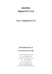
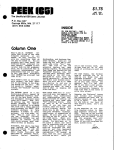
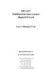
MPC-3004
4 Axes Positioning card
User’s Manual (V1.4)
健昇科技股份有限公司
JS AUTOMATION CORP.
台北縣汐止市㆗興路 100 號 6 樓
6F,NO.100,CHUNG-SHIN RD.
SHI-TSU,TAIPEI,TAIWAN,R.O.C.
TEL:886-2-2647-6936
FAX:886-2-2647-6940
http://www.automation.com.tw
E-mail:[email protected]
[email protected]
Export: [email protected]
CONTENTS
1.
2.
3.
4.
FORWARD ........................................................................................................................................ 2
PACKING LIST ................................................................................................................................ 2
FEATURES........................................................................................................................................ 3
SPECIFICATIONS ........................................................................................................................... 4
4.1
MPC-3004 MAIN CARD ........................................................................................................... 4
4.2
MPC DIN RAIL MOUNTED WIRING BOARD ...................................................................... 4
5.
LAYOUT ............................................................................................................................................ 5
5.1
MPC-3004 MAIN CARD LAYOUT ....................................................................................... 5
5.2
DIN RAIL MOUNTED WIRING BOARD LAYOUT .............................................................. 5
6.
PIN DEFINITIONS........................................................................................................................... 6
CONNECTOR FRONT VIEW ................................................................................................. 6
6.1
6.2
PIN DEFINITIONS..................................................................................................................... 6
7.
I/O INTERFACE DIAGRAM.......................................................................................................... 7
7.1
WIRING BOARD INPUT DIAGRAM ...................................................................................... 7
7.2
WIRING BOARD OUTPUT DIAGRAM .................................................................................. 7
7.3
7.4
8.
9.
MPC-3004 PULSE DRIVING METHOD FOR SINGLE END INPUT:.................................. 8
PULSE DRIVING METHOD FOR DIFFERENTIAL INPUT: ............................................... 8
EXTERNAL WIRING DIAGRAM................................................................................................. 9
HARDWARE SETTINGS .............................................................................................................. 10
9.1
CARD ID SETTING................................................................................................................. 10
9.2
SINGLE/DUAL PULSE MODE SETTING............................................................................ 10
10. HOW TO USE DOS DEMO PROGRAM .................................................................................... 11
11. APPLICATIONS ............................................................................................................................. 12
12. DIMENSIONS ................................................................................................................................. 13
12.1 MAIN CARD DIMENSION..................................................................................................... 13
12.2 DIN RAIL MOUNTED WIRING BOARD.............................................................................. 13
13. ORDER INFORMATION .............................................................................................................. 14
14. LAYOUT(OLD)............................................................................................................................... 15
14.1 MPC-3004 MAIN CARD LAYOUT ..................................................................................... 15
14.2 DIN RAIL MOUNTED WIRING BOARD LAYOUT ............................................................ 15
15. I/O INTERFACE DIAGRAM (OLD)............................................................................................ 16
15.1 INPUT DIAGRAM ................................................................................................................... 16
15.2 OUTPUT DIAGRAM ............................................................................................................... 16
15.3 WIRING BOARD INPUT DIAGRAM .................................................................................... 16
15.4 WIRING BOARD OUTPUT DIAGRAM ................................................................................ 16
16. DIMENSIONS(OLD)...................................................................................................................... 17
16.1 MAIN CARD DIMENSION..................................................................................................... 17
1
1. FORWARD
MPC3004 is a PCI bus point to point 4 axes motion control card, which is DSP based design with the
FPGA technology developed by JS Automation Corp.
Owing to the high performance of DSP we call this card “Intelligent card”, MPC3004 consumes less CPU
resource and gives a better performance than other dummy cards.
The practical application consideration makes this card easy to use and easy to wire, the security function
also provides the system integrator a protection of illegal copy of firmware.
other motion control card:
MPC-2004 4 axes point to point motion control card (ISA bus)
Any comment is welcome,
please visit our website: www.automation.com.tw for the up to date informations.
2. PACKING LIST
2.1
2.2
2.3
2.4
2.5
MPC-3004 4 AXES POSITIONING CARD
DEMO CD
SCSI 50P CABLE 150CM.(OPTION 300CM)
DIN RAIL MOUNTED WIRING BOARD
ACCESSORY
2
1
1
1
1
1
3. FEATURES
3.1
3.2
3.3
3.4
3.5
3.6
3.7
3.8
3.9
3.10
3.11
3.12
3.13
3.14
3.15
3.16
PCI plug and play function with card ID for 16 identical cards
On board DSP processor performs multi-task controls with PC’s CPU
On board FPGA deal with real time servo control
Design with high pulse rate and good accuracy of acceleration
Software key (password) protects user’s know-how
Software limit switch blocks safe area (space)
Photo-coupler isolated general I/O and limit switch circuit
Backlash compensation to compensate tolerance on moving parts
Separate parameters setting for Homing and positioning function
Multiple programmable Homing modes
Programmable polarity and enable/disable function to fit different kinds of limit
switch
Absolute and relative positioning mode
Two stop modes included halt and deceleration to stop
Software programmable parameter setting for load_current_position
Scale ratio formula for real distance programming (pulse count implied)
Hardware selectable single or dual pulse mode
3
4. SPECIFICATIONS
4.1
MPC-3004 MAIN CARD
4.1.1
4.1.2
4.1.3
4.1.4
4.1.5
4.1.6
4.1.7
4.1.8
4.1.9
4.1.10
4.1.11
4.1.12
4.1.13
4.1.14
4.1.15
4.1.16
4.1.17
4.1.18
4.1.19
4.1.20
4.2
Input photo-coupler isolation voltage ― 2500Vac 1Min
Data width ― 32 Bits
Control axes ― 4
Card ID ― 4 bits
Specific input ― 3 (LS+, LS-, Home) per axis with photo-coupler
General input ― 8 with photo-coupler
General output ― 8 with photo-coupler and relay contact “a”
Maximum length setting ― 24 Bits (e.g. 16, 777, 215 unit length)
Arithmetic calculation ― 32 Bits
Max. speed of driving pulse ― 1Mhz
Max. acceleration rate ― 4Mhz/sec
Frequency deviation ― ± 0.005% of driving pulse
Max. working distance ― 32 Bits (e.g. ± 2,147,483,647 unit length)
Timer setting range ― 0-60,000ms circulating
I/O connector ― mini SCSI female 50 pins between wiring boards
Connector type ― plugable connector
External supply ― DC 24V± 4V
Operation temp ― 0 to 70° C
Operation humidity ― RH5~95%, non-condensing
Dimension ― 178(W)*115(H)mm, 7.0(W)*4.53(H)in
MPC DIN RAIL MOUNTED WIRING BOARD
4.2.1
4.2.2
4.2.3
4.2.4
External supply ― DC 24V± 4V
On board build-in s.p.s. ― DC+5V 500ma (max)
Operation temp ― 0 to 70° C
General input LED ― 8
4.2.5
4.2.6
4.2.7
4.2.8
4.2.9
General output ― 8 power MOS (1A 120V DC) with LED
Specific I/O LED ― 20
Specific servo control connector ― 4 D-type 9 pin connector
Operation humidity ― RH5~95%, non-condensing
Dimension ― 200(W)*72(H)mm, 7.87(W)*2.83(H)in
4
5. LAYOUT
5.1
MPC-3004 MAIN CARD LAYOUT
Card ID
DIP switch
5.2
CLK select DIP-SW
(Single/Dual pulse mode)
DIN RAIL MOUNTED WIRING BOARD LAYOUT
5
6. PIN DEFINITIONS
6.1
6.2
CONNECTOR FRONT VIEW
PIN DEFINITIONS
Pin
No.
Descriptions
1
+24V (External supplied DC/24V power
input)
+24V (External supplied DC/24V power
input)
+5V (DC/5V output,requlated from
external 24V input)
+5V (DC/5V output,requlated from
external 24V input)
X_CW (CLOCK):CW for dual pulse
mode,CLOCK for single pulse mode
Y_CW (CLOCK):CW for dual pulse
mode,CLOCK for single pulse mode
X_CCW (DIR):CCW for dual pulse
mode,DIRECTION for single pulse mode
Y_CCW (DIR):CCW for dual pulse
mode,DIRECTION for single pulse mode
X_LS+ : Positive over-travel limit switch
input for X axis
Y_LS+ : Positive over-travel limit switch
input for Y axis
X_LS-- : Negative over-travel limit switch
input for X axis
Y_LS-- : Negative over-travel limit switch
input for Y axis
X_HOME : Home limit switch input for X
axis
Y_HOME : Home limit switch input forY
axis
GND ( common terminal for +24V,+5V,
I/P,O/P)
GND ( common terminal for +24V,+5V,
I/P,O/P)
GND ( common terminal for +24V,+5V,
I/P,O/P)
IN0:General purpose input0
IN1:General purpose input1
IN2:General purpose input2
IN3:General purpose input3
IN4:General purpose input4
IN5:General purpose input5
IN6:General purpose input6
IN7:General purpose input7
2
3
4
5
6
7
8
9
10
11
12
13
14
15
16
17
18
19
20
21
22
23
24
25
Pin
No.
Descriptions
GND (common terminal for +24V,+5V,
26 I/P,O/P)
GND (common terminal for +24V,+5V,
27 I/P,O/P)
GND (common terminal for +24V,+5V,
28 I/P,O/P)
GND (common terminal for +24V,+5V,
29 I/P,O/P)
(CLOCK):CW for dual pulse
30 Z_CW
mode,CLOCK for single pulse mode
(CLOCK):CW for dual pulse
31 A_CW
mode,CLOCK for single pulse mode
(DIR):CCW for dual pulse
32 Z_CCW
mode,DIRECTION for single pulse mode
(DIR):CCW for dual pulse
33 A_CCW
mode,DIRECTION for single pulse mode
: Positive over-travel limit switch
34 Z_LS+
input for Z axis。
: Positive over-travel limit switch
35 A_LS+
input for A axis。
: Negative over-travel limit switch
36 Z_LSinput for Z axis。
: Negative over-travel limit switch
37 A_LSinput for A axis。
: Home limit switch input for Z
38 Z_HOME
axis。
: Home limit switch input for A
39 A_HOME
axis。
(common terminal for +24V,+5V,
40 GND
I/P,O/P)
(common terminal for +24V,+5V,
41 GND
I/P,O/P)
(common terminal for +24V,+5V,
42 GND
I/P,O/P)
43 OUT0:General purpose output。
44 OUT1:General purpose output。
45 OUT2:General purpose output。
46 OUT3:General purpose output。
47 OUT4:General purpose output。
48 OUT5:General purpose output。
49 OUT6:General purpose output。
50 OUT7:General purpose output。
6
7. I/O INTERFACE DIAGRAM
7.1
WIRING BOARD INPUT DIAGRAM
+5V
+24Ve
+5Ve
External
Supply +24Ve
4.7K
JP1-JP4
3
EXTG
O.C.
JP1,JP2,JP3,JP4
2-3 Short : I/P 5V Level
1-2 Short : I/P 24V Level
External Inputs
2
1
IN0 / IN1 / IN4 / IN5
EXTG
+5V
+24Ve
External
Supply +24Ve
EXTG
External Inputs
IN2 / IN3 / IN6 / IN
HOME / LS+ / LSEXTG
WIRING BOARD OUTPUT DIAGRAM
+5V
+5Ve
+5Ve
CW / CCW
EXTG
+24Ve
+5Ve
Relay
OUTn
OUT0,OUT1
COMA
O.C.
OUT2,OUT3
COMB
2803
+24Ve
+5Ve
OUTn
Relay
7.2
O.C.
OUT4,OUT5
COMC
OUT6,OUT7
COMD
COMn
2803
7
+5Ve
COMn
+24Ve
OUTn
O.C.
OUT0,OUT1
COMA
O.C.
OUT2,OUT3
COMB
2803
EXTG
+5Ve
OUT4,OUT5
COMC
+24Ve
OUT6,OUT7
COMD
OUTn
O.C.
O.C.
N-MOS
2803
EXTG
7.3
MPC-3004 PULSE DRIVING METHOD FOR SINGLE END INPUT:
<< Active Lo >>
+5V
<< Active Hi >>
Circuit on driver
1
4
2
3
Circuit on driver
CW / CCW
1
4
2
3
CW / CCW
7.4
PULSE DRIVING METHOD FOR DIFFERENTIAL INPUT:
If your driver’s differential input has pull up resistor as the right diagram,direct
connection to cw+/ccw+ is acceptable otherwise external resistor connect as right
diagram is required.
The recommended value for R1~R3 is 4.7K |Ohm.
.
DIFFERENTIAL INPUT ON DRIVER
+5Ve
R1
R2
INPUT FROM WIRING BD.
+
-
NC
R3
INPUT CIRCUIT
8
26LS32
8. EXTERNAL WIRING DIAGRAM
X_CW
X_CCW
EXTG
+5Ve
IN2
IN0
OUT0
OUT2
1
6
2
7
3
8
4
9
5
Mini SCSI cable
from main card
X_DB9F
Y_CW
Y_CCW
EXTG
+5Ve
IN3
IN1
OUT1
OUT3
1
6
2
7
3
8
4
9
5
1 EXTG
O0 1
Load
2 +24V
O1 2
Load
3 EXTG
COMA 3
4 +5V
EXTG 4
DC120VMax *1
O2 1
1 IN0
2 IN1
Y_DB9F
3 IN2
Z_CW
Z_CCW
EXTG
+5Ve
IN6
IN4
OUT4
OUT6
1
6
2
7
3
8
4
9
5
+5Ve
IN7
IN5
OUT5
OUT7
COMB 3
EXTG 4
4 IN3
5 EXTG
O4 1
O5 2
Z_DB9F
A_CW
A_CCW
EXTG
O3 2
1
6
2
7
3
8
4
9
5
for easy connection
of servo drivers,
4 individual D-9
connectors are
provided.
1 IN4
COMC 3
2 IN5
EXTG 4
3 IN6
O6 1
4 IN7
O7 2
5 EXTG
COMD 3
EXTG 4
SERVO
DRIVER
1 +5V
A_DB9F
2 Z_CCW
SERVO MOTOR
X_CW 3
4 EXTG
EXTG 4
5 Z_LS+
X_LS+ 5
6 Z_LS-
X_LS- 6
1 +5V
2 A_CCW
** Be sure to check
the output type of your wiring board
X_HOME 7
+5V 1
Y_CCW 2
3 A_CW
Y_CW 3
4 EXTG
EXTG 4
5 A_LS+
Y_LS+ 5
6 A_LS-
Y_LS- 6
7 A_HOME
9
X_CCW 2
3 Z_CW
7 Z_HOME
*1 connection example
for power MOSFET output
+5V 1
Y_HOME 7
9. HARDWARE SETTINGS
9.1
CARD ID SETTING
Since PCI cards have plug and play function, the card ID is required for programmer to
identify which card he/she will control without knowing the physical address assigned
by the Windows. A 4 bits DIP switch for distinguishing the 16 identical card.
The following example sets the card ID at 12.
DIP SW SETTING:(ID=12)
8
4
2
Weighting
1
ON
0
1
1
2
3
E
D
C
B
A
4
F 0 1
9 8 7
2
3
4
5
6
CARD_ID
9.2
SINGLE/DUAL PULSE MODE SETTING
9.2.1
1_CLK(4DIP-SW):Single/Dual pulse mode setting
Any bit set “on” means the corresponding axis in dual pulse mode ,otherwise single
pulse mode.
The following example sets Y,A axes in Single pulse mode (CLOCK,DIRECTION)and
both X&Z axes in Dual pulse mode (CW,CCW)
ON
Dual
Single
1
2
3
4
X
Y
Z
A
10
10. HOW TO USE DOS DEMO PROGRAM
10.1
BEFORE USING THE DEMO PROGRAM
The demo program is provided to the user with the purpose of familiar the functions of
MPC card. You should setup the driver and dll in windows to register the resources.
Since the demo program is implemented in DOS environment, the card address should
be get from “settings->control panel->system->device manager->MPC3004”.
10.2
START UP:
Execute the demo program MPC3004.exe and then key in the card address.
If press “enter” without any card address data , the default address is 200H.
There are four blocks in the screen: motion control, speed adjustment, global i/o,
security
10.3
All the functions are “one stroke” command, you only press the key data as it is in the
bracket [ ], you will get a prompt and follows its instruction everything is ok.
11
11. APPLICATIONS
11.1
11.2
11.3
11.4
11.5
11.6
Control AC/DC servo motor/driver with pulse type input
Control various of stepping motor (PM/Hybrid/Micro-step)
Any combination mixed control servo and stepping motor
Control 4 servos with one card, easy to add on more cards to control more devices
As multiple of frequency generator up to 1 MHZ
Control precision machinery, or semi-conductor package equipment
12
12. DIMENSIONS
12.1
MAIN CARD DIMENSION
12.2
DIN RAIL MOUNTED WIRING BOARD
13
13. ORDER INFORMATION
PRODUCT
MPC-3004
MPC-3004 DMO
MPC-3004 WIN
MPC-3004 LVW
MPC-3004 DIN
DESCRIPTIONS
4 axes of servo/step positioning control card
Demo program of MPC-3004 card for DOS (free with user manual)
Dll (VB/VC/C++ Builder) of MPC-3004 card for Win95/98/NT
Vi of MPC-3004 card for LabVIEW
4 axes in one DIN RAIL MOUNTED wiring board
14
14. LAYOUT(OLD)
14.1
MPC-3004 MAIN CARD LAYOUT
14.2
DIN RAIL MOUNTED WIRING BOARD LAYOUT
15
15. I/O INTERFACE DIAGRAM (OLD)
15.1
INPUT DIAGRAM
MPC-3004
Wiring board
+5V
+24Ve
+5Ve
EXTERNAL
Supply +24Ve
3.3K
4.7K
1
GND
4
JP6 / JP7 :
2-3 Short : I/P 5V Level
1-2 Short : I/P 24V Level
330
3
EXTERNAL
INPUTS
1
IN0 / IN1 / IN4 / IN5
2
2
3
O.C.
JP6 / JP7
15.2
GND
OUTPUT DIAGRAM
MPC-3004
Wiring board
+24Ve
+5V
4
1
Relay
OUTn
3
2
B
O.C.
2
3
17
2
1
JP1 / JP2 / JP3 / JP4
15.3
WIRING BOARD INPUT DIAGRAM
MPC-3004
Wiring board
+5V
+24Ve
EXTERNAL
Supply +24Ve
3.3K
1
4
GND
EXTERNAL
INPUTS
2
3
330
IN2 / IN3 / IN6 / IN7
HOME / LS+ / LSGND
15.4
WIRING BOARD OUTPUT DIAGRAM
MPC-3004
Wiring board
+5Ve
+5V
GND
CW/ CCW
GND
16
16. DIMENSIONS(OLD)
16.1
MAIN CARD DIMENSION
17