1
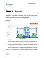
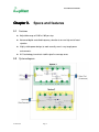
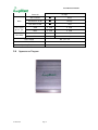
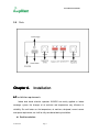
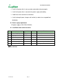
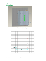
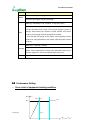
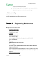
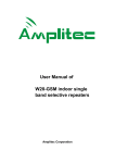
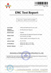
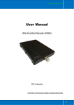
10
User Manual of
W10-GD
Amplitec Corporation
User Manual of W10-GD
CATALOGUE
CHAPTER 1. SAFETY WARNNING ................................................................................ 2
CHAPTER 2. SUMMARY ................................................................................................. 3
CHAPTER 3. SPECS AND FEATURES ........................................................................... 4
3.1
FEATURES ............................................................................................................. 4
3.2
SYSTEM DIAGRAM .................................................................................................. 4
3.3
SPECIFICATION ...................................................................................................... 5
3.4
APPEARANCE DIAGRAM .......................................................................................... 6
3.5
PORTS .................................................................................................................. 7
CHAPTER 4. INSTALLATION .......................................................................................... 7
4.1 INSTALLATION REQUIREMENTS..................................................................................... 7
4.2 INSTALLATION ............................................................................................................ 8
4.3 CONNECTION........................................................................................................... 10
4.4 SYSTEM INSPECTION ................................................................................................ 11
CHAPTER 5. REPEATER SETTING ............................................................................. 11
5.1 POWER SUPPLY CONNECTION ................................................................................... 11
5.2 PERFORMANCE SETTING .......................................................................................... 12
CHAPTER 6. ENGINEERING MAINTENANCE ............................................................. 14
6.1 OPERATION AND MAINTENANCE ................................................................................. 14
6.2 EMERGENCY DEALING .............................................................................................. 15
6.3 MAINTAINING DIRECTIONS ......................................................................................... 15
Confidential
Page 1
User Manual of W10-GD
Chapter 1.
Safety Warnning
Users must follow the below principles:
1. Repeater should follow system requirement of communication equipment, assure
good groundings and lightning protection.
2. The power supply voltage of repeater should meet the standards of security
requirement; any repeater-operator can operate only after cutting power in advance.
Only the professional can operate electrified.
3. Do not dismantle machine, maintain or displace accessories by yourself, because in
this way, the equipment may be damaged or even get an electric shock.
4. Do not open the repeater, touch the module of repeater, even not to open the cover
of module to touch the electronic component, the components will be damaged due
to electrostatic
5. Please keep away from heating-equipment, because the repeater will dissipate heat
when working. And do not cover repeater with anything that influences
heat-dissipation.
Confidential
Page 2
User Manual of W10-GD
Chapter 2.
Summary
In mobile communication, it is inevitable that macro-cell coverage cannot cover weak
or dead zones; to use repeater is a good choice in these areas. Single band selective
repeaters mainly applied in covering small blind and weak zones.
W10-GD is a good choice for VIP rooms, offices, houses, restaurants, apartments,
packing, etc.
Picture 2.1 Application
W10-GD enhances consumer satisfaction greatly with its integrated design,
compact size, easy engineering and rapid installation and debugging,
W10-GD is made with the characteristics of industrial aesthetic design, and thus
can be installed in high-class places as a decoration.
SAW filter technology enables it to amplify only the targeted operator’s signals and
reject all the others effectively, it is, therefore, an optimal solution for coverage
extension.
Confidential
Page 3
User Manual of W10-GD
Chapter 3.
3.1
Specs and features
Features
Adjustable range of 31dB at 1dB per step.
Advanced digital controlled frequency selection to ensure high out of band
rejection.
Highly stable power design, to work normally even in very tough power
environments.
3.2
ALC technology to maintain stabile signal in coverage areas
System diagram
Confidential
Page 4
User Manual of W10-GD
3.3
Specification
Items
Frequency
Range
Bandwidth
Output Power
Gain
Ripple
VSWR
Uplink
Downlink
GSM
890.1 ~ 901.1 MHz
935.1 ~ 946.1 MHz
DCS
1760.3 ~ 1772.3 MHz
1855.3 ~ 1867.3MHz
GSM
11 MHz
11 MHz
DCS
12 MHz
12 MHz
GSM
10±2 dBm
10±2 dBm
DCS
10±2 dBm
10±2 dBm
GSM
60±2 dB
60±2 dB
DCS
60±2 dB
60±2 dB
GSM
≤ 3 dB
≤ 3 dB
DCS
≤ 3 dB
≤ 3 dB
GSM
≤2
≤2
DCS
≤2
≤2
Max. Input Power Without Damage
-10 dBm
± 600 KHz
≤ +40 dB
≤ +40 dB
± 1 MHz
≤ +35 dB
≤ +35 dB
± 5 MHz
≤ +25 dB
≤ +25 dB
± 600 KHz
≤ +40 dB
≤ +40 dB
± 1 MHz
≤ +35 dB
≤ +35 dB
± 5 MHz
≤ +25 dB
≤ +25 dB
Intermodulation
Products
GSM
≤ -36 dBm
≤ -36 dBm
DCS
≤ -30 dBm
≤ -30 dBm
Spurious
Emission
9KHz~1GHz
≤ -36 dBm
≤ -36 dBm
1GHz~12.75GHz
≤ -30 dBm
≤ -30 dBm
1~10 dB
∣ △ ∣ ≤ 1 dB
∣ △ ∣ ≤ 1 dB
10~20 dB
∣ △ ∣ ≤ 1 dB
∣ △ ∣ ≤ 1 dB
20~25 dB
∣ △ ∣ ≤ 1.5 dB
∣ △ ∣ ≤ 1.5 dB
1~10 dB
∣ △ ∣ ≤ 1 dB
∣ △ ∣ ≤ 1 dB
10~20 dB
∣ △ ∣ ≤ 1 dB
∣ △ ∣ ≤ 1 dB
20~25 dB
∣ △ ∣ ≤ 1.5 dB
∣ △ ∣ ≤ 1.5 dB
∣ △ ∣ ≤ 2 dB
∣ △ ∣ ≤ 2 dB
Out of Band
Gain(GSM)
Out of Band
Gain(DCS)
ATT step of 1
dB (GSM)
ATT step of 1
dB (DCS)
ALC Active 10dB
LED Indication
Confidential
Power On
Green
Page 5
User Manual of W10-GD
Power Off
—
—
—
ALC not Active
Alarm
ALC Active 5~10 dB
ALC Active >15dB
Noise Figure
@ max. gain
Time Delay
3.4
Green
Orange
Red
GSM
≤ 6 dB
≤ 6 dB
DCS
≤ 6 dB
≤ 6 dB
GSM
≤ 5 µs
≤ 5 µs
DCS
≤ 5 µs
≤ 5 µs
Power Supply
DC:9 V / 3 A
RF Connector
N-Female
Operating Temperature
-10℃ ~ +55℃
Appearance Diagram
Confidential
No Light
Page 6
User Manual of W10-GD
3.5
Ports
Chapter 4.
Installation
4.1 Installation requirements
Indoor dual band selective repeaters W20-GD are mainly applied as indoor
coverage system, the changes of air moisture and temperature may influence its
reliability. So such factors as the temperature, air moisture, dustproof, current source
and space requirement, etc shall be fully considered during installation.
Position selection
Confidential
Page 7
User Manual of W10-GD
Install in the place that is not easy to be reached by irrelevant people.
Install at the place that is convenient for power supply and cabling.
Avoid heat source and moist environment
Install at drought space, hang on wall vertically in order to assure good heat
distribution.
Power supply requirement
AC power supply of 160~264V, 50/ 60Hz
Installation tools and accessories
Series
item
specification
Quantity
Remarks
1
Expanding plug
M7
4
Accessories
2
Tapping screw
M6*40
4
Accessories
3
Spinner
4
Waterproof tape
5
Ruler
1
measurement and installation of hole
6
Percussion drill
1
drilling on wall
4.2 Installation
Confidential
Page 8
User Manual of W10-GD
Picture 4.1 Installation diagram
Confidential
Page 9
User Manual of W10-GD
Picture 4.2 Hole positions
Installation Steps:
A) Use percussion drill to make four Φ6 holes on the wall according to
above hole diagram.
B) Fill the holes with expanding plug
C) Put the tapping screw through the holes and fit tightly with the
expanding plug, and fasten the repeater onto the wall.
D) Make sure that the installation is firm and correct
4.3 Connection
Connection of RF cable
Input Port : donor antenna cable is connected with BS Port;
Output Port : service antenna cable is connected with Output Port;
Grounding
Please connect one end of a copper wire with the intersection size of 16mm2
with the grounding screw, and the other end with the grounding system of the
building. It is requested that the grounding impedance shall be less than
10Ohm.
Power supply connection
Installation of air switch is recommended for the convenience of power supply
switch off.
Please use three-pin plug to assure good grounding
Please use the grounding screw, nut, washer to connect the grounding wire and
repeater shell Lightening Arrestor can be installed if necessary
Confidential
Page 10
User Manual of W10-GD
Picture 4.3
Power supply connection
4.4 System inspection
The followings should be checked after installation:
Grounding impedance<10Ω;
Antenna socket, cable are well grounded;
Power supply lightening protection
Building lightening protection
Antenna lightning Protection.
Chapter 5.
Repeater setting
Please check whether the connection of RF cable is correct (donor antenna connected to Input
Port, service antenna connected to Output Port), and whether every port is stable. After affirmation,
please go along the followings:
5.1 Power supply connection
After power supply connection, check ALARM and POWER indicators first.
Status and definition of POWER indicators:
Status
Green
Off
Definition
Normal
DC power problem
Status and definition of ALARM indicators:
Confidential
Page 11
User Manual of W10-GD
Status
Definition of ALARM
Meaning: working in linearity
Green
attention: Input signals may be not enough
Meaning: overloading or self oscillation, strong input signals
Attention: cut the connection of equipment and service antenna, then
connect the Output Port to load, if the red light changes to green or
Red
orange, which means the isolation of donor antenna and service
antenna is not enough, then please adjust the isolation.
If the red light still turning on that means over accepting of donor
antenna or strong interference, then please adjust the place of donor
antenna..
Meaning: it is working in linearity
Orange
Notice: Please adjust MGC to increase the attenuation value, till you
find the “edge point”, and let the repeater work at this point.
Off
Repeater break down
5.2 Performance Setting
Curve chart of equipment working condition
POutput Power
Edge Point
Pmax
Confidential
Page 12
(Pinput Power-VATT)
User Manual of W10-GD
Picture 5.1
Curve of output power, input signal and attenuation value
:
POutput Powe: output power
Pinput Power: input power
VATT: attenuation vale
Pinput Power -VATT: input power—attenuation value
Pmax: output power rating
Downlink gain setting
As for the downlink working performance, “orange” is a good working point. At this time,
downlink output power and coverage effect are stable.
But from another point of view, we hope the equipment is as far as possible away from
overloading status of “red” (thus the equipment would hold higher interference depression ability).
So we try our best to set the equipment near “edge point” when engineering.
Setting of “edge point”: (Switch on the power supply after connection with donor antenna and
coverage antenna, and observe ALARM indicator.)
■ If it shines “orange”, use 1dB as stepping to increase attenuator until “green” turns on, then
decrease 1~3dB attenuation value until “orange” turns on. The setting of downlink gain can
reach the perfect status.
■ If it shines “green” then,
◆ To check whether the attenuation value has been set, if it is, use 1dB as stepping to
decrease attenuation until the “orange” turns on, then the downlink gain can reach the perfect
status.
◆ But if attenuation is not set, it indicates that the input power is not enough.
Confidential
Then please check coverage effect first, if the coverage effect is good, the
Page 13
User Manual of W10-GD
engineering has reached expecting target
But if the coverage effect is not so good, the donor antenna should be
adjusted until “orange” turns on or the effect reaches the target.
Uplink gain setting
Uplink gain is set based on downlink gain..
Standards: uplink attenuation value=downlink attenuation value
Chapter 6.
Engineering Maintenance
6.1 Operation and maintenance
Equipment Disassembly
Close the outside air switch
Plug off the power supply
Cleaning
Close the outside air switch
Plug off the power supply.
Do not use liquid materials to clean the equipment to avoid short circuit;
Please use dry dishclout
Grounding
Using grounded power plug (three-pin plug)
Power supply
Please make sure the voltage and frequency comply with the repeater requirement.
Component replacement
Please do not maintain or replace components by yourself, otherwise may get an
electric shock. Only the authorized professional can maintain and replace the
components.
Confidential
Waterproof and moist proof
Page 14
User Manual of W10-GD
Please do not turn on or off the booster in moist environment when its door is
opened.
6.2 Emergency dealing
Switch off is recommended during following situations:
The power supply is not normal
Liquid flows into the equipment;
Working conditions is not normal, (overheating, abnormal smelling, abnormal
sundries)
Closet damage
Performance decreasement
Near to fire
Flooding
6.3 Maintaining directions
Please check the booster step by step according to below processes, to find out the
problem with the repeater.
Abnormal performance
LED check
Abnormal
Improve the feeder
system
Confidential
Green
Red
Feeder system
inspection
Isolation
inspection
Off
Power supply
inspection
Page 15
Normal
Strong interference near donor
Normal
Abnormal
Improve the power supply
system
User Manual of W10-GD
Confidential
Page 16