Download How to use PhaserMatch
Transcript
User Manual Release Note PhaserMatch™ Copyright © Tektronix, Inc. Printed in the U.S.A. Unpublished rights reserved under the copyright laws of the United States. Contents of this publication may not be reproduced in any form without permission of Tektronix, Inc. November 1996 Part Number 070-9270-82 New features and updates Installing the PhaserMatch application Refer to the following table to locate the instructions in this release note for installing and using your printer with the PhaserMatch application. Printer Macintosh installation instructions Windows installation instructions Using the PhaserMatch application Phaser 480X page 2 page 3 page 8 Phaser 450 page 2 page 3 page 8 and page 9 Phaser 300X page 2 page 3 page 8 Phaser 600 page 2 page 7 page 8 Other features ■ Hints and tips for using Calibration Curves See page 10 in this release note for information on using the curve editing feature. ■ Using the Send Profile command This command has improved performance over the description in the PhaserMatch User Manual. See page 12 in this release note for details. ■ Printing a densitometry test print See page 13 in this release note for information on making a test print on your target printing device. ■ Printing with custom profiles See page 13 in this release note for instructions on printing custom profiles you created in the PhaserMatch application. User Manual Release Note 1 Installing the PhaserMatch application: Macintosh Phaser 480X, Phaser 450, Phaser 300X, and Phaser 600 printers The PhaserMatch application for Macintosh is compatible with Apple Macintosh II computers, or later, including PowerPCs. Refer to the instructions in your printer’s manuals for installation instructions. ■ Phaser 480X printers The installer program for the PhaserMatch application is on the printer’s CD-ROM. Refer to the PhaserMatch User Manual for more information. ■ Phaser 450 printers The installer program for the PhaserMatch application is on the printer’s CD-ROM. Refer to the Phaser 450 Drivers and Utilities Printing Reference manual for more information. ■ Phaser 300X printers The installer program for the PhaserMatch application is on the printer’s CD-ROM for the extended features option. Refer to the Phaser 300X Drivers and Utilities Printing Reference manual for more information. ■ Phaser 600 printers The installer program on the printer’s CD-ROM installs the PhaserMatch application. Refer to the Phaser 600 Color Printer User Manual for more information. The files created by the PhaserMatch application are stored in the following locations: 2 PhaserMatch ■ A PhaserMatch folder inside a PhaserTools folder created by the installer application. ■ A PhaserMatch folder in the Preferences folder, in the Extensions folder, inside the System Folder on your hard disk. 
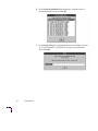
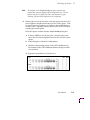
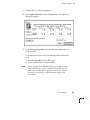
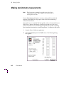
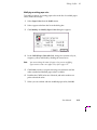
Installing the PhaserMatch application: Windows Phaser 480X, Phaser 450, and Phaser 300X printers Use the following instructions to install PhaserMatch for Windows for these printers: ■ Phaser 480X printers ■ Phaser 300X printers ■ Phaser 450 printers Note If you have an older version of the PhaserMatch application installed on your computer, you should delete its icon from the existing Phaser Tools Group, then delete the Phaser Tools Group. Any saved calibrations or profiles will be available for use in the new version of PhaserMatch in the new PhaserTools Group after installation. 1. Start Windows. 2. Insert the appropriate printer’s CD-ROM into your computer’s CD-ROM drive. 3. From the File Manager, select the drive the CD-ROM is in, followed by the PHSRMTCH directory. 4. Locate the SETUP.EXE file; double-click the file to start the installer. 5. At the Start Installation dialog box, click Yes to install now. User Manual Release Note 3 4 PhaserMatch 6. In the Select Installation Drive dialog box, select the drive to install the software to, then click OK. 7. In the Setup dialog box, select the directory to install the software in. Use the default C:\PHSRMTCH, or type a new path name. Then click OK. 8. In the Icon Installation dialog box, click one of the buttons to determine the group where you want the PhaserMatch application to reside. You can change your mind and return to this dialog box. ■ Click the Use Existing Group button to use an existing group. The Installer looks for an existing PhaserTools group. Select a group from the list, then click OK. Or, click Go Back to return to the Icon Installation dialog box. ■ Click the Create New Group button to use either the default PhaserTools group name or type a new group name. Then click OK. Or, click Go Back to return to the Icon Installation dialog box. User Manual Release Note 5 9. At the Installation Complete message, click Yes to exit the installation program and open a README document about this procedure; click No to exit the installation program. The PhaserMatch application is available in the group you specified. The files created by the PhaserMatch application are stored in the following locations: 6 PhaserMatch ■ Windows 95: PhaserMatch files are stored in the WIN95/PHSRMTCH directory. ■ Windows 3.1: PhaserMatch files are stored in the WINDOWS/PHSRMTCH directory. Installing the PhaserMatch application: Windows Phaser 600 printers Use the following instructions to install PhaserMatch for Windows for Phaser 600 printers. The PhaserMatch application for Windows is compatible with Windows 3.1 and Windows 95. The installer program on the Phaser 600 printer’s CD-ROM installs the PhaserMatch application. Refer to the instructions in the Phaser 600 Color Printer User Manual for installation instructions. The files created by the PhaserMatch application are stored in the following locations: ■ Windows 95: PhaserMatch files are stored in the WIN95/PHSRMTCH directory. ■ Windows 3.1: PhaserMatch files are stored in the WINDOWS/PHSRMTCH directory. User Manual Release Note 7 Using the PhaserMatch application Using PhaserMatch calibration options You can use the calibration options in the PhaserMatch application with the following printers: ■ Phaser 480X ■ Phaser 450 Refer to Chapter 3, “Calibrating the Printer,” in the PhaserMatch User Manual for instructions. Substitute your printer’s name where ever the manual refers to a Phaser 480X printer. Using PhaserMatch custom profiles You can use the custom profile options in the PhaserMatch application with the following printers: ■ Phaser 480X ■ Phaser 450 ■ Phaser 300X ■ Phaser 600 Refer to Chapter 4, “Editing Profiles,” in the PhaserMatch User Manual for instructions. Substitute your printer’s name where ever the manual refers to a Phaser 480X printer. For instructions on printing with custom profiles from printer drivers, refer to your printer’s manuals. Special notes for Phaser 300X and Phaser 600 printers The Paper Color command in the Profile menu is not available (grayed-out) for Phaser 300X and Phaser 600 printers; all other Profile menu commands are available. All of the calibration commands in the File menu and in the Calibrate menu are grayed-out. Also, in the User Mode dialog box, available under Preferences in the File menu, the calibration options are grayed out. 8 PhaserMatch Special notes for Phaser 450 printers The PhaserMatch application offers different features depending on the version of the printer you have. ■ Phaser 450: standard version of the printer With the standard version of the printer, you can use only the calibration options with the PhaserMatch application. Refer to Chapter 3, “Calibrating the Printer,” in the PhaserMatch User Manual for instructions on calibrating the printer to adjust the gray balance and gray linearity values in the printer for individual transfer rolls to ensure consistency in your printed images. ■ Note Phaser 450: Extended Features option If you upgraded your Phaser 450 printer to the Extended Features option, you need to reinstall the PhaserMatch application from the printer’s CD-ROM for Extended Features. With the printer’s Extended Features option, you can use both the calibration and the profile options with the PhaserMatch application. Refer to Chapter 3, “Calibrating the Printer,” in the PhaserMatch User Manual for instructions on calibrating the printer to adjust the gray balance and gray linearity values in the printer for individual transfer rolls to ensure consistency in your printed images. Chapter 4, “Editing Profiles,” in the PhaserMatch User Manual for instructions on creating custom profiles to improve color matching between the printer and another output device, such as a specific printing press. User Manual Release Note 9 Hints and tips for using Calibration Curves Note The Calibration Curves command is available with the PhaserMatch application for Phaser 480X and Phaser 450 printers only. Modifying Calibration Curves is an expert feature. For most users, the Easy Calibration mode is sufficient and easier to use. The Calibration Curves feature is not a profile editor. Use the options in the Profile menu to adjust the printer’s colors to match a specific printing press. Use the Calibration Curves feature to perform a more complete calibration on the printer than available with the Easy Calibration mode, to produce a neutral gray and linear gray. For best results, adjust Calibration Curves in the following order: 1. Adjust the CMYK curves together to set the overall tone reproduction level. 2. Adjust the strongest individual color to adjust for a color cast in a neutral gray. 3. Make fine adjustments to other colors as needed. Things to keep in mind: 10 PhaserMatch ■ When you first open the Calibration Curves dialog box, there are no visible control points on the curves. Once a point has been added or set on a curve, it appears as a small black dot. ■ You can add or set points on a curve by clicking on the curve or by adjusting the value in an edit box. ■ The curves and the numbers in the edit boxes represent the same values. You can adjust either the curves or the numbers; changing one changes the other. ■ To change the position of a point along a curve, delete an existing point and add a new one. ■ Macintosh: Select the point so it turns black, then press the Delete key. ■ Windows: Click on the point with the right mouse button. ■ It is possible to select any point on a curve at 5 percent intervals: 5, 10, 15, and so on. Not all percentages are visible in the edit boxes, but all percentages are adjustable on the curves. ■ There are limits to the amount of change available at any given control point. A point is not allowed to be higher than the next highest point, or lower than the next lowest point. For example, if a curve has control points at 5, 25, and 50 percent, you cannot drag the 25 percent point higher than the 50 percent point, or lower than the 5 percent point. ■ When editing CMY or CMYK, several curves are being adjusted at the same time. It is best to change them all by the same amount so the individual curves all have the same control points (or that all curves have no control points). If you have made adjustments to individual curves, and then need to adjust all of the curves together, first click OK to save the adjustments on the individual curves. Then, reopen the Calibration Curves dialog box and select CMY or CMYK to adjust all curves together. User Manual Release Note 11 Using the Send Profile command Note The Send Profile command is available only in the Expert Calibration user mode. This command is available for all supported printers. Use the Send Profile dialog box to send a profile to the printer to change the printer’s default color profile. 1. For Phaser 480X, Phaser 450, and Phaser 300X printers: Make sure DIP Switches 8 and 9 on the printer’s rear panel are in the up position. (This step is not necessary for Phaser 600 printers.) 2. Select Send Profile from the File menu. 3. From the list, select the profile you want sent to the printer. 4. Click OK to send the selected profile to the printer. When a standard profile, such as SWOP Press or Commercial Press, is sent to the printer, it remains in the printer’s memory as the printer’s default color profile until it is replaced with another standard profile. The standard profile remains in the printer’s memory even if the printer is turned off. However, a user-modified profile remains in the printer’s memory as the printer’s default color profile only while the printer is turned on. If the printer is turned off, then on again, the default profile in the printer is the standard or “based-on” profile that was used for the user-modified profile; the user-modified information is lost. For example, if a user-modified profile that started with Commercial Press as the “based-on” profile, is sent to the printer, only the Commercial Press information is left in the printer’s memory after the printer is turned off. Your original user-modified profile is still intact and available for use, but it must be sent to the printer again. This downloading procedure does not affect a profile you may be editing in PhaserMatch. 12 PhaserMatch Printing a densitometry test print Densitometry Test EPS (Macintosh) and TESTPRNT.EPS (PC) are EPS files for use in making a test print on the target output device, such as a printing press. The files are located with the PhaserMatch software on your printer’s CD-ROM. To use the test prints, import the EPS file into an application that can make prints on your target output device. Refer to the PhaserMatch User Manual for instructions on making densitometry measurements and using the Densitometry dialog box. Printing with custom profiles Custom profiles you create in the PhaserMatch application are available in the Color Corrections list in the printer drivers shipped with your printer. However, to use these profiles, PhaserMatch software cannot be running. Quit the PhaserMatch application before opening a driver to print with a custom profile. User Manual Release Note 13 User Manual PhaserMatch™ First printing June 1995 070-9270-00 Copyright © 1995 by Tektronix, Inc., Wilsonville, Oregon. Printed in the United States of America. All rights reserved. Contents of this publication may not be reproduced in any form without permission of Tektronix, Inc. This instrument, in whole or in part, may be protected by one or more U.S. or foreign patents or patent applications. Information provided upon request from Tektronix, Inc., P.O. Box 1000, Wilsonville, Oregon 97070-1000. If acquired subject to FAR or DFARS, the following shall apply: ■ Unpublished — rights reserved under the copyright laws of the United States. ■ Restricted Rights Legend — Use, duplication or disclosure by the government is subject to restrictions as set forth in subparagraph (c) (1) (ii) of the Rights in Technical Data and Computer Software at DFARS 252.227-7013, or in subparagraph (c) (2) of the Commercial Computer Software – Restricted Rights clause at FAR 52.227-19, as applicable. Tektronix, Inc., P.O. Box 1000, Wilsonville, Oregon 97070-1000. Tektronix® and Phaser® are registered trademarks of Tektronix, Inc. TekColor™ and PhaserMatch™ are trademarks of Tektronix, Inc. Adobe™, PostScript™ are trademarks of Adobe Systems, Incorporated which may be registered in certain jurisdictions. Apple and Macintosh are registered trademarks of Apple Computer, Inc. Windows is a trademark of Microsoft Corporation. The printer contains an implementation of the LZW algorithm licensed under U.S. Patent 4,558,302. Portions copyright Sequel Imaging, 1995. Other marks are trademarks or registered trademarks of the companies with which they are associated. Contents 1 Introduction to PhaserMatch™ Calibration 1-1 Profiles 1-2 Learning to use PhaserMatch 1-3 Tutorial on Phaser 480X CD-ROM 2 1-3 Getting Started PhaserMatch for the Macintosh 2-1 Locating the software 2-1 System requirements 2-1 Installing the software 2-2 Starting the application 2-3 Using the application 2-4 PhaserMatch for Windows 2-5 Locating the software 2-5 System requirements 2-5 Installing the software 2-6 Starting the application 2-7 Using the application 2-8 Selecting a user mode 2-9 PhaserMatch at a glance 2-11 User Manual iii 3 Calibrating the Printer Overview 3-1 When to use PhaserMatch 3-1 How to use PhaserMatch 3-2 Setting Gray Balance values 3-3 Setting Gray Linearity values 3-10 Adjusting calibration curves 3-15 How values are displayed 3-16 Adjusting the curve settings 3-18 Controlling calibration files 3-21 Loading existing calibration settings 3-21 Saving calibration settings 3-22 Sending calibration settings to the printer 3-23 Deleting existing calibration settings 3-24 Exporting calibration settings 3-25 Importing calibration settings 3-26 Selecting calibration preferences 3-27 iv PhaserMatch 4 Editing Profiles Overview 4-1 Deciding which Profile menu command to use 4-2 Adjusting for Dot Gain 4-4 Editing profile curves 4-8 Making densitometry measurements 4-12 Specifying paper or background color 4-15 Using edited profiles 4-22 Controlling profiles 4-23 Loading existing profiles 4-23 Saving a profile 4-24 Sending a profile to the printer 4-25 Deleting existing profiles 4-26 Exporting profile settings 4-27 Importing profile settings 4-28 Selecting profile preferences 4-29 User Manual v 5 Technical Notes If you get an error when making a test print 5-1 If some users cannot use the CD-ROM 5-2 Software files 5-3 Values for IT8.7-3 Basic Color Target test pattern 5-4 Values for IT8.7-3 Color Standard Chart test pattern 5-7 Index vi PhaserMatch Chapter 1 Introduction to PhaserMatch™ PhaserMatch™ is an application for Macintosh and Windows users that provides a simple visual approach to calibrating the printer and editing color profiles. PhaserMatch provides an Easy Calibration user mode for step-by-step calibration requiring no training or special measurement equipment. An Expert Calibration user mode is designed for the most demanding users who need to consistently and accurately predict and control colors. Calibration Calibration is the process of compensating for certain color printing factors to ensure consistency in printing. Using the different test prints available in PhaserMatch, you can make adjustments to compensate for variations between printers and for variations in ink levels in different transfer rolls. The PhaserMatch Calibration commands have the following features: ■ Allow consistency across printers and transfer rolls without expensive measurement equipment. ■ Eliminate color casts in neutral grays. ■ Modify a printer’s calibration table to improve color matching. Edit a calibration table or use a curve editing window with a graphic display. ■ Save and load, import and export, calibration settings for different transfer rolls or transfer roll types. ■ The calibration commands are available for the Phaser 480X, Phaser 480, and Phaser 440 dye sublimation color printers. User Manual 1-1 1 Introduction to PhaserMatch™ Profiles Note The Profile feature is available only for the Phaser 480X dye sublimation color printer. A profile is a TekColor color correction that attempts to match the printer’s output to a specific reference, such as a printing press. Editing profiles is an advanced feature used to modify standard TekColor profiles (SWOP Press, SNAP Press, Commercial Press, and Euroscale Press) to improve color matching. For proofing pre-press work, you can create and use custom profiles to improve the color matching to a specific printing press. The PhaserMatch Profile commands have the following features: ■ Modify profiles using a simple table, a curve editing window, or a detailed table of measured data. ■ Adjust the dot gain of printing press profiles to more closely match the dot gain of individual printing presses. ■ Adjust the background paper color of printing press profiles to reflect the color of the actual paper (white or off-white) used for printing. ■ Adjust color density and color reproduction curves to simulate the color output of a target printing press. ■ Save and load, import and export, custom profiles for different paper background colors or for the dot gain expected on a particular printing press. ■ Custom profiles can be easily selected in Tektronix drivers for Macintosh and Windows users. Note 1-2 PhaserMatch For best results, you should always calibrate a printer before creating a custom profile. Introduction to PhaserMatch™ 1 Learning to use PhaserMatch Tutorial on Phaser 480X CD-ROM The Phaser 480X CD-ROM includes an on-line tutorial for using PhaserMatch. This interactive program uses a simple visual approach to lead you through the application’s features. 1. Insert the Phaser 480X CD-ROM into your computer’s CD-ROM drive. 2. Open the PhaserMatch folder. 3. Double-click the PhaserMatch tutorial’s icon to start the program. User Manual 1-3 1 Introduction to PhaserMatch™ 1-4 PhaserMatch Chapter 2 Getting Started PhaserMatch for the Macintosh Locating the software The PhaserMatch software can be used with Phaser 480X, Phaser 480, and Phaser 440 printers. The software is available in the following locations: ■ On the Phaser 480X CD-ROM. (Part number: 063-2448-00) ■ On the PhaserMatch for Macintosh diskette. (Part number: 063-2266-00) System requirements Note To use PhaserMatch, you must have the Tektronix driver for your printer installed on your hard disk. Refer to the drivers and utilities manual for your printer to install the driver. PhaserMatch for the Macintosh requires the following hardware and software: ■ An Apple Macintosh II computer (or later). ■ At least 0.5 Mbyte of available RAM. ■ System Software version 7.0 or later. ■ Works best with monitors having 256 or more colors. ■ Optional: CD-ROM drive. User Manual 2-1 2 Getting Started Installing the software To install PhaserMatch on a Macintosh, follow these steps: 1. CD-ROM: a. Insert the Phaser 480X CD-ROM into your computer’s CD-ROM drive. b. Open the PhaserMatch folder. Floppy diskette: Insert the PhaserMatch for Macintosh diskette into your computer’s disk drive. 2. Double-click the PhaserMatch Installer icon. 3. At the introduction screen, click anywhere in the window, or press any key, to continue. Note 2-2 PhaserMatch Help text is visible in the lower part of the installer window. Move the mouse around the window to see explanations of the different sections. 4. Click on the Recommended icon in the left side of the window and drag it to the disk in the right side of the window where you want the software installed. 5. At the installation complete dialog box, click Quit. 6. Locate the PhaserMatch application in the Phaser Tools folder on your Macintosh hard disk. Getting Started 2 Starting the application Note PhaserMatch works only with the following Tektronix Phaser dye sublimation color printers: Phaser 480X, Phaser 480, and Phaser 440. To start PhaserMatch on a Macintosh, follow these steps: 1. Open the Chooser and select the appropriate driver and printer. For example, select the Phaser 480X driver and your Phaser 480X printer. Then close the Chooser. If you do not have the appropriate driver installed for your printer, refer to the drivers and utilities manual that came with your printer for driver installation instructions. 2. Locate the PhaserMatch application in the Phaser Tools folder on your Macintosh hard disk. 3. Double-click the PhaserMatch icon to start the application; a menu bar appears at the top of the screen listing the File, Calibrator, Profile, and Help menus. ■ If the currently selected printer is not a Phaser 480X, a Phaser 480, or a Phaser 440, a message appears instructing you to select one of these printers in the Chooser. ■ PhaserMatch checks the selected printer for information on the installed transfer roll; this information is required by the application. If the printer is busy with other jobs, PhaserMatch waits for them to finish before connecting. If you don’t want to wait, click the Cancel button in the status dialog box to quit the application. You can try again later when the printer isn’t busy. User Manual 2-3 2 Getting Started Using the application Calibration and Profiles Refer to Chapter 2, “Calibrating the Printer,” and Chapter 3, “Editing Profiles” for step-by-step instructions on using PhaserMatch. Help text in PhaserMatch Help text in the PhaserMatch application is arranged as a list of topics that are always available for selection whenever the Help dialog box is opened. Help text is available in the following places in the PhaserMatch application: 2-4 PhaserMatch ■ From the Help button available in most dialog boxes. ■ From the question mark icon in the right of the menu bar. 1. Open the Help dialog box in one of the ways described above. 2. Click on a topic in the left column to see an explanation in the right column. 2 Getting Started PhaserMatch for Windows Locating the software The PhaserMatch software can be used with Phaser 480X, Phaser 480, and Phaser 440 printers. The software is available in the following locations: ■ On the Phaser 480X CD-ROM. (Part number: 063-2448-00) ■ On the PhaserMatch for Windows diskette. (Part number: 063-2266-00) System requirements Note To use PhaserMatch, you must have the Tektronix driver for Windows 3.1 installed for a Phaser 480X, a Phaser 480, or a Phaser 440 printer. Refer to the drivers and utilities manual for your printer to install the driver. PhaserMatch for Windows requires the following hardware and software: ■ An IBM or compatible PC, with a 386, or higher, processor. ■ One floppy-disk drive (3.5-inch drive with 1.44-Mbyte capacity). ■ A hard disk with at least 0.5 Mbyte of available RAM. ■ MS-DOS 5.0 operating system, or higher. ■ Windows version 3.1, or higher. ■ Optional: CD-ROM drive. For best results, use the following: ■ Super VGA monitor with 800 x 600 dpi or higher resolution. ■ A monitor with 256 or more colors. User Manual 2-5 2 Getting Started Installing the software To install PhaserMatch on a PC with Windows 3.1, follow these steps: 1. CD-ROM: a. Insert the Phaser 480X CD-ROM into your computer’s CD-ROM drive. b. Open the PHSRMTCH directory. Floppy diskette: Insert the PhaserMatch for Windows diskette into your computer’s disk drive. 2. Start Windows. 3. Use the File/Run command in the Program Manager to start SETUP.EXE from the CD-ROM or diskette. Or, double-click SETUP.EXE in the File Manager. 4. In the PhaserMatch Setup dialog box, make the following selections: a. Select the location on your hard drive where you want the PhaserMatch files saved. Use the default path C:\PHSRMTCH listed in the edit box, or type in the path you want, or click Change Directory to locate the path you want. b. Click Continue. 2-6 PhaserMatch 5. A message appears asking if you want to read the phsrmtch.wri file. Click Yes or No. 6. At the installation complete dialog box, click OK. 7. Locate the PhaserMatch application in the Phaser Tools group. Getting Started 2 Starting the application Note PhaserMatch works only with the following Tektronix Phaser dye sublimation color printers: Phaser 480X, Phaser 480, and Phaser 440. To start PhaserMatch on a PC with Windows 3.1, follow these steps: 1. Start Windows. 2. Locate the PhaserMatch application in the Phaser Tools group. 3. Double-click the PhaserMatch icon to start the application. A menu bar appears at the top of the screen listing the File, Calibrator, Profile, and Help menus. 4. If your Windows default printer is not a Phaser 480X, a Phaser 480, or a Phaser 440, the Select Printer dialog box appears. In the Select Printer dialog box, select your Phaser dye sublimation printer and the type of transfer roll installed in the printer, then click OK. User Manual 2-7 2 Getting Started Using the application Calibration and Profiles Refer to Chapter 2, “Calibrating the Printer,” and Chapter 3, “Editing Profiles” for step-by-step instructions on using PhaserMatch. Help text in PhaserMatch Help text in the PhaserMatch application is arranged as a list of topics that are always available for selection whenever the Help dialog box is opened. Help text is available in the following places in the PhaserMatch application: 2-8 PhaserMatch ■ From the Help menu in the menu bar. ■ From the Help button available in most dialog boxes. 1. Open the Help dialog box in one of the ways described above. 2. Click on a topic in the left column to see an explanation in the right column. Getting Started 2 Selecting a user mode You can choose the level of control you want with PhaserMatch. ■ Easy Calibration user mode When this option is selected, only the Easy Calibration command is available in the Calibration menu. The Easy Calibration command moves you automatically through the Gray Balance and the Gray Linearity dialog boxes. Use this mode to calibrate the printer to compensate for variations in transfer rolls. The Calibration Curves command and the Profile menu are not available in Easy Calibration mode. ■ Expert Calibration user mode When this option is selected, all of the commands in the Calibration menu and in the Profile menu are available. Use this mode when you want a finer degree of control over calibration settings, or if you want to edit printer color profiles to modify a printer’s output to more accurately match a given printing reference. ■ For Phaser 480X printers: Use the Expert Calibration mode to access calibration curve adjustments and profile adjustments. ■ For Phaser 440 and Phaser 480 printers: Use the Expert Calibration mode to access calibration curve adjustments only. User Manual 2-9 2 Getting Started To select a user mode, follow these steps: 2-10 PhaserMatch 1. From the File menu, select Preferences, then select User Mode. The following dialog box appears: 2. The User Mode dialog box is set to Easy Calibration by default at installation. Select Expert Calibration to activate all menus and commands. 3. The Display Warning Messages check box lets you choose to display all warning messages, or to display only a subset of messages. The box is checked on by default. ■ Check the box on to see all warning messages, including messages regarding changes to the printer’s settings. ■ Check the box off to display only the most critical warning messages. Getting Started 2 PhaserMatch at a glance The following table is an overview of the menus and commands available in PhaserMatch. File Calibrate Profile** Select Printer* Easy Calibration Load Calibration Save Calibration Send Calibration Delete Calibration Gray Balance Gray Linearity Calibration Curves Modify Dot Gain** Adjust Curves** Densitometry** Paper Color** Help*** Load Profile** Save Profile** Send Profile** Delete Profile** Preferences ➤ User Mode ➤ Easy Calibration Expert Calibration Calibration Prefs Profile Prefs** Quit * The Select Printer command is available only in the Windows PhaserMatch application. ** These options are available only with a Phaser 480X printer. *** The Help menu is available in the Windows PhaserMatch application. In the Macintosh PhaserMatch application, open Help from the question mark icon on the right side of the menu bar. Items in bold are available in Easy Calibration user mode; all other commands are available in Expert Calibration user mode only. User Manual 2-11 2 Getting Started 2-12 PhaserMatch Chapter 3 Calibrating the Printer Overview The PhaserMatch application allows you to adjust the gray balance and gray linearity values in the printer for individual transfer rolls to ensure consistency in your printed images. When to use PhaserMatch ■ For most applications, the factory default calibration settings should work well. However, if you are using a demanding pre-press application, you may need to use PhaserMatch. For example, if you see a hue shift, or if all colors are either too light or too dark, you can use PhaserMatch to adjust points along the gray scale curve to change the hue and the relative lightness/darkness of all printed colors. ■ Use PhaserMatch to adjust color balance if you notice a hue shift in neutral gray colors, or a color imbalance where one primary color (cyan, magenta, yellow, or black) appears too strong or too weak in comparison to the other primary colors. ■ For demanding pre-press applications, it may be desirable to check the color balance each time a new transfer roll is installed. ■ The profiles described in Chapter 4 are based on a properly calibrated printer. User Manual 3-1 3 Calibrating the Printer How to use PhaserMatch Note For best results, one person should be responsible for calibrating the printer. If two or more people on separate computers calibrate the printer, there may be confusion about which values are currently in the printer’s memory. PhaserMatch leads you through the steps for making test prints and setting the calibration values. The application lets you make simple adjustments with an Easy Calibration user mode. There is also an Expert Calibration user mode offering a finer degree of control over printer calibration settings. See page 2-9 for instructions on selecting a user mode. The calibration values are stored in the printer’s memory and are retained even when the printer is turned off. Calibrate menu commands 3-2 PhaserMatch ■ Easy Calibration Lets you move easily between the Gray Balance and Gray Linearity dialog boxes to make basic calibration settings. ■ Gray Balance Use Gray Balance to adjust the ratio of CMY (cyan, magenta, and yellow) values to get better neutral gray colors when printing with the installed transfer roll. ■ Gray Linearity Use Gray Linearity to adjust the printer for overall lightness/darkness of all colors. ■ Calibration Curves Use Calibration Curves for a finer degree of control over printer calibration settings. Calibrating the Printer 3 Setting Gray Balance values Note Use Gray Balance with 3-Color and 4-Color Transfer Rolls; adjusting Gray Balance values has no affect if you have a Black Transfer Roll installed. Use the Gray Balance dialog box to do the following: ■ Adjust a transfer roll’s printed colors to produce a neutral gray, by independently adjusting cyan, magenta, and yellow so the three primary colors produce equal densities or amounts of color. ■ The CMY (cyan, magenta, and yellow) color panels on a transfer roll can each print different densities, or amounts of color. A composite or neutral gray made from printing equal amounts of CMY can show a color shift if one or more of the colors is printing with a different density from the other colors. For example, if the cyan panel on a transfer roll is printing lighter than normal, then a neutral gray appears more red (combination of magenta and yellow). You can adjust the printer to print cyan darker than normal to even out the relative densities between the three colors by adjusting the gray balance at different points along the CMY/gray scale print density range of the printer. ■ Adjust for neutral gray to help fine-tune printer colors if you see a hue shift in your prints. ■ Specify the neutral grays for each gray level. User Manual 3-3 3 Calibrating the Printer To adjust Gray Balance values, follow these steps: 3-4 PhaserMatch 1. Start the PhaserMatch application. 2. From the Calibrate menu, select either Easy Calibration or Gray Balance. The following dialog box appears: Calibrating the Printer 3. 3 Click the Print button to print the Gray Balance test print. The printer automatically scales the image to fit on the media loaded in the printer’s paper tray. The Gray Balance test print reflects the current calibration settings known by the PhaserMatch application. The Gray Balance dialog box and test print show five clusters representing five lightness levels: 5%, 10%, 25%, 40%, and 60%. The axes on each cluster represent the following colors: cyan magenta yellow red green blue (+C) (+M) (+Y) (+R) (+G) (+B) The cells farther from the center of the cluster show increasing amounts of the corresponding color in the gray values. The center cell (00) shows the application’s current settings. User Manual 3-5 3 Calibrating the Printer Note 3-6 PhaserMatch If you used the Load Calibration command in the File menu to load a previously saved or imported calibration, those settings are used by the PhaserMatch application to print the test print. ■ Macintosh: The PhaserMatch application checks the printer’s current calibration settings. The printer’s settings are used for printing the Gray Balance test print, and are used as the starting point for making modifications to the calibration settings. ■ Windows: The PhaserMatch application uses the last calibration settings you made for that printer. Your last calibration settings are used for making the Gray Balance test print, and are used as the starting point for making modifications to the calibration settings. However, your last calibration settings may not be the same settings currently in the printer if someone else has made changes. If your last settings in the PhaserMatch application don’t match the printer’s current calibration settings, then printing the Gray Balance test print changes the printer’s settings to match the application’s settings. Calibrating the Printer 4. 3 Looking at the test print, begin with the 5% cluster and find the cell that appears to be closest to neutral gray or non-chromatic gray. Using the Gray Balance Reference Card for your printer (included with this manual), place the corresponding 5% gray cutout over the test print’s 5% gray cluster. This isolates the color and helps you choose the closest neutral gray cell in that cluster. For example, look for the closest color or hue match between the reference card and the test print; disregard slight variations in lightness and darkness. Note You may have received more than one Gray Balance Reference Card. Make sure you use the card for your printer. 5% 10% 40% 60% 25% PhaserMatch™ Gray Balance Reference Card for the Phaser ® 480X Color Printer Use this card to match the hues on the Gray Balance test print; disregard slight variations in lightness or darkness. 063-2384-00 User Manual 3-7 3 Calibrating the Printer 5. When you have isolated the cell with the neutral gray closest to the Gray Balance Reference Card, do the following: a. Click the button to select 5% Gray. b. Click the corresponding cell number in the cluster diagram in the dialog box; the number appears in the 5% Gray edit box. 6. 3-8 PhaserMatch Repeat Steps 4 and 5 for the remaining percentages on the test print. 3 Calibrating the Printer 7. 8. When you have finished checking the test print and entering the values, do one of the following: ■ Make a second test print with the new values. Clicking the Print button changes the values in the printer so the new test print reflects the new values. The values in the Gray Balance dialog box are displayed as zeros, indicating that the gray shown in the center cell (00) of the test print now reflects the new gray you have chosen. ■ Repeat Steps 3, 4, and 5 for fine-tuning colors if the first adjustment is not close enough to what you expected. You may want to do this if you initially selected a cell toward the outer edge of the cluster. The color you selected becomes the center cell on the new test print, allowing you to make a finer adjustment. The clusters have smaller changes in color or hue between cells near the center of the cluster than between cells near the outer edges. ■ Click Cancel to leave the last settings in place if you haven’t made another test print or clicked OK. ■ Click Restore Defaults to return the values in the dialog box to the factory defaults. Click OK to send the default values to the printer. ■ If you are satisfied with the adjustments, click OK to send the new calibration settings to the printer. Clicking the OK button changes the values in the printer. If you want to save the new calibration settings to use again, click Save Settings; the Save Calibration dialog box appears. User Manual 3-9 3 Calibrating the Printer Setting Gray Linearity values Use the Gray Linearity dialog box to do the following: ■ Adjust the printer for overall lightness/darkness of all colors. ■ Adjust cyan, magenta, yellow, and black equally at various densities to assure linear behavior (smooth, uniformly spaced changes in lightness) from 0 to 100 percent. ■ Use a Black, 3-Color, or 4-Color Transfer Roll. To adjust Gray Linearity values, follow these steps: 1. Start the PhaserMatch application. 2. From the Calibrate menu, select Gray Linearity. If you are using Easy Calibration, click OK in the Gray Balance dialog box to open the Gray Linearity dialog box. 3-10 PhaserMatch Calibrating the Printer 3. 3 Click the Print button to print the Gray Linearity test print. The printer automatically scales the image to fit on the media loaded in the printer’s paper tray. The Gray Linearity test print reflects the current calibration settings known by the application. The Gray Linearity test print has six rows representing gray lightness levels: 5%, 10%, 25%, 50%, 75%, and 90%. Each row consists of nine squares, the center square (5) showing the current settings. The squares to the left show lighter settings; the squares to the right show darker settings. The Gray Linearity dialog box and test print reflect the type of transfer roll you have installed: ■ If you have a 4-Color Transfer Roll installed, there are two sets of six rows, one set for CMY, and another row for Black. ■ If you have a 3-Color Transfer Roll installed, only one set of six rows are printed for CMY. ■ If you have a Black Transfer Roll installed, only one set of six rows are printed for Black. User Manual 3-11 3 Calibrating the Printer Note 3-12 PhaserMatch If you used the Load Calibration command in the File menu to load a previously saved or imported calibration, those settings are used by the application to print the test print. ■ Macintosh: The PhaserMatch application checks the printer’s current calibration settings. The printer’s settings are used for printing the Gray Linearity test print, and are used as the starting point for making modifications to the calibration settings. ■ Windows: The PhaserMatch application uses the last calibration settings you made for that printer. Your last calibration settings are used for making the Gray Linearity test print, and are used as the starting point for making modifications to the calibration settings. However, your last calibration settings may not be the same settings currently in the printer if someone else has made changes. If your last settings in the PhaserMatch application don’t match the printer’s current calibration settings, then printing the Gray Linearity test print changes the printer’s settings to match the application’s settings. Calibrating the Printer Note Each square on the Gray Linearity test print contains a bar pattern that contrasts slightly with its background color. The bar pattern may show a slight color that is not important in gray linearity; only the relative lightness level is important. 4. Within each row on the test print, select the square that shows the closest lightness match between the two areas of the square. Look for equal amounts of lightness or darkness; disregard differences in color or hue. Squinting a little to distort your vision can help in selecting the correct square. 3 Enter the square’s number into the Gray Linearity dialog box. a. In the 5% CMY row on the test print, select the square that shows the most similar lightness between the two colors in the square. b. In the dialog box, click the 5% Gray button. c. Click the corresponding square in the CMY and Black rows. The number in the CMY and Black columns change to reflect your selection. d. Repeat this procedure for all of the rows. User Manual 3-13 3 Calibrating the Printer 5. 6. 3-14 PhaserMatch When you have finished checking the test print and entering the values, do one of the following: ■ Make a second test print with the new values. Clicking the Print button changes the values in the printer so the test print reflects the new values. The values in the Gray Linearity dialog box are displayed as 5, indicating that the grays shown in the center (5) box of the test print now show your new settings. ■ Repeat Steps 3 and 4 for fine-tuning colors if the first adjustment is not close enough to what you expected. The changes in gray levels are smaller between boxes near the center than between boxes near the ends, allowing you to fine-tune your selection that is now shown in the center box. ■ Click Cancel to leave the last settings in place if you haven’t made another test print or clicked OK. ■ Click Restore Defaults to return the values in the dialog box to the factory defaults. Click OK to send the default values to the printer. ■ If you are satisfied with the adjustments, click OK to send the new calibration settings to the printer. Clicking the OK button changes the values in the printer. If you want to save the new calibration settings to use again, select Save Settings; the Save Calibration dialog box opens. Calibrating the Printer 3 Adjusting calibration curves Note The Calibration Curves command is available only in the Expert Calibration user mode. Refer to page 2-9 for instructions on selecting this user mode. Calibration Curves is an advanced function for users who want more control over adjusting the tone reproduction curve for each color on the transfer roll. Any changes made in this dialog box modify or fine tune the settings made in the Gray Balance and Gray Linearity dialog boxes. Caution Be careful when using this function; setting calibration curve adjustments too far from nominal values may distort color characteristics for all printing modes. Use the Calibration Curves dialog box to do the following: ■ Edit the printer’s calibration values at different points for each color on the transfer roll, or reset all values to the nominal default. ■ Adjust the density of each primary color to correct color shifts. User Manual 3-15 3 Calibrating the Printer How values are displayed Values when the dialog box is first opened The values displayed when the Calibration Curves dialog box is first opened reflect the calibration settings known by the application. Note 3-16 PhaserMatch If you used the Load Calibration command in the File menu to load a previously saved or imported calibration, those settings are displayed and used by the application to print the test print. ■ Macintosh: The PhaserMatch application checks the printer’s current calibration settings. The printer’s settings are used for printing the Calibration Curves test print, and are used as the starting point for making modifications to the calibration settings. ■ Windows: The PhaserMatch application uses the last calibration settings you made for that printer. Your last calibration settings are used for making the Calibration Curves test print, and are used as the starting point for making modifications to the calibration settings. However, your last calibration settings may not be the same settings currently in the printer if someone else has made changes. If your last settings in the application don’t match the printer’s current calibration settings, then printing the Calibration Curves test print changes the printer’s settings to match the application’s settings. Calibrating the Printer 3 Curve selection display Each Curve Selection designates a color on the installed transfer roll: ■ If you have a 4-Color Transfer Roll installed in the printer, all Curve Selections are available: Cyan, Magenta, Yellow, Black, CMY, and CMYK. ■ If you have a 3-Color Transfer Roll installed, the Cyan, Magenta, Yellow, and CMY Curve Selections are available; the others are grayed out. ■ If you have a Black Transfer Roll installed, only the Black Curve Selection is available; the others are grayed-out. Entering percentages of CMYK colors Only the active percentage boxes are available, the others are grayed-out. To change the active percentage points (but not the appearance of the curves), use the Calibration Preferences dialog box; see page 3-27 for instructions. Modify the existing values by clicking the increase or decrease arrows on the edit boxes. Controlling the points on the curves You can also edit the curves by dragging the curves around in the display. The percentage boxes below the curves automatically change to reflect the curve settings. Use the following table to control the points on the color curves. Task Macintosh Windows Add a point to a curve for a finer degree of control. Click on a curve. Click on a curve with the left mouse button. Move a point on a curve to change the position of the point relative to other points. Click and drag a point on a curve. Click and drag a point on a curve with the left mouse button. Delete a point from a curve. Click a point on a curve to select it, then press the Delete key. Click a point on a curve with the left mouse button to select it, then press the Delete key. Or, Double-click a point on a curve. Or, Click a point on a curve with the right mouse button. User Manual 3-17 3 Calibrating the Printer Adjusting the curve settings To adjust the Calibration Curves, follow these steps: 3-18 PhaserMatch 1. Start the PhaserMatch application. 2. Select Calibration Curves from the Calibrate menu. The following dialog box appears: Calibrating the Printer 3. 4. 5. 3 Select a curve selection method for adjusting the points on color curves: ■ Select Cyan, Magenta, Yellow, or Black to change the relative intensity of individual colors relative to each other. For example, if cyan is printing too dark on the new transfer roll, (resulting in a cyanish-black from equal amounts of CMY) you can set the printer to print less cyan. This function works like Gray Balance but allows for more fine-tuning. ■ Select Black or CMY to change the relative intensity of all colors together, or the relative intensity of composite black (CMY) to true black (K or Black). ■ Select CMYK to change the density, or relative lightness/darkness, of all primary colors proportionally. This function works like Gray Linearity but allows for more fine tuning. In the Curve Data field, adjust the calibration settings as desired: ■ Click the Restore Default button to return all values to the printer’s factory defaults. ■ Drag points on color curves (Cyan, Magenta, Yellow, Black, CMY, or CMYK). As you drag points on the curves, the numbers in the edit boxes change to reflect the selected color curve and the current values. ■ Change the values in the percentage boxes using the increase and decrease arrow buttons on the boxes. Make a test print to check your changes, as desired. The Calibration Curves test print shows sweeps of colors and swatches at 5% increments. Make a print any time to check your changes. User Manual 3-19 3 Calibrating the Printer 6. 7. 3-20 PhaserMatch When you have finished making changes, do one of the following: ■ Repeat Step 3 for fine-tuning if the first adjustment is not close enough to what you expected. ■ Click Cancel to leave the last settings in place if you haven’t made a test print or clicked OK. ■ Click Restore Defaults to return the values in the dialog box to the factory defaults. Click OK to send the default values to the printer. ■ If you are satisfied with the adjustments, click OK to send the new calibration settings to the printer. Clicking the OK button changes the values in the printer. If you want to save the new calibration settings to use again, select Save Calibration from the File menu. Calibrating the Printer 3 Controlling calibration files Loading existing calibration settings Note The Load Calibration command is available only in the Expert Calibration user mode. Refer to page 2-9 for instructions on selecting this user mode. Use the Load Calibration dialog box to load an existing set of previously saved calibration settings. This list will be empty if you haven’t saved or imported any calibration settings. 1. Select Load Calibration from the File menu. 2. In the Load Calibration dialog box, select a name from the list to load a set of saved calibration settings. 3. Click OK when finished. The loaded settings are now available in your computer’s memory for the following functions: ■ Sending to the printer (see page 3-23). ■ Editing the values (see pages 3-3, 3-10, and 3-15). ■ Exporting to a floppy diskette or other location (see page 3-25). User Manual 3-21 3 Calibrating the Printer Saving calibration settings Note The Save Calibration command is available only in the Expert Calibration user mode. Refer to page 2-9 for instructions on selecting this user mode. Use the Save Calibration dialog box to save the settings you made in the Gray Balance, Gray Linearity, or Calibration Curves dialog boxes to a file on your computer. The printer’s memory stores separate calibration settings for each type of transfer roll: 4-Color, 3-Color, and Black-only. If you switch between these different types of transfer rolls, the printer automatically uses the appropriate settings for the currently installed transfer roll. 3-22 PhaserMatch 1. Select Save Calibration from the File menu. 2. In the Save Calibration dialog box, select a name to replace from the list of existing calibration settings, or type in a new name. The name can be up to 25 characters long. 3. Click OK to save the new calibration setting in your computer. ■ The last values you sent to the printer are saved in the printer until you change them. ■ Saved settings are available in the Load Calibration dialog box. ■ When you quit PhaserMatch, you are prompted to save any calibration settings you have modified but haven’t yet saved. Calibrating the Printer 3 Sending calibration settings to the printer Note The Send Calibration command is available only in the Expert Calibration user mode. Refer to page 2-9 for instructions on selecting this user mode. Use the Send Calibration dialog box to send calibration settings to the printer to change the printer’s default behavior. 1. Use the calibration setting currently in your computer’s memory, or load a calibration setting to send to the printer. a. Select Load Calibration from the File menu. b. Select a calibration setting to load, and click OK. 1. Select Send Calibration from the File menu. 2. In the Send Calibration dialog box, click OK to send the currently loaded calibration settings to the printer. The setting remains in the printer until it is replaced with another setting. User Manual 3-23 3 Calibrating the Printer Deleting existing calibration settings Note The Delete Calibration command is available only in the Expert Calibration user mode. Refer to page 2-9 for instructions on selecting this user mode. Use the Delete Calibration dialog box to remove a set of calibration settings saved in the calibration data base for the PhaserMatch application on your computer. 3-24 PhaserMatch 1. Select Delete Calibration from the File menu. 2. In the Delete Calibration dialog box, select the name in the list you want to delete from your calibration data base. 3. Click Delete. Calibrating the Printer 3 Exporting calibration settings Note The Save Calibration command (also used for Export) is available only in the Expert Calibration user mode. Refer to page 2-9 for instructions on selecting this user mode. You can export saved calibration settings to another location, such as a floppy diskette or to a shared network directory, for someone else to import to another computer or platform. 1. Select Save Calibration from the File menu. 2. Click Export; the Export Calibration dialog box appears. 3. Select the name of the calibration setting you want to export from the File Name list. 4. Select the destination (Drives/Directories) where you want to export the settings to as a file. 5. In the Calibrations Settings name field, type a new file name for saving the settings. 6. Click OK. User Manual 3-25 3 Calibrating the Printer Importing calibration settings Note The Load Calibration command is available only in the Expert Calibration user mode. Refer to page 2-9 for instructions on selecting this user mode. You can import calibration setting files for use on your computer. 1. Select Load Calibration from the File menu. 2. Click Import; the Import Calibration dialog box appears. 3. Select the location (Drives/Directories) you want to import settings from. 4. Select the name of the calibration settings you want to import from the File Name list. This must be a file created in the Expert Calibration user mode. 5. In the Calibrations Settings name field, type a new name for the imported settings, if desired. 6. Click OK. The imported settings appear in the list of available settings in the Load Calibration dialog box, under the name they had when imported. 3-26 PhaserMatch Calibrating the Printer 3 Selecting calibration preferences Note The Calibration Preferences command is available only in the Expert Calibration user mode. Refer to page 2-9 for instructions on selecting this user mode. You can change the active percentage points (but not the appearance of the curves) in the Calibration Curves dialog box. 1. From the File menu, select Preferences, then select Calibration Prefs. The following dialog box appears: 2. Make a selection as desired. 3. ■ The first row of numbers (10%, 50%, and 100%) is the default setting. These percentages let you adjust colors in a light area, a middle range, and in a dark area. ■ The second row of numbers (5%, 10%, 25%, 40%, 60%, and 100%) are the same percentage points used in the Gray Balance dialog box. ■ The User defined area lets you select individual percentages as desired. For example, selecting 5%, 50%, and 90% would let you adjust colors in highlight, midtone, and shadow areas. Click OK. User Manual 3-27 3 Calibrating the Printer 3-28 PhaserMatch Chapter 4 Editing Profiles Overview For advanced pre-press color proofing, your printer has several standard printing press profiles available in the Tektronix drivers: ■ Commercial Press (Commercial pre-press proofs) ■ Euroscale Press (European printing press standard) ■ SNAP Press (Specifications for Non-Heat Advertising Printing) ■ SWOP Press (Specification for Web Offset Publications) These profiles allow the printer’s colors to emulate the color behavior of a particular printing press. Editing these standard profiles lets you adjust for variations between your printer’s colors and a specific printing press you want to emulate. A profile you have edited can be saved for use with a Tektronix printer driver. You can also specify a color for the paper or background of a profile. Then, when you print, the page is filled with the desired background color to simulate the look of the paper you are specifying for the final printing press job. The other colors in an image are also adjusted to print appropriately on the specified paper color. This function is designed for white and off-white papers only, and is not intended to simulate brightly colored paper stocks. For profiles to be effective, the printer and the currently installed transfer roll must be properly calibrated. See page 3-1 for calibration information. User Manual 4-1 4 Editing Profiles Deciding which Profile menu command to use Note 4-2 PhaserMatch These commands are available only in the Expert Calibration user mode. Refer to page 2-9 for instructions on selecting this user mode. ■ Dot Gain Dot Gain is the amount a halftone dot increases in size when printed, due to the characteristics of the paper, inks, and printing press used. The Dot Gain dialog box allows you to change the percentage of dot gain for a profile to better match a specific printing press. ■ Profile Curves Curves provide a more visual representation of color or dot percentages. The Profile Curves dialog box allows you to modify a profile to match a specific printing press, then save the profile for use in the Tektronix driver. ■ Densitometry Densitometry requires a reflective densitometer to measure the densities and dot percentages of each ink color. The Densitometry dialog box allows you to create an edited profile that attempts to match the density values on a specific Phaser printer to the density values of the target press. ■ Paper Color Paper Color is the background color of the paper you are going to print on. The Paper Color dialog box allows you to compensate for printing on white and off-white papers by creating a background color for a specific profile. Editing Profiles 4 Problems with using multiple procedures Modifying values in more than one Profile menu dialog box has different effects. In all of the following cases, where a subsequent operation would cause a loss of detail in the changes you have already made, a warning message appears asking you to confirm your actions before the changes you made in the second dialog box take effect. ■ If you make modifications in the Profile Curves dialog box, then use the Dot Gain dialog box, you will lose the detailed changes you made in the Profile Curves dialog box. ■ If you enter data in the Densitometry dialog box, then use the Dot Gain dialog box, you will lose precision and the density values you entered in the Densitometry dialog box. ■ If you enter data in the Densitometry dialog box, then use the Profile Curves dialog box, you will lose the density values you entered in the Densitometry dialog box. User Manual 4-3 4 Editing Profiles Adjusting for Dot Gain Note The Dot Gain command is available only in the Expert Calibration user mode. Refer to page 2-9 for instructions on selecting this user mode. A printing press creates an image with halftone dots. The round dots of ink touch and overlap, covering a percentage of the page. The printed dots usually increase in size as they are absorbed by the paper, covering a larger area of the page than expected. Dot gain is the percentage a printed dot grows from what is expected. For example, if you request 50% Cyan, the printing press may actually cover 75% of the paper area with Cyan, giving you a 25% dot gain for Cyan. The dot gain may be different for each color ink, typically between 20% and 30%. Use the Dot Gain dialog box to compensate for dot gain on a specific printing press. Start with a base or standard printing press profile, such as Commercial Press or SWOP Press. The values in the dialog box show the dot gain for that profile. With information from your printing representative, or from your own experience, you can change the percentage of dot gain for a profile to better match a specific printing press. 4-4 PhaserMatch Editing Profiles 1. Start the Phaser Calibrator application. 2. Select Modify Dot Gain from the Profile menu. The following dialog box appears: 3. In the Select a base profile field, select the standard profile you want to modify. 4 Or, to edit a previously saved, user-defined profile, follow these steps: a. Select Load Profile from the File menu. b. Select a profile in the list and click OK. Note The list of profiles in the Dot Gain dialog box displays the name of the standard profile, such as Commercial Press, that was used as the base for the modified the profile you just loaded. However, the settings in the dialog box reflect the actual settings of the loaded profile. User Manual 4-5 4 Editing Profiles 4-6 PhaserMatch 4. Under Dot Gain at 50%, set the expected dot gain at the 50% point for each primary color: Cyan, Magenta, Yellow, and Black. See your printing company’s representative for information on a specific printing press. Use the increase and decrease arrow buttons to make changes. 5. Setting the 50% dot gain does not affect the density of fully saturated primaries. If fully saturated cyan, magenta, yellow, and black seem darker on your Phaser printer than on your target printing press, you can reduce the values in the maximum density settings to lighten those colors. 6. Make a test print to see the effects of your dot gain and maximum density changes. The test print includes swatches of cyan, magenta, yellow, and black at 5% increments, and sweeps from white to each primary color. The test print also shows two standard IT8.7-3 test patterns that you can compare with equivalent test patterns printed on your target printer. Refer to the following pages for test pattern values: ■ IT8.7-3 Basic Color Target, see page 5-4. ■ IT8.7-3 Color Standard Chart, see page 5-7. Editing Profiles 7. 4 Where to go from here: ■ Click Save Profile to save the edited profile as is; give it a name you can select it under in a Tektronix driver. ■ Click OK to hold these profile settings in memory, and go on to page 4-15 to add paper color information to this profile. User Manual 4-7 4 Editing Profiles Editing profile curves Note The Profile Curves command is available only in the Expert Calibration user mode. Refer to page 2-9 for instructions on selecting this user mode. Use the Profile Curves dialog box to set dot gain or dot area at more percentage points than in the Dot Gain dialog box. Start with a base or standard printing press profile. Create a modified profile to match a specific printing press, then save the profile for use in the Tektronix driver. Use the Profile Curves dialog box to modify the colors in a profile to match a particular printing press. For example: ■ If the colors in a profile, for example SWOP Press, are printing too magenta, select Magenta and drag the curve or change the values to reduce the amount of magenta. ■ If the mid-tones are too dark in a profile, for example SWOP Press, select CMYK and drag the curves down or reduce the values to lighten all colors in the middle area. You can do one of the following: 4-8 PhaserMatch ■ Modify each primary color separately. ■ Modify the relative lightness/darkness of CMY and CMYK without color changes. Editing Profiles 1. Start the Phaser Calibrator application. 2. Select Adjust Curves from the Profile menu. The following dialog box appears: 3. Under Select a base profile, select the standard profile you want to modify. 4. The Curve Viewer information and the Curve Data percentage value boxes can be displayed in two ways: as Dot Gain or Dot Area, depending on the selection you make in the Profile Preferences dialog box. Refer to page 4-29 for details and instructions on making a selection. User Manual 4 4-9 4 Editing Profiles 5. 6. Select a curve selection method for adjusting the points on color curves: ■ Select Cyan, Magenta, or Yellow to change the relative intensities of individual primary colors. For example, if cyan is printing too dark on the new transfer roll, (resulting in a cyanish-black from equal amounts of CMY) you can set the printer to print less cyan. ■ Select Black, CMY, or CMYK to change the relative lightness/darkness of all colors. Select a method for editing the profile settings: ■ Click the Default button to return all the values to the defaults for the base profile. ■ Drag points on color curves (Cyan, Magenta, Yellow, Black, CMY, or CMYK). As you drag points on the curves, the numbers in the edit boxes change to reflect the selected color curve and the current values. ■ Modify values in the percentage edit boxes. Only the active percentage boxes are available, the others are grayed out. To change the active percentage points (but not the appearance of the curves), use the Profile Preferences dialog box; see page 4-29 for instructions. Controlling the points on the curves Use the following table to control the points on the color curves. Task Macintosh Windows Add a point to a curve for a finer degree of control. Click on a curve. Click on a curve with the left mouse button. Move a point on a curve to change the position of the point relative to other points. Click and drag a point on a curve. Click and drag a point on a curve with the left mouse button. Delete a point from a curve. Click a point on a curve to select it, then press the Delete key. Click a point on a curve with the left mouse button to select it, then press the Delete key. Or, Double-click a point on a curve. Or, Click a point on a curve with the right mouse button. 4-10 PhaserMatch Editing Profiles 7. Edit the color values as desired. 8. Make a test print to see the effects of your changes. The test print includes swatches of cyan, magenta, yellow, and black at 5% increments, and sweeps from white to each primary color. The test print also shows two standard IT8.7-3 test patterns that you can compare with equivalent test patterns printed on your target printer. Refer to the following pages for test pattern values: 9. ■ IT8.7-3 Basic Color Target, see page 5-4. ■ IT8.7-3 Color Standard Chart, see page 5-7. 4 Where to go from here: ■ Click Save Profile to save the edited profile as is; give it a name you can select it under in a Tektronix driver. ■ Click OK to hold these profile settings in memory, and go on to page 4-15 to add paper color information to this profile. User Manual 4-11 4 Editing Profiles Making densitometry measurements Note The Densitometry command is available only in the Expert Calibration user mode. Refer to page 2-9 for instructions on selecting this user mode. Use the Densitometry dialog box to create a color profile in which ink densities are matched to a target press with values measured using a reflection densitometer. Start with a base or standard TekColor profile, such as Commercial Press or SWOP Press. Measure the density of each color swatch on a pair of test prints, one made on your selected target output device (such as a printing press) and the other made on your Phaser printer. Use filters for each color. 4-12 PhaserMatch 1. Start the Phaser Calibrator application. 2. Select Densitometry from the Profile menu. The following dialog box appears: Editing Profiles 3. 4 Make test prints: a. Click the Print button to print a test print on the selected printer. The test print shows swatches of color at each value. b. A PostScript file is provided on the installation diskette or CD-ROM, that you can use to make the same print on your target printer. Or, use an existing test print from your target device. 4. Measure the density of the samples on the test prints: The higher the value, the darker the color. You don’t have to measure all points, but the more points you measure, the more accurate the calculation is. a. Click one color at a time: Cyan, Magenta, Yellow, and Black. b. Measure pairs of values on both test prints. c. Enter the pairs of values in the dialog box using the same percentage points for each. d. You must enter the values for 0 percent and 100 percent; you can leave any other pairs of boxes empty. e. Repeat for each color. User Manual 4-13 4 Editing Profiles 5. Click OK to save changes. From the File menu, open the Profile Curves or Dot Gain dialog boxes to view the new settings. Don’t make any change in those dialog boxes or you will lose the densitometry data you entered. 4-14 PhaserMatch 6. Print a second set of test prints to verify your measurements. Or, just make another test print on Phaser printer to compare again with the target print. 7. Where to go from here: ■ Click Save Profile to save the edited profile as is; give it a name you can select it under in a Tektronix driver. ■ Click OK to hold these profile settings in memory, and go on to page 4-15 to add paper color information to this profile. Editing Profiles 4 Specifying paper or background color Note The Paper Color command is available only in the Expert Calibration user mode. Refer to page 2-9 for instructions on selecting this user mode. You can select, modify, create or delete paper or background colors to compensate for white and off-white papers in your printing press profiles. Use the Paper Color dialog box to select paper color information to add to a profile. Selecting a paper color 1. Start the Phaser Calibrator application. 2. Select Paper Color from the Profile menu. The following dialog box appears: User Manual 4-15 4 Editing Profiles 3. Print a test print, if desired, to see a sample of available paper colors. The test print shows printer-specific swatches and samples. 4. Select a paper color from the list in the dialog box If the paper color you want isn’t in the list, click Add and go to page 4-17. 4-16 PhaserMatch 5. Click OK to add the paper color information to the profile you are modifying. This can be the same profile you modified in the Dot Gain, Profile Curves, or Densitometry dialog boxes, or a new profile. 6. Select Save Profile from the File menu to save your modified profile. Editing Profiles 4 Adding or creating a paper color To create a new paper color to add to the list of available paper colors, follow these steps: 1. Select Paper Color from the Profile menu. 2. Click Add; the Add Paper Color dialog box appears. 3. In the Paper Color field, type in a name for the new paper color. 4. In the CMYK Paper Color Mix field, define the amounts of cyan, magenta, yellow, and black you want by clicking the arrow boxes. 5. Click Print to make a test print showing your selections, other standard and defined paper colors, as well as a mixing chart to help you select the CMYK color you want. 6. Redefine the CMYK color mix if desired, and make another test print to check the color. 7. When you are satisfied with the new paper color, click OK to add the new paper color to the list in the Paper Color dialog box. User Manual 4-17 4 Editing Profiles 8. To use the new paper color, do one of the following: ■ To add the paper color information to the profile you are currently modifying, select your new paper color in the list in the Paper Color dialog box, and click OK. This profile can be one of the following: ■ The same profile you just modified in the Dot Gain, Profile Curves, or Densitometry dialog boxes. ■ A profile you loaded with the Load Profile command in the File menu. ■ A new profile based on the Commercial Press profile available when the PhaserMatch application is first started. ■ To add the new paper color to the list in the Paper Color dialog box without modifying the current profile, click Cancel. 9. To save the current profile with the new paper color information, follow these steps: a. Select your new paper color in the list in the Paper Color dialog box and click OK b. Select Save Profile in the File menu and click OK. 4-18 PhaserMatch Editing Profiles 4 Modifying an existing paper color To modify or change an existing paper color in the list of available paper colors, follow these steps: 1. Select Paper Color from the Profile menu. 2. Select a paper color from the list in the dialog box. 3. Click Modify; the Modify Paper Color dialog box appears. 4. In the CMYK Paper Color Mix field, change the amounts of cyan, magenta, yellow, and black by clicking the arrow boxes. Note You cannot change the name of a paper color you are modifying. If you want to create a new paper color, refer to page 4-17. 5. Click Print to make a test print showing your selections and the other standard and defined paper colors available. 6. Redefine the CMYK color mix if desired, and make another test print to check the color. 7. When you are satisfied with the modified paper color, click OK. User Manual 4-19 4 Editing Profiles 8. To use the modified paper color, do one of the following: ■ To add the paper color information to the profile you are currently modifying, select your new paper color in the list in the Paper Color dialog box, and click OK. This profile can be one of the following: ■ The same profile you just modified in the Dot Gain, Profile Curves, or Densitometry dialog boxes. ■ A profile you loaded with the Load Profile command in the File menu. ■ A new profile based on the Commercial Press profile available when the PhaserMatch application is first started. ■ To add the modified paper color to the list in the Paper Color dialog box without modifying the current profile, click Cancel. 9. To save the current profile with the modified paper color information, follow these steps: a. Select your modified paper color in the list in the Paper Color dialog box and click OK b. Select Save Profile in the File menu and click OK. 4-20 PhaserMatch Editing Profiles 4 Deleting a paper color To delete a paper color you no longer want in the list of available paper colors, follow these steps: 1. Select Paper Color from the Profile menu. 2. Select a paper color from the list you want to delete. 3. Click Delete to remove the paper color from the list of available paper colors. User Manual 4-21 4 Editing Profiles Using edited profiles Once you have modified and saved a profile, you can select it in the Tektronix driver for your printer. The profiles are added to the Color Corrections list in the TekColor Options dialog box. 4-22 PhaserMatch 1. Open the Chooser and select the appropriate driver and printer. For example, select the Phaser 480X driver and your Phaser 480X printer. 2. Select Print form the File menu. 3. In the Print dialog box, click the TekColor button. 4. In the TekColor Options dialog box, select the profile you wnat to use from the Color Correction list. Editing Profiles 4 Controlling profiles Loading existing profiles Note The Load Profile command is available only in the Expert Calibration user mode. Refer to page 2-9 for instructions on selecting this user mode. Use the Load Profile dialog box to load an existing profile. This list will be empty if you haven’t saved or imported any profiles. 1. Select Load Profile from the File menu. 2. In the Load Profile dialog box, select a name from the list to load a saved profile. 3. Click OK when finished. The loaded profile is now available in your computer’s memory for the following functions: ■ Sending to the printer (see page 4-25). ■ Editing the values (see pages 4-4, 4-8, 4-15, and 4-12). ■ Exporting to a floppy diskette or other location (see page 4-27). User Manual 4-23 4 Editing Profiles Saving a profile Note The Save Profile command is available only in the Expert Calibration user mode. Refer to page 2-9 for instructions on selecting this user mode. Use the Save Profile dialog box to save the changes you made to a profile. 1. Select Save Profile from the File menu. 2. In the Save Profile dialog box, select a profile to replace from the list of existing profiles, or type in a new profile name. The name can be up to 25 characters long. This profile name appears in the list of color corrections in the Tektronix driver for your printer. 3. 4-24 PhaserMatch Click OK to save. Editing Profiles 4 Sending a profile to the printer Note The Send Profile command is available only in the Expert Calibration user mode. Refer to page 2-9 for instructions on selecting this user mode. Use the Send Profile dialog box to send a profile to the printer to change the printer’s default behavior. 1. Use the profile currently in your computer’s memory, or load a profile to send to the printer. a. Select Load Profile from the File menu. b. Select a profile to load, and click OK. 1. Select Send Profile from the File menu. 2. In the Send Profile dialog box, click OK to send the currently loaded profile to the printer. The profile remains in the printer’s memory until it is replaced with another profile. This profile is used if you select Use Printer Setting as the color correction in the Tektronix driver for your printer, or when you use a non-Tektronix driver. User Manual 4-25 4 Editing Profiles Deleting existing profiles Note The Delete Profile command is available only in the Expert Calibration user mode. Refer to page 2-9 for instructions on selecting this user mode. Use the Delete Profile dialog box to remove a profile saved in your Profile Database for the PhaserMatch application on your computer. 4-26 PhaserMatch 1. Select Delete Profile from the File menu. 2. In the Delete Profile dialog box, select the profile in the list you want to delete. 3. Click Delete. Editing Profiles 4 Exporting profile settings Note The Save Profile command is available only in the Expert Calibration user mode. Refer to page 2-9 for instructions on selecting this user mode. You can export saved profiles to another location, such as a floppy diskette or to a shared network directory, for someone else to import to another computer or platform. 1. Select Save Profile from the File menu. 2. Click Export; the Export Profile dialog box appears. 3. Select the name you want to export from the File Name list. 4. Select the destination (Drives/Directories) where you want to export the settings to as a file. 5. In the Profile Settings name field, type a new file name for saving the settings. 6. Click OK. User Manual 4-27 4 Editing Profiles Importing profile settings Note The Load Profile command is available only in the Expert Calibration user mode. Refer to page 2-9 for instructions on selecting this user mode. You can import profiles for use on your computer system. 1. Select Load Profile from the File menu. 2. Click Import; the Import Profile dialog box appears. 3. Select the location (Drives/Directories) where you want to import settings from. 4. Select the name you want to import from the File Name list. 5. In the Profile Settings name field, type a new name for the imported settings, if desired. 6. Click OK. The imported settings appear in the list of available settings in the Load Profile dialog box, under the name they had when they were imported. The imported profile appears in the list of color corrections in the Tektronix driver for your printer. 4-28 PhaserMatch Editing Profiles 4 Selecting profile preferences Note The Profile Preferences command is available only in the Expert Calibration user mode. Refer to page 2-9 for instructions on selecting this user mode. Use the Profile Preferences dialog box to change the appearance of the curves in the Profile Curves dialog box. 1. Start the Phaser Calibrator application. 2. From the File menu, select Preferences, then select Profile Preferences. The following dialog box appears: User Manual 4-29 4 Editing Profiles 3. Under Curve Type, select one of the following options. These selections affect the values boxes and the way the curves are displayed in the Profile Curves dialog box. ■ Dot Area: Adjust the curves in the Profile Curves dialog box to reflect dot area information. This is the default setting. Dot Area is the amount of area on the page the printed dot actually takes up. The dot area curve shows you how much dot area you have versus how much you expected. For example, if you request 50% Cyan, the printing press may print 75% Cyan in total dot area. ■ Dot Gain: Adjust the curves in the Profile Curves dialog box to reflect dot gain information. Dot Gain is the percentage a dot grows during printing from what is expected. The dot gain curve shows you the real percentage of each ink color versus the requested amount of each ink color with the percentage of dot gain. For example, if you request 50% Cyan, and the printing press prints 75% Cyan, the difference of 25% is the dot gain. 4. Under Editable Values, select one of the options. The first row of numbers is the default setting. Make another selection as desired. This selection changes the active percentage points (but not the appearance of the curves) in the Profile Curves dialog box. 5. 4-30 PhaserMatch ■ The first row of numbers (10%, 50%, and 100%) is the default setting. These percentages let you adjust colors in a light area, a middle range, and in a dark area. ■ The second and third rows of numbers (40% and 60%, 40% and 70%) are commonly used percentages for measuring dot gain. ■ The User defined area lets you select individual percentages as desired. For example, selecting 5%, 50%, and 90% would let you adjust colors in highlight, mid-tone, and shadow areas. Click OK. Chapter 5 Technical Notes If you get an error when making a test print The PhaserMatch application requires information about the transfer roll type installed in the selected printer. An error page is printed when you make a test print if the printer and transfer roll information doesn’t match the currently selected printer and its installed media. Macintosh At startup, the PhaserMatch application checks the printer for the currently installed transfer roll type. If the transfer roll in the printer is changed while the application is running, the error page is printed when you request a test print from any of the dialog boxes. To resolve the error, quit PhaserMatch and restart the application. Windows The application checks the selections in the Select Printer dialog box located under the File menu. If an error page prints, check the printer for the installed transfer roll type, then choose Select Printer from the File menu (or the Media Selection command under Preferences in the File menu) to change the selections to match the printer. User Manual 5-1 5 Technical Notes If some users cannot use the CD-ROM If some Macintosh users of this printer cannot use the CD-ROM for installing the PhaserMatch software, you can make a floppy diskette copy of the PhaserMatch Installer with Apple’s DiskCopy application. 5-2 PhaserMatch 1. Insert the Phaser 480X CD-ROM into your computer’s CD-ROM drive. 2. Open the Disk Images folder. 3. Locate the PhaserMatch.image file and double-click the file’s icon. 4. In the window that appears, click Make a Copy. 5. At the prompt, insert a blank 3.5-inch floppy diskette into your computer’s disk drive. (The diskette will be formatted automatically). The diskette automatically ejects when the copy is complete. 6. Use the Installer on the diskette copy to install the PhaserMatch software on computer’s without a CD-ROM drive. Technical Notes 5 Software files The following table describes the files for PhaserMatch. Type of file Installed/ Created Macintosh Windows Application Installed PhaserMatch™ PHSRMTCH.EXE (PhaserMatch icon in Phaser Tools Group) Printer Characteristics file (PCF) built-in profiles for specific printer Installed Phaser 480X PCF Phaser 480 PCF Phaser 440 PCF PHSR48X.PCF PHSR480.PCF PHSR440.PCF Installed on Macintosh in: System Folder\ Preferences folder\ PhaserMatch folder Installed in PHSRMTCH subdirectory under Windows directory tCDB .CDB Saved on Macintosh in: System Folder\ Preferences folder\ PhaserMatch folder Saved in PHSRMTCH subdirectory under Windows directory Calibration data base files (one per printer) Created at installation Profile data base files; specific to printer family, not to a specific printer; use these files with the Import/Export features in the File menu. Created at installation tPDB .PDB Saved on Macintosh in: System Folder\ Preferences folder\ PhaserMatch folder Saved in PHSRMTCH subdirectory under Windows directory Saved calibration files Created with the Save Calibration command in the File menu tCAL .CAL Saved on Macintosh in: System Folder\ Preferences folder\ PhaserMatch folder Saved in PHSRMTCH subdirectory under Windows directory Created with the Save Profile command in the File menu tPRO .PRO Saved on Macintosh in: System Folder\ Preferences folder\ PhaserMatch folder Saved in PHSRMTCH subdirectory under Windows directory Installed tINI .INI Saved profiles User Preferences Saved in PHSRMTCH subdirectory under Windows directory User Manual 5-3 5 Technical Notes Values for IT8.7-3 Basic Color Target test pattern Use the values (percentages) in the following table with the color grid in the upper right corner of the Dot Gain and Profile Curves test prints. Locate the grid number of the color you want, for example A-1, then use the table to look up the C, M, Y, and K components for that color. 5-4 Grid C A 1 100 0 0 0 A 2 0 100 0 0 A 3 0 0 100 0 A 4 100 100 0 0 A 5 100 0 100 0 A 6 0 100 100 0 A 7 100 100 100 0 A 8 70 70 0 0 A 9 70 0 70 0 A 10 0 70 70 0 A 11 40 40 0 0 A 12 0 40 40 0 A 13 40 40 40 0 B 1 40 0 40 0 B 2 20 20 0 0 B 3 20 0 20 0 B 4 0 20 20 0 B 5 100 0 0 100 B 6 0 100 0 100 B 7 0 0 100 100 B 8 100 100 0 100 B 9 100 0 100 100 B 10 0 100 100 100 B 11 100 100 100 100 B 12 0 0 0 100 B 13 0 0 0 0 C 1 90 0 0 0 C 2 80 0 0 0 C 3 70 0 0 0 C 4 60 0 0 0 C 5 50 0 0 0 C 6 40 0 0 0 C 7 30 0 0 0 C 8 25 0 0 0 C 9 20 0 0 0 C 10 15 0 0 0 C 11 10 0 0 0 C 12 7 0 0 0 C 13 3 0 0 0 D 1 0 90 0 0 D 2 0 80 0 0 D 3 0 70 0 0 D 4 0 60 0 0 D 5 0 50 0 0 D 6 0 40 0 0 D 7 0 30 0 0 D 8 0 25 0 0 D 9 0 20 0 0 D 10 0 15 0 0 D 11 0 10 0 0 D 12 0 7 0 0 D 13 0 3 0 0 E 1 0 0 90 0 E 2 0 0 80 0 PhaserMatch M Y K Grid C M Y K Technical Notes Grid C M Y K Grid C M Y K E 3 0 0 70 0 E 4 0 0 60 0 E 5 0 0 50 0 E 6 0 0 40 0 E 7 0 0 30 0 E 8 0 0 25 0 E 9 0 0 20 0 E 10 0 0 15 0 E 11 0 0 10 0 E 12 0 0 7 0 E 13 0 0 3 0 F 1 0 0 0 90 F 2 0 0 0 80 F 3 0 0 0 70 F 4 0 0 0 60 F 5 0 0 0 50 F 6 0 0 0 40 F 7 0 0 0 30 F 8 0 0 0 25 F 9 0 0 0 20 F 10 0 0 0 15 F 11 0 0 0 10 F 12 0 0 0 7 F 13 0 0 0 3 G 1 40 100 0 0 G 2 40 100 40 0 G 3 0 100 40 0 G 4 40 100 100 0 G 5 0 40 100 0 G 6 40 40 100 0 G 7 70 70 70 0 G 8 40 0 100 0 G 9 100 40 100 0 G 10 100 0 40 0 G 11 100 40 40 0 G 12 100 40 0 0 G 13 100 100 40 0 H 1 70 100 20 0 H 2 20 70 20 0 H 3 20 70 40 0 H 4 20 100 70 0 H 5 20 70 70 0 H 6 20 70 100 0 H 7 20 20 70 0 H 8 70 20 100 0 H 9 70 20 70 0 H 10 100 20 70 0 H 11 70 20 20 0 H 12 100 70 20 0 H 13 70 70 20 0 I 1 70 100 70 0 I 2 40 70 40 0 I 3 20 40 20 0 I 4 70 100 100 0 I 5 20 40 40 0 I 6 70 70 100 0 I 7 40 40 70 0 I 8 20 20 40 0 I 9 20 20 20 0 I 10 100 70 100 0 I 11 70 40 70 0 I 12 40 20 40 0 I 13 100 70 70 0 J 1 40 40 20 0 J 2 100 100 70 0 J 3 40 20 20 0 User Manual 5 5-5 5 Technical Notes Grid 5-6 C M Y J 4 70 40 40 J 6 100 85 85 J 8 80 65 65 J 10 80 65 J 12 60 45 K 1 60 K 3 60 K 5 K Grid C M Y K 0 J 5 100 85 85 100 80 J 7 100 85 85 60 100 J 9 80 65 65 80 65 60 J 11 80 65 65 40 45 100 J 13 60 45 45 80 45 45 60 K 2 60 45 45 40 45 45 20 K 4 40 27 27 100 40 27 27 80 K 6 40 27 27 60 K 7 40 27 27 40 K 8 40 27 27 20 K 9 40 27 27 10 K 10 20 12 12 100 K 11 20 12 12 80 K 12 20 12 12 60 K 13 20 12 12 40 L 1 20 12 12 20 L 2 20 12 12 10 L 3 10 6 6 100 L 4 10 6 6 80 L 5 10 6 6 60 L 6 10 6 6 40 L 7 10 6 6 20 L 8 10 6 6 10 L 9 100 85 85 0 L 10 80 65 65 0 L 11 60 45 45 0 L 12 40 27 27 0 L 13 20 12 12 0 M 1 10 6 6 0 M 2 5 3 3 0 M 3 100 0 0 20 M 4 0 100 0 20 M 5 0 0 100 20 M 6 100 100 0 20 M 7 100 0 100 20 M 8 0 100 100 20 M 9 40 40 0 20 M 10 40 0 40 20 M 11 0 40 40 20 M 12 100 100 0 40 M 13 100 0 100 40 N 1 0 100 100 40 N 2 40 40 0 40 N 3 40 0 40 40 N 4 0 40 40 40 N 5 100 0 0 70 N 6 0 100 0 70 N 7 0 0 100 70 N 8 100 100 0 70 N 9 100 0 100 70 N 10 0 100 100 70 N 11 40 40 0 70 N 12 40 0 40 70 N 13 0 40 40 70 PhaserMatch Technical Notes 5 Values for IT8.7-3 Color Standard Chart test pattern The following table shows the CMYK half of the Color Standard Chart on the Dot Gain and Profile Curves test prints. The second half of the chart (RGB and CMY-mix) has the same percentages as the following table, but in reverse order. % 100 95 90 80 70 60 50 40 30 20 10 5 5 C M Y K User Manual 5-7 5 Technical Notes 5-8 PhaserMatch Index B Basic Color Target test print values 5-4 C calibration Calibration Curves overview 3-2 using 3-15 Easy Calibration 3-2 Gray Balance overview 3-2 using 3-3 Gray Linearity overview 3-2 using 3-10 lightness/darkness 3-10 neutral grays 3-3 overview 1-1, 3-1 preferences 3-27 transfer roll 3-3, 3-10 user modes 2-9 Calibration Curves command overview 3-2 curve display 3-17 dialog box 3-18 how values are displayed 3-16 selecting preferences 3-27 test print 3-19 Calibration Preferences dialog box 3-27 card, reference, Gray Balance 3-7 CD-ROM, making disk copies 5-2 Color Standard Chart test print values 5-7 Densitometry command overview 4-2 dialog box 4-12 test print 4-13 using 4-12 displaying warning messages 2-10 Dot Gain command overview 4-2 dialog box 4-5 test print 4-6 using 4-4 drivers, selecting edited or modified profiles 4-22 E Easy Calibration user mode 2-9 edited profiles in driver, using 4-22 Expert Calibration user mode 2-9 Export Calibration dialog box 3-25 Export Profile dialog box 4-27 G Gray Balance command overview 3-2 dialog box 3-4 reference card 3-7 test print 3-4 using 3-3 Gray Linearity command overview 3-2 dialog box 3-10 test print 3-11 using 3-10 D Delete Calibration dialog box 3-24 Delete Profile dialog box 4-26 User Manual Index-1 I O Import Calibration dialog box 3-26 Import Profile dialog box 4-28 Installer Macintosh 2-2 Windows 2-6 on-line tutorial 1-3 overview calibration 1-1 profiles 1-2 P L learning to use PhaserMatch 1-3 lightness/darkness Gray Linearity 3-10 transfer roll 3-10 Load Calibration dialog box 3-21 using 3-6, 3-12, 3-16, 3-21 Load Profile dialog box 4-23 M Macintosh PhaserMatch Gray Balance notes 3-6 Gray Linearity notes 3-12 Help Text 2-4 installing 2-2 locating the software 2-1 menu bar 2-3 selecting printer in Chooser 2-3 starting the application 2-3 system requirements 2-1 using the application 2-4 messages, warning, displaying 2-10 mode, User Mode 2-9 modified profiles in driver, using 4-22 N neutral grays Gray Balance 3-3 transfer roll 3-3 Index-2 PhaserMatch Paper Color Add Paper Color 4-17 command overview 4-2 Delete Paper Color 4-21 dialog box 4-15 Modify Paper Color 4-19 test print 4-16 using 4-15 PhaserMatch commands 2-11 dialog boxes Calibration Curves 3-18 Calibration Preferences 3-27 Delete Calibration 3-24 Delete Profile 4-26 Densitometry 4-12 Dot Gain 4-5 Export Calibration 3-25 Export Profile 4-27 Gray Balance 3-4 Gray Linearity 3-10 Import Calibration 3-26 Import Profile 4-28 Load Calibration 3-21 Load Profile 4-23 Paper Color 4-15 Profile Curves 4-9 Profile Preferences 4-29 Save Calibration 3-22 Save Profile 4-24 Select Printer, Windows 2-7 Send Calibration 3-23 Send Profile 4-25 Help Text Macintosh 2-4 Windows 2-8 how to use 3-2 installing Macintosh 2-2 Windows 2-5 locating the software Macintosh 2-1 Windows 2-5 menu bar Macintosh 2-3 Windows 2-7 on-line tutorial 1-3 reference card, Gray Balance 3-7 software files 5-3 starting the application Macintosh 2-3 Windows 2-7 User Mode 2-10 using the application Macintosh 2-4 Windows 2-8 when to use 3-1 PHSRMTCH, Windows 2-6 printer drivers, selecting edited or modified profiles 4-22 prints, test Calibration Curves 3-19 Densitometry 4-13 Dot Gain 4-6 errors 5-1 Gray Balance 3-4 Gray Linearity 3-11 Paper Color 4-16 Profile Curves 4-11 target values 5-4, 5-7 Profile Curves command overview 4-2 dialog box 4-9 selecting preferences 4-29 test print 4-11 using 4-8 Profile Preferences dialog box 4-29 profiles Densitometry overview 4-2 using 4-12 Dot Gain overview 4-2 using 4-4 overview 1-2, 4-1 Paper Color Add Paper Color 4-17 Delete Paper Color 4-21 Modify Paper Color 4-19 overview 4-2 using 4-15 preferences 4-29 Profile Curves overview 4-2 using 4-8 using edited profiles in driver 4-22 User Manual Index-3 R U reference card, Gray Balance 3-7 User Mode Easy Calibration 2-9 Expert Calibration 2-9 overview 2-9 selecting 2-9 S Save Calibration dialog box 3-22 Save Profile dialog box 4-24 Select Printer dialog box, Windows 2-7 Send Calibration dialog box 3-23 Send Profile dialog box 4-25 software Macintosh CD-ROM 2-1 diskettes 2-1 Windows CD-ROM 2-5 diskettes 2-5 T Tektronix drivers, selecting edited or modified profiles 4-22 test prints Calibration Curves 3-19 Densitometry 4-13 Dot Gain 4-6 errors 5-1 Gray Balance 3-4 Gray Linearity 3-11 Paper Color 4-16 Profile Curves 4-11 target values 5-4, 5-7 transfer roll calibrating 3-3, 3-10 lightness/darkness 3-10 neutral grays 3-3 tutorial for PhaserMatch 1-3 Index-4 PhaserMatch W warning messages, displaying 2-10 Windows PhaserMatch Gray Balance notes 3-6 Gray Linearity notes 3-12 Help Text 2-8 installing 2-5 locating the software 2-5 menu bar 2-7 PHSRMTCH 2-6 Select Printer dialog box 2-7 starting the application 2-7 system requirements 2-5 using the application 2-8