1
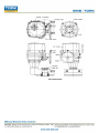
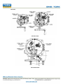
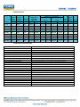
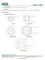
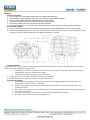
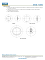
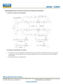
SMS Sanayi Malzemeleri ve Satısı A.S. REA 80-3000 Electric Actuator Manual CONTENTS Check points before using actuator Introduction of REA actuator Setting Location of actuator on the pipeline Electrical wiring Others Precaution before using actuator Troubleshooting Maintenance CHECK POINTS BEFORE USING ACTUATOR Mechanical Check external: Check if drive bushing, painting, handle and lever are OK or not. Compare specification: Compare if specification of the delivered actuator is suitable for your specification of application Check options: Check if all options are correct or not Electrical Check if electrical specification is correct or not (Wiring diagram inside of actuator, name plate). Check if the electrical power is correct or not. Other checking points Check if instruction manual, test report (Warranty papers) and electrical wiring diagram are supplied or not. INTRODUCTION OF REA ACTUATOR Name of Main Parts Externals REA 80-1200 REA 2000-3000 Internals REA 80-1200 REA 2000-3000 PERFORMANCE Nominal Current(A) 60/50Hz Maximum Output Torque Operating Time(s) 60Hz/50Hz Maximum Bore Size Nm 90° mm MODEL Motor Class F Power(W) 60Hz/50Hz 1 Phase 3 Phase 1 Phase 110V 220V REA - 80 80 13/16 Ø20 106/103 NA 1,00/0,97 0,45/0,45 REA - 150 150 21/25 Ø22 185/166 112/216 REA - 200 200 21/25 Ø22 185/166 REA - 300 300 26/31 Ø35 REA - 600 600 26/31 REA - 800 800 REA - 1200 3 Phase 380V 440V NA NA Duty Cycle Manuel Turn Number Weight S4(%) N Kg 70 10 7,4 1,70/1,50 0,84/0,73 0,28/0,37 0,36/0,59 70 11 16,6 112/216 1,70/1,50 0,84/0,73 0,28/0,38 0,36/0,60 70 11 16,6 177/148 130/171 1,67/1,37 0,81/0,68 0,27/0,33 0,34/0,55 70 13,5 22 Ø35 390/410 184/236 3,56/4,27 1,30/1,40 0,42/0,51 0,47/0,66 70 13,5 23 31/37 Ø45 483/389 312/427 4,93/3,59 2,20/1,80 0,61/0,83 0,67/1,10 70 16,5 29 1200 31/37 Ø45 483/389 312/427 4,93/3,59 2,20/1,80 0,61/0,84 0,67/1,10 70 16,5 29 REA - 2000 2000 93/112 Ø65 483/389 312/427 4,93/3,59 2,20/1,80 0,61/0,85 0,67/1,10 70 49,5 75 REA - 3000 3000 93/112 Ø65 483/389 312/427 4,93/3,59 2,20/1,80 0,61/0,85 0,67/1,10 70 49,5 75 STANDARD SPECIFICATION Enclosure Power supply Control power supply Duty cycle(on-off) Duty cycle(modulating) Motor Limit switches Additional limit switches Torque switches Stall protection/operating temp Travel angle Indicator Manual override Self locking Mechanical stopper Space heater Cable entries Lubrication Terminal block Materials Ambient temperature Ambient humidity Anti vibration External coating Weatherproof enclosure IP67, NEMA 4 and 6 110 / 220V AC 1PH, 380 / 440V AC 3PH 50 / 60Hz, 10% 110 / 220V AC 1PH, 50 / 60Hz, 10% S2, 100% Max 30Min S4, 70% Max 300~1600 start/hour Induction motor (Reversible motor) Open / close, SPDT, 250V AC 16A rating Open / close, SPDT, 250V AC 16A rating (except REA80-100) Open / close, SPDT, 250V AC 16A rating (except REA80-100) Built-in thermal protection, open 150°C ± 5°C/ close 97°C± 15°C 90°±10°(0~110°) Continuous position indicator Declutching mechanism Provided by double worm gearing 2 external adjustable screws 10W(110/220V AC) Anti-condensation Three PF3/4 tap (standard type only) Grease moly (EP type) Spring loaded lever push type Steel, Aluminium alloy, AI bronze, Polycarbonate -20 ~+70 (except option electronic board) 90% RH Max.(non-condensing) X Y Z 10g, 0.2~34Hz, 30minute Anodizing treatment before dry powder, Polyester OPTIONAL SPECIFICATION EXA Explosion proof enclosure actuator (Eexd II B T4) REA-series WTA Watertight enclosure actuator (IP68 10M 72HR) REA-series PIU Potentiometer unit (0~1 ) REA-series PCU Proportional control unit (input, output 0~10V DC, 4~20mA DC) REA-series ATS Additional torque switches (SPDT x 2EA 250V AC 10A Rating) except REA-80/100 LCU-B lntegral control (LCU + IMS + phase protect indicator) except REA-80/100 LCU-C Digital display control (LCU + IMS + auto phase discriminator) except REA-80/100 CPT Current position transmitter (output 4~20mA DC) REA-series EXT Extension 120° , 180° , 270° turn RBP Rechargeable battery backup DCM DC motor (24V DC) ADCM Multi AC/DC 24V(integral) except REA-2000, 3000 REA-80/100, 150, 200, 300 REA-80/100, 150, 200, 300 REA-80/100, 150, 200, 300 LPA Lever plate actuator except REA-80/100 SLU Signal lamp unit (white-power on, red-open, green-close, yellow-over torque) FPA1 Fire Proofing Actuator 1050± 5 °C/ 50min FPA2 Fire Proofing Actuator 250± 5 °C/ 150min except REA-80/100 Engineering consult in advance Engineering consult in advance SPECIFICATION Features and structure General: REA series actuator is designed for the 90 degree turn application such as damper , ball, plug, butter fly valve and other equipment Range of torque Min. 80Nm to Max 3000Nm. In between there are 9 models and cater for various torque depending on application. Models are REA-80, 150, 200, 300, 500, 800, 1200, 2000 and 3000. Applicable size of valve Butterfly valve: 50mm (2 ") ~ 600mm (24 ") Ball valve: 40mm (1 1/2 ") ~ 350mm (16 ") Body Material is hard- anodized AL alloy and external coating of epoxy powder is suitable for the severe condition especially against the corrosion. Housing is designed in accordance with standard of ex - proof and IP68 . Sealing Sealing carried out by the O- rings guaranties IP68.(10m under water 10days) Manual Override Just by pulling over the lever, operating mode is switched to manual. And just supplying electrical power to actuator, clutch is automatically disengaged from manual an d operating mode is switched to electric operation . Gear & Self locking 2nd staged Double worm gearing prevents movement caused by back force transfer red from valve and it provides the exact and stable position of actuator and valve when electrical power is off. High efficiency, low noise level and trouble free design are another advantage. Manual hand wheel The Size of hand wheel is designed according to required torque to move the actuator, so that operator can easily move the actuator by hand. Motor Motor specially designed for REA actuator has several features such as high output power, high efficiency and thermostat installed inside of motor prevent overheat of motor and thermal damage of motor coil. Limit switch Since limit switch is directly driven by the 2nd output shaft, position during operation is continuous and accurate. Setting of Cam is so easy and once cam setting is done, position is almost permanent unless operator changes setting again. Torque switch Torque switch driven by the 2nd output drive shaft for continuous and accurate torque detection. Torque spring which detects the variation of torque during operation is installed for preventing damage of valve and actuator under overload condition. Once actuator is under overload, torque switch is tripped and actuator stops immediately. Switches are installed for both open and close direction. This switches set by factory can not be set again without check with factory. Space heater Space heater is installed for preventing damage caused by condensed water inside of actuator and includes thermostat inside to prevent overheating. Temperature of heater can be set as per environmental condition. Stopper bolt Stopper bolt installed both close and open direction prevents actuator’s travel over the limit during manual operation and also protects internal gearing from its breakaway. Indicator Indicator directly driven by 2nd output drive shaft has 4 signal LEDs to show the current operating situation of actuator (Open/Close/Over torque/Power ON- Off). Operator perceives exact current operating situation even from a distance. Terminal block Spring loaded terminal strip is very strong against vibration and to add the number of strip for additional connection is so simple. Wiring Basic wiring is standardized to be simplest and optimal, so that variation depending on electrical specification and options can be so easy and simple. Adaption Mounting base is designed according to ISO5211 but d ifferent dimension depending on application is also possible. Removable dr ive bushing provides convenient machining for adaption. Lubrication Using Greas Moly EP type, no need to refill lubricant for the long time. Others REA guaranty high performance, high quality product throughout various and severe test and inspection. MOUNTING BASE Mounting base (ISO5211 ) REA 80 REA 150-200 REA 300-600 REA 800-1200 REA 200-3000 ACTUATOR DRIVE BUSHING REA 80 REA 150-200 REA 800-1200 REA 300-600 REA 200-3000 SETTING Manual operation a b c d e f Pull over the lever toward hand wheel until lever stands perpendicularly. If lever does not stand perpendicularly, pull over it again turning hand wheel slowly. There is casting mark to indicate rotating direction on hand wheel Clockwise is close direction and counter clockwise is open direction. No need to position the lever to original for electrical operation. Once electrical power is on, the lever automatically return its original position by internal clutch mechanism. Limit switch setting a b Pull over the lever for manual operation and turn hand wheel to move actuator full close (Or open) position. Loose the bolts tightening cam by L- wrench, and turn CLS (or OLS) cam to CW (or to CCW), so that cam may hit the lever of close (or open) limit switch. Then tighten the bolt by L- wrench. Torque switches Torque Switches are set by factory before delivery and therefore no need to set the switches again, but just do as follows for check if switches functions well. a. Push the lever of close switches by screw driver until it sounds "click" then actuator should stop immediately. If it stops, switches work well. b. Check open switches as per just same with above. No guaranty in performance once these switches are set again. Before setting, if it is compulsory, please consult with factory. Stopper bolt setting a. Before manual operation, get both nuts loose which are engaged with stopper bolts and t urn stopper bolt to come out by 3~ 4 threads. b. Move actuator full close position by manual. Once cam hit the lever of limit switch to trip, stop manual operation. c. Then turn close stopper bolt to go forward until it does not go further (end of stopper bolt contacts the 2nd worm wheel). d. Turn close stopper bolt to come out by 2 threads and tighten the loosen nut. e. Do as per same with above for open stopper bolt Indicator setting a. Move actuator full close position and turn indicator by hand until orientation of indicator is aligned to the figure of window. b. Tighten the bolt (Be careful not to be injured by the cutting edge of indicator and leakage of electricity when power is on) c. Figure of Window and indicator REA 80 REA 150-1200 REA 2000-3000 RECOMMENDATION FOR INSTALLATION OF ACTUATOR IN THE PIPELINE Location of actuator on the pipeline Orientation of installation of actuator No limit, but it is recommended to install actuator in the position which cable entry face the ground orientation for water tight function and hand wheel faces front for easy manual operation without interruption. Reserve the space for maintenance. ELECTRICAL WIRING Cable and conduit Cable entries are machined with PF3/4” tap and sealed by Plug before delivery. Please remain the plug as it is if user doesn’t use both cable entries. Please make sure to seal the entries by using rubber or metallic packing after wiring, so that water may not come in. When user use actuator as ex - proof, please make sure to use the certified connection component which is at least same grade with actuator. This is not our scope of supply, but if users don’t use suitable component, factory won’t guaranty the performance of ex - proof actuator. Electrical wiring Check if electrical specification like as power, wiring & etc are correct or not. One sheet of wiring diagram is to be supplied together with actuator. Do the wiring as per the given wiring diagram, such as power, control power, internal wiring and ground. Make sure to supply electric power to heater for keeping inside of actuator clean and dry. Make sure to check wiring to the terminal is strong enough. Make sure that one relay operates one actuator only. Can not operate two or more actuators simultaneously. Make sure to clean inside of actuator and no foreign material inside. Check rotating direction In 3 phase actuator, operator should check the rotating direction of actuator before electrical operation. If operating direction is wrong, limit switches doesn’t function and it results damage from jamming or motor‘s overheating. So, put the actuator at 50% open (or Close) position by manual and supply power into the actuator and check its rotating direction. If actuator moves t open as per open signal, the direction it is OK, but reverse, need to change the wiring. Among 3 of power wires, change 2 wires each other. Then check the rotating direction again in order to confirm it again. Commissioning Make sure to check the rotating direction of actuator first before operation. Check the function of limit and torque switches, direction of indicator, signal LEDs, and space heater. Check l ever movement is OK (Manual over ride) Check the lamps in the control panel. After commission, please make sure to tighten the 4 bolts of the top cover and to do proper sealing. Other Revere direction actuator Generally actuator is set as close for clockwise turning and open for counterclockwise turning. If user want to use reverse direction actuator, please do as follows. REA 80 Open the cover using L - wrench Change wires each other which are connected to terminal no 6 and 7 and do same way for 8 and 9. Change the direction of indicator Put actuator about 50% open position and check rotating direction is correct. REA 150-REA 3000(ON- OFF) Open the cover using L - wrench Change wires each other which are connected to terminal no 6 and 7 and do same way for 8 and 9. Change the direction of indicator (for HQ200 and 300, change window also) Put actuator about 50% open position and check rotating direction is correct. REA 150-REA 3000(Proportional control) Open the cover using L - wrench Change wires each other which are connected to terminal no P1 and P3 in the PCU card Change wires each other which are connected to terminal no 9 and 10 and do same way for 11 and 12. Change the direction of indicator (For REA 2000 and 3000, change the window also) Put actuator about 50% open position and just push the auto setting button. Supply 4 ~ 20mA and check the operation. Potentiometer setting Put actuator full close position and check resistance between P1 (Orange) and P3(Grey), it should be around 1000Ohm. Put the resistance between P1(Orange) and P2(Purple) of potentiometer around 80~ 120Ohm. Engage potentiometer gear with pointer shaft gear and tighten the bolt. Put spring between potentiometer and pointer shaft and fix both. If user wants to use revere direction actuator, change the wires of P1(Orange) and P3(Grey) of PIU each other . Jamming In case that actuator moves wrong direction and moves over the travel limit, internal worm gear contacts the stopper bolt and engaged each other. This is we call, jamming and can not move actuator at all. How to solve a. Off the power b. If jamming is happened during close, take close stopper bolt to come out by c. about 2 ~ 3 threads d. Pull over the lever and put it manual position. e. Turn hand wheel to counterclockwise until 50% open position. f. Check rotating direction again. g. If everything is O.K, put stopper bolt original position. h. If jamming is happened during open, procedure is same with close, but turn hand wheel to clockwise by manual. Special tools for setting L- Wrench 1 set(Metric) Screw drivers - , + ) Spanner set (Metric), Monkey spanner 200mm, 300mm 1 each Wire stripper , Long nose, Light Multi Meter (AC, DC Volt, Resistance) DC signal generator (0~ 4mA DC) : PCU option MA DC Meter (0~ 25mA DC) : PCU and CPT PRECAUTION BEFORE USING ACTUATOR A. Selection of valve and actuator: Review all specification of valve and actuator carefully before making selection and reserve about 30% torque of actuator for safety purpose. If required torque is 90Kg- m, recommended actuator torque is about 117Kg- m. B. Option: Please consult with factory before making selection, if possible. C. Before necessary setting such as limit switch, please don’t operate actuator either fully open or fully close. D. After electrical wiring, make sure to secure the sealing of cable entries. E. Before operating actuator, please review this manual carefully and follow the instruction without fail. Please be careful at temperature, humidity, vibration, voltage drop. F. Storage: Keep actuator dry, clean and cool. G. Trouble: Please refer to following trouble shooting but please don’t dismantle the actuator without consulting with factory. H. If repair or maintenance is required, please check the model, electrical condition, serial Number and current situation to inform factory. Trouble shooting 110/220VAC 1Ph, 380/440VAC 3Ph standard actuator PCU option CPT Option Maintenance Lubrication Lubrication is already done by factory and generally no need to refill it again. But in the places such as very dry condition below R.H 15% or high temperature higher than 30 oC, it is required to do lubr ication once two year through Grease Nipple. Regular operation Electrical power always should be supplied to actuator and it is recommended to operate actuator once a week. Maintenance In order to use actuator for long time, regular maintenance once a year is required. Please check operating condition, corrosion, painting & etc. Others Should you have any further queries, please contact us through Phone, fax and E - mail without hesitation.