1
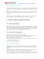
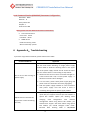
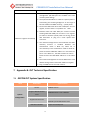
西迪特科技技术有限公司 C‐DATA Technology Co., Ltd. GEPON OLT GEPON OLT FD2000S EPON Optical Fiber Access Head end Equipment 宽带接入 Installation User Manual 用心服务 深圳市西迪特科技有限公司 C-DATA TECHNOLOGY CO.,LTD. Address:Flat 6, Bldg 4,South 2 of Honghualing Industrial Zone, Liuxian Road, Xili Town, Shenzhen, Guangdong, China TEL: +86‐755‐26014509/26014710/26014711 Fax: +86‐755‐26014506 E‐mail: [email protected] Website: www.cdatatec.com FD2000S OLT Installation User Manual Table of Contents 1 PRODUCT INTRODUCTION ‐‐‐‐‐‐‐‐‐‐‐‐‐‐‐‐‐‐‐‐‐‐‐‐‐‐‐‐‐‐‐‐‐‐‐‐‐‐‐‐‐‐‐‐‐‐‐‐‐‐‐‐‐‐‐‐‐‐‐‐‐‐‐‐‐‐‐‐‐‐‐‐‐‐‐‐‐‐‐‐‐‐‐‐‐‐‐‐‐‐‐ 3 1.1 EQUIPMENT BRIEF INTRODUCTION ‐‐‐‐‐‐‐‐‐‐‐‐‐‐‐‐‐‐‐‐‐‐‐‐‐‐‐‐‐‐‐‐‐‐‐‐‐‐‐‐‐‐‐‐‐‐‐‐‐‐‐‐‐‐‐‐‐‐‐‐‐‐‐‐‐‐‐‐‐‐‐‐‐‐‐‐‐‐‐‐‐ 3 1.2 FUNCTIONAL FEATURES ‐‐‐‐‐‐‐‐‐‐‐‐‐‐‐‐‐‐‐‐‐‐‐‐‐‐‐‐‐‐‐‐‐‐‐‐‐‐‐‐‐‐‐‐‐‐‐‐‐‐‐‐‐‐‐‐‐‐‐‐‐‐‐‐‐‐‐‐‐‐‐‐‐‐‐‐‐‐‐‐‐‐‐‐‐‐‐‐‐‐‐‐‐‐ 3 1.3 EQUIPMENT STRUCTURE ‐‐‐‐‐‐‐‐‐‐‐‐‐‐‐‐‐‐‐‐‐‐‐‐‐‐‐‐‐‐‐‐‐‐‐‐‐‐‐‐‐‐‐‐‐‐‐‐‐‐‐‐‐‐‐‐‐‐‐‐‐‐‐‐‐‐‐‐‐‐‐‐‐‐‐‐‐‐‐‐‐‐‐‐‐‐‐‐‐‐‐‐ 4 1.3.1 Introduction of equipment each module ‐‐‐‐‐‐‐‐‐‐‐‐‐‐‐‐‐‐‐‐‐‐‐‐‐‐‐‐‐‐‐‐‐‐‐‐‐‐‐‐‐‐‐‐‐‐‐‐‐‐‐‐‐‐‐‐‐‐‐‐‐‐‐‐ 4 1.3.2 Equipments ‘Component Diagram ‐‐‐‐‐‐‐‐‐‐‐‐‐‐‐‐‐‐‐‐‐‐‐‐‐‐‐‐‐‐‐‐‐‐‐‐‐‐‐‐‐‐‐‐‐‐‐‐‐‐‐‐‐‐‐‐‐‐‐‐‐‐‐‐‐‐‐‐‐‐‐ 5 1.3.3 External Interface ‐‐‐‐‐‐‐‐‐‐‐‐‐‐‐‐‐‐‐‐‐‐‐‐‐‐‐‐‐‐‐‐‐‐‐‐‐‐‐‐‐‐‐‐‐‐‐‐‐‐‐‐‐‐‐‐‐‐‐‐‐‐‐‐‐‐‐‐‐‐‐‐‐‐‐‐‐‐‐‐‐‐‐‐‐‐‐‐‐‐‐‐‐ 5 2 EQUIPMENT INSTALLATION ‐‐‐‐‐‐‐‐‐‐‐‐‐‐‐‐‐‐‐‐‐‐‐‐‐‐‐‐‐‐‐‐‐‐‐‐‐‐‐‐‐‐‐‐‐‐‐‐‐‐‐‐‐‐‐‐‐‐‐‐‐‐‐‐‐‐‐‐‐‐‐‐‐‐‐‐‐‐‐‐‐‐‐‐‐‐‐‐‐‐ 6 2.1 INSTALLATION PREPARATION ‐‐‐‐‐‐‐‐‐‐‐‐‐‐‐‐‐‐‐‐‐‐‐‐‐‐‐‐‐‐‐‐‐‐‐‐‐‐‐‐‐‐‐‐‐‐‐‐‐‐‐‐‐‐‐‐‐‐‐‐‐‐‐‐‐‐‐‐‐‐‐‐‐‐‐‐‐‐‐‐‐‐‐‐‐‐‐‐‐ 6 2.2 OPEN PACKAGE AND CHECKOUT ‐‐‐‐‐‐‐‐‐‐‐‐‐‐‐‐‐‐‐‐‐‐‐‐‐‐‐‐‐‐‐‐‐‐‐‐‐‐‐‐‐‐‐‐‐‐‐‐‐‐‐‐‐‐‐‐‐‐‐‐‐‐‐‐‐‐‐‐‐‐‐‐‐‐‐‐‐‐‐‐‐‐‐‐‐ 7 2.3 INSTALLATION OF EACH MODULE ‐‐‐‐‐‐‐‐‐‐‐‐‐‐‐‐‐‐‐‐‐‐‐‐‐‐‐‐‐‐‐‐‐‐‐‐‐‐‐‐‐‐‐‐‐‐‐‐‐‐‐‐‐‐‐‐‐‐‐‐‐‐‐‐‐‐‐‐‐‐‐‐‐‐‐‐‐‐‐‐‐‐‐ 7 宽带接入 2.3.1 Power supply module Installation ‐‐‐‐‐‐‐‐‐‐‐‐‐‐‐‐‐‐‐‐‐‐‐‐‐‐‐‐‐‐‐‐‐‐‐‐‐‐‐‐‐‐‐‐‐‐‐‐‐‐‐‐‐‐‐‐‐‐‐‐‐‐‐‐‐‐‐‐‐‐‐‐ 7 2.3.2 Installation of Dust filter module ‐‐‐‐‐‐‐‐‐‐‐‐‐‐‐‐‐‐‐‐‐‐‐‐‐‐‐‐‐‐‐‐‐‐‐‐‐‐‐‐‐‐‐‐‐‐‐‐‐‐‐‐‐‐‐‐‐‐‐‐‐‐‐‐‐‐‐‐‐‐‐‐‐ 8 2.3.3 Fan Module Installation ‐‐‐‐‐‐‐‐‐‐‐‐‐‐‐‐‐‐‐‐‐‐‐‐‐‐‐‐‐‐‐‐‐‐‐‐‐‐‐‐‐‐‐‐‐‐‐‐‐‐‐‐‐‐‐‐‐‐‐‐‐‐‐‐‐‐‐‐‐‐‐‐‐‐‐‐‐‐‐‐‐‐‐‐‐ 8 用心服务 2.3.4 PON Card and Switch Control Card Installation ‐‐‐‐‐‐‐‐‐‐‐‐‐‐‐‐‐‐‐‐‐‐‐‐‐‐‐‐‐‐‐‐‐‐‐‐‐‐‐‐‐‐‐‐‐‐‐‐‐‐‐‐‐‐‐ 9 2.3.5 SFP Module Installation ‐‐‐‐‐‐‐‐‐‐‐‐‐‐‐‐‐‐‐‐‐‐‐‐‐‐‐‐‐‐‐‐‐‐‐‐‐‐‐‐‐‐‐‐‐‐‐‐‐‐‐‐‐‐‐‐‐‐‐‐‐‐‐‐‐‐‐‐‐‐‐‐‐‐‐‐‐‐‐‐‐‐‐ 10 2.4 CABLE CONNECTION ‐‐‐‐‐‐‐‐‐‐‐‐‐‐‐‐‐‐‐‐‐‐‐‐‐‐‐‐‐‐‐‐‐‐‐‐‐‐‐‐‐‐‐‐‐‐‐‐‐‐‐‐‐‐‐‐‐‐‐‐‐‐‐‐‐‐‐‐‐‐‐‐‐‐‐‐‐‐‐‐‐‐‐‐‐‐‐‐‐‐‐‐‐‐‐ 10 2.4.1 Uplink SFP Service Port ‐‐‐‐‐‐‐‐‐‐‐‐‐‐‐‐‐‐‐‐‐‐‐‐‐‐‐‐‐‐‐‐‐‐‐‐‐‐‐‐‐‐‐‐‐‐‐‐‐‐‐‐‐‐‐‐‐‐‐‐‐‐‐‐‐‐‐‐‐‐‐‐‐‐‐‐‐‐‐‐‐‐‐‐ 10 2.4.2 PON Port Connection ‐‐‐‐‐‐‐‐‐‐‐‐‐‐‐‐‐‐‐‐‐‐‐‐‐‐‐‐‐‐‐‐‐‐‐‐‐‐‐‐‐‐‐‐‐‐‐‐‐‐‐‐‐‐‐‐‐‐‐‐‐‐‐‐‐‐‐‐‐‐‐‐‐‐‐‐‐‐‐‐‐‐‐‐‐‐ 10 2.4.3 Ground Line Connection ‐‐‐‐‐‐‐‐‐‐‐‐‐‐‐‐‐‐‐‐‐‐‐‐‐‐‐‐‐‐‐‐‐‐‐‐‐‐‐‐‐‐‐‐‐‐‐‐‐‐‐‐‐‐‐‐‐‐‐‐‐‐‐‐‐‐‐‐‐‐‐‐‐‐‐‐‐‐‐‐‐‐ 10 2.4.4 Management Port Connection ‐‐‐‐‐‐‐‐‐‐‐‐‐‐‐‐‐‐‐‐‐‐‐‐‐‐‐‐‐‐‐‐‐‐‐‐‐‐‐‐‐‐‐‐‐‐‐‐‐‐‐‐‐‐‐‐‐‐‐‐‐‐‐‐‐‐‐‐‐‐‐‐‐‐ 11 3 OLT POWER SUPPLY AND WORKING STATUS CHECKOUT ‐‐‐‐‐‐‐‐‐‐‐‐‐‐‐‐‐‐‐‐‐‐‐‐‐‐‐‐‐‐‐‐‐‐‐‐‐‐‐‐‐‐‐‐‐‐‐‐‐‐ 11 3.1 CHECK OUT POWER SUPPLY ‐‐‐‐‐‐‐‐‐‐‐‐‐‐‐‐‐‐‐‐‐‐‐‐‐‐‐‐‐‐‐‐‐‐‐‐‐‐‐‐‐‐‐‐‐‐‐‐‐‐‐‐‐‐‐‐‐‐‐‐‐‐‐‐‐‐‐‐‐‐‐‐‐‐‐‐‐‐‐‐‐‐‐‐‐‐‐‐ 11 3.2 CHECK OUT OLT’S WORKING STATUS ‐‐‐‐‐‐‐‐‐‐‐‐‐‐‐‐‐‐‐‐‐‐‐‐‐‐‐‐‐‐‐‐‐‐‐‐‐‐‐‐‐‐‐‐‐‐‐‐‐‐‐‐‐‐‐‐‐‐‐‐‐‐‐‐‐‐‐‐‐‐‐‐‐‐‐‐‐ 11 3.2.1 Check out ONU Registration ‐‐‐‐‐‐‐‐‐‐‐‐‐‐‐‐‐‐‐‐‐‐‐‐‐‐‐‐‐‐‐‐‐‐‐‐‐‐‐‐‐‐‐‐‐‐‐‐‐‐‐‐‐‐‐‐‐‐‐‐‐‐‐‐‐‐‐‐‐‐‐‐‐‐‐‐‐ 11 3.2.2 Network Connection Checkout ‐‐‐‐‐‐‐‐‐‐‐‐‐‐‐‐‐‐‐‐‐‐‐‐‐‐‐‐‐‐‐‐‐‐‐‐‐‐‐‐‐‐‐‐‐‐‐‐‐‐‐‐‐‐‐‐‐‐‐‐‐‐‐‐‐‐‐‐‐‐‐‐‐‐ 12 3.2.3 Network Management Checkout ‐‐‐‐‐‐‐‐‐‐‐‐‐‐‐‐‐‐‐‐‐‐‐‐‐‐‐‐‐‐‐‐‐‐‐‐‐‐‐‐‐‐‐‐‐‐‐‐‐‐‐‐‐‐‐‐‐‐‐‐‐‐‐‐‐‐‐‐‐‐‐ 12 4 DAILY MAINTENANCE ‐‐‐‐‐‐‐‐‐‐‐‐‐‐‐‐‐‐‐‐‐‐‐‐‐‐‐‐‐‐‐‐‐‐‐‐‐‐‐‐‐‐‐‐‐‐‐‐‐‐‐‐‐‐‐‐‐‐‐‐‐‐‐‐‐‐‐‐‐‐‐‐‐‐‐‐‐‐‐‐‐‐‐‐‐‐‐‐‐‐‐‐‐‐‐ 12 5 DEFAULT CONFIGURATION ‐‐‐‐‐‐‐‐‐‐‐‐‐‐‐‐‐‐‐‐‐‐‐‐‐‐‐‐‐‐‐‐‐‐‐‐‐‐‐‐‐‐‐‐‐‐‐‐‐‐‐‐‐‐‐‐‐‐‐‐‐‐‐‐‐‐‐‐‐‐‐‐‐‐‐‐‐‐‐‐‐‐‐‐‐‐‐‐‐ 13 6 APPENDIX A:TROUBLESHOOTING ‐‐‐‐‐‐‐‐‐‐‐‐‐‐‐‐‐‐‐‐‐‐‐‐‐‐‐‐‐‐‐‐‐‐‐‐‐‐‐‐‐‐‐‐‐‐‐‐‐‐‐‐‐‐‐‐‐‐‐‐‐‐‐‐‐‐‐‐‐‐‐‐‐‐‐‐‐ 14 7 APPENDIX B: OLT TECHNICAL SPECIFICATION‐‐‐‐‐‐‐‐‐‐‐‐‐‐‐‐‐‐‐‐‐‐‐‐‐‐‐‐‐‐‐‐‐‐‐‐‐‐‐‐‐‐‐‐‐‐‐‐‐‐‐‐‐‐‐‐‐‐‐‐‐‐‐‐‐ 16 8 7.1 GEPON OLT SYSTEM SPECIFICATION ‐‐‐‐‐‐‐‐‐‐‐‐‐‐‐‐‐‐‐‐‐‐‐‐‐‐‐‐‐‐‐‐‐‐‐‐‐‐‐‐‐‐‐‐‐‐‐‐‐‐‐‐‐‐‐‐‐‐‐‐‐‐‐‐‐‐‐‐‐‐‐‐‐‐‐‐ 16 7.2 FD2000C CHASSIS SPECIFICATION ‐‐‐‐‐‐‐‐‐‐‐‐‐‐‐‐‐‐‐‐‐‐‐‐‐‐‐‐‐‐‐‐‐‐‐‐‐‐‐‐‐‐‐‐‐‐‐‐‐‐‐‐‐‐‐‐‐‐‐‐‐‐‐‐‐‐‐‐‐‐‐‐‐‐‐‐‐‐‐ 18 7.3 FD2000M SWITCH CONTROL SPECIFICATION ‐‐‐‐‐‐‐‐‐‐‐‐‐‐‐‐‐‐‐‐‐‐‐‐‐‐‐‐‐‐‐‐‐‐‐‐‐‐‐‐‐‐‐‐‐‐‐‐‐‐‐‐‐‐‐‐‐‐‐‐‐‐‐‐‐‐‐ 18 7.4 FD2102T PON SERVICE CARD SPECIFICATION ‐‐‐‐‐‐‐‐‐‐‐‐‐‐‐‐‐‐‐‐‐‐‐‐‐‐‐‐‐‐‐‐‐‐‐‐‐‐‐‐‐‐‐‐‐‐‐‐‐‐‐‐‐‐‐‐‐‐‐‐‐‐‐‐‐‐ 19 ENDING ‐‐‐‐‐‐‐‐‐‐‐‐‐‐‐‐‐‐‐‐‐‐‐‐‐‐‐‐‐‐‐‐‐‐‐‐‐‐‐‐‐‐‐‐‐‐‐‐‐‐‐‐‐‐‐‐‐‐‐‐‐‐‐‐‐‐‐‐‐‐‐‐‐‐‐‐‐‐‐‐‐‐‐‐‐‐‐‐‐‐‐‐‐‐‐‐‐‐‐‐‐‐‐‐‐‐‐‐‐‐‐‐‐ 20 2 FD2000S OLT Installation User Manual 1 Product Introduction 1.1 Equipment Brief Introduction EPON OLT GEPON OLT FD2000S is EPON system head‐end equipment. It adopted the concept of modular design, combined with the advanced industrial design and manufacturing technology, providing highly reliable, flexible, easy for maintenance broadband access products to users. EPON OLT GEPON OLT FD2000S use 2U standard chassis, having 8 gigabit SFP port, supported electrical module and optical module. Service slot support 4 PON panels at most, the whole chassis could support 16 PON ports at most. It can connected 512 remote ONU maximally (by1:32 splitter) and1024 remote ONU mostly(by 1:64 splitter). EPON OLT GEPON OLT FD2000S OLT Equipment fully compliant with IEEE802.3ah standard, meeting the demands of China telecom EPON equipment’s interconnection. and it can support hybrid networking with third‐party ONU. OLT GEPON OLT FD2000S fully compatible with C‐Data’s whole ONU equipment. Through switching in different ONU equipment, users can use FDF2000S EPON system to build various access networking, such as FTTH,FTTB and fiber to HFC network, Providing high‐speed broadband access and IP integrated service. 宽带接入 用心服务 1.2 Functional Features Support 16 PON ports at most. Support connected 1024 remote ONU(by 1:64 splitter). Support 8 uplink PON ports. Layer‐two link rate switch. MAC Address Capacity:4K VLAN supported number:4096 ONU auto‐detection and registration support plug and play. Dynamic bandwidth allocation. Support online upgrading and ONU batch upgrade. Management Interface: Support in‐band and out‐band management. Management Mode: CLI, Remote TELNET,EMS Centralized Management by means of OAM protocol. Reliability: dual power redundant power supply, power supply and fan module real‐time monitoring, fault warning 3 FD2000S OLT Installation User Manual 1.3 Equipment Structure GEPON OLT FD2000S OLT external View ※Equipment Color and Appearance details are based on shipping date and order requirement. 1.3.1 Introduction of equipment each module Equipment is composed by the following parts: Equipment Chassis Chassis Model NO.:FD2000C 2U,19 inch OLT chassis. You can install it in 19’’ standard equipment cabinet. The size of chassis complies with GB/T 3047.4 standard (...)and GB/T3047.8(...). 宽带接入 用心服务 Power Supply Module Power supply module is the power supply unit for chassis.FD2000C chassis provides 2 power supply slot, could install 2 power supply module. It support hot plug function, divided 220/110V AC and 48V DC power module. Fan Module FD2000C chassis configured a group of 4 fans for heat dissipation, and it support hot plug function. Dust‐filter Module FD2000C chassis is installed with a dust filter module for filter the dust that suction casing in the air. Support hot plug function, available for washing. Switch Control Module Support Model NO.:FD2000M Switch control module is the necessary module for OLT GEPON OLT FD2000S equipment. It used to communicate with the PON port service, functioned as Ethernet interface’s data switch and management control function of whole chassis’s. Switch control module installs in NMS slot of FD2000C chassis, supporting hot pluggable. PON SFP Installation on Model NO.: FD2102T, FD2104T PON SFP used to access the EPON ONU equipment, deliver the uplink and downlink 4 FD2000S OLT Installation User Manual data transmission to uplink Ethernet port. FD2012T PON card has two‐port PON SFP slots, and FD2014T has four‐ports PON SFP slots. PON SFP is installed in the 1~4 PON card slot of FD2000C chassis, supporting hot plug. Uplink SFP Uplink SFP is the optional part. Switch control module’s SFP is installed just according to the requirements of networking; you could choose 1000BASE‐T electrical module or 1000BASE‐LX optical module. PON SFP’s slot should be installed with 1000BASE‐PX20 EPON OLT SFP. 1.3.2 Equipments ‘Component Diagram Power Module Supply 宽带接入 用心服务 Dust Filter Module Fan Group Module Wiring Rack Switch control card PON Card Diagram 1 Whole equipment structure diagram 1.3.3 External Interface Uplink port Slot Uplink slot is used for connection with uplink device. There are 8 uplink slots, which could install electric 10/100/100M SFP or 1.25G optical SFP.Please see the diagram as follows 5 FD20 000S OLTT Installattion User Manual Diagram 2 2 Uplink Slot Diagram GEP PON OLT FD D2000S chasssis providees 8 gigabit uplink portts. Physical Interface tyype is SFP S slot. Every E portt could bee configure ed as eleectrical po ort or optical portt(through software s co onfiguration n).The defaault configu uration is shipped with w elecctrical SFP . Uplink po ort supportts port trun nk manageement. Thro ough the port p trun nk, whole equipment e s support 8G G uplink ban ndwidth at most. Each h uplink port p is 1.25 1 gigabitt (except special s con nfiguration),, users cou uld choose one port or mutti‐ports to connect the uplinkk device based b on the actuaal networkking dep ployment. Port Manaagement Network manaagement port is used fo or the network manageement for u users. This p port is in n switch con ntrol modulee. Please seee the diagrram as follow ws: 宽带 带接入 入 用 服务 用心服 D Diagram 3 M anagement P Port Diagram PON OLT FD D2000S pro ovide 1 10M M Ethernet out‐band managemeent port, 1 CLI GEP man nagement port, used for managging the OLT O and ON NU equipm ment. Besid des speccified manaagement po ort, every uplink u port could use as in‐band management portt, no need sspecial conffiguration(eexcept VLAN N Management). PON Port PON N port used d to connecct networking between ONU and d ODN, Phyysical Interfaace typee is SFP, port standard d is 1000BASE‐PX20. W When you w want to use it, you should install OLT mod dule. And it can conneccted 64 ONU U for every port. 2 Equipment Instaallation 2.1 Installation Prep paration Cheeck out Instaallation envvironment In normal co onditions, OLLT GEPON OLLT FD2000S e equipment in nstall in the 1 19 inch stand dard equipment ccabinet. If there is no suittable equipm ment cabinet, you can instaall it in the fixed flat surface. Equipment LLoading Capaacity in flat su urface should be larger tthan 20KG. Around the equipment, eespecially thee two sides air‐vent of equ uipment shou uld leave 10ccm’s 6 FD2000S OLT Installation User Manual space for ventilation. Environment temperature range of equipment is ‐5℃~+45℃;Relative humidity is 10%~90%. And the place of equipment should keep clean. Check out power supply and ground connection Before the installation, you should check out if the power supply meet the demands of equipment.OLT GEPON OLT FD2000S have AC and DC two kinds of power‐supply modes. AC power supply’s voltage is 220V, DC power supply’s voltage is 48V. Please check if the condition of installation environment in line with the power supply’s specification. For better working about equipment, it is necessary for good ground connection when install the equipment. Good ground connection is the guarantee of anti‐lightning and anti‐interference. Check out Supporting Facilities 宽带接入 Before the installation of equipment, you should check out if the uplink device is ready and if OLT GEPON OLT FD2000S’s uplink port module in line with uplink equipment’s port. If you choose optical module of uplink port, you should check if it is conform to optical fiber splice. 用心服务 2.2 Open package and checkout According to the packing list or supply contract, check the model NO and quantity of equipment in line with the purchase order. When you inspect the equipment, please take out the equipments carefully and slightly . If there is no protection of anti‐static, avoid touching the PCB board or other electronic parts. If you found the case of damaged equipment, wrong or missing delivery, please contact the supplier for confirmation.. 2.3 Installation of Each Module 2.3.1 Power supply module Installation Please take out the power supply module and push into the chassis, and tightened the screws then fixed the power supply module on the frame. Please see the diagram as follows: 7 FD2000S OLT Installation User Manual Power supply module Diagram 4 Power Supply Module Installation Diagram 2.3.2 Installation of Dust filter module 宽带接入 The parts of Dust filter module will install with equipment in the factory, no need users to install again. After you change new one or remove to clean, you need to install by yourself. Dust filter module installed in the back on the right‐side of chassis, when you install, push it to the chassis gently along the guide rail than fixed by screws. Please see the diagram below: 用心服务 Dust Filter Module Diagram 5 Dust filter module Installation Diagram Dust filters module need to clean once per 1‐3 months. When cleaning, taking down the dust filter module and rinsing it directly, than dry out for next time use. 2.3.3 Fan Module Installation Fan module parts will is installed in OLT chassis in the factory, no need to install again. After you change new one or plug out to clean, you need to install by yourself. Fan modules installed in the back on the right‐side of chassis. When you install, push it into the chassis gently along the guide rail then fixed with screws. Please see the diagram below: 8 FD2000S OLT Installation User Manual Fan Module Diagram 6 Fan Module Installation Diagram 2.3.4 PON Card and Switch Control Card Installation 宽带接入 OLT GEPON OLT FD2000S equipment has two kinds of Card, PON Card and Switch Control Card. The PON card and switch control card have been installed in OLT chassis during production process .There is no need to install PON card or switch control card upon the receipt of parcels. Switch control card is installed in the upper side marked as “NMS” slot,.PON card is installed under the switch control card marked as “1” ~ “4” PON port slot. There is no difference among these four PON port card slots,. Users can install the PON port card to one or more slot if needed. Installation steps as follows: 1)Hold the card and push into the chassis gently along the guide rail. 用心服务 2)With the help of panel handle, push the cards into the chassis completely. Now the cards panel will be parallel and level with the front panel of chassis. 3) Fix the cards on the chassis with screws. Please see the installation diagram of PON card and Switch control card: Switch control card Card PON PON Card Diagram 7 PON card and Switch control card Installation 9 FD2000S OLT Installation User Manual 2.3.5 SFP Module Installation OLT GEPON OLT FD2000S equipment’s switch control card uplink port and PON card’s port are SFP ports. SFP port is the standard interface for the common telecommunication equipment. When you want to install it, bring the right SFP module and insert to the relevant SFP slot directly. Remark: 10/100/1000M Ethernet SFP is installed in uplink slots of switch control card when the uplink device connection with OLT is UTP cable. 1.25G 1310nm (or 1550nm) dual fiber SFP is installed in the uplink slots of switch control card when the uplink device connection with OLT is fiber. 1310nm/1490nm, 1.25G, 20KM SFP is OLT PON SFP, which is installed in the PON card slot . 宽带接入 2.4 Cable Connection 用心服务 2.4.1 Uplink SFP Service Port Based on your networking requirements, switch control card’s uplink SFP port can be configured as electrical module or optical module. When the uplink input is UTP cable, please connect uplink Ethernet SFP on olt switch control card. When the uplink input is fiber, please connect uplink optical SFP on OLT switch control card . 2.4.2 PON Port Connection PON service card slots installs standard 1000BASE‐PX20 OLT SFP .The OLT SFP interface is SC/PC .Please use the patch cord with SC/PC connector to connect between the OLT and the ODN networking . 2.4.3 Ground Line Connection Ensure the safety and reliable working of equipment, OLT GEPON OLT FD2000S equipment should be connected with the ground if necessary. Grounding screws are located in the right back side of chassis. When connecting, you should use screwdriver to loosen the grounding screw first, then connect the ground cable, finally tighten the screws. 10 FD2000S OLT Installation User Manual 2.4.4 Management Port Connection OLT GEPON OLT FD2000S equipment provides CLI management interface (marked as “CONSOLE” RJ45 type port) and out‐band management internet access (marked as “MANAGE” RJ45 type port). Before starting the CONSOLE port management, please use the serial cable's RJ45 port to connect the console port on OLT and the other end of DB9 port of serial cable to PC's serial console port. When starting the out‐band management, please use straight and cross Ethernet cable, connecting “MANAGE” out‐band management interface to network or managed PC. 3 OLT power supply and working status checkout 宽带接入 3.1 Check out power supply 用心服务 Before you connect the power supply, double check the power supply if it is accord with the power supply requirements. If each module and card are installed correctly . If the equipment is in reliable grounding or not. After checking everything is OK, you can turn on the power switch of power supply module. 3.2 Check out OLT’s working status Please check if the OLT’s working status from following aspects : Check the power LED. The power LED will be on, if the power supply module is turned on. If four fan module working status LED is on, it means all fan functions well. “CRI” and “MAJ” alarm LED should be off. If the uplink equipment is connected correctly with uplink interface on switch control card, the relevant connection LED is on. “PWR” LED on PON Card should be on 3.2.1 Check out ONU Registration In default situation, there is no need any configuration after you turn on the equipment . ONU equipment can be registered after connected with the PON port of OLT GEPON OLT FD2000S. Before starting access the equipment, please use optical power meter to measure the optical power of PON port, and check if it’s in equipment specification range. Using one ONU equipment correctly connecting with any PON port of OLT. check if this ONU can be registered to OLT by means of the ONU’s LED working status , once the ONU 11 FD2000S OLT Installation User Manual is successfully registered, the “LNK” LED close to PON port of OLT should be on . 3.2.2 Network Connection Checkout In the case of default configuration, the network of users could communicate with GEPON OLT FD2000S \ when ONU registers with GEPON OLT GEPON OLT FD2000S. Connect a PC with an ONU UNI port and check if the network is running well by means of ping LAN (in the same IP address) or by PING package tools. 3.2.3 Network Management Checkout Local Command Line Management Use the RJ45/DB9 Serial Port cable (in package) to link management PC with GEPON OLT FD2000S local equipment command line port (CONSOLE PORT). Management computer can access to OLT equipment from Super terminal interface of the PC for configuration.. 宽带接入 用心服务 In Band and out band Management Use PC which has installed C‐Data’s EMS network management software to connect in band or out band port of GEPON OLT GEPON OLT FD2000S. EMS network management can visit GEPON OLT GEPON OLT FD2000S after adding the olt into EMS interface. The icon of GEPON OLT GEPON OLT FD2000S shows green, and its PON service card is also green. Icon of ONU which register to GEPON OLT GEPON OLT FD2000S is green under EMS interface as well. ※Please refer to relevant CLI user manual if you want to know more about command management and EMS network management configuration user manual to know more about EMS network management functions and operations 4 Daily Maintenance Please pay attention to the following key points when using GEPON OLT GEPON OLT FD2000S Monitoring Equipment Alarm There should be a server when using GEPON OLT FD2000S. This server should install C‐Data’s EMS network management software. IP alarm address of GEPON OLT FD2000S should be the same as management server’s IP address segment. To receive the ONU operation alarm information and process the following key alarms on time: Off alarm. In order to increase reliability of system power supply, we recommend you turn on double power supply. When one power supply is out of working, you should find out the reason and change it on time. Fan abnormal alarm. GEPON OLT FD2000S uses fan module which has 4 fans to loss heat. 12 FD2000S OLT Installation User Manual GEPON OLT should works under specified range of working temperature and humidity. There is no influence if there is one fan out of work, but you should find out the reason and replace it on time if there are two or more fans stop working. Network management software EMS can’t be logged in. You should solve it out on time. Network management software EMS display that PON Service Card which is installed can’t be detected. You should solve it on time. Dust Handle Ventilation environment is good for heat dissipation of GEPON OLT. You should check if the dust‐proof has too much dust. If so, you should clean it. Otherwise the heat loss problem will influence the lifetime of GEPON OLT. 5 Default Configuration 宽带接入 The factory setting of GEPON OLT is as follows. Up‐link Port Configuration 用心服务 There are eight uplink ports on switch control card. These ports’ factory setting is under Ethernet port mode. Under this mode, you can only use Ethernet Copper SFP on uplink slots of OLT. Ethernet port mode and Optical port mode can be changed via EMS network management software configuration. Eight uplink ports’ default settings could be changed via EMS or CLI if necessary. All data retransmission of uplink ports and PON ports are based on layer two switches. PON Port Configuration All default factory settings of the PON port are enabled. Any PON port can be disabled by network management software. Network Parameter Configuration Out Band Network Port (uplink port on switch control card) IP Address: 192.168.120.100 Subnet Mask: 255.255.255.0 Default Gateway: 192.168.120.1 Read community: public Write Community: private In Band Network Port IP Address: 192.168.1.100 Subnet Mask: 255.255.255.0 Default Gateway: 192.168.1.1 Read community: public Write Community: private 13 FD2000S OLT Installation User Manual Local Command Line Port(CONSOLE) Parameter Configuration Band Rate: 9600 Data Bit: 8 Parity Check: NO Stop Bit: 1 Flow Control: NO Management Interface Default Username and Password Local Command Line Username:admin Password:admin SNMP Access Read Community: public Write Community: private 宽带接入 用心服务 6 Appendix A:Troubleshooting If you have any problem as follows, please reference this table. Common Problems Approach GEPON OLT can work with double power supply module. It can also work when switching on single power supply module. PWR ‘A’ shows the working status in the upper slot of the power supply module and ‘B’ shows the lower slot one. Please check it out according to steps below: LED is not on after turning on power supply 1) Observe if fans work or if there is another LED light on. If fans and all LED is off, it means power supply is abnormal or Power LED is damaged. 2) If it can’t work, please check power supply plug and power cord. You should also check if it plug tightly. 3) Take two power supply modules to cross connection with power supply cord and check if there is something wrong with the power supply module. Uplink SFP can’t link with OLT equipment or work something anomaly 1) Check out uplink port working mode. GEPON OLT uplink SFP port support electrical port SFP module or optical SFP module. Uplink port working mode changing need configuration with network management. When using electric SFP module, you should insert ‘Copper’ SFP mode. When using optical SFP module, you should configure ‘Fiber’ mode. Ethernet SFP's working mode is 100/1000M 14 FD2000S OLT Installation User Manual auto‐negotiable when the uplink port working mode is "Copper" under EMS interface. 2) Check if net wire has quality problem, RJ45 connector has bad connection or net wire is more than 100 meters. 3) Check if uplink port works. 4) Check if SFP is plugged in the right way. If it doesn’t work, please plug it out and insert for several times. 1) Working mode of SFP port is ‘Fiber’.(PS:factory default setting is ‘Copper’ mode) 2) Check if optical module matches with its parameter. Such as SM/MM or wave length. When using uplink SFP optical module, the link fails or work abnormally 宽带接入 3) Please check the both end's link power budget belongs to the range of the OLT and ONU SFP's receiving power. Whether it's saturation optical power; whether it’s receiving sensitivity Check if patch cord bending excessively. 用心服务 4) Check if port connector is correct, patch cord connector and module interface contacts well. 5) Check optical connector is clean 1) Check if using right connecting RJ45/DB9 serial cable (in package). CONSOLE Port can’t connect successfully MANAGE PORT can’t work 2) Check PC bandwidth rate is the same with GEPON OLT setting(factory fault setting band rate is 9600bit/s); 3) If you use PC USB to connect by DB9/USB, please check whether driving install correctly. 1) OLT GEPON OLT's management port is fixed at 10M full‐duplex working mode .Please check the uplink device working mode is match with OLT uplink port's working mode. (Generally speaking, the connected uplink device port could be configured as auto negotiation or fixed 10M full‐duplex working mode .100M working mode is not recommended.) 2) Check if net wire is OK Power Supply LED of PON 1) Check if chassis has installed power supply module or Service Card is l off not 2) Check if PON Service Card is plugged tightly. 3) Change it to another slot. ‘LNK’ of PON Service Card is off In the case of normal working, ‘LNK’ LED light on when ONU register successfully. If it light off, please check it out by following steps. 1) If this olt equipment works. Usually it will take 40 seconds to start working after turning on . 2) If there is ONU which is registered under this port. 15 FD2000S OLT Installation User Manual (can watch ONU register LED) 1) Check PON port working status through network management. (All PON ports are enabled in the case of factory fault setting). 2) Use Optical Power Meter to observe if optical power’s transmitting and receiving budget are in the range of OLT SFP module and ONU receiving optical power. 3) Connect the ONU with other card or PON port. If it can register, it means there is no problem for ONU. 4) Subtract other link under PON port. Connect normal working ONU with PON port and see if it can register (In order to avoid the optical power too strong, please add attenuator or plug out a little optical fiber ONU can’t register successfully connector. 宽带接入 5) Use network management to check whether the ONU authority function is enabled. Whether the authorization mode is Black list, white list or non‐authority? If the authorization mode is black list, please check the ONU Mac address is in the black list. (If it's in the black list , the ONU couldn't be online.) Please check if the ONU MAC address is in the white list . 用心服务 6) Use network management to resume PON service card default setting. Restart and watch if ONU can register. 7) Plug out PON Service Card and restart it. 7 Appendix B: OLT Technical Specification 7.1 GEPON OLT System Specification Item Parameter Specification Chassis FD2000C Chassis Support Switch Control FD2000M Switch Control Module System Card Configuration FD2102T 2 ports PON Service Card Support Service Card FD2104T 4 ports PON Service Card PON Ports Number Support 2~16 PON ports 16 FD2000S OLT Installation User Manual Network Management Mode Support SNMP, TELNET, local network management Network Switch Control Card, PON Service Card, Management Network Management accessing ONU , chassis power supply, fan Object module Equipment Size: 2U 19inch standard chassis Dimension Depth: 470mm Physical Package size: 610mm×580mm×180mm Specification Empty Chassis Weight: 15.5kg Weight Full loaded weight: 19.5kg 宽带接入 All control card, power supply modules, fan Hot‐plug Performance module and dust‐proof Support hot‐plug 用心服务 Specification Minimum configuration consumption: 38w Power Consumption Full loaded consumption: 85w Working Temperature: 0~50℃ Working Temperature Environment Storage Temperature: ‐40~85℃ Environment Humidity Environment 5%~95%, non‐condensing Input Voltage Excursion 85VAC~264VAC Input Frequency 47~63Hz 220VAC Power Input Currency <2.0A Working Efficiency >84% Output Voltage 48VDC Maximum Power 153W Module Specification ‐48VDC Power Supply Input Voltage Range 36~75VDC Specification 17 FD2000S OLT Installation User Manual 7.2 FD2000C Chassis Specification Item Parameter Specification One FD2000M Switch Control Card (essential) Support Control Card Four FD2102T or FD2104T PON Service Cards (one to four pieces can be chosen) Function Power Supply Specification Configuration Two power slots, ex‐work packing: double 220V AC power supply module , 220VAC or ‐48VDC power supply module can be chosen Fan 1 fan module( include 4 fans), standard configuration One Anti‐dust filter mesh module, standard Anti‐dust Filter Mesh 宽带接入 configuration 480mm×470mm×87mm 用心服务 Dimension Physical properties Weight Chassis Weight:15.5kg 7.3 FD2000M Switch Control Specification Item Parameter Specification Quantity: 8 Physical Interface: SFP Slots Uplink Port Interface Types:10/100/1000BASE‐T ,1000BASE‐SX or 1000BASE‐LX Interface Specification Out Band Management One 10BASE‐T out band network port Port Local Console Port One local CONSOLE management port One power supply LED Eight uplink working status LED LED One network management working status LED LED Four fan working status LED Alarm LED Function Two alarm LED Switch Function Two‐layer convergence switch 18 FD2000S OLT Installation User Manual Specification MAC Address Capacity: 16K Support Port VLAN, Protocol VLAN Support QINQ Supported Function Support 802.3ad TRUNK Protocol Support RSTP rapid spanning tree Support IGMP Proxy Support 802.1x flow control Port status, configuration management Support VLAN,TRUNK,RSTP,IGMP and so on PON Service Card configuration and management Management Function 宽带接入 online ONU configuration and management User management 用心服务 Alarm management 7.4 FD2102T PON Service Card Specification Item Parameter Specification Quantity: 2 PON Port Physical Interface: SFP insert Type of port: 1000BASE‐PX20 Maximum splitting ratio: 1: 64 Transmission distance : 20KM Port Specification Port speed: Symmetrical 1.25Gbps PON Optical Port Specification Wave length: transmission 1490nm, receiving 1310nm Emission optical power: +2~+7dBm Receiving sensitivity: ‐27dBm Maximum saturated power: ‐6dBm One power supply LED LED LED Two PON port working status LED Functional Functional Specification 19 Comply with IEEE802.3ah EPON protocol FD2000S OLT Installation User Manual Specification Support data encryption Support dynamic bandwidth allocation Support OAM and OAM Support ONU certification Support dynamic distance measurement Support ACL Support QOS, Service stream classification and marker Support RSTP,IGMP Proxy Physical Dimension Specification Weight 宽带接入 145mm(L)×253mm(H)×24mm(W) 0.7kg 用心服务 8 Ending Thanks very much for deploying C‐DATA GEPON OLT equipment. Should have any doubt or problem to know about our products installation, please don’t hesitate to contact us. C‐DATA Technology Co.,Ltd. Address:Flat 6, Bldg 4,South 2 of Honghualing Industrial Zone, Liuxian Road, Xili Town, Shenzhen, Guangdong, China TEL: +86‐755‐26014509/26014710/26014711 Fax: +86‐755‐26014506 E‐mail: [email protected] Website: www.cdatatec.com 20