1
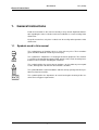
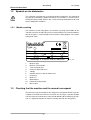
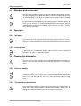
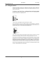
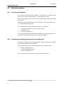
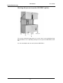
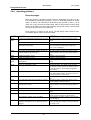
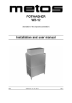
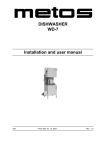
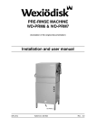
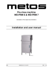
HOOD TYPE DISHWASHER
WD-7 DUPLUS
(translation of the original documentation)
Installation and user manual
S/N: (En)
Valid from: 201403
Rev.:
WD-7 DUPLUS
Rev. (201403)
1. General instructions ........................................................................ 1
1.1 Symbols used in this manual ...........................................................................
1.2 Symbols on the dishwasher .............................................................................
1.2.1 Machine marking ......................................................................................
1.3 Checking that the machine and the manual correspond ..................................
1
2
2
2
2. Safety instructions ........................................................................... 3
2.1 General information .........................................................................................
2.2 Transport ..........................................................................................................
2.3 Installation ........................................................................................................
2.4 Detergent and drying agent .............................................................................
2.5 Operation .........................................................................................................
2.5.1 Hot water ..................................................................................................
2.5.2 Crushing risk .............................................................................................
2.6 Cleaning the dishwasher ..................................................................................
2.6.1 Pressure washing .....................................................................................
2.6.2 The outside of the machine ......................................................................
2.7 Washing the floor .............................................................................................
2.8 Repairing and servicing the dishwasher ..........................................................
2.9 Recycling the machine .....................................................................................
3
3
3
4
4
4
4
4
4
4
5
5
5
3. Installation ........................................................................................ 6
3.1 General information .........................................................................................
3.2 Requirements for the installation site ...............................................................
3.2.1 Lighting .....................................................................................................
3.2.2 Ventilation .................................................................................................
3.2.3 Drain .........................................................................................................
3.2.4 Space for servicing ...................................................................................
3.3 Transport and storage ......................................................................................
3.3.1 Unpacking .................................................................................................
3.3.2 Recycling the packaging ...........................................................................
3.4 Installation ........................................................................................................
3.4.1 Positioning the machine ............................................................................
3.4.2 Installing auxiliary equipment ....................................................................
6
6
6
6
6
7
7
7
7
8
8
9
WD-7 DUPLUS
Rev. (201403)
3.5 Connections ................................................................................................... 12
3.5.1 Electrical connection ............................................................................... 13
3.5.2 Water connection, regardless of any options .......................................... 13
3.5.3 Drain connection, machines without a drain pump ................................ 14
3.5.4 Drain connection, machines with a drain pump ...................................... 14
3.5.5 Detergent and drying agent connection .................................................. 15
3.5.6 Bleeding the hood lifting cylinder (option) ............................................... 16
3.5.7 Steam hood with extractor (option) ........................................................ 17
3.5.8 Condensation unit with heat recovery through the condensing battery
(option) ............................................................................................................. 18
3.6 Settings options for detergent and drying agent equipment
(option) ................................................................................................................. 20
3.6.1 24V AC or 230V AC power supply for detergent and drying agent dosing via
relay 9/J71 and relay 11/J73 ............................................................................ 20
3.6.2 Settings options for relay 9/J71 .............................................................. 23
3.6.3 Settings options for relay 11/J73 ............................................................ 24
3.7 Trial operation ................................................................................................ 25
3.7.1 Start-up schedule .................................................................................... 25
3.8 Technical documentation ............................................................................... 27
4. Instructions for use ........................................................................ 28
4.1 Preparations ...................................................................................................
4.1.1 The machine's design .............................................................................
4.1.2 Preparations before filling .......................................................................
4.1.3 Filling the machine ..................................................................................
4.2 Using the machine .........................................................................................
4.2.1 Selecting a programme ...........................................................................
4.2.2 Changing the washing temperature and washing time ...........................
4.2.3 Washing ..................................................................................................
4.3 After use – cleaning .......................................................................................
4.3.1 Draining and internal cleaning (machine without a drain pump) .............
4.3.2 Draining and internal cleaning (machine with a drain pump) ..................
4.3.3 Emptying the tank for the recirculating rinse ...........................................
4.3.4 Cleaning each week ...............................................................................
4.3.5 Cleaning once a year ..............................................................................
4.3.6 Cleaning the exterior ...............................................................................
4.3.7 Incorrect cleaning methods .....................................................................
4.3.8 Operating problems ................................................................................
28
28
30
31
32
32
32
35
38
39
41
43
44
45
46
46
47
5. Technical information .................................................................... 51
WD-7 DUPLUS
Rev. (201403)
General instructions
1. General instructions
Read the instructions in this manual carefully as they contain important information regarding the correct, effective and safe installation, use and servicing of the
dishwasher.
Keep this manual in a safe place so that it can be used by other operators of the
dishwasher.
1.1
Symbols used in this manual
This symbol warns of situations where a safety risk may arise. The instructions
given should be followed in order to prevent injury.
This symbol on a component is a warning of electrical equipment. The machine
is sensitive to electrostatic discharge (ESD), which is why a static electricity wristband must be used when handling the electronics.
This symbol explains the correct way to perform a task in order to prevent poor
results, damage to the dishwasher or hazardous situations.
This symbol identifies recommendations and hints to help you to get the best performance from the machine.
This symbol explains the importance of careful and regular cleaning of the machine to meet hygiene requirements.
1
WD-7 DUPLUS
Rev. (201403)
General instructions
1.2
Symbols on the dishwasher
This symbol on a component is a warning of electrical equipment. The component
may only be removed by a qualified electrician. The machine is sensitive to electrostatic discharge (ESD), which is why a static electricity wristband must be used
when handling the electronics.
1.2.1 Machine marking
The machine has two rating plates, one of which is placed at the bottom of one
side of the machine and the other in the electrical cabinet. The technical information on the plates is also included on the machine's wiring diagram. The various
rating fields show:
Type
1
S/N:
2
5 V
6
M
9 kW
3
7 Hz
10 kW
IP 4
8 A
11 kW
Mårdvägen 4, S-352 45 V ÄXJÖ SWEDEN
1.
2.
3.
4.
5.
6.
7.
8.
9.
10.
11.
1.3
marks_SAP
Machine type
Machine serial number
Year of manufacture
Enclosure protection class
Voltage
Number of phases with or without zero
Frequency
Main fuse
Motor output
Electrical heating output
Max. output
Checking that the machine and the manual correspond
Check that the type description on the rating plate corresponds with the type description on the front of the manual. If manuals are missing, it is possible to order
new ones from the manufacturer or the local distributor. When ordering new manuals, it is important to quote the machine number found on the rating plates.
2
WD-7 DUPLUS
Rev. (201403)
Safety instructions
2. Safety instructions
2.1
General information
The machine is CE marked, which means that it complies with the requirements
of the EU machinery directive with regard to product safety. Product safety means
that the design of the machine will prevent personal injury or damage to property.
Modifying the equipment without the approval of the manufacturer invalidates the
manufacturer’s product liability.
To further improve safety during installation, operation and servicing, the operator
and the personnel responsible for installing and servicing the machine should
read the safety instructions carefully.
Switch off the machine immediately in the event of a fault or malfunction. The machine must only be serviced by trained engineers. The regular checks described
in the manual must be carried out in accordance with the instructions. The machine must be serviced by a person authorised to do so by the manufacturer. Use
original spare parts. Contact an authorised service company to draw up a programme of preventative maintenance. Dangerous situations may arise if the instructions above are not followed.
Before using the machine, ensure that personnel are given the necessary training
in operating and maintaining the machine.
2.2
Transport
Handle the machine with care during unloading and transport to avoid the risk of
it tipping over. Never lift or move the machine without using the wooden packaging to support the stand.
2.3
Installation
The electrical cabinet must only be opened by an authorised electrician. The machine is sensitive to electrostatic discharge (ESD), which is why a static electricity
wristband must be used when handling the electronics.
The water connections must only be put in place by qualified technicians.
Water pipes must be connected in a way that complies with the current regulations of the local water supply authority. Check that the water connections do not
leak before starting the machine.
Make sure that the mains voltage is the same as that indicated on the machine's
rating plate. The machine should be connected to a lockable mains switch.
3
WD-7 DUPLUS
Rev. (201403)
Safety instructions
2.4
Detergent and drying agent
Only detergent and drying agent intended for industrial dishwashing machines
must be used. Washing-up liquid must not be used in the machine or for pre-treating items (soaking, pre-washing, etc.). Contact your detergent supplier regarding
the choice of a suitable detergent.
Be aware of the risk of handling washing and drying agents. Protective gloves and
safety glasses should be used when handling dishwasher detergent. Read the
warning text on the detergent and drying agent containers as well as the detergent supplier's regulations.
2.5
Operation
2.5.1 Hot water
The temperature of the washing and rinsing water is 60°C and 85°C. If the machine has a manual hood lift, do not open the hood until the washing and rinsing
phase is finished.
2.5.2 Crushing risk
If the machine has an automatic hood lift, take care when the lid is closing that
your fingers or arms do not become trapped.
2.6
Cleaning the dishwasher
The water in the tank has a temperature of approximately 60°C and contains detergent. Take care when draining and cleaning the dishwasher. Use protective
gloves.
2.6.1 Pressure washing
The machine must not be cleaned with a pressure washer, either inside or out.
In order to satisfy current requirements, electrical components of approved IP
classes are used. No enclosure classes are designed to withstand pressurised
water.
2.6.2 The outside of the machine
Pressure washers and hoses must not be used to wash the outside of the machine. Water can penetrate into the electrical cabinet and the control panel and
damage the equipment, which may affect the safety of the machine.
4
WD-7 DUPLUS
Rev. (201403)
Safety instructions
2.7
Washing the floor
When the floor is washed, water can splash up under the machine and damage
the components. These have not been designed to withstand being washed with
water. Do not wash the floor within a distance of 1 metre from the dishwasher.
Problems with splashing can also occur when using ordinary hoses.
2.8
Repairing and servicing the dishwasher
Disconnect the power supply before removing the front panel. Avoid touching hot
pipes and the booster heater.
Check the following points:
•
•
•
•
•
Are there any error messages on the display?
Has the machine been used according to the instructions?
Are all the removable parts in the correct place?
Is the mains switch in the “ON” position?
Are the fuses in the electrical cabinet undamaged? Ask the service personnel to check the fuses.
If this does not solve the problem, ask authorised service personnel to check the
machine.
2.9
Recycling the machine
When the dishwasher has reached the end of its service life, it must be recycled
in accordance with current regulations. Contact professionals who specialise in
recycling.
5
WD-7 DUPLUS
Rev. (201403)
Installation
3. Installation
3.1
General information
The machine must be installed by authorised personnel only.
Read these instructions carefully, as they contain important information regarding
the correct installation method.
Software version 2.3 or later should be used to connect a WD-PRM 7 to a WD-7
DUPLUS. If you are using an earlier software version this should be updated. The
level pipe in the dishwasher has been replaced with a bottom filter.
The instructions should be used together with the machine's wiring diagram and
flow diagram.
The machine is CE marked. The CE mark is only valid for machines that have not
been modified. If the machine is damaged as a result of the instructions not being
followed, this invalidates the supplier's guarantee and the product liability.
3.2
Requirements for the installation site
3.2.1 Lighting
In order to ensure the best possible working conditions during installation, operation, servicing and maintenance, make sure that the machine is installed in a welllit room.
3.2.2 Ventilation
The machine produces heat and steam when in operation. In order to ensure the
best possible working conditions, a certain air change rate is required in the dishwashing room. The ventilation requirements for the room are dimensioned as per
applicable standards.
3.2.3 Drain
There must be a floor drain with an effective trap for the machine's waste water
and for water used for cleaning. The floor drain capacity can be found in the
TECHNICAL SPECIFICATIONS.
6
WD-7 DUPLUS
Rev. (201403)
Installation
3.2.4 Space for servicing
A 1-metre area should be left clear in front of the machine for servicing purposes.
3.3
Transport and storage
Always transport the machine in an upright position.
Take care during transport, as there is a risk of the equipment tipping over.
NOTE: The machine must not be transported without a pallet or other support,
otherwise the machine may become damaged. When transporting the machine
without a normal wooden pallet, always check that none of the components underneath the machine can be damaged.
A
WD9_08
A=Wooden pallet
If the machine is not being installed immediately, it must be stored in a frost-free
area where the air is dry.
3.3.1 Unpacking
Remove the packing material. Inspect the machine for any transport damage.
Check that all parts have been delivered by comparing them with the delivery
note.
3.3.2 Recycling the packaging
Packaging must be disposed of or recycled in accordance with local regulations.
7
WD-7 DUPLUS
Rev. (201403)
Installation
3.4
Installation
Check that the overheating protection on the booster heater is set to zero.
If holes need to be made in the machine, each hole must be fitted with an edge
strip or similar protection.
3.4.1 Positioning the machine
Put the machine in position and check that it is horizontal using a spirit level. Place
the spirit level on the join between the machine tank and the hood. Once the machine has been filled with water, check that it is level.
If the machine is to be corner-loaded, it must be positioned with the control panel
furthest away from the wall.
Adjust the height using the machine's legs. The machine can also be fitted with
extension legs (35 mm).
Adjusting the folding basket path
47747
Place the machine in level by adjusting the four feet so they have full contact with
the floor. Use spirit level.
Fill up your machine.
Lift basket guide (5) up and down and adjust foot 1 and 2 until the basket guide
is in the middle of the two supports 3 and 4.
If further adjustment of the machine’s leveling is required, the legs are adjusted in
pairs (side, back or front).
8
WD-7 DUPLUS
Rev. (201403)
Installation
3.4.2 Installing auxiliary equipment
Once the machine is in place and has been adjusted horizontally and vertically,
the auxiliary equipment can be fitted.
The machine can be positioned so that it can be straight-loaded or corner-loaded.
Depending on the position chosen, the removable side support (4) on the basket
conveyor must be positioned as shown in the figures below.
NOTE: When connecting sinks and conveyors, no holes must be drilled on the
front of the machine. If holes need to be made in the machine, each hole must be
fitted with an edge strip or similar protection.
3
1
4
1
2
2
3
4
2
..
Sidostod
2
Position of the side support
1.
2.
3.
4.
Dishwasher
Sink
Basket conveyor
Side support
Detail of sink cover
The connection profile must look like the one shown in the drawing. The distance
of 6 mm may be reduced, but must not be less than 3 mm.
9
WD-7 DUPLUS
Rev. (201403)
Installation
Connection to the left- or right-hand side of the machine
2
3
A
1
A
4
5
A-A
300730_R3b
1.
2.
3.
4.
5.
Water connection
Electrical connection
Floor drain
Connection to sink
Upper edge of lower part of machine
•
•
Attach the sink connection (4) to the machine and then adjust.
Drill two ø 4.5 mm holes through the sink connection and the machine, approx. 100 mm from each outer edge.
Countersink the holes.
Seal with silicone between the connection and the machine.
Secure the sink with countersunk M4 screws, grommets on the outside surface and nuts. Alternatively, you can secure the sink to the wall with wall
brackets.
•
•
•
Use a spirit level to check that the sinks are horizontal and adjust the height, if
necessary.
10
WD-7 DUPLUS
Rev. (201403)
Installation
Connection to the front of the machine
NOTE: When connecting sinks and conveyors, no holes must be drilled on the
front of the machine.
If the machine is to be corner-loaded, there must be at least 300 mm of free space
in front of the machine to allow the electrical cabinet to be opened.
The legs on the sink connected to the front of the machine must be at least 300
mm away from the machine to allow the machine to be accessed for servicing.
1
3
300
2
4
300730_R2c
1.
2.
3.
4.
Water connection
Electrical connection
Floor drain
Legs
•
•
•
Attach the sink connection to the machine and then adjust.
Seal with silicone between the connection and the machine.
Secure the sink to the wall with wall brackets.
Use a spirit level to check that the sinks are horizontal and adjust the height, if
necessary.
11
WD-7 DUPLUS
Rev. (201403)
Installation
Connections
5
A
B
9
3
min.20
min.20
3.5
8
1
4
1
1
2
2 6
7
3
2
6
3 6
(301860_R3)
6D_ansl_R1
12
WD-7 DUPLUS
Rev. (201403)
Installation
•
•
A=Steam hood with extractor (option)
B=Condensation unit with heat recovery through the condensing battery
(option)
1.
2.
3.
4.
5.
6.
7.
8.
9.
Electrical connection
Water connection
Drain connection
Plugged hole for detergent hose
Ventilation connection (on machines with steam hood)
Water outlet for detergent dosing
Water connection from below (option)
Air bleed for the lifting cylinder (on machines with an automatic hood)
Drain connection (option)
3.5.1 Electrical connection
This symbol on a component is a warning of electrical equipment. The component
may only be removed by a qualified electrician. The machine is sensitive to electrostatic discharge (ESD), which is why a static electricity wristband must be used
when handling the electronics.
Information about electrical connections can be found on the machine's wiring diagrams. These are located on the inside of the front panel.
NB For future servicing of the machine, it is important to ensure that the correct
wiring diagram is available. The wiring diagram supplied with the machine should
always be kept on the inside of the front panel after installation.
The machine must be connected to a lockable mains switch. This should be
placed on a wall, well-protected from water and from the steam which escapes
when the hood is opened.
The machine is supplied with the electrical cable connected (1).
3.5.2 Water connection, regardless of any options
The water pipe is connected at (2) or from below at (7) (option). If the machine is
connected to a hose, the internal diameter of the hose must be at least 12 mm.
The required water flow and pressure can be found in the TECHNICAL INFORMATION.
There must be stopcock on the incoming water pipe.
13
WD-7 DUPLUS
Rev. (201403)
Installation
3.5.3 Drain connection, machines without a drain pump
The waste water system connected to (3) should consist of a 50 mm metal pipe
that will withstand mechanical impacts. The drain must run to a floor drain, where
its opening must be above the water level. The capacity of the floor drain must be
3 litres/second.
Ensure that the drain connection is kept in place by using e.g. cable ties in the
designated areas.
min. 25mm
3.5.4 Drain connection, machines with a drain pump
A
3
6D_dp
The drain connection (3) consists of a spiral hose. The drain is run to a washingup sink (A) where it must end at least 25 mm above the washing-up sink.
Ensure that the drain connection is kept in place by using e.g. cable ties in the
designated areas.
14
WD-7 DUPLUS
Rev. (201403)
Installation
3.5.5 Detergent and drying agent connection
Drying agent equipment is included with the machine. Connect the suction hose
on the drying agent injector to the drying agent container.
The equipment for liquid detergent is option. If the machine is supplied with detergent equipment, connect the suction hose on the detergent pump to the detergent
container.
If equipment for a different type of detergent is used, it should preferably be put
on the wall behind the machine to avoid holes being drilled unnecessarily in the
machine.
There is a plugged hole for a detergent hose on the end of the machine (4). The
holes must be fitted with edge strips or similar protection.
The detergent hose is connected to the pipe (A) at the top of the chemical washing tank on the right-hand side (see the figure below). There is a connection nipple
in the pipe (B).
If detergent paste is being used, the connection nipple must be removed and the
hose connected directly to the pipe (A).
If liquid detergent is used, the nipple must be left in the pipe. Drill a hole through
the nipple and connect the hose to the nipple.
The measuring cell for measuring the concentration of detergent in the washing
water must be put in the bottom of the tank. On the inside bottom of the tank next
to the heating element, the letter “C” is stamped into the metal to mark where the
hole should be drilled. If holes need to be made in the machine, each hole must
be fitted with an edge strip or similar protection.
B
A
C
6D_tank
Connecting the detergent hose
Marking for measuring cell
A=Connection in the tank
B=Connection nipple
C=Marking in bottom of tank for measuring cell
The water outlet for detergent (6) is on the incoming water pipe (2).
The process of setting the detergent and drying agent dosage is described in the
ADJUSTMENT INSTRUCTIONS.
Electrical connections, see wiring diagram.
The machine can also be equipped with detergent and drying agent equipment
via external connections. See the wiring diagram for the correct connection.
15
WD-7 DUPLUS
Rev. (201403)
Installation
3.5.6 Bleeding the hood lifting cylinder (option)
1.
2.
3.
4.
5.
Close the hood.
Loosen the hose connection of the first air cylinder approx. 2-3 turns using
a 13 mm box wrench.
Keep the hood in the closed position. Press the up button. Check that only
water and no air comes out of the hose connection. Otherwise repeat the
procedure.
Tighten the hose connection with the hose still in the lower position.
Repeat the same procedure with the second cylinder.
16
WD-7 DUPLUS
Rev. (201403)
Installation
3.5.7 Steam hood with extractor (option)
4
3
2
1
45089
Steam hood with extractor
1.
2.
3.
4.
Existing screws
Steam hood
Attachment
Connection for ventilation ø 160 mm
•
•
Undo the existing M4 screws at (1).
Replace the existing screws and washers with the longer M4 screws and
the larger washers provided. The steam hood (2) is fastened to (1) using
these screws.
Screw one bracket (3) firmly to the wall behind the machine. The other
bracket must be put in the corresponding position on the back of the steam
hood. Two holes ø 7 mm must be drilled through the plate.
Screw both the brackets (3) together with the screws, washers and nuts
provided.
The ventilation duct is connected to (4).
•
•
•
17
WD-7 DUPLUS
Rev. (201403)
Installation
3.5.8 Condensation unit with heat recovery through the condensing battery
(option)
A
6D_kond_R1
A=Condensing battery
18
WD-7 DUPLUS
Rev. (201403)
Installation
Fitting the condensation unit
5
2
3
4
5
1
6
2
6
D337_1
1.
2.
3.
4.
5.
6.
Position of the mounting points for the condensation unit
Attachment
Screw
Cover plate
Condensation unit
Screw and washer
•
When the machine is delivered, the condensation unit (5) is folded down on
top of the machine. It is fastened to the bracket (2) with screws (3) during
transport. Remove the screws.
The screws used to fit the condensation unit on the machine are screwed
into the mounting points on top of the machine (1). Remove the 5 screws.
Remove the cover plate (4).
Lift up the condensation unit (5) and fasten it to the machine at (1) using
the five screws and the flange provided.
Fasten the condensation unit to both brackets (2) with the screws and
washers at (6).
Fit the cover plate (4). The screws for the cover plate are supplied in a plastic bag.
•
•
•
•
•
19
WD-7 DUPLUS
Rev. (201403)
Installation
3.6
Settings options for detergent and drying agent equipment
(option)
Check which equipment is fitted to the machine before starting work.
Switch off the power supply to the machine at the mains switch before starting
work in the electrical cabinet.
The first section "24V AC or 230V AC power supply for detergent and drying
agent dosing via relay 9/J71 and relay 11/J73" explains how the contacts are
supplied with the relevant voltage.
The second section "Settings options for relay 9/J71 and relay 11/J73" describes
the different settings available and how they can be changed.
3.6.1 24V AC or 230V AC power supply for detergent and drying agent dosing
via relay 9/J71 and relay 11/J73
Upon delivery, the machine 230V closing function between J71-101 and J71-102.
The detergent and drying agent dosage system can take its power from two relays
on the data card. The relays can be dead, with no power supply, or they can be
connected to a 24V AC or 230V AC supply to power the dosage system. Each
relay has a contact for connecting the equipment. Relay 9 for detergent is connected via a 3-pin J71 contact. Relay 11 for drying agent is connected via a 2-pin
J73 contact.
For right connection at X10 see the machines wiring diagram.
230V AC equipment should not draw more than 1.5A.
24V AC equipment should not draw more than 1.5A.
The time and method for switching on the relays is determined by the settings in
the table of reference values. See the section "Settings options for relay 9/J71
and relay 11/J73".
20
WD-7 DUPLUS
Rev. (201403)
Installation
Relay 9/J71. Dead closing function (230V/400V machine)
To use the closing function without a power supply, follow these instructions:
•
•
•
Disconnect a blue 0,75mm² wire from connector N1 or N2 in the electrical
cabinet to contact J71-102.
Disconnect a black 0,75mm² wire from connector X10 to contact J71-105.
Contact the equipment to be controlled to contacts J71-101 and J71-105.
Relay 9/J71. Relay 9. 24V AC version
(230V/400V 3-phase machine)
To connect a 24V AC power supply to the contact, follow these instructions:
•
•
•
Disconnect a blue 0,75mm² wire from connector N1 or N2 in the electrical
cabinet to contact J71-102.
Disconnect a black 0,75mm² wire from connector X10 to contact J71-105.
Connect the equipment to be controlled to contacts J71-101 and J71-102.
There will be two wires connected to contact J71-102.
21
WD-7 DUPLUS
Rev. (201403)
Installation
Relay 11/J73. Dead closing function
(230V/400V 3-phase machine)
To use the closing function without a power supply, follow these instructions:
•
Contact the equipment to be controlled to contacts J73-103 and J73-104.
Relay 11/J73. 230V AC version (400V 3-phase machine)
To connect a 230V AC power supply to the contact, follow these instructions:
•
•
•
If a 230V AC version of J71 is fitted:
Connect J71-105 to J73-104 using a black 0.75mm² wire.
If J71 is not fitted or is not a 230V AC version:
Connect a black 0.75mm² wire from connector X10 to contact J73-104.
Connect the equipment to be controlled between contact J73-103 and connector N1, N2 or N3 in the electrical cabinet.
Relay 11/J73. 230V AC version (230V 3-phase machine)
To connect a 230V AC power supply to the contact, follow these instructions:
•
•
•
If a 230V AC version of J71 is fitted:
Connect J71-105 to J73-104 using a black 0.75mm² wire.
If J71 is not fitted or is not a 230V AC version:
Connect a black 0.75mm² wire from connector X10 to contact J73-104.
Connect the equipment to be controlled between contact J73-103 and connector X10 in the electrical cabinet.
Relay 11/J73. Relay 11. 24V AC version
(230V/400V 3-phase machine)
To connect a 24V AC power supply to the contact, follow these instructions:
•
•
•
If a 24V AC version of J71 is fitted:
Connect J71-105 to J73-104 using a red 0.75mm² wire.
If J71 is not fitted or is not a 24V AC version:
Connect a red 0.75mm² wire from the 8-pin contact on the data card labelled J69-8 (24V) to contact J73-104.
Connect the equipment to be controlled between contact J73-103 and connector X10 in the electrical cabinet.
22
WD-7 DUPLUS
Rev. (201403)
Installation
3.6.2 Settings options for relay 9/J71
The function of relay 9/J71 can only be influenced by the reference value on row
22.
Relay 9/J71. Set/change the dosage interval during filling and
final rinse
1.
2.
3.
4.
5.
6.
7.
8.
Switch on the power to the machine.
Go into S1 mode, by pressing the service button on the data card.
Go to row 22.
Increase the setting by pressing "P2".
Reduce the setting by pressing "P3".
Leave S1 mode by pressing the 0/1 button.
The setting is saved when you leave S1 mode.
The new value will be used next time the machine is filled or after the next
final rinse, when the chemical wash start.
Relay 9/J71. Constant connection when the machine is started
1.
2.
3.
4.
5.
6.
7.
Switch on the power to the machine.
Go into S1 mode, by pressing the service button on the data card.
Go to row 22.
Change the setting to "00".
Leave S1 mode by pressing the 0/1 button.
The setting is saved when you leave S1 mode.
The new value will be used as soon as it is applicable.
Relay 9/J71. Parallel operation with the chemical pump
1.
2.
3.
4.
5.
6.
7.
Switch on the power to the machine.
Go into S1 mode, by pressing the service button on the data card.
Go to row 22.
Change the setting to "99".
Leave S1 mode by pressing the 0/1 button.
The setting is saved when you leave S1 mode.
The new value will be used as soon as it is applicable.
23
WD-7 DUPLUS
Rev. (201403)
Installation
3.6.3 Settings options for relay 11/J73
Set the correct function for relay 11/J73 by ensuring that the reference value on
row 105 is set to "0", which corresponds to "external dosing of drying agent", before starting on the settings on row 23.
Relay 11/J73. Set/change the dosage interval during filling and
final rinse
1.
2.
3.
4.
5.
6.
7.
8.
Switch on the power to the machine.
Go into S1 mode, by pressing the service button on the data card.
Go to row 23.
Increase the setting by pressing "P2".
Reduce the setting by pressing "P3".
Leave S1 mode by pressing the 0/1 button.
The setting is saved when you leave S1 mode.
The new value will be used during the next final rinse.
Relay 11/J73. Parallel operation with the final rinse valve
(hose pump)
1.
2.
3.
4.
5.
6.
7.
Switch on the power to the machine.
Go into S1 mode, by pressing the service button on the data card.
Go to row 23.
Change the setting to "00".
Leave S1 mode by pressing the 0/1 button.
The setting is saved when you leave S1 mode.
The new value will be used as soon as it is applicable.
Relay 11/J73. Parallel operation with the chemical pump
1.
2.
3.
4.
5.
6.
7.
Switch on the power to the machine.
Go into S1 mode, by pressing the service button on the data card.
Go to row 23.
Change the setting to "99".
Leave S1 mode by pressing the 0/1 button.
The setting is saved when you leave S1 mode.
The new value will be used as soon as it is applicable.
24
WD-7 DUPLUS
Rev. (201403)
Installation
3.7
Trial operation
Prepare the machine for a trial run by following the INSTRUCTIONS FOR USE.
The instructions describe the measures that must be taken to prepare the machine for operation.
3.7.1 Start-up schedule
This should be completed and signed by the customer on start-up.
Machine type:
Machine serial number:
Installation date:
Customer:
Address for visitors:
Postcode + Town/City:
Telephone:
Contact:
Dealer:
Telephone:
Contact:
Installation company:
Telephone:
Contact:
Service company:
Telephone:
Detergent supplier:
Telephone:
End-user signature:
Name (in capitals):
Read the installation and user manuals carefully. Then check the following points:
25
WD-7 DUPLUS
Rev. (201403)
Installation
1. Check:
•
•
•
•
•
Water and drain connections
That the machine is evenly balanced
Detergent and drying agent
Filters and level pipe are in place
The overheating protection on the booster heater is set to zero.
2. Filling the machine:
•
•
•
•
Turn on the mains switch and any circuit breakers
Close the hood
Fill the machine with water in accordance with the INSTRUCTIONS FOR
USE. (If the machine is not filled, check return valve that is located after the
booster heater.)
Bleed the hood lifting cylinder (option) in accordance with the manual
3. Start the machine:
•
Check all pumps for direction of rotation
NOTE: If the direction of rotation is wrong, two phases should be switched
in the main contactor.
4. Check the setting of the reference values:
•
•
All the reference values have been set to the recommended values on delivery.
Check the temperatures.
5. Run a number of washes complete with loads and check that:
•
•
•
•
•
•
•
There are no water leaks
The hood switch functions
The automatic hood lift functions (option)
The automatic hood closure functions (option)
The water temperatures are maintained
The washed items are clean
The washed items are dried
Note: The equipment for detergent and drying agent is roughly set at the
factory; contact your detergent supplier for a more precise setting.
6. Final check: Empty the machine and turn off the power using the mains
switch.
•
•
•
Re-tighten all the connections on the relays and any circuit breakers
Set all the circuit breakers to the ON position
Display the maintenance instructions supplied with the machine.
7. Train the dishwashing staff
26
WD-7 DUPLUS
Rev. (201403)
Installation
3.8
Technical documentation
To ensure that the machine is operated and serviced correctly, it is important that
the documentation supplied with the machine is made available to the personnel
using it. The installation and user manual, which describes, amongst other things,
how to operate and maintain the machine, should be stored near the machine.
If the service manual is supplied with the machine, it should be given to the service engineer who is responsible for the machine.
If the spare parts manual is supplied with the machine, it should be given to the
service engineer who is responsible for the machine.
If the WEB Tool manual is supplied with the machine, it must be kept near the machine.
27
WD-7 DUPLUS
Rev. (201403)
Instructions for use
4. Instructions for use
All personnel using the machine must be given training in how the machine works
by the person responsible for staff safety.
The dishwasher should not be used by anyone suffering from a physical or mental
illness.
Children should be watched closely to ensure that they do not play with the machine.
4.1
Preparations
To facilitate installation and removal of the removable parts the basket conveyor
can be folded.
4.1.1 The machine's design
°C
1
2
4
3
10
22
11
5
P1
6
P2
7
P3
12
23
21
10
20
24
13
8
9
14
19
15
18
16
17
7D_01
28
WD-7 DUPLUS
Rev. (201403)
Instructions for use
1.
2.
3.
4.
5.
6.
7.
8.
9.
10.
11.
12.
13.
14.
15.
16.
17.
18.
19.
20.
21.
22.
23.
24.
Display for temperature during operation. Together with display (4), it
shows error messages.
Final rinse indicator. The symbol is lit while the machine is filling up, during
the final rinse phase and when the cleaning programme is run after a completed washing cycle. The symbol flashes if the hood is opened during the
washing cycle or if the final rinse water has not reached the correct rinse
temperature when the rinsing phase is due to start. The machine continues
washing until the correct rinse temperature has been reached.
Symbol for washing function. After the machine is started, the symbol lights
up when the tank is full. The symbol flashes if the water level in the tank is
too low.
Display for programme. The remaining washing time is shown while the
programme is running.
Button for closing or opening the hood. (On machines with an automatic
hood.)
Button for washing programme 1. If the machine has a drain pump, P1 is
used to start the drain pump and empty the tank after washing.
Button for washing programme 2.
Button for washing programme 3. When the machine is in shut-off mode,
P3 is used to start internal rinsing when the cleaning programme is used to
clean the machine.
Button to switch the power on or off. This button is also used to reset
alarms, and to move to service mode. In service mode, the operator can
change the washing temperature and time for the different programmes.
Washing and rinsing arm
Wash nozzle
Autostart switch (option: if the machine has this option, the hood is closed
automatically when a basket is loaded into the machine.)
Tank for recirculating rinse water
Wash tank
Filter for recirculating rinse
Pump filter
Drain filter (on machines with a drain pump).
Rubber sleeve
Level pipe (if the machine is connected to a WD-PRM6 pre-rinse machine,
there will be no level pipe. this will then be replaced with a bottom filter).
Filter for recirculating rinse
Tank filter and cover plates
Rinse nozzle
Folding basket conveyor
Lever for normal / heavily soiled wash
29
WD-7 DUPLUS
Rev. (201403)
Instructions for use
4.1.2 Preparations before filling
Numbers in brackets refer to the diagram in the chapter “The machine's design”.
Check:
•
•
•
•
that the dishwasher and all the removable components are clean and that
there is no dirt in the nozzles in the washing and rinsing arms (11, 22)
that the rubber sleeve (18) is undamaged.
that the stopcock is open
the amount of detergent and drying agent.
Washing-up liquid must not be used in the machine or for pre-treating items
(soaking, pre-washing, etc.). It causes foam to form and produces poor washing
results.
Fit:
Drain filter (17) (on machines with drain pump only), level pipe (19), filter for recirculating rinse (20), tank filter and cover plates (21). The rubber sleeve (18) must
seal against the base plate. Check that the lower washing arm can rotate freely.
7D_02
30
WD-7 DUPLUS
Rev. (201403)
Instructions for use
4.1.3 Filling the machine
Switch on the power using the “0/1” button (9) on the panel. Close the hood. On
machines with automatic hood lift, the hood is closed with the button (5). The machine will start to fill.
The display (1) shows two dashes “--” until the machine is full. The other display
(4) shows “P0”. P0 is a pause mode which indicates that no washing programme
has been selected. The symbol (2) is lit.
C
6D_P0
The final rinse symbol lights up when the heater is started
Once the dishwasher is full, the symbol (3) lights up and the display (1) shows the
temperature of the washing water. If the washing temperature falls below the set
value by more than 5°C, the temperature display flashes.
C
6D_temp
The symbol for the washing function lights up when when the machine is full and
the temperature display flashes when the washing temperature is too low
The water in the washing tank will continue to be heated until the correct washing
temperature has been reached. Heating time depends on the incoming water
temperature, the power of the booster heater and any options. The normal operating temperature for the washing phase is 60°C. The machine can be set up so
washing cannot start until the correct washing temperature hwas been reached.
Once the correct temperature has been reached, the washing pump will start and
run for a short period to mix the detergent.
31
WD-7 DUPLUS
Rev. (201403)
Instructions for use
4.2
Using the machine
4.2.1 Selecting a programme
The machine can be set to two wash modes. - = normal wash or + = heavily soiled
wash. A lever (24) inside the machine is used to adjust the setting.
When washing pans and very deep items, the heavily soiled programme should
be selected.
When the heavily soiled programme is selected, there is increased washing pressure from the lower washing arm.
The control panel has three programme buttons: P1, P2 and P3.
•
•
•
P1=Lightly soiled items (e.g. trays and glassware)
P2=Normal load
P3=Heavily soiled items
The washing temperature and chemical washing time for each programme is set
on delivery. The operator can change these values if required.
4.2.2 Changing the washing temperature and washing time
The factory setting for the washing temperature is 60°C. The operator can adjust
the temperature to between 55 and 70°C.
The chemical washing times for each programme are set on delivery to:
•
•
•
0.9 min. (programme P1)
1.5 minutes (programme P2)
3.0 min. (programme P3)
The washing times can be adjusted between 0.4 and 4.0 minutes.
32
WD-7 DUPLUS
Rev. (201403)
Instructions for use
Changing the values – Selecting service mode
The machine must be set to service mode when the operator needs to change a
value. This is done using the control panel. The values that can be changed flash.
The displays and buttons have different functions than when the machine is in
normal operating mode.
C
3
1
2
4
5
P1
6
P2
7
P3
8
9
6D_panel
The panel's functions in service mode.
1.
2.
3.
4.
5.
6.
7.
8.
9.
Display for the table numbers and the row numbers of each table.
Symbol for final rinse.
Symbol for washing function.
Display of values and other information for all the row numbers in the tables.
Button for opening/closing the hood. (On machines with an automatic
hood.)
Use the P1 button to move between the table rows or to reset the values to
those last saved.
Use the P2 button to increase a value or move forwards between the tables.
Use the P3 button to reduce a value or move backwards between the tables.
Use the 0/1 button to enter or exit service mode.
All the values are laid out in tables, with each table containing a certain number
of rows, one for each value. The table containing the values for the washing temperature and washing times for the different programmes is “0.0”.
The values for washing temperature and washing times are on rows 01 to 04 (inclusive) of table “0.0”.
33
WD-7 DUPLUS
Rev. (201403)
Instructions for use
Table 0.0
Row number
Relates to
Range of settings
01
02
03
04
Washing temperature
Washing time programme P1
Washing time programme P2
Washing time programme P3
55-70°C
0.4-4.0 min
0.4-4.0 min
0.4-4.0 min
To select service mode and change the washing temperature and washing time,
follow these instructions:
•
•
•
•
•
•
•
When moving to service mode, the washing programme must be finished.
Press the 0/1 button (9). Both the displays will now show two horizontal
dashes
“--” and the machine will be in shut-off mode.
Hold the 0/1 button (9) down for approx. 3 seconds until the top display (1)
shows “0.0”. When “0.0” appears on the display (1), the machine is in service mode.
Press P1 (6). The top display (1) will now show 01, the first row number in
the table. The lower display (4) shows the set washing temperature, flashing. Only values that flash when displayed can be changed. If the temperature is to be changed, press P2 (7) to increase the value or P3 (8) to
reduce the value.
If the washing time for a programme is to be changed, use P1 (6) to move
to the next row number in the table. For explanations of row numbers 01,
02, 03 and 04, see table “0.0” above.
When the settings are complete, exit service mode by holding down the 0/
1 button (9) for approx. 3 seconds until both displays show two horizontal
dashes “--”. The changed values are now saved.
Return to normal operating mode by then quickly pressing the 0/1 button
(9).
34
WD-7 DUPLUS
Rev. (201403)
Instructions for use
4.2.3 Washing
The dishware must not be soaked or pre-washed in washing up liquid.
Make sure that the dishes are in a position where they cannot move out of the
washing basket during the washing and rinsing phases.
C
3
1
2
4
5
P1
6
P2
7
P3
8
9
6D_panel
•
•
•
•
•
•
•
•
•
•
Remove large pieces of food by rinsing the dishes with a hand shower. The
water in the hand shower must not exceed 40°C. Place the items to be
washed in the basket.
Open the hood. On machines with automatic hood lift, the hood is closed
with the button (5).
Put the lever (24) in the correct position for the items currently in the basket:
- is for normally soiled and + for heavily soiled dishware.
Select the programme. Slide the basket into the machine. If the machine is
fitted with “autostart”, the hood closes automatically and washing starts after 5 seconds.
Close the hood. The machine starts washing using the selected programme. The lower display (4) now shows the remaining washing time for
the programme.
The symbol (3) is lit during the washing phase. When the washing cycle finishes, the recirculating rinse starts and both symbols (2, 3) light up.
Once the rinsing phase starts, the symbol (2) lights up. If the final rinse water has not reached the correct rinse temperature once rinsing starts, the
symbol (2) flashes and the machine continues washing until the rinsing water has reached the correct temperature.
Do not open the hood until the programme has finished.
If the hood is opened during the washing cycle, the machine will stop. If the
hood is closed again, the programme will start from the beginning.
When the machine has stopped, the selected programme appears on the
display (4) and the hood opens automatically if the machine has an automatic hood. Remove the washed items and allow them to dry.
“P0” is a pause mode and is used for prolonged intervals between washes to
maintain the tank temperature. The hood must be closed. The machine does not
start in “P0” mode.
•
•
•
Press the programme button for the current programme once. “P0” appears on the lower display (4).
Press the button again to return to the current programme.
The hood must be opened and closed between each washing cycle.
35
WD-7 DUPLUS
Rev. (201403)
Instructions for use
Changing the water
For the best washing results, it is important to change the water in the washing
tank often. For normally soiled loads, the washing water should be changed after
around 30 washes. Always change the water in the event of foam problems in the
tank.
If IF09 appears on the display, this indicates that the water should be changed.
When the machine is in P0 mode with the hood open and the symbol (2) is lit,
change the water as follows:
Machines without a drain pump
•
•
•
•
•
•
•
Check that the machine is in P0 mode.
Open the hood. On machines with automatic hood lift, the hood is opened/
closed with the button (5).
Remove the tank filter and cover plates (21).
Empty the machine by turning the level pipe (19) clockwise.
When the tank is empty, the level pipe (19) is turned clockwise. The tank
filter and cover plates (21) are refitted.
Check that the final rinse symbol (2) is lit.
Close the hood and the machine will refill.
Machines with a drain pump
•
•
•
•
•
•
•
•
Check that the machine is in P0 mode.
Open the hood. On machines with automatic hood lift, the hood is opened/
closed with the button (5).
Remove the tank filter and cover plates (21) and the level pipe (19).
Press the 0/1 button (9), emptying starts automatically.
When the tanks are empty, refit the level pipe (19), tank filters and cover
plates (21).
Press the 0/1 button (9).
Check that the final rinse symbol (2) is lit.
Close the hood and the machine will refill.
36
WD-7 DUPLUS
Rev. (201403)
Instructions for use
Washing with pre-wash machine WD-PRM 7 (option)
The start-up and washing procedures etc. are the same as for standard washing.
Both dishwashers are emptied by turning the lever (A) on the WD-PRM 7 to the
left.
See also installation and user manual for the WD-PRM 7.
37
WD-7 DUPLUS
Rev. (201403)
Instructions for use
4.3
After use – cleaning
HACCP is a preventive inspection system which ensures that hygiene requirements are met during the washing process and the cleaning of the machine. As a
result of its design, the machine meets strict hygiene requirements. Regular, thorough cleaning is also important from a hygiene perspective. Cleaning the machine carefully helps to ensure good washing results and reduces the risk of dirt
accumulating inside the machine.
See the WEB Tool manual for the HACCP.
°C
1
2
4
3
10
22
11
5
P1
6
P2
7
P3
12
23
21
10
24
13
8
9
20
14
19
15
18
16
17
7D_01
38
WD-7 DUPLUS
Rev. (201403)
Instructions for use
4.3.1 Draining and internal cleaning (machine without a drain pump)
When the machine is switched off, the number of baskets washed appears on the
display for approximately 5 seconds.
The upper display then shows “Sd”, which indicates that the machine is in shutdown mode. For 5 minutes, the machine will still be powered on. Emptying and
internal cleaning must be done within this time. The time until the machine is powered off is counted down with a flashing bar on the lower display. The machine
then switches off automatically.
C
A
B
6D_AB
A=Indication of shut-down mode
B=Countdown of time
Open the hood. Press the “0/1” button. Remove the tank filter and cover plates
(21) and the filter (20). Empty the washing tank by turning the level pipe (19) a
quarter of a turn.
Close the hood. Press “P3” (8).
P1
P2
C
P3
6D_C
The programme button “P3” (C) is used to start the cleaning programme and empty the tank for the recirculating rinse.
The upper display shows “Sc” and internal rinsing starts. The lower display shows
the remaining rinsing time. When rinsing has finished, the hood opens automatically if the machine has an automatic hood lift, the panel goes out and the machine is powered offf.
C
D
E
6D_DE
D=Indication of cleaning programme
E=Countdown of time
39
WD-7 DUPLUS
Rev. (201403)
Instructions for use
Note: It is important to run the cleaning programme with button “P3” to drain the
tank (13) of water. If this is not done, the water will spill out onto the floor when
the filter (15) is to be cleaned.
•
•
Open the hood. Check that the washing and rinsing nozzles (11, 22) are
clean and that no objects have fallen and lodged in the machine. Check
also that the collection channel for water around the top edge of the dishwasher is clean.
Clean the level pipe (19), cover plates and filters (20, 21). Store the cleaned
parts in a washing basket. Ensure that the level pipe’s rubber seal (18)
does not become deformed, by allowing it to hang free. Leave the hood
open.
Position of clean components after washing
40
WD-7 DUPLUS
Rev. (201403)
Instructions for use
4.3.2 Draining and internal cleaning (machine with a drain pump)
When the machine is switched off, the number of baskets washed appears on the
display for approximately 5 seconds.
The upper display then shows “Sd”, which indicates that the machine is in shutdown mode. For 5 minutes, the machine will still be powered on. Emptying and
internal cleaning must be done within this time. Emptying starts automatically!
The time until the machine is powered off is counted down with a flashing bar on
the lower display. The machine then switches off automatically.
C
A
B
6D_AB
A=Indication of shut-down mode
B=Countdown of time
Open the hood. Press the “0/1” button (9). Remove the tank filter and cover plates
(21) and the filter (20). Remove the level pipe (19).
Close the hood. Press “P3” (8). The upper display shows “Sc” and internal rinsing
starts. The lower display shows the remaining rinsing time. When rinsing has finished and the rinsing water has been drained, the hood opens automatically if the
machine has an automatic hood lift, the panel goes out and the machine is powered off.
P1
P2
C
P3
6D_C
The programme button “P3” (C) is used to start the cleaning programme and empty the tank for the recirculating rinse.
C
D
E
6D_DE
D=Indication of cleaning programme
E=Countdown of time
41
WD-7 DUPLUS
Rev. (201403)
Instructions for use
Note: It is important to run the cleaning programme with button “P3” to drain the
tank (13) of water. If this is not done, the water will spill out onto the floor when
the filter (15) is to be cleaned.
•
•
•
Open the hood. Check that the washing and rinsing nozzles (11, 22) are
clean and that no objects have fallen and lodged in the machine. Check
also that the collection channel for water around the top edge of the dishwasher is clean.
Remove and clean the drain filter (17). Clean the level pipe (19), cover
plates and filters (20, 21).
Store the cleaned parts in a washing basket. Ensure that the level pipe’s
rubber seal (18) does not become deformed, by allowing it to hang free.
Leave the hood open.
Position of clean components after washing
42
WD-7 DUPLUS
Rev. (201403)
Instructions for use
4.3.3 Emptying the tank for the recirculating rinse
The tank for the recirculating rinse is emptied during the cleaning programme,
which is started with button “P3”.
6D_rec_R1
Note that emptying is necessary when you want to unscrew and clean the filter,
because otherwise the water from the tank will spill out onto the floor.
6D_rec2_R1
43
WD-7 DUPLUS
Rev. (201403)
Instructions for use
4.3.4 Cleaning each week
Weekly cleaning should be more thorough than daily cleaning. If the information
message “IF10” is shown on the display, this indicates that weekly cleaning needs
to be done.
In addition to the daily cleaning measures, follow these instructions:
Cleaning the washing arms and splash strip
•
•
Remove the washing arms. Loosen the lock nut (B) in the centre of the
washing arm and remove the washing arm. Check and clean the nozzles if
necessary. Rinse the washing arms and refit them.
Clean the top of the splash strip (C). The strip is inside the top of the machine at the back.
A=Upper washing arm
B=Lock nut
C=Splash strip
44
WD-7 DUPLUS
Rev. (201403)
Instructions for use
Cleaning the filter
When cleaning the filter (15), the tank (13) for the recirculating rinse water must
be empty. The tank is emptied during the cleaning programme and when internal
rinsing is started with button “P3”. (See “Draining and internal cleaning – machine
with/without a drain pump”).
•
•
•
•
Unscrew the cover (C) and remove the filter (B). Rinse the filter and cover.
When refitting, it is important to fit the filter correctly to ensure that it is not
damaged and that no leakage occurs.
First fit the filter (B) in the filter housing (A) then ensure that it is sitting
straight.
Fit the cover (C), (does not need to be screwed tight).
Removing/fitting the filter.
A=Filter housing
B=Filter
C=Cover
Note that the tank for recirculatng rinse water should not be full when the filter is
unscrewed, or water will spill out into the dishwashing room.
4.3.5 Cleaning once a year
The dishwasher's condensing battery should be cleaned at least once a year.
The safety valve (located on the incoming water connection) for condensing the
battery should be vented / exercised at least 1 time / year.
NOTE: When cleaning the battery and the base of the battery box, do not use
more water than the drain under the battery can remove from the machine. The
battery must be cleaned with hot water at normal pressure. Do not aim the water
directly at the fan motor. The electric motor may be damaged if it is rinsed with
high-pressure water.
45
WD-7 DUPLUS
Rev. (201403)
Instructions for use
4.3.6 Cleaning the exterior
Wipe the outside of the machine with a soft, damp cloth.
If detergent is used, it must not contain abrasives. Detergents containing abrasives will damage the stainless steel panels.
The outside of the machine must not be hosed down. Water can enter the machine and damage the control panel and electrical equipment.
4.3.7 Incorrect cleaning methods
NOTE: An incorrect cleaning method may damage the machine. The following
points must be observed:
•
•
Do NOT use steel wool as it will cause corrosion to form on the machine.
Pressure washers can damage the machine and must NOT be used for
cleaning purposes. Never use a pressure washer on the floor less than 1
metre from the dishwasher. The supplier cannot be held liable for any faults
caused by the use of pressure washers on the machine and any such use
will invalidate the guarantee.
WD9_07
There is a risk of splashing even if the floor is only hosed down with a normal
hose.
46
WD-7 DUPLUS
Rev. (201403)
Instructions for use
4.3.8 Operating problems
Error messages
When the machine is operating, various alarms or information messages can appear on both the control panel displays. There is a distinction between IF and Er
alarms. IF alarms can normally be dealt with by the operator. If there is an Er
alarm, the service personnel must be called. Some IF alarms that have been dealt
with by the operator a few times will eventually change to Er alarms, meaning that
the service personnel must be contacted.
Each alarm has a number: 01, 02, 03 etc. The top display shows either IF or Er.
The bottom display shows the alarm number.
CODE
CAUSE
ACTION
IF01/
Er01
The time needed to fill the tank has been exceeded.
The level pipe is not in place.
The level pipe's rubber sleeve is not sealing
against the bottom plate.
The alarm can be reset by pressing 0/1 on the
panel.
Fit the level pipe.
Adjust the level pipe. Check that the rubber
sleeve has not been damaged. Replace the
sleeve, if it is damaged.
Open the stopcock.
The alarm can be reset by pressing 0/1 on the
panel. Contact service personnel if the alarm recurs.
Contact service personnel.
Contact service personnel.
The alarm can be reset by pressing 0/1 on the
panel.
Open the stopcock. Close the hood
Change the water. The alarm can be reset by
pressing 0/1 on the panel. If the alarm is not set
to stop the machine, the washing programme
can continue.
The machine must be cleaned more thoroughly
than during daily cleaning. The alarm can be reset by pressing 0/1 on the panel.
The alarm is reset automatically when the tank is
full.
The alarm can be reset by pressing 0/1 on the
panel. Contact service personnel.
The alarm can be reset by pressing 0/1 on the
panel. Contact service personnel if the alarm recurs.
Contact service personnel.
The alarm can be reset by pressing 0/1 on the
panel.
Check that the level pipe is closed. The alarm
can be reset by pressing 0/1 on the panel.
Check that the level pipe's rubber sleeve has not
been damaged.
Clean the filter. The alarm can be reset by pressing 0/1 on the panel. Contact service personnel if
the alarm recurs.
Er02
Er04
Er05
IF06/
Er06
The water stopcock is closed.
It has taken too long for the machine to heat up,
compared with the previous time.
IF09
Faulty temperature sensor.
Faulty temperature sensor.
The booster heater is not cooled during the final
rinsing phase.
The water stopcock is closed.
Alarm for changing the water.
IF10
Alarm for weekly cleaning.
Er12
The break tank has not filled with water.
Er16
The temperature in the booster heater is too low.
Er23
The hood does not open when the automatic
hood opener is used.
Er27
IF29
The machine has lost all its set values.
Low water level in the tank for recirculating rinse.
IF30
Low water level in the washing tank.
The level pipe's rubber sleeve is leaking.
IF31
The tank for recirculating rinse water is not emptied when rinsing finishes. The filter in the tank is
clogged.
47
WD-7 DUPLUS
Rev. (201403)
Instructions for use
CODE
CAUSE
ACTION
Er32
Non-return valve for final rinse is faulty.
Er33
Non-return valve for recirculating rinse is faulty.
IF34
The detergent alarm.
The alarm can be reset by pressing 0/1 on the
panel. Contact service personnel if the alarm recurs.
The alarm can be reset by pressing 0/1 on the
panel. Contact service personnel if the alarm recurs.
The alarm can be reset by pressing 0/1 on the
panel.
Check the amount of detergent and refill, if necessary.
Open and close the door/hood to acknowledge
the alarm.
Contact service personnel.
The machine has run out of detergent.
IF35
Er96
Er97
Er98
Er99
The machine is started with the door/hood
closed.
The motor safety cut-out for the pump has
tripped.
One digital input is shorted to ground.
Communication fault between the CPU and the
panel card.
Communication fault between the computer and
panel cards.
48
Contact service personnel.
The alarm can be reset by pressing 0/1 on the
panel. Contact service personnel if the alarm recurs.
The alarm can be reset by pressing 0/1 on the
panel. Contact service personnel if the alarm recurs.
WD-7 DUPLUS
Rev. (201403)
Instructions for use
Troubleshooting
The following errors can be dealt with by the operator. If the problem persists,
contact authorised service personnel.
PROBLEM
CAUSE
ACTION
The machine will not start.
The machine does not fill with
water.
The mains switch is off.
The incoming water stopcock is
closed.
The hood is open.
The rinsing pipe nozzles are
blocked.
The rinsing pipe nozzles are
blocked.
The level pipe is not in place.
The level pipe's rubber sleeve is
not sealing against the bottom
plate.
The hood is open.
Dishes are blocking the magnet
on the hood.
Low water level. Foam in the
tank.
The level pipe's rubber sleeve is
not sealing against the bottom
plate.
The rinse and wash nozzles are
clogged with dirt.
There is too little detergent.
Turn on main switch
Open the stopcock.
The machine fills slowly.
The machine does not stop
filling.
The machine does not start
washing.
Noise from the wash pump.
The machine stops in the
middle of the washing cycle
and starts taking in water.
The machine is not cleaning
properly.
The water in the tank is too dirty.
Foam forming in tank.
Programme with too short a
washing time selected.
Dirt has dried on the items to be
washed.
The items are incorrectly positioned in the baskets.
The items are tipped over in
the baskets.
Items do not dry.
Insufficient change of water.
The items are incorrectly positioned in the baskets.
Light items need washing.
The rinsing nozzles are blocked.
Too little rinsing agent.
The washed items have been left
in the machine.
49
Close the hood.
Clean the rinsing nozzles.
Clean the rinsing nozzles.
Fit the level pipe.
Adjust the level pipe. Check that the rubber
sleeve has not been damaged. Change the
rubber sleeve if it is damaged.
Close the hood.
Remove the dishes in question.
Check that the level pipe is closed. Change
the rubber sleeve if it is damaged.
Adjust the level pipe. Check that the rubber
sleeve has not been damaged. Change the
rubber sleeve if it is damaged.
Check and clean the nozzles.
Check the amount of detergent. The hose
must be submerged in liquid and the filter in
the hose must be clean.
Change the water.
Check that the washing temperature is not
too low and that the correct detergent is being used.
Choose a programme with a longer washing
time.
Soak the items before washing.
Use the correct type of washing basket and
accessories to ensure that the items are
correctly positioned.
Increase rinsing capacity as per Table 00
Put the items in the correct position.
Use a net grid to hold the items.
Check and clean the nozzles.
Check the amount of rinsing agent. The
hose must be submerged in liquid and the
filter in the hose must be clean.
Remove the washed items once the programme has ended.
WD-7 DUPLUS
Rev. (201403)
Instructions for use
When you contact service personnel, you will need to provide the following information:
•
•
•
•
Machine type and model
Machine serial number and installation date
A brief description of the problem
What happened/was being done immediately before the fault occurred
50
WD-7 DUPLUS
Rev. (201403)
Technical information
5.
Technical information
The manufacturer reserves the right to make changes to the technical data.
TECHNICAL DATA
Washing pump (kW)
Pump, recirculated final rinse (kW)
Pump, final rinse (kW)
Returnpump recirculated tank (kW)
Booster heater (kW)
Tank heater (kW)
Tank volume, chemical wash tank (litres)
Tank volume, final rinse tank (litres)
Drain pump (kW) *
Heat recovery fan (kW) *
Heat recovery fan, flow (m³/hour) *
Heat recovery, cooling surface (m²) *
Weight, machine in operation (kg)
Enclosure class (IP)
1,1
0,67
0,67
0,045
9
5,4
45
5,5
0,04
0,12
250
12
195
45
* Optional
CAPACITY AND OPERATING DATA
Total washing time P1 (min.) *
Total washing time P2 (min.) *
Total washing time P3 (min.) *
Max. capacity, baskets/hour (no.)
Water consumption rinsing/programme (l) **
Sound pressure level, LPA (dBA) ***
Sound power level LWA (dBA) ***
1,2
1,8
3,3
50
1,0-1,5
60 - 62
72 - 74
* Factory setting. The washing time can be adjusted.
** In combination with WD-PRM 7 the water consumption can be lowered further.
*** according to EN 60 335-2-58, §ZAA.2.8 with measurement equipment complies class 1.
The in situ sound pressure levels were measured in three points 20cm away from
any corners of the object under study at 1,55m height.
The sound intensity measurement was operated with a probe consisting of two
microphones of opposite polarization. The probe was placed normal to an imaginary measurement surface that lies 1m away from any corners around the object
under study.
51
WD-7 DUPLUS
Rev. (201403)
Technical information
CONNECTION, MACHINE
Total connected power (kW)
Main fuse 400 V 3N~ (A) *
Max. connection area 400V 3N~ (L1-L3, N, PE) Cu (mm²) **
10,1
16
2,5
* Other voltages on request
** 2 metre-long cable included
WATER, DRAIN AND VENTILATION CONNECTIONS
Water quality, hardness (°dH)
Water connection, hot/cold * (external thread) 5-70°C
Drain connection, PP pipe (ø mm)
Water capacity, pressure (kPa)
Water capacity, flow (litres/min.)
Floor drain with functioning water trap, capacity (litres/sec)
Heat load to the room, sensible (kW)
Heat load to the room, latent (kW)
Heat load to the room, total (kW)
2-7
R½"
50
20
5
3
1,2
0,5
1,7
* When using cold water lower than 55°C the filling time is longer.
SIZE AND WEIGHT FOR TRANSPORT
Size (LxWxH) (mm) *
Weight, standard machine (kg) *
765x805x1650
160
* Including packaging
52