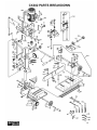
1
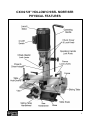
CX302 5/8” HOLLOW CHISEL MORTISER with TILTING HEAD User Manual TABLE OF CONTENTS General Safety Instructions for Machines ............................................................... 3 Specific Safety Instructions..................................................................................... 4 CX302 Features...................................................................................................... 5 Physical Features ................................................................................................... 6 Proper Grounding ................................................................................................... 7 Un-Packing ............................................................................................................. 8 Installation............................................................................................................... 8 Chisel and Bit Installation........................................................................................ 9 Basic Controls......................................................................................................... 10 Test Run ................................................................................................................. 10 ON/OFF Switch....................................................................................................... 11 Sliding Table ........................................................................................................... 11 Raising & Lowering the Head ................................................................................. 11 Depth Stop Adjustment ........................................................................................... 11 Height Stop Adjustment .......................................................................................... 12 Fence and Table Parallelism .................................................................................. 12 Squaring the Chisel with the Fence ........................................................................ 13 Tilting Head............................................................................................................. 13 0° & 30° Positive Stops Adjustment ........................................................................ 14 Swivel Head Adjustment ......................................................................................... 15 Working Height Capacity Adjustment...................................................................... 15 Quick Release Vise................................................................................................. 15 Table Hold Downs................................................................................................... 16 Column Mounted Hold Down .................................................................................. 16 Operating Tips ........................................................................................................ 17 Maintenance ........................................................................................................... 17 Cleaning.................................................................................................................. 17 Lubrication .............................................................................................................. 17 Parts Breakdown and Parts List....................................................................... 18 - 20 Warranty ................................................................................................................. 21 2 GENERAL SAFETY INSTRUCTIONS FOR MACHINES Extreme caution should be used when operating all power tools. Know your power tool, be familiar with its operation, read through the owner’s manual and practice safe usage procedures at all times. ALWAYS read and understand the user manual before operating the machine. CONNECT your machine ONLY to the matched and specific power source. ALWAYS wear safety glasses respirators, hearing protection and safety shoes, when operating your machine. NEVER leave a tool unattended while it is in operation. NEVER allow unsupervised or untrained person to operate the machine NEVER reach over the table when the tool is in operation. ALWAYS keep blades, knives and bits sharpened and properly aligned. DO NOT wears loose clothing or jewelry when operating your machine. Wear protective hair covering. ALL OPERATIONS MUST BE performed with the guards in place to ensure safety. A SAFE ENVIRONMENT is important. Keep the area free of dust, dirt and other debris in the immediate vicinity of your machine. ALWAYS use push sticks and feather boards to safely feed your work through the machine. BE ALERT! DO NOT use prescription or other drugs that may affect your ability or judgment to safely use your machine. DISCONNECT the power source when changing drill bits, hollow chisels, router bits, shaper heads, blades, knives or making other adjustments or repairs. ALWAYS make sure that any tools used for adjustments are removed before operating the machine. ALWAYS keep bystanders safely away while the machine is in operation. NEVER attempt to remove jammed cutoff pieces until the blade has come to a full stop. 3 CX302 HOLLOW CHISEL MORTISER SPECIFIC SAFETY INSTRUCTIONS ALWAYS READ and understand the user manual before operating the mortiser. MAKE CERTAIN the machine is fastened to a supporting surface to prevent it from tipping over during operation. ALWAYS KEEP hands, fingers and hair away from rotating parts. DO NOT attempt to mortise material that does not have a flat surface, unless a suitable support is used. ALWAYS position the hold downs directly over work piece to prevent work piece from lifting during operation. ALWAYS clamp the work piece securely against fence to prevent unexpected rotation while operation. BE SURE the chisel is sharp, not damaged and properly secured in the chuck before you start the machine. MAKE SURE the chuck key has been removed before starting the machine. NEVER turn the power on with the drill bit or chisel contacting the work piece. ADJUST the depth stop to avoid drilling into the table. ALWAYS turn off the power before removing scrap pieces from the table. SHOULD ANY PART of your tool be missing, damaged or fail in any way, shut off the machine immediately and remove the plug from power source. Replace any damaged or missing parts before resuming operation. MAKE SURE the switch is in the OFF position and the cord is unplugged from the power source. Clean the table/work area before leaving the machine. MAKE SURE before making any adjustments, the switch is in the “OFF” position and the cord is un-plugged from the power source. BEFORE OPERATING your mortiser make sure you have read and understood all the safety instructions in the manual and you are familiar with your mortiser. If you fail to do so, serious injury could occur. WARNING The safety instructions given above can not be complete because the environment in every shop is different. Always consider safety first as it applies to your individual working conditions. 4 CX302 MORTISER FEATURES MODEL CX302 – 5/8” HOLLOW CHISEL MORTISER with TILTING HEAD As part of the growing line of Craftex woodworking equipment, we are proud to offer the CX302, a 5/8” Hollow Chisel Mortiser with Tilting Head. The Craftex name guarantees Craft Excellence. By following the instructions and procedures laid out in this user manual, you will receive years of excellent service and satisfaction. The CX302 is a professional tool and like all power tools, proper care and safety procedures should be adhered to. Motor ................................... ................................ 3/4-HP, 110-Volts, Single Phase, 60-Hz Amp ..................................... .................................6 Speed .................................. ................................ 1,720 RPM Chisel Capacity.................... ................................ 1/4” – 5/8” Chuck Capacity ................... ................................ 1/2" Maximum Chisel Stroke....... ................................. 6-1/2” Maximum Distance (fence to center)...................... 3” Maximum Distance (chisel to table with head in extended position)....... 9-1/2” Under Table Hold Down Capacity........................................................... 5-3/4” Sliding Table Size................ .................................. 20” x 8-1/4” Sliding Table Travel (Right-Left) ..... ....................... 16” Fence Size........................... .................................. 20” x 3-9/16” Paint .................................... .................................. Powder Coated Paint Length/Width/Height ............ .................................. 20” x 16” x 30” Weight ................................. .................................. 136 lbs Warranty .............................. .................................. 3 Years 5 CX302 5/8” HOLLOW CHISEL MORTISER PHYSICAL FEATURES 6 PROPER GROUNDING Grounding provides a path of least resistance for electric current to reduce the risk of electric shock. To prevent electrical hazards, have a qualified electrician ensure that the line is properly wired. This appliance is for use on a circuit having a normal of 110 volts. Make sure that the appliance is connected to an outlet having the same configuration as the plug. If an adaptor plug is used, it must be attached to the metal screw of the receptacle. WARNING Improper connection of the equipmentgrounding conductor can result in a risk of electric shock. Check with a qualified electrician if you are in doubt as to whether the outlet is properly grounded. It is strongly recommended not to use extension cords with your CX302. Always try to position your machine close to the power source so that you do not need to use extension cords. If it necessary to use an extension cord, make sure the extension cord does not exceed 50-feet in length and the cord is 14gauge to prevent motor damage. Check for heat build up periodically. Your CX302 should be wired with a 3prongs plug fitting a 3 prong grounded receptacles as shown in figure-5. Do not remove the grounding prong to fit it into a 2pronged outlet. Always check with a qualified electrician if you are in doubt. Figure-1 110-Volts outlet for CX302 7 UNPACKING INSTALLATION The machine is properly packaged and shipped completely in crate for safe transportation. When unpacking, carefully inspect the crate and ensure that the machine and the parts are in good condition. Slide the sliding table hand wheel and the quick release vise hand wheel onto the shafts and secure them using screws provided. See figure-2. The unpainted surfaces of this mortiser are coated with a rust preventive waxy oil needs to be removed prior to operation. Use a solvent cleaner that will not damage painted surfaces. Attach the handles to the hand wheels as shown in figure-2 and secure them using screws provided. WARNING CX302 is a very heavy machine, do not over-exert yourself. For safe moving method use fork truck or get the help of an assistant or friend. Figure-2 Installing the hand wheels Before setting up your machine you should read and understand the instructions given in this manual. Slide the operating lever into the hub and secure it using lock knob as shown in figure-3. Figure-3 Installing the operating lever 8 CHISEL AND BIT INSTALLATION Push the chisel all the way into the head and tighten the lock lever shown in figure-5 securing the chisel in position. Make sure the switch is in the OFF position and the cord is unplugged from the power source before installing, servicing, or performing any adjustments. Loosen the two lock knobs on both sides of the head to expose the chuck. See figure-4. Figure-5 Installing the chisel into the head IMPORTANT Figure-4 Removing the chuck cover Make sure the drill bit bottoms out in the chisel before bottoming out in the chuck. Secure the chuck in place by using the chuck key provided. The CX302 comes with two different size bushings; 5/8” and 3/4". Choose the one that fits the chisel shank. Insert the bit into the chisel and then insert the chisel bushing up into the head with the opening in the chisel bushing facing the front of the machine. Adjust the bit so that it protrudes 1/16” from the chisel as shown in figure-6. For some woods it is necessary to install the bit so that it protrudes 3/16” from the chisel. Thread the lock lever into the head and do not fully tighten at this point. IMPORTANT The chips produced during operation escape from the opening in the chisel and make sure the opening in the chisel should always be to the right or the left, not to the front or rear. Figure-6 Bit coming out from the chisel 9 BASIC CONTROLS TEST RUN A. ON/OFF Switch: Turns the machine Once you have assembled and inspected the machine it is then time to do a test run and see if the machine powers up and runs properly or not. On/Off. B. Operating Lever: Brings the head and the chisel down on the work-piece. C. Chisel and Bit Lock Knob: Holds the chisel and the bit in position into the head. D. Fence Lock Handles: Locks the fence in the desired position. E. Table Hold-Downs: Use these two hold downs to secure the work-piece on the table for safe operation. F. Quick Release Vise Hand Wheel: All the tools and objects used for assembling the machine should be removed and cleared away during test run. Connect the machine to the correct power source and start the machine. During the test run if there is any unusual noise or vibration, shut off the machine immediately. Check all the parts you have assembled, once again and try to find out the problem. During the test run make sure the start/stop button and all the safety features on the grinder are working properly. Holds the work-piece against the fence. G. Sliding Table Hand Wheel: Adjusts the sliding table position. WARNING Do not make any adjustments while the machine is running. Turn the machine OFF and un-plug from the power source before making any adjustments. Failure to do so may cause serious personal injury. Figure-7 CX302 basic controls 10 ON/OFF SWITCH The ON/OFF switch is located on the motor featuring a “removable safety key” that allows the switch to be locked in the OFF position. When the switch is in the OFF position, remove the key to lock the switch in the OFF position. Insert the key back into the switch and unlock the switch. SLIDING TABLE The CX302 is equipped with a sliding table which allows performing multiple cuts in the same work-piece without unclamping and repositioning the work-piece. Figure-8 Operating lever The sliding table is moved horizontally to the right or to the left using the hand wheel. DEPTH STOP ADJUSTMENT RAISING & LOWERING THE HEAD The depth stop allows cutting to a desired depth and prevents cutting into the work table. The CX302 is provided with an operating lever to the right side of the head to raise or lower the head. The lever height can be adjusted to provide maximum leverage during operation. To adjust the depth stop: Turn the switch OFF and unplug the cord from the power source. To adjust the lever height: Make sure the chisel or the bit is installed properly in the head. Make sure the switch is in the OFF position and the cord is disconnected from the power source. Use the operating lever and lower the head until it is at the desired height above the work table. Loosen the lock knob securing the lever to the hub and slide the lever in or out to the desired height. Hold the head in that position and loosen the depth adjustment lower lock knob. Set the depth stop bushing up against the stop plate and re-tighten the lower lock knob. See figure-9. Secure the handle by retightening the knob. See figure-8. 11 FENCE AND TABLE PARALLELISM The fence can be moved forward or backward to the desired position and secured by two lock knobs. To adjust the fence: Turn the switch OFF and unplug the cord from the power source. Figure-9 Adjusting the depth stop bushing HEIGHT STOP ADJUSTMENT The height stop adjustment allows making the upward travel distance of the operating lever longer/shorter. Loosen the two lock knobs securing the fence and move the fence to the desired position. Measure the distance from the front edge of the table to the fence on both sides of the table. Adjust the fence so that “A” is equals to “B” as shown in figure-11. To adjust the height stop: Turn the switch OFF and unplug the cord from the power source. Loosen the upper lock knob shown in figure-10 and reposition the height stop bushing downwards and re-tighten the lock knob. Figure-11 Table parallelism Once the fence is parallel with the travel of the sliding table, re-tighten the lock knobs. IMPORTANT Figure-10 Adjusting the height stop bushing Make sure the switch is in the OFF position and the cord is disconnected from the power source while installing any parts, performing any adjustments, or servicing the machine. Failure to do so may cause serious personal injury. 12 SQUARING THE CHISEL WITH THE FENCE The chisel should be square to the table and to the fence. TILTING HEAD The head can be tilted 30° to the right and 30° to the left for angled mortises. To tilt the head: To square the chisel with the fence, make sure the fence is parallel with the sliding table first. See page-12 section “FENCE AND TABLE PARALLELISM” for details. Make sure the switch is in the OFF position and the cord is disconnected from the power source. Turn the switch OFF and unplug the cord from the power source. Hold the head with one hand and loosen the head fixing bolts with another hand using a wrench. See figure-13. Lower the head using the operating lever and tighten the head height stop bushing to hold the head in position. See page-12 section “HEIGHT STOP ADJUSTMENT” for details. Place a square on the table against the fence and the side of the chisel as shown in figure-12. Figure-13 Loosening head fixing bolts to tilt the head Figure-12 Squaring the chisel with the fence Remove the stop pin shown in figure-13 and tilt the head to the desired angle on the scale and re-tighten the head fixing bolts. Loosen the chisel lock lever and adjust the chisel so that it is square with the fence and re-tighten the lock lever. For quick head tilting adjustment, the CX302 is provided with one 0° and one 30° positive stop to the left and another 30° positive stop to the right. See figure-14. 13 Place a square on the sliding table against the chisel as shown in figure-15 and check if the chisel is perfectly square with the table surface. Figure-14 Positive stops Figure-15 Squaring the chisel with the table For quick 30° head tilting adjustment to the left, tilt the head to the left and slide the stop pin into the hole until the left side 30° positive stop rests on the stop pin set screw. For quick 30° head tilting adjustment to the right, tilt the head to the right until the head casting comes in contact with the right side positive stop set screw. If it is not square, loosen the head fixing bolts and adjust the head until the chisel is perfectly square with the table surface and re-tighten the head fixing hex bolts. Loosen the 0° positive stop hex nut, adjust the screw, and re-tighten the hex nut. To adjust the 30° positive stop: Tighten the head fixing hex bolts. Make sure the switch is in the OFF position and the cord is unplugged from the outlet. 0° & 30° POSITIVE STOPS ADJUSTMENT If the positive stops do not give a perfect angle they can be adjusted. To adjust the 0° positive stops: Turn the switch OFF and unplug the cord from the power source. Make sure the 0° positive stop is sitting on the stop pin as shown in figure-14 and install the chisel into the head. See page-8 “CHISEL INSTALLATION” for details. Tilt the head and make sure the 30° positive stop is sitting on the stop pin. Place a protractor on the sliding table surface and check if the chisel is at a perfect 30° angle with the table surface. Loosen the head fixing bolts and adjust the head so that the chisel is at 30° angle with the table surface and re-tighten the hex bolts. Loosen the hex nut on the positive stop, adjust the screw, and retighten the hex nut. 14 SWIVEL HEAD ADJUSTMENT WORKING HEIGHT CAPACITY ADJUSTMENT The head can be swiveled to the right or to the left up to 180°. The working height capacity can be adjusted by 3”. To increase the working height capacity: To swivel the head: Make sure the switch is the OFF position and the cord is disconnected from the power source. Uninstall the chisel if already installed. Loosen the two larger lock levers and tighten the smaller lock lever to widen the gap in the column sleeve casting. Make sure the switch is in the OFF position and the cord is disconnected from the power source. Loosen the two larger lock levers and tighten the smaller lock lever shown in figure-16 to widen the gap in the column sleeve casting. Raise the head by hand up to 3” maximum and loosen the smaller lever, and tighten the two larger levers securing the head. QUICK RELEASE VISE The quick release vise allows clamping the work-piece against the fence for safe operation. To use the quick vise: Simply place the work-piece between the clamp stop plate and the fence and rotate the hand wheel to clamp the work-piece. Figure-16 Lock levers Swivel the head to the desired angle and loosen the smaller lock lever. Re-tighten the larger lock levers and secure the head in position. Figure-17 Quick release vise 15 For some operations, you may want to remove the vise by removing the hex bolts securing the vise on the table surface first. COLUMN MOUNTED HOLD DOWN TABLE HOLD DOWNS CX302 is provided with a column mounted hold down which is mounted to the column and slides into the slots on the fence. CX302 comes with two hold downs to hold the work-piece on the table. The hold downs are mounted to the table. The table features 9 mounting holes for each hold down on both sides, to be mounted in different positions depending on the size of the work-piece. This hold down can be used when the table and the fence remains in the center position. Do not move the table when the column mounted hold down is being used. To install and use the column mounted hold down: Attach the hold down to the column so that the V-groove clamps of the hold down are in the slots on each sides of the column. See figure-19. Lower hold down on the work-piece and install the lock knob to secure it to the column. See figure-19. Figure-18 Hold down clamp To use the hold downs for securing the work-piece on the table: Place the work-piece on the table and install the hold downs into one of the mounting holes on the table which is closest to the work-piece. See figure-18. Adjust the hold down on the work-piece by pressing the spring loaded body clamp shown in figure-18. Once the hold down plate is sitting on the work-piece, lower the latch and secure the work-piece on the table. Figure-19 Column mounted hold down WARNING When using column mounted hold down, you may find it necessary to remove the quick release vise from the sliding table as it may interfere with your operation. 16 OPERATING TIPS Always use sharp chisel and bits when mortising. Make sure the work-piece is clamped securely and the hold downs are properly adjusted. The penetration rate of the chisel should be fast enough, preventing burning at the tip of the bit but not too fast to damage the motor. During the operation you may see smoke coming from the material or the bit, which is normal. The smoke is produced because of the chip friction and the resins in the stock being burned off. Place a piece of wood with 3/4" minimum thickness between the work-piece and the table when making mortises that extend through the work-piece. It prevents the table from damage. This sacrificial board should be slightly narrower than the workpiece allowing the vise to clamp on the work-piece. MAINTENANCE During the lifetime of your machine, you will need to practice some regular maintenance to keep your saw at peak operating performance. Regularly check the machine for any loose mounting bolts, damaged wire and plug, worn switch or any other unsafe condition. CLEANING Vacuum the wood chips and sawdust and then use a dry cloth to clean the remaining dust and dirt on the table surface after every use. Make sure to clean the moisture on the unpainted cast iron surfaces of the table which can produce rust. Use a rust preventive oil on the unpainted surface of the table if the table is not used for along period of time. LUBRICATION IMPORTANT Make sure the switch is in the OFF position and the cord is disconnected from the power source while installing any parts, performing any adjustments, or servicing the machine. Failure to do so may cause serious personal injury. All the bearings are sealed, permanently lubricated and do not need any lubrication. Apply a few drops of light machine oil to the columns occasionally after cleaning the saw dust and wood chips. 17 18 19 20 WARRANTY CRAFTEX 3 YEARS LIMITED WARRANTY Craftex warrants every product to be free from defects in materials and agrees to correct such defects where applicable. This warranty covers three years for parts and 90 days for labor (unless specified otherwise), to the original purchaser from the date of purchase but does not apply to malfunctions arising directly or indirectly from misuse, abuse, improper installation or assembly, negligence, accidents, repairs or alterations or lack of maintenance. Proof of purchase is necessary. All warranty claims are subject to inspection of such products or part thereof and Craftex reserves the right to inspect any returned item before a refund or replacement may be issued. This warranty shall not apply to consumable products such as blades, bits, belts, cutters, chisels, punches etceteras. Craftex shall in no event be liable for injuries, accidental or otherwise, death to persons or damage to property or for incidental contingent, special or consequential damages arising from the use of our products. RETURNS, REPAIRS AND REPLACEMENTS To return, repair, or replace a Craftex product, you must visit the appropriate Busy Bee Tools showroom or call 1800-461-BUSY. Craftex is a brand of equipment that is exclusive to Busy Bee Tools. For replacement parts directly from Busy Bee Tools, for this machine, please call 1-800-461-BUSY (2879), and have your credit card and part number handy. All returned merchandise will be subject to a minimum charge of 15% for re-stocking and handling with the following qualifications. Returns must be pre-authorized by us in writing. We do not accept collect shipments. Items returned for warranty purposes must be insured and shipped pre-paid to the nearest warehouse Returns must be accompanied with a copy of your original invoice as proof of purchase. Returns must be in an un-used condition and shipped in their original packaging a letter explaining your reason for the return. Incurred shipping and handling charges are not refundable. Busy Bee will repair or replace the item at our discretion and subject to our inspection. Repaired or replaced items will be returned to you pre-paid by our choice of carriers. Busy Bee reserves the right to refuse reimbursement or repairs or replacement if a third party without our prior authorization has carried out repairs to the item. Repairs made by Busy Bee are warranted for 30 days on parts and labour. Any unforeseen repair charges will be reported to you for acceptance prior to making the repairs. The Busy Bee Parts & Service Departments are fully equipped to do repairs on all products purchased from us with the exception of some products that require the return to their authorized repair depots. A Busy Bee representative will provide you with the necessary information to have this done. For faster service it is advisable to contact the nearest Busy Bee location for parts availability prior to bringing your product in for repairs. 21