1
SingleTact
USER MANUAL
MINIATURE FORCE SENSORS
EXPERIENCE
INCREDIBLE
PERFORMANCE
1
SingleTact
CONTENTS
MINIATURE FORCE SENSORS
1
Introduction
3
2
Interfaces
5
2.2 Analogue Interface
7
2.1 Pinout
6
2.3 PC Interface
8
2.4 I2C Interface
3
10
Source Code and Examples
11
3.2 An Arduino Example
16
3.1 Flashing an Arduino
3.3 .NET Example
3.4 Interface Board Source Code
Copyright © 2015 - www.SingleTact.com
12
20
22
2
3
SingleTact
MINIATURE FORCE SENSORS
1.INTRODUCTION
The SingleTact is a single element sensor that accurately and reliably measures force. The interface board
features a 2V analog output for easy DAQ integration and an I2C interface for embedded systems. This
document provides all the information necessary to interface with SingleTact including a sample Arduino digital
interface and a PC data acquisition app. The open-source code can be downloaded from:
https://goo.gl/zRDBsk. An overview of the Arduino based SingleTact system is shown in Figure 1. The
SingleTact can be used in a number of ways outlined in Table 1.
MCU
Sing leTact.com
SingleTact Capacitive
Force Sensor
5
6
7
8
4
3
2
1
Capacitive Measurement
Electronics (SingleTact Interface
Board)
Figure 1: Arduino based SingleTact System Overview
1
2
3
4
Use Case
Force
Measurement
USB to PC
UNO
USB Interface
(Arduino Uno)
System Overview
Evaluation/
Force
Measurement*1
Customer
Integration*2
Customer
Integration*3
Sin g leTact.com
Sin gle Tact.com
Sin gle Tact.com
Sin g leTact.com
MCU
MCU
MCU
Analog output. Connect to multimeter,
oscilloscope or data acquisition card
5 4
6 3
7 2
8 1
5 4
6 3
7 2
8 1
5 4
6 3
7 2
8 1
PC acquisition software
UNO
I2C digital uutput. Interface to
customer electronics
Customer reads capacitance using
their own circuitry
Table 1: The four SingleTact use cases
*1 – In addition to the data acquisition software, a .NET library is provided for simple integration into a
customer’s own software suite.
*2 – Supports over 100 SingleTact interface boards. Customers can modify interface board firmware as
needed. Source code is provided in Section 2.4.
*3 – Customer may choose to use the Silicon Labs C8051F717 Capacitance to Digital converter that is used in
the SingleTact Interface. The source code is provided in Section 3.4.
Copyright © 2015 - www.SingleTact.com
4
5
SingleTact
MINIATURE FORCE SENSORS
2.1 Pinout
The sensor is plugged into the FFC connector on the green interface board (the sensor connector pads should
face upward). The connections are outlined in Table 2. The electrical parameters are outlined in Table 3.
MCU
Sin gleTact.com
Figure 2: SingleTact configuration
Connection
Pin Number
Programming (Clock)
3
I2C Interface (SCL)
7
2
Analog output (2V swing, 0.5 to 1.5V = full
scale range)
6
7
8
Ground
Connection
4
6
Frame Sync (Pulse for each new
measurement)
4
3
2
1
5
5
I2C Interface (SDA)
5
6
7
8
8
4
3
2
1
Programming (Data)
1
Vcc (3.7V to 12V)
Table 2: The SingleTact interface board pinout.
Parameter
Value
Supply Voltage
3.6 - 12V
I2C Clock
100kHz or 400kHz
Analog Range
0 – 2 V (FSR output from 0.5V to 1.5V)
Sensor update rate (I2C or Analog)
>140Hz (depends on C8051F717 settings)
Digital Logic
3.3V
Table 3: Electrical parameters
Copyright © 2015 - www.SingleTact.com
6
SingleTact
MINIATURE FORCE SENSORS
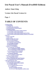
2.2 ANALOG INTERFACE
2.0V
Analog Output
As shown in Figure 3, the analog output swings from 0 to 2V,
with valid outputs ranging from 0.5V to 1.5V.
As pressure increases beyond the full scale range (FSR), the
output increases to 2V and then saturates.
An output below 0.5V may indicate negative pressures, which
occur when the sensing area is under tension. This should be
avoided since it can damage the internal structure of the
sensor. Note that if the sensor is unloaded and the output is
still under 0.5V, then a shift in the sensor’s baseline has
occurred. You can reset the baseline using the sensors digital
interface, which is specified in Section 3.
Over
pressure
1.5V
0.5V
0V
Valid
Range
Negative
pressure
0
FSR
Force or Pressure
Figure 3: SingleTact analog output
MCU
Sin gleTact.com
Figure 4: SingleTact configuration
5
6
7
8
4
3
2
1
The analog output connections are detailed here below:
Connection
No connection
No connection
No connection
Ground
Table 4: Analog connections
Pin Number
55
66
7
7
88
44
33
22
11
Connection
No connection
No connection
Analog output (2V swing, 0.5 to 1.5V = full
scale range)
Copyright © 2015 - www.SingleTact.com
Vcc (3.7V to 12V)
7
SingleTact
MINIATURE FORCE SENSORS
2.3 PC INTERFACE
An Arduino UNO board can be used to provide a USB interface to SingleTact.
Download the PC Interface from: https://goo.gl/40CqZB
The demo application is available from Github: https://goo.gl/L6kYCs
Connect the sensor to the Arduino board as follows:
MCU
Sing leTact.com
SingleTact Capacitive
Force Sensor
5
6
7
8
4
3
2
1
I2C board
Capacitive Measurement
Electronics (SingleTact Interface
Board)
USB Interface
(Arduino Uno)
Figure 5: SingleTact configuration
SingleTact Connection
No connection
Arduino UNO A4
No connection
An Arduino GND pin
USB to PC
UNO
Pin Number
55
66
77
88
44
33
22
11
SingleTact Connection
No connection
Arduino UNO A5
No connection
An Arduino 5V pin
Table 5: Shows connections between SingleTact and Arduino UNO. The SingleTact is powered from an Arduino 5V line and is connected to the
Arduino I2C bus.
Please refer to Section 3.1 for instructions on flashing the Arduino.
Copyright © 2015 - www.SingleTact.com
8
SingleTact
MINIATURE FORCE SENSORS
Run SingleTact.exe to bring up the demonstration application:
Figure 6: Demo PC DAQ software
The demonstration application can be used to change the sensor’s I2C address and modify its capacitive sensing
settings. For more information on these settings please refer to Section 3.
Copyright © 2015 - www.SingleTact.com
9
SingleTact
MINIATURE FORCE SENSORS
2.4 I2C INTERFACE
The SingleTact I2C interface supports standard (100 kbits/s) and high speed (400 kbits/s) clock rates and a 7 bit
address width. The SCL and SDA lines should be pulled up to the bus voltage, which can be between 3V and 5V.
The SingleTact software architecture is based on a 192 byte register which is detailed in Table 6. The first 127 bytes
of memory are used to store settings in flash (and are therefore persistent after a power cycle). The sensing results
are available from byte 128. A more detailed breakdown of the register is shown in Tables 7 and 8.
The interface board will always respond to two I2C addresses: 0x04 and the address specified in flash. Since the
default flash setting is 0x04, the interface board flash address has to be changed before multiple boards can be
used on the same I2C bus.
0
127
128
191
Sensor
Setting
Saved to
flash
Output
Sensor Data
Table 6: Register layout
The capacitive sensor settings are outlined in the C8051F717 datasheet.
Internally, the C0851F717 measures capacitive to 16 bit precision. This is scaled to a 12 bit digital and 2V analog
output as per the following calculation:
Raw
255
The digital scaling value is a 2 byte number stored at register locations 10 and 11 (Table 7). For increased
precision, the digital scaling value resolution is in 0.01 increments. This means that 100 equals unity scaling. The
255 offset provides the facility for a negative swing.
The internal capacitance to digital converter (CDC) operates at 140 to 4000 Hz depending on the capacitance
sensor settings (in particular the number of accumulations). Each time the CDC completes a measurement the
output register is updated, the frame index increases by one and a pulse is produced on the frame
synchronization output pin. A timestamp is calculated on the C0851F717, but since there is no crystal oscillator
on the SingleTact interface board, this timestamp is not stable and should only be used as a course estimate.
Copyright © 2015 - www.SingleTact.com
10
SingleTact
MINIATURE FORCE SENSORS
BYTE
SETTING
0
I2C Address (4-127)
1
User configurable serial number MSB
2
User configurable serial number LSB
3
Reserved
4
Reserved
5
Capacitive Sense (Accumulator) Default 0x04 *1
6
Capacitive Sense (Reference Gain) Default 0x01 *1
7
Reserved
8
Capacitive Sense (Discharge Time) Default 0x03 *1
9
Capacitive Sense (Output Current) Default 0x00 *1
10
Output digital scaling MSB
11
Output digital scaling LSB
12
Number of elements, must be 1
13
Reserved
14
Delimiter – leave as 0xFF
15
First element to scan, set to 0
16-38
Unused for SingleTact
39
Delimiter – leave as 0xFF
40
Sensor baseline MSB
41
Sensor baseline LSB
42-90
Unused for SingleTact
91
Delimiter – leave as 0xFF
92-127
Unused
Table 7: Sensor settings layout in main register. These are stored in flash and loaded each time the
SingleTact is powered on.
*1 Please consult C8051F717 datasheet for more information
Copyright © 2015 - www.SingleTact.com
11
SingleTact
MINIATURE FORCE SENSORS
BYTE
SETTING
128
Frame index MSB (increments on each new reading)
129
Frame index LSB (increments on each new reading)
130
Sensor Timestamp MSB (0.1ms increments) *1
131
Sensor Timestamp LSB (0.1ms increments) *1
132
Sensor output MSB
133
Sensor output LSB
134 - > 191
Unused
Table 7: Sensor readings layout in main register. These are updated at >140Hz (depending on capacitance
sensor settings). The frame sync digital output pulses each time these change.
*1 This should only be used as a course estimate as it is liable to drift.
I2C transmissions are limited to 32 bytes. The packet layout is detailed below.
BYTE
To Sensor
0
Read Request (0x01) or Write (0x02)
1
Read/write location in register
2
Number or bytes to read/write
3 -> (N-1)
Data to write
0 bytes for read request
N (max 31)
Table 8: I2C Packet layout (to sensor)
0xFF – signifies end of packet.
There are only two master to slave I2C commands, “read request” and “write”, which are encoded in the first
byte of the outgoing I2C transmission. The second and third bytes represent the read location and length
respectively.
An I2C slave read transmission is typically preceded by a master to slave read request command that sets the read
location. If no such read command is issued, the read location defaults to 128 (the sensor output location).
Data can be read from anywhere in the register (addresses 0 – 191), but can only be written to the first 128
bytes. Reading or writing out of this valid range will fail.
Bytes 3 to N-1 (where N is the packet length) contain any data to be written to the main register. This command
updates the internal flash memory, so the new settings are persistent beyond a power cycle.
The final byte must be 0xFF to signify the end of the packet.
Copyright © 2015 - www.SingleTact.com
12
SingleTact
MINIATURE FORCE SENSORS
I2C slave read commands simply contain the main register data up to the number of requested bytes (32 max).
BYTE
From Sensor
0-31
Main Register Data
Table 9: I2C Packet layout (from sensor)
The frame synchronization output pin (7 – see Figure 2) goes high when a new measurement is available. This can
be used to synchronize the I2C communications channel to the capacitance sensor. Alternatively, since the frame
index increments with each new frame, the sensor can be polled as quickly as possible over I2C, throwing away
duplicate data where the frame index has not incremented.
Copyright © 2015 - www.SingleTact.com
13
14
SingleTact
MINIATURE FORCE SENSORS
3.1 FLASHING AN ARDUINO
This process outlines how to flash Arduino with SingleTact firmware.
1.
2.
3.
4.
Download and install the Arduino Software from : https://goo.gl/hhQIOK
Download the Arduino firmware from GitHub: https://goo.gl/mZ03Uu
Connect the Arduino to the PC using the supplied USB cable.
Open the Arduino IDE software:
Figure 7: Arduino integrated development environment
1.
2.
3.
Go to File->Open and open “SingleTactDemo.ino”
Go to Sketch->Include Library->Add .zip Library and select “Timer1.zip”
Go to Sketch->Verify/Compile. If you receive an error make sure the Arduino is selected under Tools->Port.
You are now ready to run the demonstration application detailed in the previous Section.
Copyright © 2015 - www.SingleTact.com
15
SingleTact
MINIATURE FORCE SENSORS
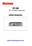
3.2 AN ARDUINO EXAMPLE
This section details the Arduino firmware required for the PC DAQ outlined in Section 2.3.
The PC to Arduino interface is setup to mirror the I2C interface, keeping the Arduino code as simple as
possible. The structure is shown in the following diagram:
PC
1 Arduino Uno
Request data (USB/UART)
N SingleTacts
Request data (I2C)
Send sensor data
Read output
buffer
Scan
sensors
Send new data to PC
Transfer to
output
buffer and
timestamp
If new data (compare itr)
- update Graph
repeats
repeats
Figure 8: Arduino example - communication architecture
Copyright © 2015 - www.SingleTact.com
repeats
Processes not
synchronised
16
SingleTact
MINIATURE FORCE SENSORS
The Arduino firmware functions as follows:
*1 Note, the Arduino contains a crystal
oscillator so it is able to produce a
more accurate timestamp than the
SingleTact interface board.
Figure 9: Arduino firmware flow diagram
The PC DAQ code functions as follows:
Figure 10: PC DAQ example code
Copyright © 2015 - www.SingleTact.com
17
SingleTact
MINIATURE FORCE SENSORS
On the PC, the Arduino appears as a virtual serial device. Data is sent to/from the Arduino using serial interface, such
as the one available in .NET.
The serial commands, which encase the raw I2C commands (shown in blue), are outlined in the following tables.
Headers and footers are added to easily deliminate serial packets. A timeout can be specified for I2C transfers. The
Arduino calculates a timestamp for each packet using the Arduino’s crystal controlled oscillator.
BYTE
From Arduino to PC
0
Header = 0xFF
1
Header = 0xFF
2
Header = 0xFF
3
Header = 0xFF
4
I2C address of sensor
5
Timeout (in 100ms increments)
6
ID (echoed in reply)
7
Read (0x01) or Write (0x02)
8
Read/ write location
9
N bytes to read/ write (max 32)
10->(10 + N-1)
Data to write
0 bytes for read request
11 + N
0xFF – signifies end of packet
12 + N
Footer = 0xFF
13 + N
Footer = 0xFF
14 + N
Footer = 0xFF
15 + N
Footer = 0xFF
Table 10: Serial packet structure (to Arduino)
Copyright © 2015 - www.SingleTact.com
18
SingleTact
MINIATURE FORCE SENSORS
BYTE
From Arduino to PC
0
Header = 0xFF
1
Header = 0xFF
2
Header = 0xFF
3
Header = 0xFF
5
1 if timeout exceeded
6
ID (echoed transmit ID)
8
Timestamp
9
Timestamp
10
Timestamp LSB
11
N I2C bytes to be sent (max 32)
12 -> 12+N
I2C data
13+N
Footer = 0xFE
14+N
Footer = 0xFE
15+N
Footer = 0xFE
16+N
Footer = 0xFE
BYTE
7
From Arduino to PC
Timestamp MSB
Table 11: Serial packet structure (from Arduino)
Copyright © 2015 - www.SingleTact.com
19
SingleTact
MINIATURE FORCE SENSORS
3.3 NET INTERFACE
This section details an example .NET DAQ App.
Download the .NET Interface and demo application from GitHub: https://goo.gl/CAZP88
For convenience the low level PC interface is encapsulated in two .NET components.
1.
2.
ArduinoSingleTactDriver – The basic Arduino interface. The user must create one of these.
SingleTact – There can be multiple SingleTacts each with their own I2C address.
Creating a SingleTact interface is as simple as:
arduinoSingleTactDriver.Initialise(COMport);
singleTact_.I2cAddressForCommunications = 0x04;
singleTact_.Initialise(arduinoSingleTactDriver);
The sensor is read using the following:
//Start sensor
//Start Arduino driver
//Set I2C address
SingleTactFrame newFrame = singleTact_.ReadSensorData(); //Get sensor data
if (null != newFrame) //If we have data
{//Process result}
Settings can be pulled from the sensor using:
singleTact_.PullSettingsFromHardware();
and sent to the sensor using:
singleTact_.PushSettingsToHardware();
The sensor settings can be modified using commands like:
singleTact_.Settings.ReferenceGain = ###;
Copyright © 2015 - www.SingleTact.com
20
SingleTact
MINIATURE FORCE SENSORS
3.4 INTERFACE BOARD SOURCE CODE
The interface board source code can be downloaded from GitHub using: https://goo.gl/Qjs62D
Programming the C8051F717 requires a 8 bit programmer, which can be purchased from Digikey (336-1182-ND).
Programming requires the Silicon Labs IDE and a free Keil compiler, which can be downloaded from:
http://goo.gl/yJLZh2
The hardware connections are as follows:
Connection
Programming (Clock) - Programmer
pin 7
None
None
Ground - Programmer pin 2 or 4 or
9
Table 12: Programming connections
Pin Number
5
66
5
7
8
8
7
4
4
3
3
2
1
1
2
Connection
Programming (Data) - Programmer
pin 4
None
None
Vcc Programmer pin 10
For convenience the Silicon Labs 8 bit programmer connector pinout is shown below. For more information
consult: http://bit.ly/1V6sCmJ
10 8
9
7
6
5
4
3
2
1
Figure 11: Silicon Labs 8 bit programmer pinout
Copyright © 2015 - www.SingleTact.com
21