1
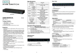
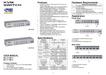
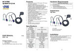
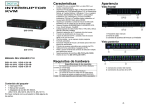
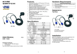
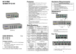
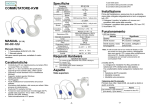
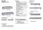
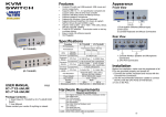
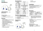
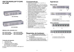
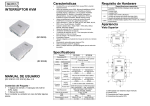
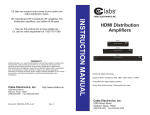
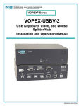
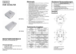
KVM SWITCH Features (IC-716-IO) Hardware Requirements Controls PCs with one PS/2 keyboard, PS/2 mouse and monitor respectively Supports the standard PS/2 mouse, Microsoft IntelliMouse (PS/2 compatible/Optical/Explorer 3.0), WheelMouse Optical, Trackball (Optical 1.0/Explorer 1.0) & Logitech TrackMan (Marble/Marble FX/ Marble+), Cordless MouseMan (Wheel/Optical), Cordless TrackMan (FX/Live) mouse, Cordless Optical TrackMan, MX300 Optical mouse Fully supports the Microsoft IntelliPoint 5.0 mouse driver & Logitech Mouse Ware driver Supports the Windows 95/98/98SE/Me/NT4.0/2000/XP, DOS, Linux, Novell Netware, FreeBSD Superior video quality - Up to 1920 x 1440, DDC, DDC2, DDC2B, DDC2AB, 200MHz Supports selecting PC by mouse clicking Real mouse identification function 4 ways PC selection - Push Button Switch or mouse clicking or Hot Key or OSD Easy to install--No software required Hot Pluggable Integral keyboard and mouse emulation for PC booting error free Auto scan function to monitor PCs Auto skips over the power-off PC Beep sound and multi selection ways on/off option for port selection 1U rack design Specifications Function IC-716-IO IC-718-IO Appearance Front View 1. Port Selection Switches (Manual type) 2. Port LEDs 3. Console Keyboard and Mouse Connector Rear View PC Connectors (IC-718-IO) USER MANUAL V1.0 IC-716-IO IC-718-IO Package Contents – 1 Smart View IC-716-IO or IC-718-IO KVM Switch 1 user manual 1 DC 9V 600mA power adapter 2 rack rails, 8 screws Any thing missed, please contact with your vendor. 6 8 Push Button Switch / Mouse Clicking Port Selection / Hot Key / OSD On Line 6 8 LEDs Selected 6 8 Keyboard PS/2 Emulation Mouse PS/2 Console Port 1x6 pin mini-DIN Female (PS/2) Connector 6x6 pin mini-DIN 8x6 pin mini-DIN -Keyboard CPU Port Female (PS/2) Female (PS/2) Console Port 1x6 pin mini-DIN Female (PS/2) Connector 6x6 pin mini-DIN 8x6 pin mini-DIN -Mouse CPU Port Female (PS/2) Female (PS/2) Console Port 1x HD-15 Female (Std. VGA/SVGA) Connector 6x HD-15 Male 8x HD-15 Male -Monitor CPU Port (Std. VGA/SVGA) (Std. VGA/SVGA) 1920x1440 (Max.), DDC, DDC2, VGA Resolution DDC2B, DDC2AB, 200MHz Power Adapter DC 9V 600mA (Min.) Scan Interval 5 sec ~ 30 sec Housing Metal Weight 1190 g 1460 g Dimensions (LxWxH) 269x104x45 mm 342x104x45 mm Cable Requirement 3L-1618C (1.8m) / 3L-1630C (3m) Rack Mount Panel 2 pcs attached 2 pcs attached Requirement specifications One highest resolution VGA, SVGA or Multisync monitor. Console One PS/2 mouse. One PS/2 keyboard. One VGA, SVGA or Multisync card. PC One 6-pin mini-DIN (PS/2) mouse port. One 6-pin mini-DIN (PS/2) keyboard port. Smart View custom cables (part # 3L-1618C or 3L-1630C) Cable or equivalent. -1- 1. Console Monitor Connector 2. CPU Port Connectors Installation Before the installation, make sure the peripherals of all PCs are grounded properly and turned off. 1. Connect the monitor, keyboard and mouse with the Console Port Connectors. 2. Use the recommended extension cables to connect the PCs with the CPU Ports of KVM Switch. 3. Turn on the PCs. -2- Operation 1. The function of LED display LED DISPLAY Light off Green light on Green light on & Red light flashing DESCRIPTION PC power off PC power on and connected PC power on, connected and selected Note: It occurs occasionally that the green light of LED display is on and the red light of LED display keeps flashing after shutting down the PC because of the PC default. The condition will not affect the regular operation of KVM switch. 2. 4 ways for PC selection – Push-button switch or hot key or OSD or mouse clicking 2-1 Push-button switch (Manual Type) Press the button on front panel to switch the CPU ports. The red light of LED indicates which PC is selected. 2-2 Mouse clicking Operation [Middle button] + [Left Button] [Middle button] + [Right Button] Function Switch to the previous PC. Switch to the next PC. Note: 2-Key Mouse is NOT applicable. PWR: It shows the status of power supply and indicates a normal power supply for the PC connected to the CPU port. CH: It shows the channel number; the IC-716-IO will display 01~06; the IC-718-IO will display 01~08. NAME: It shows the name of the equipment, and users can name the PC on their own. There are a total of 12 characters selected from the group of “A~Z”, “0~9”, “-”, “+”, “,”, “‧”, “:”. Selection BAR: It shows the selection bar (Green); you can use the ↑↓ keys on the board to move the selection bar, and the situated position indicates the selected target for giving instructions. For example, if the selection bar points at CH05 and you press Enter, then the system will switch to that particular PC or press the “Space BAR” to start editing the name. 4. Instruction Hint Field: ↑↓: Use the↑↓ keys to move the selection bar. SPACE: The “Space BAR” is used to start editing the name of the PC. ESC: Use the “Esc” key to exit the current option or exit OSD. F4: Use the F4 key to run Auto Scan, and you can set the residing time, channel display time and mode of the Auto Scan from System Setting. F9: Use the F9 key to enter into the System Setting Menu. F5: Use the F5 key to clear the values of all Name fields. -3- Making sure the cables are qualified and positioned. Q1 : A1a: Q2 : A2a: A2b: Function Switch to the previous PC. Switch to the next PC. 1. This field provides the information of the currently connected PC. 2. This field shows the list of the KVM 6 PORT or KVM 8 PORT. 3. This field shows the list of connections to the PC, and the fields are described below: Troubleshooting A1c: A1d: Select PC by Hot Key: Press either left or right [Ctrl] key twice. OSD Mode: Press the [Num Lock] key twice to access the OSD mode. Switch Menu: F4: You can use the Up, Down, Left or Right keys to move the OSD position. F8: Restore the factory default settings. Please note that all name lists will be cleared and the system settings are set to the default settings as shown in the table above. Esc: Exit the system setting and close the OSD. If you have made changes in this option, the system will ask whether or not you want to save the setting before the selected option is effective. Auto Scan Mode: You can start the OSD first and press “F4” to enter the Auto Scan Mode. If you want to scan the PC, you can select the Auto Scan Time in the System Setting for the residing time. You can adjust the Channel Display Mode and Channel Display Time from the Channel Display mode. By then, all keys on the panel, keyboard and mouse are not operable. You can only use the ESC key to exit the Auto Scan Mode. A1b: System Setting Menu: 2-3 Hot Key option Hot Key Navigation allows you to select PC from the keyboard directly. Options for Hot Key Navigation: Select PC by Hot Key OSD mode Hot Key Operation [L Ctrl] + [L Ctrl] [R Ctrl] + [R Ctrl] -4- A2c: A2d: Note: Item Description For Port Switching, Auto Scan and OSD Close, Channel the Monitor will show the Display Mode Channel information and mode selection. It shows the time for Channel displaying channel Display Time information. For Auto Scan, it shows Auto Scan the residing time for each Time port. Turn on/off the “Ctrl” hot Hot Key keys on the keyboard for Switching switching computer functions. Turn on/off the keys of Mouse Clicking the mouse for switching computer functions. Turn on/off the beeper Beeper Sound sound function. Set the auto skip function Auto Skip to on or off. The keyboard does not respond accurately. Re-install the keyboard. Unplug the keyboard from the Console Port and plug it back again. Re-install the Smart View KVM Switch. Shut down the PCs, unplug the cables from the Smart View KVM Switch and wait for five seconds. Then plug the cables back and activate the PCs. When under Auto Scan Mode, please press [Esc] key to escape. Try another keyboard. The mouse does not respond accurately. Re-install the mouse. Unplug the mouse from the Console Port and plug it back again. Re-install the Smart View KVM Switch. Shut down the PCs, unplug the cables from the Smart View KVM Switch, and wait for five seconds. Then plug the cables back and activate the PCs. Make sure the mouse is set on PS/2 mode. Try another mouse. If you are using a particular mouse, we suggest installing the mouse driver from original manufacturer to reveal the functionality of Smart View KVM Switch. Default Other Selection Full Number, Name Q3 : A3 : The mouse is out of control. The characteristic of the mouse is inefficient. Try another superior mouse and plug it back again. Start the operation after hearing the beep sound. 5 Sec 10Sec,Always, None Q4 : A4a: 5 Sec 10Sec, 20Sec, 30Sec, 60Sec There is the video problem. The setting of resolution or bandwidth is over high. Smart View KVM Switch supports the VGA, SVGA, Multisync and XGA (interlaced) with the resolution up to 1920 x 1440 Hz. The maximum bandwidth is 200 MHz. The cable is unqualified. Please use the superior cables of Smart View cables series. A4b: ON OFF ON OFF ON OFF ON OFF Q5 : A5 : F1: It provides the model name and F/W version information. Why the green light of LED display is on and red light keeps flashing after shutting down the PC? The condition is normal and caused from the PC default. The condition will not affect the regular operation of Smart View KVM switch. © C&C TECHNIC TAIWAN CO., LTD. All rights reserved. Trademarks: All the companies, brand names, product names are referred to this manual, are the trademarks or registered trademarks belonging to their respective companies. -5-