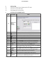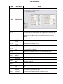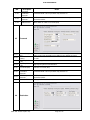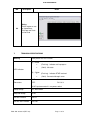
1
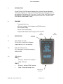
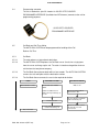
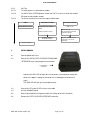
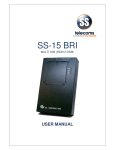
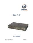
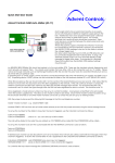
SS-06
AUTO DIAL SYSTEM
USER MANUAL
SS-06 USER MANUAL
Revision History
Revision 01
Revision 02
Revision 03
Original document
Cosmetic changes
Update GUI
2004
2007-12-06
2009-06-29
CONTENTS
1.
INTRODUCTION ......................................................................................................................... 3
2.
FEATURES .................................................................................................................................. 3
3.
DESCRIPTION ............................................................................................................................ 3
3.1
Power Supply connector ............................................................................................................ 3
3.2
CPE and LINE connectors......................................................................................................... 3
3.3
LED indicators ............................................................................................................................. 3
3.4
Programming connector............................................................................................................. 4
3.5
Call Back and Call Thru dialling ................................................................................................ 4
4
PROGRAMMING ........................................................................................................................ 5
5
INSTALLATION ........................................................................................................................... 6
6
AUTODIALLER PROGRAMMER NOTES .............................................................................. 6
7.
TECHNICAL SPECIFICATIONS ............................................................................................ 11
8.
CONTACT DETAILS ................................................................................................................ 12
DOC. NO: SS-06-14 (REV. 03)
Page 2 of 12
SS-06 USER MANUAL
1.
INTRODUCTION
The AUTO DIAL SYSTEM connects between the Customer Premises Equipment
(CPE) and a telephone line. All pre-selected destination calls made by the user will
be rerouted to a Call Back or Call Thru server. The AUTO DIAL SYSTEM will control
the call process and this process will be transparent to the caller. The AUTO DIAL
SYSTEM can accommodate 15 digits.
2.
FEATURES
-
Transparent to the user
-
LED status indicators. Call in progress and DTMF received
-
External power supply
-
Easy to install (Plug and play)
-
Programmable without disconnecting unit from the LINE
CPE
connector
3.
DESCRIPTION
3.1
Power Supply connector
9V AC input
connector
The unit uses an external 9V AC power
supply fitted with a 2.1 mm connector.
3.2
CPE and LINE connectors
RJ-11 connectors are used for connecting
LINE and CPE.
3.3
LED indicators
LED [1]
(Flashing) - Indicates call in progress.
(Solid) - Idle state.
LED [2]
(Flashing) - Indicates DTMF received.
(Solid) - Connected through server
Programming
connector
DOC. NO: SS-06-14 (REV. 03)
Page 3 of 12
LINE
connector
SS-06 USER MANUAL
3.4
Programming connector
The unit is fitted with a 4 pin SIL header. An SS-OPI OPTO-COUPLED
PROGRAMMER INTERFACE (Available from SSTelecoms) connects to the unit for
programming purposes.
SS-OPI OPTO-COUPLED
PROGRAMMER INTERFACE
3.5
Call Back and Call Thru dialling
The AUTO DIAL SYSTEM can be programmed for handling either Call
Back or Call Thru.
3.5.1
Call Back
3.5.1.1
The caller phones an international destination.
3.5.1.2
The AUTO DIAL SYSTEM phones the Call Back server. It waits for a ringing tone
from the server and hangs up the call. The caller is therefore charged the minimum
call fee from the local phone company.
3.5.1.3
The Call Back Server phones back within a few seconds. The AUTO DIAL SYSTEM
answers the call and replies with the destination number.
3.5.1.4
The Call Back Server connects the user to the required destination.
USER
Dial destination number
The user will hear
dial tone
AUTO DIAL SYSTEM
Calls the Call Back Server
Wait for X1 ring and hangs up
the call
Replies with the destination
number followed by a #
DOC. NO: SS-06-14 (REV. 03)
Wait for call
Checks and stores number
dialled
Answers the call
Gets connected
CALL BACK SERVER
Checks the number dialled
Calls back the caller
Asks the caller the destination
number followed by a #
Calls the destination number,
calls back the user and
connects both
Page 4 of 12
SS-06 USER MANUAL
3.5.2
Call Thru
3.5.2.1
The caller phones an international number.
3.5.2.2
The AUTO DIAL SYSTEM phones the toll free Call Thru server. It sends the needed
PIN code and destination number
3.5.2.3
The Server connects the user to the required destination.
USER
Dial destination number
AUTO DIAL SYSTEM
CALL BACK SERVER
Wait for call
Checks and stores number
dialled
Answers the call.
Asks and waits for PIN and
destination number
Calls the Call Thru Server
The user will hear
dial tone
Sends the PIN and
destination number
Calls the number received,
connects the user to the
destination
Gets connected
4
PROGRAMMING
4.1
Connect power to the unit.
4.2
Connect the SS-OPI OPTO-COUPLED PROGRAMMER
INTERFACE to the 4 pin programming connector.
Programming
connector
Note that the REV LED will light up if the connector is connected the wrong way.
When this happens, unplug the connector turn it 180 degrees and connect it
again.
The PWR LED will light up if connected correctly
4.3
Connect the PC to the SS-OPI using a serial cable.
4.4
Run the AutoDialProg file
4.5
Refer to the AutoDialler Programmer notes for setting up the unit. (Section 5)
4.6
Remove the OPTO-COUPLER INTERFACE connector.
DOC. NO: SS-06-14 (REV. 03)
Page 5 of 12
SS-06 USER MANUAL
5
INSTALLATION
5.1
Connect the Customer Premises Equipment to the CPE socket.
5.2
Connect the Line to the LINE socket.
5.3
Connect power to the unit at the 9V AC.
6
AUTODIALLER PROGRAMMER NOTES
NO.
Description
6.1
Numbers and
General
Functions
Detail
6.1.1
COM
Changes the COM port used for the OPTO INTERFACE
6.1.2
Diag
Selects if the data received needs to be displayed or not
6.1.3
Mode = RS232
Use Mode=RS232 for programming the AUTO DIALLER
6.1.4
Load
Loads an initialization file from the PC
6.1.5
Save
Saves the setup initialization data to the PC
6.1.6
Update
Updates the AUTO DIALER with the setup data
6.1.7
Get
Click on Get Settings to retrieve setup data from the AUTO DIALLER
6.1.8
Server number
Enter the number for the Call Thru / Call Back server in this text box
6.1.9
Number
Enter the pre-selected country code in the Number text box
6.1.10
Type
Choose a type for the pre-selected country code number or select BARRED
for barring the pre-selected country code number
6.1.11
Add/Delete
Click on Add to add the number to the list or Delete to delete it from the list.
Note: Right click on the pre-selected country code number to delete.
6.1.12
Optimise
Deletes all the duplicate number ranges in the number list
6.1.13
Undo
All the number that were deleted by optimise and be retrieved
6.1.14
Import Data
The number list can be imported via n text file. The format for the file must
be number, type. E.g. 00FFFFFFFFFFFFF,TYPE 01
DOC. NO: SS-06-14 (REV. 03)
Page 6 of 12
SS-06 USER MANUAL
NO.
Description
6.2
Global Detail
Detail
6.2.1
Initial Timeout
The time that the auto dialler waits for the 1st digit before releasing the line
6.2.2
Dial Timeout
The timeout after dialling has commenced. This timer is reset with each digit
6.2.3
Redial Break
Duration of the Line Break used to restart dialling if a number has to be
redialled
6.2.4
Predial Pause
Time after looping line before dialling
6.2.5
6.2.6
6.2.7
6.2.8
6.2.9
6.2.10
6.2.11
6.2.12
6.2.13
6.2.14
6.2.15
6.2.16
6.2.17
DTMF Tone
Period
DTMF Silence
Period
DTMF tone period, normally 0.1 second
InterDigitPeriod normally 0.1 second
Bypass Code
2 digit prefix that the user may dial to bypass the auto dialler function
PABX Access
Code
Digit Count to
Delete
Ring Count
Pulse Mode
Dialling
Enable Call
Back Mode
Call Termination
Digits
Tone Detect
Level
Direct Route on
Fail
Manual Dial
Timeout
“Inhibit after
Fail” Time
PSTN access digits if behind a PABX, up to 2 allowed recognizes ’0-9’ and
’#’. Leave blank for a direct line
DOC. NO: SS-06-14 (REV. 03)
Number of access digits to delete. Use this when behind a PABX
Number of ½ cycles of ring needed to recognize an incoming call
Set the unit to dial out in pulse mode
Enables call back operation
One or two DTMF digits that indicate to the server that the call has been
terminated – Optional
An audio threshold level for tone detection. Use 4 normally and higher
number if false tone detection occurs
Allows direct call if the server does not answer within the ‘Server Timeout’
time
Delay after dialling a NON routing number before the dialler releases the
line. This timer is reset with each digit
The dialler will be inhibited for the set number of minutes
Page 7 of 12
SS-06 USER MANUAL
NO.
6.3
6.3.1
6.3.2
6.3.3
6.3.4
6.3.5
6.4
Detail
Description
Server
Response
Server
Response Time
Auto dialler server response time. Time allowed for the server to
respond before possible direct redial
Tone Period
(*50ms)
Low Freq Limit
(*10)
High Freq Limit
(*10)
DTMF
Response
Character
Number of consecutive counts of 50 milliseconds for which the
tone must be valid
Low frequency limit for tone detection
High frequency limit for tone detection
DTMF tones can used to validate that the server has answered
Call Back
6.4.1
Call back
Response Time
Time that the dialler will wait for the server to Call Back
6.4.2
Tone Period
(*50ms)
Number of consecutive counts of 50 milliseconds for which the tone must be
valid
6.4.3
6.4.4
6.4.5
Low Freq Limit
(*10)
High Freq Limit
(*10)
User Code (PIN)
DOC. NO: SS-06-14 (REV. 03)
Low frequency limit for tone detection
High frequency limit for tone detection
Enter the User Code (PIN)
Page 8 of 12
SS-06 USER MANUAL
NO.
Detail
Description
6.4.6
Password
termination
character
Terminator DTMF code for password entry. Default = ‘#’
6.4.7
DTMF response
character
DTMF codes can be used to validate that the server is ready for the
destination number
6.4.8
Call back PIN
Allows dialler to submit a user Code (PIN)
6.5
6.5.1
6.5.2
6.5.3
6.5.4
6.5.5
6.5.6
6.5.7
Password
Password response
time
Tone Period
(*50ms)
Low Freq Limit
(*10)
High Freq Limit
(*10)
Time that the dialler will wait for the server to acknowledge the user code
(PIN). Set to 0 if the destination to be dialled is to be without any pause
Number of consecutive counts of 50 milliseconds for which the tone must
be valid
User Code (PIN)
Enter the User Code (PIN)
Password
termination
character
DTMF response
character
6.5.8
Call back PIN
6.6
Destination
DOC. NO: SS-06-14 (REV. 03)
Low frequency limit for tone detection
High frequency limit for tone detection
Terminator DTMF code for password entry. Default = ‘#’
DTMF codes can be used to validate that the server is ready for the
destination number
Only applicable in call back mode
Page 9 of 12
SS-06 USER MANUAL
NO.
Detail
Description
6.6.1
Predial Pause
Delay after PIN code acknowledged before sending the
destination number
6.6.2
Termination Digit
Terminator DTMF code for destination number, default =’#’
6.6.3
Digit Count Delete
Digits to delete from Type 1 or Type 2 numbers
6.6.4
Digits to Insert
Digits to insert in front of Type 1 or Type 2 numbers
6.7
Confirmation
6.7.1
Confirmation response
time
Time that the dialler waits to validate the call or release the line
6.7.2
Tone Period (*50ms)
Number of consecutive counts of 50 milliseconds for which the tone
must be valid
6.7.3
Low Freq Limit (*10)
Low frequency limit for tone detection
6.7.4
High Freq Limit (*10)
High frequency limit for tone detection
6.7.5
Tone Response
indicates failure
A tone response will pass or save a call depending on this
setting
No Confirmation
needed
DTMF response
character
If ticked the dialler will ignore timeouts or tones – The DTMF will
always be functional
Call Fail Code
Failure code from the server - it is always active when set.
6.7.6
6.7.7
6.7.8
DOC. NO: SS-06-14 (REV. 03)
Success code from the server - it is always active when set.
Page 10 of 12
SS-06 USER MANUAL
NO.
Dialog
Dialler responses can
be viewed here.
Cut/Copy and Paste
can be used
6.8
7.
Detail
Description
TECHNICAL SPECIFICATIONS
Housing
Black plastic 125 x 68 x 29 mm
[1] - Yellow
(Flashing) - Indicates call in progress.
(Solid) - Idle state.
LED indicators
[2] – Yellow
Connectors
(Flashing) - Indicates DTMF received.
(Solid) - Connected through server
LINE:
RJ11 6*4
CPE:
RJ11 6*4
9V AC input connector 2.1 mm power socket
Setup storage
Yes, Non-volatile
Required voltage
9V AC
Current Firmware
Rev;3.1
Current Tool Firmware
Rev:2.01
DOC. NO: SS-06-14 (REV. 03)
Page 11 of 12
SS-06 USER MANUAL
8.
CONTACT DETAILS
Office:
23 Botha Avenue
Lyttelton Manor
Pretoria, Gauteng
South Africa
Tel:
Fax:
+27 12 664 4644
+27 86 614 5625
E-mail: [email protected]
Postal address:
Postnet Suite 48
Private Bag x 1015
Lyttelton, 0140
Pretoria, Gauteng
South Africa
Sales Support:
E-mail: [email protected]
United Kingdom
E-mail: [email protected]
Technical Support:
E-mail: [email protected]
DOC. NO: SS-06-14 (REV. 03)
Page 12 of 12