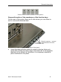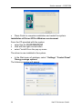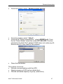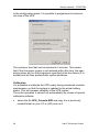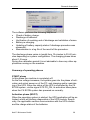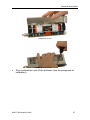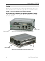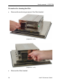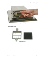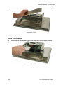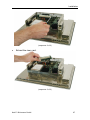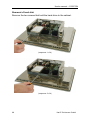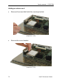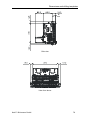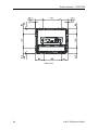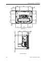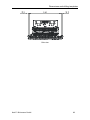
1
COMBICONTROL
C6
GB Instruction Manual
ECON IPC‘s
8.4“…17“
Mat.No.
00C6NEB-AA00
Rev.
1B
The information in this manual is subject to change and is in no way binding upon KEB (Karl E. Brinkmann GmbH).
KEB is not responsible for technical errors or other omissions in the manual, and shall not accept any
responsibility deriving from its use.
All brands and product names mentioned in this manual are trade-marks of their respective owners.
The products of the familiy C6 ECON are compliant with European Directive 2004/108/EC concerning
electromagnetic compatibility and Directive 2006/95/EC concerning the safety of electrical products,
and subsequent variations.
Instructions on disposal
Summary
Chapter 1 Preliminary operations ......................................................5
List of material provided..................................................................6
Prior to installation...........................................................................6
Notes on the guarantee ..................................................................6
Chapter 2 General description...........................................................7
Presentation ....................................................................................8
General technical specifications .....................................................8
Composition and configuration of the systems. ............................11
C6 ECON 8.4” ...........................................................................11
C6 ECON 10.4” .........................................................................11
C6 ECON 12.1” .........................................................................11
C6 ECON 15.0” .........................................................................12
C6 ECON 17.0” .........................................................................12
C6 ECON...................................................................................12
Front panel ....................................................................................13
Customization of the function keys............................................14
Removal/insertion of the membranes of the function keys .......15
Display ..........................................................................................18
Display quality TFT-LCD ...........................................................18
8.4” display features ..................................................................19
10.4” LVDS display features......................................................20
12.1” Display features ...............................................................21
15.0”Display features ................................................................22
17.0”Display features ................................................................23
Rear panel connectors..................................................................24
Expandability configurations .........................................................25
UPS (optional)...............................................................................26
Technical data ...........................................................................28
Installation and connection of UPS module ..............................29
Software installation ..................................................................33
Driver Linx module installation...............................................33
Installation of Driver UPS in Windows environment ..............36
Calibration..............................................................................38
Summary of operating phases ..................................................39
Deactivation and removal of UPS module ................................41
Battery replacement ..................................................................43
Cooling ..........................................................................................48
Procedure for cleaning fan filter.............................................50
System grounding .........................................................................52
Power supply.................................................................................54
Mass memory unit.........................................................................55
Compact Flash ..........................................................................55
Hard disk ...................................................................................56
Touchscreen .................................................................................56
Setup of Touchscreen controller ...............................................56
Installation of software in various Windows environments........57
Installation of software in MS-DOS environment ......................57
Chapter 3 Installation.......................................................................59
How to start the system ................................................................60
Start-up......................................................................................60
Shutdown...................................................................................60
Panel assembly.............................................................................61
C6 ECON wall mounting ...............................................................62
Access to internal parts.................................................................63
Removal of the rear cover (upper part) .....................................63
Removal of the rear cover (lower part)......................................65
Riser card removal ....................................................................66
Removal of hard disk.................................................................68
Ram installation/removal ...........................................................71
Adding an add-on card ..............................................................72
Addition / replacement of Compact Flash modules...................74
Chapter 4 Dimensions and drilling templates...................................77
Dimensions of system C6 ECON 8.4” .......................................78
Dimensions of system C6 ECON 10.4“ .....................................81
Dimensions of system C6 ECON 12.1“ .....................................84
Dimensions of system C6 ECON 15.0” .....................................87
Dimensions of system C6 ECON 17.0” .....................................90
Dimensions of system C6 ECON ..............................................93
Chapter 5 Connectors pin-out ..........................................................95
Connector for keyboard/mouse PS/2............................................96
Serial interface connector DB9 RS232 .........................................96
Serial interface connector DB15 multistandard ............................97
USB connector type A...................................................................97
VGA connector..............................................................................98
RJ45 ETHERNET connector ........................................................98
Preliminary operations
Chapter 1
Preliminary operations
This chapter contains the list of material
included in the packing box.
•
•
•
Karl E. Brinkmann GmbH
List of material provided
Prior to installation
Notes on the guarantee
5
User's manual – C6 ECON
List of material provided
The following is a list of the material included in the packaging:
•
•
•
•
•
•
•
System (as ordered configuration)
Adaptor wire for keyboard / mouse (Y-shaped).
Label kit for personalization of front panel keys.
User's Guide
Support CD Rom.
Document with "Conditions of Guarantee" (keep for any future
repair work).
Hooks for panel fastening.
On request:
•
Operating system kit (pre-loaded software, license for use, manual and magnetic supports).
Prior to installation
After you have checked the contents of the package, you should
keep the packing materials as they may be needed for transporting
the system in the future.
After unpacking the system, place all of the material on a work surface and carefully follow the instructions set forth in the following
chapters.
Notes on the guarantee
The guarantee is regulated by the document "Conditions of Guarantee" which is provided with the system.
6
Karl E. Brinkmann GmbH
General description
Chapter 2
General description
This chapter describes the general features of the systems.
• Presentation
• General technical specifications
• Composition and configuration of
the systems.
• Front panel.
• Display
• Rear panel connectors
• Expandability configurations.
• Cooling.
• System earth
• Power supply.
• Mass memory unit
• Touchscreen
Karl E. Brinkmann GmbH
7
User's manual – C6 ECON
Presentation
The new C6 ECON family was designed to provide the widest possible scalability in performance and functionality. It based on the CPU
“all in one” ASEM 951 for processors of the TRANSMETA families of
processors, designed according to a modular structure that always
provides the right solution of all automation needs.
General technical specifications
Front panel specifications
Protection
IP65
Input devices
Touch Screen
4 function buttons
Display LCD 8.4”
Colore TFT VGA 8.4” 350 cd/mq tipico - 2 x CCFL
Display LCD 10.4”
Color TFT VGA 10.4" 400 cd/mq tipico - 2 x CCFL
Display LCD 12.1”
Color TFT VGA 12.1" 350 cd/mq tipico - 2 x CCFL
Display LCD 15.0”
Color TFT VGA 15.0" 450 cd/mq tipico - 4 x CCFL
Display LCD 17.0”
Color TFT VGA 17.0" 300 cd/mq tipico - 4 x CCFL
USB
1 port (2.0)
Technical specifications
8
Assembly
Panel (C6 ECON wall mounted)
Motherboard
ASEM CPU 951
Chipset
Intel 915GM Express + ICH6
Processor
Intel Celeron M ULV up to 1 GHz
RAM
(min.- max.)
256MB ÷ 1GB DDR2-533
(1 x 200 pin SODIMM socket)
Video interface
32 bit VGA/SVGA/XGA/SXGA, external connector
DB15 - graphic controller Intel GMA 900
Video RAM
64/128 MB of memory selectable from system setup
Colour resolution
C6 ECON – 8.4”
C6 ECON – 10.4”
C6 ECON – 12.4”
C6 ECON – 15.0”
C6 ECON – 17.0”
800 x 600
800 x 600
800 x 600
1024 x 768
1280 x 1024
256K
256K
16.2M
16.2M
16.2M
Karl E. Brinkmann GmbH
General description
Serial interface
1 x RS-232 (DB9)
Ethernet
2 x 10/100 Mbps (RJ45)
Keyboard/mouse interface
1 x Minidin PS/2 with uncoupler
Interface USB (2.0)
1 on front panel
1 internal available on motherboard
4 connectors located on back of machine
Expansion slots
1 internal PCI slot (optional)
1 module PC/104 Plus internal*
(see paragraph on expandability configuration in the
chapter on general description)
Mass memory interfaces
1 x SATA/150, 1 x PATA/100 (used by Compact
Flash), 1 slot Compact Flash type II with external
access
Power supply
18-36 VDC (3.00A @ 18V – 1.50A @ 36V)
at maximum load (**)
Consumption
C6 ECON
C6 ECON (Box)
Relative humidity
maximum 80% without condensation
Storage temperature
-20°C ÷ +60°C
54W
34W
Operative temperature for C6 0°C ÷ 50°C
ECON without hard disk with
LCD 8.4”, 10.4”, 12.1”, 15.0”
and C6 ECON
Operative temperature for C6 0°C ÷ 45°C
ECON without hard disk with (estimated increased power 5W)
LCD 17.0”
Operative temperature for C6 0°C ÷ 45°C
ECON with hard disk with
(estimated increased power 8W)
LCD 8.4”, 10.4”, 12.1”, 15.0”,
17.0”
(*) Use of the internal PCI slot precludes the use of add-on such as
PC/104Plus.
(**) with LCD 15.0”, without hard disk, add-on 3W.
Karl E. Brinkmann GmbH
9
User's manual – C6 ECON
Weight and dimensions (see chapter 4 on dimensions and drilling template)
C6 ECON - 8.4”
Frontal panel: 250 x 210 mm.
Weight 3.1 Kg
C6 ECON - 10.4”
Frontal panel: 300 x 245 mm.
Weight 4.0 Kg.
C6 ECON - 12.1”
Frontal panel: 335 x 270 mm.
Weight 4.6 Kg.
C6 ECON - 15.0”
Frontal panel: 390 x 315 mm.
Weight 5.3 Kg.
C6 ECON - 17.0”
Frontal panel: 455 x 355 mm.
Weight 6.7 Kg.
C6 ECON - Box
Weight 2.0 Kg.
Options
10
Display LCD 15.0” HL (High
Luminance)
Colour TFT VGA 15.0" 600 cd/m2 typical - 4 x CCFL
Expansion bus
PC/104 Plus or PCI internal (one overrides the other)
Hard Disk
1 x 2.5” SATA
Serial ports
1 x RS-232/422/485 (2^) (DB15)
1 x RS-232/422/485 (2^) (DB15), RS-422/485 optically insulated
Parallel port
1 x SPP, EPP, ECP bi-directional (DB25)
UPS
Fastened on the back of the PC cell, minimum
backup time 15 minutes
External power supplier
On DIN rail, 220V/AC Æ 24 V/DC, 60W
WLAN
Kit Wireless LAN 802.11b, complete with antenna
Karl E. Brinkmann GmbH
General description
Composition and configuration of the systems.
The C6 ECON systems can be provided with displays of: 8.4”, 10.4”,
12.1”, 15.0” e 17.0”.The C6 ECON systems do not have any display
(used in panel or on wall).
C6 ECON 8.4”
This system is composed of the base module and the display of 8.4”.
C6 ECON 8.4”
C6 ECON 10.4”
This system is composed of the base module and the display of 10.4”.
C6 ECON 10.4”
C6 ECON 12.1”
This system is composed of the base module and the display of 12.1”.
C6 ECON 12.1”
Karl E. Brinkmann GmbH
11
User's manual – C6 ECON
C6 ECON 15.0”
This system is composed of the base module and the display of 15.0”.
C6 ECON 15.0”
C6 ECON 17.0”
This system is composed of the base module and the display of 17.0”.
C6 ECON 17.0”
C6 ECON
System composed of base module with flange for installation rear
panel installation.
C6 ECON
12
Karl E. Brinkmann GmbH
General description
Front panel
The front is made of a support anodized aluminium with a polyester
film that is resistant to impact and chemicals. The rear body is made
of nickel plated steel sheet metal to ensure electromagnetic shielding
in order to resolve issues of EMI and RFI.
Front panel in
aluminium with
protection IP65
Touchscreen with
5 wires
LCD display
LED power on
Front USB
port
protected
Detail of front panel
USB front port
protection plug
Front USB
port
USB port detail
Karl E. Brinkmann GmbH
13
User's manual – C6 ECON
Customization of the function keys
On the front panel there are 4 function keys that the user can customize, in terms of both appearance and function. The default settings for the 4 keys are those of the keys F1, F2, F3, and F4 of a
standard keyboard.
Function keys can be customized in appearance
and function
The system is provided with a set of pre-printed labels with the standard functions of Windows and with blank labels for the user to customize.
Special function keys kit
14
Karl E. Brinkmann GmbH
General description
Detail of labels installed standard on the systems
Removal/insertion of the membranes of the function keys
On the rear of the system there are 4 slots where you can either insert or remove the desired label.
Slots for insertion / removal
of membranes of function
keys.
•
special slots on back of front panel
Insert the label with the symbol to match to the key facing outwards after folding the lower edge of the label 90° in the opposite
direction of the symbol so that when it is completely inserted in
place it adheres to the panel.
Karl E. Brinkmann GmbH
15
User's manual – C6 ECON
•
(sequence 1 of 3)
Insert the label all the way into the pocket.
(sequence 2 of 3)
16
Karl E. Brinkmann GmbH
General description
inserted labels
Detail of fully inserted key customization labels
To remove the labels
• Grasp the label with a pincer and extract it.
Detail of label extraction
Karl E. Brinkmann GmbH
17
User's manual – C6 ECON
Display
The front panel of the C6 ECON systems includes a backlit LCD
module.
The display may be:
•
•
•
•
•
8.4” TFT (2 lamps) with a resolution of 800 x 600 pixels, 262144
colours.
10.4” LVDS (2 lamps) with a resolution of 800 x 600 pixels,
262144 colours.
12.1” TFT (2 lamps) with a resolution of 800 x 600 pixels,
262144 colours.
15.0” TFT (4 lamps) with a resolution of 1024 x 768 pixels,
16194277 colours.
17.0” TFT (4 lampade ) with a resolution of 1280 x 1024 pixel,
16194277 colori.
The display unit is contained in a mechanical cartridge.
Display quality TFT-LCD
The LCDs may have defective pixels (always on or always off). The
unique manufacturing process of the LCD panels does however
keep the defect rate very low, taking into account the high number of
elements of the RGB triad on the panel. The maximum admissible
number or defects is stated by the manufacturer and is shown in the
following table.
LCD panel
8.4”
10.4”
12.1”
15.0”
17.0”
18
Maximum admissible number
of pixels on
8
8
8
6
6
Maximum admissible number
of pixels off
8
8
8
7
8
Maximum admissible
number of defective
pixels (on+off)
15
15
15
10
10
Karl E. Brinkmann GmbH
General description
8.4” display features
The LCD 8.4” module has a maximum resolution of 800x600, active
matrix backlit by two fluorescent lamps
Brightness is adjusted in the setup.
8.4” display features
Dimensions
8.4”
Technology
LCD-TFT active matrix
Visible area
170.4 (A) x 127.8 (L) mm
Resolution
800 x 600
Colours
262144
Dot Pitch
0.213 mm
Brightness
350 cd / m² typical
Horizontal visual angle
(left + right)
100° typical
Vertical visual angle
(high + low)
90° typical
Contrast value on optimal angle
250:1 typical
Response (Rise)
50 ms maximum
Response (decay)
50 ms maximum
Power supply
3.3 V
Surface finish
Anti-glare
Backlit
Two CCFL (Cold Cathode Fluorescent Lamp)
Karl E. Brinkmann GmbH
19
User's manual – C6 ECON
10.4” LVDS display features
The LCD 10.4” LVDS module has a maximum resolution of 800x600,
by two fluorescent lamps, brightness is adjusted in the setup.
10.4” display features
20
Dimensions
10.4”
Technology
LVDSx
Visible area
211.2 (A) x 158.4 (L) mm
Resolution
800 x 600
Colours
262144
Dot Pitch
0.264 mm
Brightness
400 cd / m² typical
Horizontal visual angle
(left + right)
120° typical
Vertical visual angle
(high + low)
100° typical
Contrast value on optimal angle
450:1 typical
Response (Rise)
8 ms maximum
Response (decay)
17 ms maximum
Power supply
3.3 V
Surface finish
Anti-glare
Backlit
Two CCFL (Cold Cathode Fluorescent Lamp)
Karl E. Brinkmann GmbH
General description
12.1” Display features
The LCD 12.1” module has a maximum resolution of 800x600, active
matrix backlit by two fluorescent lamps
Brightness is adjusted in the setup.
Display features 12.1”
Dimensions
12,1”
Technology
LCD-TFT active matrix
Visible area
246.0 (A) x 184.5 (L) mm
Resolution
800 x 600
Colours
16 million
Dot Pitch
0.3075 mm
Brightness
350 cd / m² typical
Horizontal visual angle
(left + right)
140° typical
Vertical visual angle
(high + low)
120° typical
Contrast value on optimal angle
500:1 typical
Response (Rise)
50 ms max
Response (decay)
50 ms max
Power supply
3.3 V
Surface finish
Anti-glare
Backlit
Two CCFL (Cold Cathode Fluorescent Lamp)
Karl E. Brinkmann GmbH
21
User's manual – C6 ECON
15.0”Display features
The LCD 15.0” module has a maximum resolution of 1024x768, active matrix backlit by four fluorescent lamps
Brightness is adjusted in the setup.
Display features 15.0”
22
Dimensions
15,0”
Technology
LCD-TFT active matrix
Visible area
304.1 (A) x 228.1 (L) mm
Resolution
1024 x 768
Colours
16M
Dot Pitch
0.297 mm
Brightness
450 cd / m² typical
Horizontal visual angle
(left + right)
170° typical
Vertical visual angle
(high + low)
170° typical
Contrast value on optimal angle
400:1 typical
Response (Rise)
25 ms maximum
Power supply
3.3 V
Surface finish
Anti-glare
Backlit
Four CCFL (Cold Cathode Fluorescent Lamp)
Life cycle of lamps
50000 hours
Karl E. Brinkmann GmbH
General description
17.0”Display features
The LCD 17.0” module has a maximum resolution of 1280x1024, active matrix backlit by four fluorescent lamps
Brightness is adjusted in the setup.
Display features 17.0”
Dimensions
17,0”
Technology
LCD-TFT active matrix
Visible area
337.92 (A) x 270.336 (L) mm
Resolution
1280 x 1024
Colours
16M
Dot Pitch
0.264 mm
Brightness
300 cd / m² typical
Horizontal visual angle
(left + right)
160° typical
Vertical visual angle
(high + low)
160° typical
Contrast value on optimal angle
1000:1 typical
Response (Rise)
3,7 ms maximum
Power supply
5V
Surface finish
Anti-glare
Backlit
4 CCFL (Cold Cathod Fluorescent Lamp)
Life cycle of lamps
50000 hours
Karl E. Brinkmann GmbH
23
User's manual – C6 ECON
Rear panel connectors
COM3
UPS connector
(optional)
Parallel
(optional)
LAN 1
LAN 2
COM1
VGA
Input 24 V DC
Keyboard
/ Mouse
Earth screw
USB ports 2.0
detail of connectors of rear panel
Reset CPU
LED FAIL
Disk activity LED
Watch-dog activity LED
LED Power/UPS
Reset Watch-DOG
detail of buttons and LED of rear panel
24
Karl E. Brinkmann GmbH
General description
Expandability configurations
The C6 ECON systems are configured in the factory with two different types of expansion:
• without internal PCI slot
detail of inside of C6 ECON without PCI slot
•
with internal PCI slot
Internal
PCI slot
detail of inside of C6 ECON with PCI slot
(the PC cell is equipped with a tachometric fan with filter)
Karl E. Brinkmann GmbH
25
User's manual – C6 ECON
When the system is configured to mount an internal PCI add-on card
the PCI connector of the standard PC/104Plus is no longer
available:
UPS (optional)
The UPS module provides power to the system for a maximum of 15
minutes* if there is no external power supply at 24VDC.
It can be placed remotely with a special extension cord up to 1 m
from the central unit and it is equipped with configurable and automatic management of the controlled shutdown operations. It can be
added in all versions of the C6 ECON systems
Detail of UPS module
*Backup time depends on machine configuration (type of display,
add-on modules, etc.) with fully charged batteries.
When there is a power outage, the UPS starts working. The two
green LED's on the front and rear panels of the system begin flashing.
26
Karl E. Brinkmann GmbH
General description
LED power on
Detail of front panel C6 ECON
LED
Power/UPS
detail of LED of rear panel
The activity of the UPS can be controlled via the module of the operating system(WindowsXP®) backup energy source -> energy savings options in the control panel. With this module, you can check
the state of battery charge, enable/disable and programme the intervention time of the UPS.
If the UPS is removed or not used for a long period of time, you will
need to charge it completely (this takes about 1.5 hours) by connecting the module to an C6 ECON operating system.
Karl E. Brinkmann GmbH
27
User's manual – C6 ECON
Technical data
Power supplies
Nominal input voltage
Input voltage range
Max. current input
Nominal output voltage
Nominal output current
Activation threshold
Protections on power supply
24V
18-36V
1.7 A
12V
2.5 A
Approximately 16V
Welded internal fuse F4 A on input
Batteries
Type
Charge
Duration at nominal charge
Duration in backup
2 cells lead Cyclon D 5 Ah
Rapid: Constant current 3 A
Backup: Constant voltage 5V
*15 min. at 25°C with fresh, charged batteries
10 years at 25°C
4 years at 35°C
1 year at 50°C
*Backup time depends on machine configuration (type of display,
add-on modules, etc.) with fully charged batteries.
Protections on batteries
Type
Welded internal fuse F15 A
Interruption of rapid charging at low (< 5 °C) and high (>65 °C) temperatures
Automatic release of batteries at end of discharge
Mechanics
Dimensions
Weight
Assembly
235 x 65 x 50 mm ( L x H x S )
1200 g. approx.
On back of machine C6 ECON or immediately nearby using the extension cord (optional) of 1 m
Connections
Connections
28
Shielded cable of approximately 20 cm with connector
DB15 on the end
Karl E. Brinkmann GmbH
General description
Ambient
Operating
temperature
Electromagnetic
compatibility
+0° ÷ +50°C
Emissions: Standard EN 55022, Class: B
Immunity: Standard EN 55082, Ambient: industrial
Pinout Connector DB15 male
Pinout Connector DB15 male
PIN
1/2/9
7 / 8 / 15
6 / 13 / 14
4
5
10
12
3
11
signal
Mains power supply - power
Ground – power
Backup power supply – power
Smbus data line - signal
Smbus clock line - signal
Smbus – signal
Smbus power supply – signal
PSON line for UPS activation - signal
N.C.
Installation and connection of UPS module
To install the UPS module, the system must be equipped with the
appropriate connector.
• Disconnect the system from the power supply (if connected).
• Remove the two screws from the lower part of the rear cover.
(sequence 1 of 7)
Karl E. Brinkmann GmbH
29
User's manual – C6 ECON
(sequence 2 of 7)
•
Position the UPS module on the back of the system as shown in
the figure and connect the cable of the UPS to connector DB15
located on the system just below the power supply connector.
•
Attach the UPS module to the system with the two screws.
30
(sequence 3 of 7)
Karl E. Brinkmann GmbH
General description
(sequence 4 of 7)
(sequence 5 of 7)
Karl E. Brinkmann GmbH
31
User's manual – C6 ECON
(sequence 6 of 7)
(sequence 7 of 7)
•
•
32
Reconnect the power supply cables to the system and provide power.
The system will now come on. After about 6 seconds the UPS
device will become operational.
Karl E. Brinkmann GmbH
General description
Software installation
Driver Linx module installation
From the CD provided with the system, select the file
setup_dlportIO.exe and run it.
The following screens will appear
•
Press Next to continue installation
•
Press Yes to continue installation
Karl E. Brinkmann GmbH
33
User's manual – C6 ECON
•
Press Next to continue installation
•
Select the folder for installation and press Next to continue.
•
Select minimal installation (compact) Press Next to continue installation
34
Karl E. Brinkmann GmbH
General description
•
Press Next to continue installation
•
Press Next to continue installation
•
Press Next to continue installation
Karl E. Brinkmann GmbH
35
User's manual – C6 ECON
• Press Finish to complete installation and restart the system.
Installation of Driver UPS in Windows environment
From the CD provided with the system:
• select the file C6 ECONUPS.INF
• click with the right mouse button
• select "install2 from the pop-up menu.
The driver is now installed in the system.
•
In the Start menu of windows, select “ Settings” “Control Panel”
“Energy savings options”
The following window will appear
36
Karl E. Brinkmann GmbH
General description
•
From the window, select “ Backup energy source”
•
•
From the window, select “ Select”.
From the list "Select manufacturer", select ASEM S.p.A.. From
the list "Select Model" select the model OT1200 UPS. The item
selected in the field “Port” (default COM1) does not make any difference since it is not used for this purpose.
•
Press the End button.
The system must now:
• Activate communications with the UPS.
• Signal presence of UPS active (details box).
• Provide estimated capacity of group. (status box)
Karl E. Brinkmann GmbH
37
User's manual – C6 ECON
In the configuration panel, it is possible to programme the intervention time of the UPS.
The minimum time that can be selected is 2 minutes. This means
that if the line power supply is not restored within this time, the operating system will run the programme specified in the box below (if inserted) and will then proceed with system shutdown.
Calibration
It is advisable to calibrate the UPS yearly during scheduled machine
maintenance, so that the system is updated to the actual battery
status. This will increase reliability of the UPS system.
The entire operation is carried out automatically by means of special
calibration software.
•
38
select the file UPS_Console.EXE and copy it in a previously
created folder on your CF or (HD) and run it
Karl E. Brinkmann GmbH
General description
The software performs the following sequence:
• Check of battery charge.
• Discharge of batteries.
• Verification of reaching end of discharge and validation of same.
• Battery re-charging
• Updating of battery capacity status if discharge procedure was
successful.
• Memorization in a log file of the result of the procedure.
The discharge phase varies in length from 15 minutes to 30-40 minutes depending on system configuration. The charging phase takes
about 1.5 hours.
During the calibration period it is not advisable to have any other applications running on the machine.
Summary of operating phases
START phase
In this phase the machine is completely off.
As the line voltage increases, the system goes into the phase of activation and actual power on of the PC, and charging and/or maintaining of the UPS. Since the status of the UPS is controlled by the C6
ECON system, via the signal ATX PS_ON, its activation takes place
when the C6 ECON system has powered on normally.
Activation phase (BOOT)
When the operating system is started, the UPS application will be activated, which will perform diagnostics of the UPS module. Specifically, the application verifies communication with the UPS module
and the charge status of the batteries.
Karl E. Brinkmann GmbH
39
User's manual – C6 ECON
Monitoring phase of the status of the power line by the application dedicated to the UPS function.
The application accesses the information on the UPS unit via the
Smbus system bus. Any power outage during this phase will cause
the start of a countdown. If the countdown exceeds 2 minutes, the
shutdown procedure is irreversibly started. Brief power outages will
instead have no effect on continued PC operation.
Shutdown phase
This phase lasts a varying amount of time, not known in advance,
which is contingent upon the number and type of active applications.
When the line power supply comes back on during this phase, it
does not in any way affect the correct execution of the shutdown
procedure, which must in any case be completed. Upon completion
of this phase, if the line power has not come back on, the system will
shut off the power suppliers of the C6 ECON system, of the UPS
module via the Mpson signal, and it will place the machine in standby
status (return of line voltage)
The return of line voltage places the system back in START status.
Standby phase
Constant monitoring of the line voltage in which its return causes the
machine to restart. There are two specific cases:
• Shutdown desired by the user, in which the machine must shut
down even if there is mains power supply. In this case the machine can be turned back on by turning the line voltage off and
then back on.
• Shutdown caused by line voltage failure in which the UPS powers the machine until the shutdown sequence is complete. At this
point, both (C6 ECON and UPS) are de-activated. The machine
restarts as soon as the line voltage is restored (START phase). If
the line voltage is restored during the shutdown phase, the system will start the machine again upon conclusion of this phase.
40
Karl E. Brinkmann GmbH
General description
Deactivation and removal of UPS module
If the machine undergoes normal shutdown via the operating system,
there are no special procedures for the de-activation of the UPS
since it is shut off by the machine to which it is connected. If you
want to shut down the machine by means of its power supply, once
the UPS has intervened, you will need to deactivate it manually by
pressing the button on its side
UPS deactivation
button
Detail of UPS deactivation button
(sequence 1 of 4)
Karl E. Brinkmann GmbH
41
User's manual – C6 ECON
•
Remove the two screws of the UPS.
(sequence 3 of 4)
(sequence 4 of 4)
42
Karl E. Brinkmann GmbH
General description
Battery replacement
How long the batteries last depends on a number of factor, but it is
mostly due to high temperatures that their life cycles are reduced.
During the life cycle of the machine, even if they are quite resistant,
they may need to be replaced.
To replace the batteries:
•
Remove the two screws of the UPS cover.
(sequence 1 of 3)
•
Lift and remove the cover.
(sequence 2 of 3)
•
Cut the nylon clamps that hold the batteries in place.
Karl E. Brinkmann GmbH
43
User's manual – C6 ECON
(sequence 2 of 3)
Detail of removed clamps
•
Disconnect the terminal wires. Be very careful not to cause short
circuits, which might damage the unit.
(sequence 2 of 3)
44
Karl E. Brinkmann GmbH
General description
Detail of removed batteries
•
Place a new set of clamps in the slots of the UPS to hold the
new batteries.
(sequence 2 of 3)
•
Reconnect the batteries to the terminal wires. Carefully note the
polarity. Inverted polarity may damage the unit.
(sequence 2 of 3)
NB: Replace the batteries with the same cells (Cyclon type D 5Ah)
Karl E. Brinkmann GmbH
45
User's manual – C6 ECON
(sequence 2 of 3)
•
Tighten the clamps and lock the batteries in their seat.
(sequence 2 of 3)
•
Tighten the clamps and lock the batteries in their seat.
(sequence 2 of 3)
•
46
Put the cover back on and screw it down.
Karl E. Brinkmann GmbH
General description
(sequence 2 of 3)
•
(sequence 2 of 3)
Run a calibration cycle of the batteries (see the paragraph on
calibration).
Karl E. Brinkmann GmbH
47
User's manual – C6 ECON
Cooling
On the rear compartment and on the body of the display, there are
holes that allow air circulation through natural convection inside the
system. The unit is designed to be installed vertically.
NB: Be sure not to obstruct the ventilation openings. Periodically clean the filters as explained below for the version with
forced ventilation.
Cool air intake
Cool air intake
Cool air intake
detail of C6 ECON ventilation holes with internal PCI slot
Cool air intake
detail of C6 ECON ventilation holes with internal PCI slot
48
Karl E. Brinkmann GmbH
General description
Cool air intake
Cool air intake
detail of C6 ECON ventilation holes without internal PCI slot
Karl E. Brinkmann GmbH
49
User's manual – C6 ECON
Procedure for cleaning fan filter
•
Remove the anchoring screws of the filter bracket.
(sequence 1 of 3)
(sequence 1 of 3)
•
50
Remove the filter bracket.
Karl E. Brinkmann GmbH
General description
(sequence 2 of 6)
•
Remove the filter.
(sequence 3 of 3)
Karl E. Brinkmann GmbH
51
User's manual – C6 ECON
System grounding
It is absolutely necessary to connect the machine to the ground wire
by means of suitable wiring connected to the ground screw.
• Remove the ground screw
Earth screw
(sequence 1 of 2)
•
Insert the wire end eyelet between the rosettes in the following
sequence:
1. Screw (M5x12)
2. Grover rosette
3. Flat rosette
4. Eyelet faston
5. Toothed rosette
Screw (M5x12)
Wire end eyelet
Flat rosette
Toothed rosette
Grover rosette
52
Karl E. Brinkmann GmbH
General description
(sequence 2 of 6)
•
Re-tighten the system ground screw.
(sequence 2 of 2)
Karl E. Brinkmann GmbH
53
User's manual – C6 ECON
Power supply
The system must be powered with at 24VDC nominal (+18V÷36V),
with external cut-off (there is no main switch for the system).
•
Remove the two-pole connector from the system
(sequence 1 of 3)
•
Connect the positive pole and the negative one for power supply
(also see the label on the back of the machine) to the respective
terminals of the two pole connector with wires with a suitable
cross section.
(sequence 2 of 3)
54
Karl E. Brinkmann GmbH
General description
(sequence 3 of 3)
Mass memory unit
In its various versions, the system can optionally be equipped with
the following mass memory units:
Compact Flash
The system can house an externally accessible Compact Flash
module.
Detail of Compact Flash module
Extractable
Compact Flash
Detail of positioning of Compact Flash
Karl E. Brinkmann GmbH
55
User's manual – C6 ECON
Hard disk
The system may optionally house an internal 2.5" hard disk.
Detail of positioning of hard disk
The hard disk is to be connected by a 44-pole flat cable, which must
be inserted in the J8 connector of the CPU 951, which can be accessed by removing the rear cover.
Touchscreen
Setup of Touchscreen controller
The 5-wire resistive touchscreen is managed by a dedicated controller that the system sees as a fourth serial port.
The enabling/disabling of the port, the I/O address and its IRQ must
be selected in the screen Special OEM Features of the Setup.
These parameters are read automatically by the Plug & Play operating systems (Windows 95, 98, Mw, 2000, XP) which will create a
COM port associated with the device.
It is advisable to set the touchscreen to the address I/O 2E8h, with
IRQ 5. You will obtain a port with the address of the COM 4 standard
and a non-shared interrupt with other standard serial ports.
Using Windows NT4.0 (which is not a Plug & Play operating system),
the COM port must be created manually. From the control panel, add
a new port, assigning the I/O addresses and the IRQ previously established in the Setup.
56
Karl E. Brinkmann GmbH
General description
Installation of software in various Windows environments
•
•
•
•
•
•
Insert the KEB CD-ROM KEB provided and select the directory
\Touschscreen ELO.
Select the sub-directory for the operating system being used.
Run the file Setup.exe.
Select the port COMx to which the operating system has associated the controller.
Run the bootstrap as requested.
The Touchscreen is now configured. In the control panel, there is
a new object called EloTouchscreen. It allows calibration of the
device, configuration of the "touch", of the acoustic feedback,
and diagnostic functions.
NB: if the type of controller being is used is requested, select ELO
SMARTSet Serial controller.
Installation of software in MS-DOS environment
• Insert the ASEM CD-ROM KEB provided and select the directory
\Touschscreen ELO.
• Select the sub-directory for the MS-DOS operating system.
• Run the file Install.
• Select the language and the directory that is to be created.
• Select DOS Express Installation.
• When the type of interface of the controller is requested, select
Serial.
• Select the port COM4.
• When the type of controller is requested, select E281-2310 Intellitouch.
Install will update the file autoexec.bat to allow the selected drivers
to be run (the file autoexec.old will contain a copy of the previous
version of the file). The file go.bat created by the installation loads
the driver of the Touchscreen and runs the calibration programme
elocalib. if you want to change the interrupt for the driver, you must
edit the last parameter that is passed to the driver:
ELODEV 2310, 9600, 5 In this example, a controller of type 2310 is
activated on COM4, at 9600 baud and with IRQ 5.
Karl E. Brinkmann GmbH
57
User's manual – C6 ECON
58
Karl E. Brinkmann GmbH
Installation
Chapter 3
Installation
•
•
•
•
Karl E. Brinkmann GmbH
How to start the system
Panel assembly
C6 ECON wall mounting
Access to internal parts
59
User's manual – C6 ECON
How to start the system
Before you power on the system, make sure that all the connections
have been properly made.
Start-up
The system is started by providing 24V DC power.
Shutdown
To shut down the system normally, you will need to follow the shutdown procedure for the operating system being used (configured so
as to support the mode APM – Advanced Power Management). At
the end of this procedure, the system will go to standby status. Only
in this status can the power supply be disconnected.
60
Karl E. Brinkmann GmbH
Installation
Panel assembly
The systems may be panel mounted as follows:
• Pre-work the housing panel (maximum thickness 4 mm). Comply
with the measurements shown in the chapter on dimensions
and drilling template.
Hook with
fastening
screw
Hook with
fastening screw
Housing panel
Hook with
fastening
screw
Hook with
fastening
screw
Hook with
fastening
screw
Hook with
fastening
screw
•
•
•
Insert the system (with no external connection) in the opening.
Insert the fastening hooks provided in the proper places provided
on the body of the machine.
Carefully tighten the screws of the fastening hooks so that the
front panel of the monitor is secured against the fastening panel.
Karl E. Brinkmann GmbH
61
User's manual – C6 ECON
C6 ECON wall mounting
The systems may be panel mounted as follows:
• Pre-work the housing panel. Comply with the measurements
shown in chapter on dimensions and drilling template.
There are 8 fastening points. Fastening may be means of pins,
M4x20 (minimum), welded to the enclosure door, or with stainless
steel screws, M4x20 (minimum) and nut, M4 also in stainless steel,
and possible rosette and locking nut.
Fastening
pins
62
Karl E. Brinkmann GmbH
Installation
Access to internal parts
The operations described below must only be performed by
qualified personnel.
•
•
•
Shut down the system.
Disconnect the power supply cable from the terminal.
Set the system on a surface. Use care not to damage the front
panel.
Removal of the rear cover (upper part)
•
Remove the two screws of the rear cover.
(sequence 1 of 3)
Karl E. Brinkmann GmbH
63
User's manual – C6 ECON
(sequence 2 of 3)
•
Remove the rear cover by pushing it in the opposite direction of
the connectors panel as shown in the figure.
(sequence 3 of 3)
64
Karl E. Brinkmann GmbH
Installation
Removal of the rear cover (lower part)
•
Remove the two screws of the rear cover.
(sequence 1 of 2)
(sequence 2 of 3)
•
Remove the cover.
Karl E. Brinkmann GmbH
65
User's manual – C6 ECON
(sequence 3 of 3)
Riser card removal
• Remove the two screws that hold the riser cards to the turrets.
(sequence 1 of 3)
66
Karl E. Brinkmann GmbH
Installation
(sequence 2 of 3)
•
Extract the riser card.
(sequence 3 of 3)
Karl E. Brinkmann GmbH
67
User's manual – C6 ECON
Removal of hard disk
Remove the two screws that hold the hard drive to the cabinet.
(sequence 1 of 4)
(sequence 2 of 4)
68
Karl E. Brinkmann GmbH
Installation
•
Remove the two screws that hold the hard disk to the motherboard.
(sequence 3 of 4)
(sequence 4 of 4)
Karl E. Brinkmann GmbH
69
User's manual – C6 ECON
•
Disconnect the data flat connector.
•
Disconnect the power cable.
(sequence 3 of 3)
70
Karl E. Brinkmann GmbH
Installation
Ram installation/removal
To remove the SODIMM DDR module, you will need to open the system as previously described.
• Expel the SODIMM module by opening the side fastening tabs of
the plinth.
(sequence 1 of 2)
(sequence 2 of 2)
For re-insertion, check the correct polarity of the SODIMM module.
When insertion is complete, check for proper closure of the side fastening tabs.
Karl E. Brinkmann GmbH
71
User's manual – C6 ECON
Adding an add-on card
•
Remove the screw that holds the covering bracket.
(sequence 1 of 4)
•
Remove the cover bracket.
(sequence 2 of 4)
72
Karl E. Brinkmann GmbH
Installation
•
Completely insert the comb connector in the slot.
(sequence 3 of 4)
•
Secure the card to the cabinet.
(sequence 4 of 4)
Karl E. Brinkmann GmbH
73
User's manual – C6 ECON
Addition / replacement of Compact Flash modules
The system can house an Compact Flash module accessible from
the side.
• Remove the protection of the compartment that houses the
Compact Flash.
(sequence 1 of 5)
(sequence 2 of 5)
74
Karl E. Brinkmann GmbH
Installation
•
Insert the Compact Flash module in its housing; check for correct
polarity.
(sequence 3 of 5)
•
To remove the Compact Flash module, press on the ejector until
it comes out.
(sequence 4 of 5)
•
Press the expeller again until the Compact Flash is expelled
outwards.
Karl E. Brinkmann GmbH
75
User's manual – C6 ECON
•
Extract the Compact Flash module
(sequence 5 of 5)
76
Karl E. Brinkmann GmbH
Dimensions and drilling templates
Chapter 4
Dimensions and drilling
templates
This chapter describes the dimensions
and drilling templates of the systems.
Karl E. Brinkmann GmbH
77
User's manual – C6 ECON
Dimensions of system C6 ECON 8.4”
front view
Front panel dimensions
Hosting panel hole
drilling template
78
Karl E. Brinkmann GmbH
Dimensions and drilling templates
Side view
View from above
Karl E. Brinkmann GmbH
79
User's manual – C6 ECON
Rear view
80
Karl E. Brinkmann GmbH
Dimensions and drilling templates
Dimensions of system C6 ECON 10.4“
front view
drilling template
Karl E. Brinkmann GmbH
81
User's manual – C6 ECON
Rear view
View from above
82
Karl E. Brinkmann GmbH
Dimensions and drilling templates
Side view
Karl E. Brinkmann GmbH
83
User's manual – C6 ECON
Dimensions of system C6 ECON 12.1“
front view
Front panel dimensions
Hosting panel hole
drilling template
84
Karl E. Brinkmann GmbH
Dimensions and drilling templates
Rear view
Side view
Karl E. Brinkmann GmbH
85
User's manual – C6 ECON
View from above
86
Karl E. Brinkmann GmbH
Dimensions and drilling templates
Dimensions of system C6 ECON 15.0”
front view
Front panel dimensions
Hosting panel hole
drilling template
Karl E. Brinkmann GmbH
87
User's manual – C6 ECON
side view
View from above
88
Karl E. Brinkmann GmbH
Dimensions and drilling templates
Rear view
Karl E. Brinkmann GmbH
89
User's manual – C6 ECON
Dimensions of system C6 ECON 17.0”
front view
drilling template
90
Karl E. Brinkmann GmbH
Dimensions and drilling templates
side view
View from above
Karl E. Brinkmann GmbH
91
User's manual – C6 ECON
Rear view
92
Karl E. Brinkmann GmbH
Dimensions and drilling templates
Dimensions of system C6 ECON
front view
Locked machine dimensions
Machine locked on 4 holes
Machine hung on 4 slots
Hanging machine dimensions
Rear view
Karl E. Brinkmann GmbH
93
User's manual – C6 ECON
View from above
Side view
94
Karl E. Brinkmann GmbH
Connectors
Chapter 5
Connectors pin-out
This attachment describes the pin-out
of the KEB standard connectors included on the external panel of the systems.
•
•
•
•
•
•
Karl E. Brinkmann GmbH
Parallel port connector
(DB25F).
Serial port connectors
(DB9M, DB15M).
Mouse connector PS/2 (mini-Din).
Keyboard connector PS/2 (mini-Din).
USB connector type A (USBF).
VGA connector (DB15F HD).
95
User's manual – C6 ECON
Connector for keyboard/mouse PS/2
The PS/2 keyboard / mouse connector is a female mini-din connector.
PIN
1
2
3
4
5
6
SIGNAL
Keyboard Data
Mouse data
Ground
Power Supply (+ 5 V)
Keyboard Clock
Mouse Clock
Serial interface connector DB9 RS232
96
PIN
1
2
3
4
5
SIGNAL
Carrier Detect
Receive Data
Transmit Data
Data Terminal Ready
Gnd (Mass)
6
7
8
9
Data Set Ready
Request To Send
Clear To Send
Ring Indicator
I/O
INPUT
INPUT
OUTPUT
OUTPUT
⎯⎯
INPUT
OUTPUT
INPUT
INPUT
Karl E. Brinkmann GmbH
Connectors
Serial interface connector DB15 multistandard
PIN
1
2
3
4
5
6
7
SIGNAL
5V
Transmit Data (RS-232)
Receive Data (RS-232)
Request To Send (RS-232)
Clear To Send (RS-232)
Data Set Ready (RS-232)
Ground
8
9
10
Data Terminal Ready (RS-232)
Carrier Detect (RS-232)
Transmit Data +/Receive Data +
(RS-485/RS-422)
Transmit Data -/Receive Data (RS-485/RS-422)
Ring Indication (RS-232)
Receive Data + (RS-422)
Receive Data - (RS-422)
N.C.
11
12
13
14
15
I/O
OUT
OUT
IN
OUT
IN
IN
⎯
IN
IN
I/O
I/O
IN
IN
IN
N.C.
USB connector type A
The following is the pin-out of the USB connector type A.
PIN
1
2
3
4
SIGNAL
+5V
USB Data USB Data +
Ground
Karl E. Brinkmann GmbH
97
User's manual – C6 ECON
VGA connector
The VGA connector is a 15 pin high-density female connector.
PIN
1
2
3
4
5
6
7
8
9
10
11
12
13
14
15
FUNCTION
Red
Green
Blue
N.C.
GND (Synchronisms)
GND (Red)
GND (Green)
GND (Blue)
5V
GND (Synchronisms)
Reserved
SDA
Horizontal synchronism
Vertical synchronism
SCL
RJ45 ETHERNET connector
98
PIN
Signal
PIN
Signal
1
TX+
5
Shield
2
TX-
6
RX-
3
RX+
7
Shield
4
Shield
8
Shield
Karl E. Brinkmann GmbH
Karl E. Brinkmann GmbH
Försterweg 36-38 • D-32683 Barntrup
fon: +49 5263 401-0 • fax: +49 5263 401-116
net: www.keb.de • mail: [email protected]
KEB worldwide…
KEB Antriebstechnik Austria GmbH
Ritzstraße 8 • A-4614 Marchtrenk
fon: +43 7243 53586-0 • fax: +43 7243 53586-21
net: www.keb.at • mail: [email protected]
KEB Antriebstechnik
Herenveld 2 • B-9500 Geraadsbergen
fon: +32 5443 7860 • fax: +32 5443 7898
mail: [email protected]
KEB Power Transmission Technology (Shanghai) Co.,Ltd.
No. 435 QianPu Road, Songjiang East Industrial Zone,
CHN-201611 Shanghai, P.R. China
fon: +86 21 37746688 • fax: +86 21 37746600
net: www.keb.cn • mail: [email protected]
KEB Antriebstechnik Austria GmbH
Organizační složka
K. Weise 1675/5 • CZ-370 04 České Budějovice
fon: +420 387 699 111 • fax: +420 387 699 119
net: www.keb.cz • mail: [email protected]
KEB Antriebstechnik GmbH
Wildbacher Str. 5 • D–08289 Schneeberg
fon: +49 3772 67-0 • fax: +49 3772 67-281
mail: [email protected]
KEB España
C/ Mitjer, Nave 8 - Pol. Ind. LA MASIA
E-08798 Sant Cugat Sesgarrigues (Barcelona)
fon: +34 93 897 0268 • fax: +34 93 899 2035
mail: [email protected]
Société Française KEB
Z.I. de la Croix St. Nicolas • 14, rue Gustave Eiffel
F-94510 LA QUEUE EN BRIE
fon: +33 1 49620101 • fax: +33 1 45767495
net: www.keb.fr • mail: [email protected]
KEB (UK) Ltd.
6 Chieftain Buisiness Park, Morris Close
Park Farm, Wellingborough GB-Northants, NN8 6 XF
fon: +44 1933 402220 • fax: +44 1933 400724
net: www.keb-uk.co.uk • mail: [email protected]
KEB Italia S.r.l.
Via Newton, 2 • I-20019 Settimo Milanese (Milano)
fon: +39 02 33535311 • fax: +39 02 33500790
net: www.keb.it • mail: [email protected]
KEB Japan Ltd.
15–16, 2–Chome, Takanawa Minato-ku
J–Tokyo 108-0074
fon: +81 33 445-8515 • fax: +81 33 445-8215
mail: [email protected]
KEB Korea Seoul
Room 1709, 415 Missy 2000
725 Su Seo Dong, Gang Nam Gu
ROK-135-757 Seoul/South Korea
fon: +82 2 6253 6771 • fax: +82 2 6253 6770
mail: [email protected]
KEB RUS Ltd.
Lesnaya Str. House 30, Dzerzhinsky (MO)
RUS-140091 Moscow region
fon: +7 495 550 8367 • fax: +7 495 632 0217
net: www.keb.ru • mail: [email protected]
KEB Sverige
Box 265 (Bergavägen 19)
S-43093 Hälsö
fon: +46 31 961520 • fax: +46 31 961124
mail: [email protected]
KEB America, Inc.
5100 Valley Industrial Blvd. South
USA-Shakopee, MN 55379
fon: +1 952 224-1400 • fax: +1 952 224-1499
net: www.kebamerica.com • mail: [email protected]
More and newest addresses at http://www.keb.de
Mat.No.
Rev.
Date
© KEB
00C6NEB-AA00
1B
03/2010