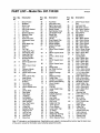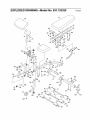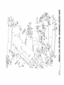
1
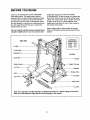
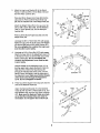
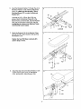
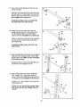
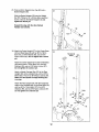
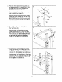
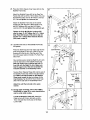
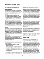
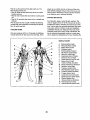
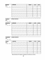
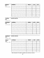
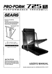
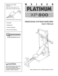
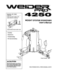
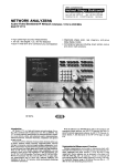
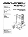
Model No, 831.153320
Serial No.
Write the serial number in the
space above for reference.
WEIGHT BENCH EXERCISER
User's Manual
Serial Number Decal (under seat)
• Assembly
• Adjustments
• Part List and Drawing
Patent Pending
_CAUTION
Read all precautions and instructions in this manual before using
this equipmenL Save this manual for future reference.
Sears, Roebuck
and Co., Hoffman
Estates,
IL 60179
TABLE OF CONTENTS
WARNING DECAL PLACEMENT ..........................................................
IMPORTANT PRECAUTIONS .............................................................
BEFORE YOU BEGIN ...................................................................
ASSEMBLY ...........................................................................
ADJUSTMENTS ......................................................................
CABLE DIAGRAMS ....................................................................
TROUBLESHOOTING ..................................................................
EXERCISE GUIDELINES ...............................................................
ORDERING REPLACEMENT PARTS ................................................
FULL 90-DAY WARRANTY .......................................................
2
3
4
5
19
22
23
24
Back Cover
Back Cover
Note: A PART IDENTIFICATION CHART and a PART LIST/EXPLODED DRAWING is attached in the center of
this manual. Remove the PART IDENTIFICATION CHART and PART LIST/EXPLODED DRAWING before beginning assembly.
WARNING
DECAL PLACEMENT
The warning decals shown here have been
placed on the weight bench in the locations
shown. If a decal is missing or illegible,
please call toll-free t-800-999-3756, Monday
through Friday, 6 a.m. until 6 p.m. Mountain
Time, to order a free replacement decal.
Place the decal on the weight bench in the
location shown.
2
IMPORTANT
PRECAUTIONS
WARNING:
To reduce the risk of serious injury, read the following important precautions
before using the weight bench.
Read all instructions in this manual before
using the weight bench. Use the weight
bench only as described in this manual.
1.
12. The weight bench Is designed to support a
maximum user weight of 300 pounds and a
maximum total weight of 610 pounds. Do not
place more than 310 pounds on the barbell
guides or safety spotters. Do not place more
than 150 pounds on the weight carriage, the
leg lever, orthe curl bar. Note: The weight
bench does not include weights,
It is the responsibility of the owner to ensure
that all users of the weight bench are adequately informed of all precautions.
2.
The weight bench is intended for home use
only. Do not use the weight bench in any
commercial, rental, or institutional setting.
13. Always place an equal amount of weight on
each side of the weight carriage or barbell.
4.
Use the weight bench only on a level surface.
Cover the flour beneath the weight bench to
protect the floor,
14. Always secure the weights with the weight
clips when they are mounted on the weight
carriage or barbell.
5.
Make sure all parts are properly tightened
each time the weight bench is used. Replace
any worn parts immediately,
15. Always lower the weight carriage in a controlled manner; never let the weight carriage
drop.
6.
Keep children under 12 and pets away from
the weight bench at all times.
16. Always remove the lat bar when performing
an exercise that does not require the use of
the lat bar.
7.
Keep hands and feet away from moving pads.
8.
Always wear athletic shoes for foot protection while exercising.
9.
Make sure that the cables remain on the pulleys at all times. If the cables bind as you are
exercising, stop immediately and make sure
that the cables are on the pulleys.
3.
10. Always
height.
17. Always move your bench out of the way
when performing an exercise that does not
use the bench.
18. Use the curl bar only with the weight clips
provided with the bench.
19. Always make sure the backrest bracket is
fully engaged before using the backrest.
set both safety spotters at the same
20. If you feel pain or dizziness at any time while
exercising, stop immediately and begin cooling down.
11. Make sure that the set screws attaching the
Olympic weight adapters are properly tightened each time the adapters are used.
WARNING:
Before beginning this or any exercise program, consult your physician. This
is especially important for persons over the age of 35 or persons with pre-existing health problems.
Read all instructions before using. Sears assumes no responsibility for personal injury or property
damage sustained by or through the use of this product.
3
BEFORE YOU BEGIN
Thank you for selecting the versatile PROFORM ®
C840 weight bench. The weight bench offers an
impressive array of weight stations designed to develop every major muscle group of the body. Whether
your goal is to tone your body, build dramatic muscle
size and strength, or improve your cardiovascular system, the weight bench will help you to achieve the
specific results you want.
For your benefit, read this manual carefully before
using the weight bench. If you have questionsafter
reading this manual, call 1-800-4-MY-HOME ®
(1-800-469-4663). To help us assist you, please note
the product model number and serial number before
calling. The model number is 831.153320. The sedal
number can be found on a decal attached to the
weight bench (see the front cover of this manual for
the location of the decal).
Before reading further, please review the drawing
below and familiarize yourself with the parts that are
labeled.
ASSEMBLED
DIMENSIONS:
Height: 84 in.
Width: 84 in.
Length: 97 in.
Right Side
Lat Bal
Locking Bar
ButterflyArm
Left Side
Guide Bar
Barbell
Safety Spotter
jht Carriage
Curl Pad
Backrest
Seat
Storage Tube
Leg
Foot Plate
Ankle Strap
Curl Bar
Note: The "right side" and the "left side" are determined relative to a person sitting on the bench;
they do not correspond to right and left on the drawings in the manual,
4
ASSEMBLY
• Place all parts in a cleared area and remove the
packing materials. Do not dispose of the packing
materials until assembly is completed.
Make Things Easier for Yourself
This manual is designed to ensure that the
weight bench can be assembled successfully
by anyone, Most people find that by setting
aside plenty of time. assembly will go smoothly,
The following tools (not included) are required
for assembly:
• Two adjustable wrenches
Before beginning assembly, carefully read the
following information and instructions:
• One rubber mallet
• One standard screwdriver
• Assembly requires two people.
• One Phillips screwdriver
• For help identih/ina smafl Darts. use the PART
IDENTIFICATION CHART.
• Lubricant, such as grease or petroleum jelly,
and soapy water.
• Tighten all parts as you assemble them, unless
instructedto do otherwise.
Assembly will be more convenient if you have a
socket set, a set of open-end or closed-end
wrenches, or a set of ratchet wrenches.
• As you assemble the weight bench, make sure all
parts are oriented as shown in the drawings.
1.
Before _inningi
make sure you understand the information in the box above.
NOte: Some parts described in the assembiy steps may be pre-assambled,
Press a Notched Square Inner Cap (21) into the
end of the Bench Frame (1). Attach a Base Cap
(47) to the Stabilizer (2) with an M4 x 16mm
Screw (107) and an M10 x 25mm Screw (121).
Attach another Base Cap to the Stabilizer in
the same manner,
97
111
121-
Attach the Stabilizer (2) to the Bench Frame (1)
with two M10 x 92ram Carriage Bolts (111) and
two M10 Nylon Locknuts (97). Attach the
Stabilizer to the Bench Frame with two M10 x
68mm Bolts (113), two M10 Washers (99), and
two M10 Nylon Locknuts. Do not tighten the
Locknuts yet.
2,
2
113.
Press a Thin Notched Square Inner Cap (135) into
the bottom of the Bench Leg (3). Attach the Small
Base Cap (13) to the Bench Leg with an M4 x
16mm Screw (107).
Attach the Bench Leg (3) to the Bench Frame (1)
with two M10 x 68mm Bolts (113), two M10
Washers (99), and two M10 Nylon Locknuts (97).
13
107 --_
5
3.
Attach the Leg Lever Bracket (5) to the Bench
Frame (1) with two M10 x 81mm Bolts (122) and
two M10 Nylon Locknuts (97).
Press two 50mm Square Inner Caps (22) intothe
Leg Lever (4). Press a 25mm Round Inner Cap
(26) into the indicated end of the Weight Tube (25).
Attach the Weight Tube (25) to the Leg Lever (4)
with an M8 x 63mm Bolt (106), two M8 Washers
(100), a 13ram Spacer (30), and an M8 Nylon
Locknut (96).
Press a 25mm Round Angled Cap (62) onto the
Weight Tube (25).
Lubricate the M10 x 73ram Bolt (115) with grease.
Attach the Leg Lever (4) to the Leg Lever Bracket
(5) with the Bolt end an M10 Nylon Locknut (97).
Do not overtighten the Locknut; the Leg Lever
must be able to pivot easily.
4,
Lubricate an M10 x 81mm Bolt (122) with grease.
Attach the lower hole in the Adjustment Lever (11)
to the Bench Frame (1) with the Bolt and an M10
Nylon Locknut (97). Do not overtighten the
Locknut; the Adjustment Lever must be able
to pivot easily.
Hold the handle on the Adjustment Lever (11) so
that the upper hole is above the Bench Frame (1).
Slide the M10 x 65mm Flat Head Screw (27)
through the indicated side of the Lever, over the
Bench Frame, and tighten it into the other side of
the Adjustment Lever. Make sure that the threads
of the Screw show through the Adjustment
Lever. Do not overtighten the Screw.
5.
Press four 25mm Square Inner Caps (31) into the
ends of the Backrest Tubes (8).
Attach the Backrest Bracket (7) to the Backrest
Tubes (8) with four M10 x 45mm Bolts (112), four
M10 Washers (99), and four M10 Nylon Locknuts
(97). Make sure the Backrest Tubes are oriented so that the indicated holes are closer to
the bottom. Do not tighten the Locknuts yet.
4
1
Insert the Backrest Bracket (7) through the slot in
the Bench Frame (1) and under the Adjustment
Lever (11). Make sure that the M10 x 72mm
Flat Head Screw (27) is under the Backrest
Bracket arm.
8
99
27
Lubricate an M10 x 155mm Bolt (109) with
grease. Attach the Backrest Tubes (8) to the
Bench Frame (1) with the Bolt, two M10 Washers
(99), and an M10 Nylon Locknut (97). Do not
overtighten the Locknut; the Backrest Tubes
must be able to pivot easily,
7
Attach the Backrest (14) to the Backrest Tubes
(8) with four M6 x 38mm Screws (102) and four
M6 Washers (101).
7
14
Tighten the four MIO Nylon Locknuts (97)
used in steps 1 and 5.
8,
Attach the Seat (15) to the Bench Frame (1) with
an M6 x 63mm Screw (103), an M6 Washer
(101), and two M6 x 16mm Screws (104).
8
7
11
Lubricate
9.
Slide the Thick Pad Tube (10) into the hole in the
Leg Lever Bracket (5). Wet both sides of the Pad
Tube with soapy water. Slide two Small Foam
Pads (18) onto the Tube as shown. Press two
Small Pad Caps (20) into the Pad Tube.
Slide a Pad Tube (9) into a hole in the Leg Lever
(4). Wet both sides of the Pad Tube with soapy
water. Slide two Large Foam Pads (17) onto the
Pad Tube as shown. Press two Large Pad Caps
(19) into the Pad Tube. Repeat with the other
Pad Tube.
9
20
19
17
10
17
10. Attach the Curl Pad (16) to the Curl Post (6) with
two M6 x 16mm Screws (104).
19
10
104
11. Press a Round Angled Bushing (75) into a Rack
Foot (46).
11
r
Attach a Guide Bar (41) to the Rack Foot (46)
with an M10 x 50mm Screw (108) and an M10
Washer (99).
-133
Attach the Right Upright (133), which has numbers on the indicated side, to the Rack Foot (46)
with two M10 x 68ram Bolts (113), four M10
Washers (99), and two M 10 Nylon Locknuts (97).
Make sure the Bolts are inserted from the side
shown.
Do not tighten
the Locknuts
yet,
Repeat this step with the Left Upright (36 [not
shown]), Guide Bar (41), Rack Foot (46), and
Round Angled Bushing (75). Insert the M10 x
68mm Bolts (113) from the other side.
99
1084
18
20
12.See
the inset drawing. Attach the Large Base
Cap (117) to the Rear Base (33) with an M4 x
16mm Screw (107) and an M8 x 16mrn Screw
(98).
!12
7
33
Attach the Rear Base (33) to the Center Base
(32) with two M10 x 78mm Bolts (110), two M10
Washers (99), and two M10 Nylon Locknuts (97).
Do not tighten the Locknuts yet.
107
32
Set the Center Base (32) inside of the Foot Plate
(48). Attach the Foot Plate to the Center Base
with two M10 x 68mm Bolts (113), two M10
Washers (99), and two M10 Nylon Locknuts (97).
Do not tighten the Locknuts yet.
110
33
99_
97
99 _
"113
13. Press two 48mm Tapered Inner Caps (63) and a
51mm x 76mm Inner Cap (64) into the Storage
Leg (45).
13
Attach the Base Cap (47) to the Left Base (35)
with an M4 x 16mm Screw (107) and an M10 x
19mm Screw (118).
Orient the Storage Leg (45) so that the longer
side of the plate is in the indicated position.
Attach the Storage Leg to the Left Base (35) with
two M10 x 92mm Carriage Bolts (111) and two
M10 Nylon Locknuts (97).
107
35
111
14. Attach the Left Base (35) to the Center Base (32)
with three M10 x 68mm Bolts (113), three M10
Washers (99), and two M10 Nylon Locknuts (97).
Do not tighten the Locknuts yet.
99
113
99
9
113
15. Press a 32mm Square Inner Cap (66) into the
Right Base (34). Attach a Base Cap (47) to the
Right Base with an M4 x 16mm Screw (107) and
an M10 x 19mm Screw (118).
15
47
113 66
Attach the Right Base (34) to the Center Base
(32) with three M10 x 68mm Bolts (113), three
M10 Washers (99), and two M10 Nylon Locknuts
(97). Do not tighten the Locknuts yet.
34
16. Using a rubber mallet, tap the left Rack Foot (46)
into the Left Base (35). Attach the Rack Foot to
the Left Base with two M10 x 68mm Bolts (113),
four M10 Washers (99), and two M10 Nylon
Locknuts (97). Do not tighten the Locknuts yet,
1o7
!
16
Attach the other Rack Foot (not shown) to the
Right Base (not shown) in the same manner.
17. Attach the Right Spotter Hook (53) to a Safety
Spotter (52) with an M8 x 12mm Shoulder Bolt
(131) and an M8 Nylon Locknut (96). Make sure
the bolt head is on the same side as the handle.
17
Handle
96
Slide the Safety Spotter (52) onto the right Guide
Bar (41) and engage the Right Spotter Hook (53)
into an adjustment hole near the bottom of the
Right Upright (133).
53_
_//
131
52_
g6
52_131
41_
Assemble the Left Spotter Hook (54) and a
Safety Spotter (52) in the same manner.
Always set both Safety Spotters (52) at the
same height.
" --133
/ Adjustment Hole
18
18. Identify the Left and Right Barbell Gliders (51,
123) by the position of the screw holes.
Screw_
Slide each Barbell Glider (51,123) onto the
Guide Bar (41) next to the indicated Upright (36,
133). Make sure the Barbell Gliders are oriented as shown.
Hole
51 -- "_Screw
_
_"123
Hole
414
(
J/2
10
41--i/_
133
_-36
jl/j
19. Press a Round Joint Bushing (74) intothe Left
Frame Joint (49).
Attach the Top Frame (40) to the Left Frame Joint
(49) with two M10 x 91mm Bolts (116), four M10
Washers (99), and two M10 Nylon Locknuts (97).
Do not tighten the Locknuts yet.
1_
99
97
Assemble the Right Frame Joint (50) to the
Top Frame (40) in the same manner.
6
20. Attach the Left Frame Joint (49) to the Left
Upright (36) with two M10 x 91mm Bolts (116),
four M10 Washers (99), and two M1O Nylon
Locknuts (97). Do not tighten the Locknuts yet.
74_@49
2O
Attach the Left Frame Joint (49) to the Guide Bar
(41) with an M10 x 50mm Screw (108) and an
MI0 Washer (99).
49
41
Assemble the Right Frame Joint (50) in the
same manner.
99
21. Slide the Weight Bar (55) through the Left Barbell
Glider (51), the Locking Bar (56), and the Right
Berbel_ Glider (123). Make sure the Locking Bar
is oriented as shown.
21
12
Engage the hooks on the LockingBar (56) into a
set of holes in the Uprights (36, 133).
56
36
55
22. Slide a Weight Stop (67) onto the Weight Bar
(55). Thread a 1/4" x 14mm Allen Head Set
Screw (119) into the Weight Stop and the hole in
the Weight Bar. Do not tighten the Screws yet.
Thread a 1/4" x 14mm Screw (119) into the Left
Barbell Glider (51).
55
Repeat this step with the Right Barbell Glider
(not shown) and the other Weight Stop (not
shown),
11
67
23. Press a 48mm Tapered Inner Cap (63) into a
BarbellAdapter (59).
23
Slide the Barbell Adapter (59) onto the Weight
Bar (55). Thread a 1/4" x 9.5mm Allen Head Set
Screw (120) into the Barbell Adapter. Do not
tighten the Screw yet.
55
Repeat this step with the other Barbell
Adapter (not shown).
59
63
24. Attach the Center Upright (37) to the Center Base
(32) and Rear Base (33) with an M10 x 78mm
Bolt (110), an M10 Washer (99), and an M10
Nylon Locknut (97). Do not tighten the Locknut
yet.
24
Attach the Center Upright (37) to the Center Base
(32) with an M10 x 75mm Bolt (127), two M10
Washers (99), and an M10 Nylon Locknut (97).
Do not tighten the Locknut yet.
Attach a Weight Carriage Stop (70) to the Rear
Upright (38), at the indicated hole, with an M10 x
88ram Bolt (114) and an M10 Nylon Locknut (97).
Make sure the Square Carriage Bushing (61)
is on top.
Attach the Rear Upright (38), with the hexagonal
holes on the indicated side, to the Rear Base (33)
with two M10 x 75mm Bolts (127), four M10
Washers (99), and two M10 Nylon Locknuts (97).
Do not tighten the Locknuts yet.
12
25. Press two 48mm Tapered Inner Caps (63) into
the Weight Carriage (71). Insert an MI0 x 19mm
Hex Head Bolt (132) intothe bracket on the
Weight Carriage from the side shown.
25
Orient the Weight Carriage (71) as shown and
slide it onto the Rear Upright (38).
Attach the Weight Carriage Stop (70) to the Rear
Upright (38), at the indicated hole, with an M10 x
88mm Bolt (114) and an M10 Nylon Locknut (97).
Make sure the Square Carriage Bushing (61)
is on the bottom.
26, Press a 60mm Square Inner Cap (65) into the
Rear Top Frame (39).
26
39
Attach the Rear Top Frame (39) to the Rear
Upright (38) with two M10 x 72mm Hex Head
Bolts (130), two M10 Washers (99), and two M10
Nylon Locknuts (97). Make sure the bolt heads
are set inside the hex holes in the Rear
Upright. Do not tighten the Looknuts yet.
27. Attach the Rear Top Frame (39) to the Center
Upright (37) with two M10 x 78mm Bolts (110),
two M10 Washers (99), and two M10 Nylon
Locknuts (97). Do not tighten the Locknuts yet.
!27
110
126
Attach the Rear Top Frame (39) to the Top Frame
(40) with two M10 x 127mm Bolts (126), four M10
Washers (99), and two M10 Nylon Locknuts (97).
Do not tighten the Locknuts yet.
4O
13
99
28. Press two 50mm Square Inner Caps (22) into the
Butterfly Frame (42).
28
110
99
Attach the Butterfly Frame (42) to the Rear Top
Frame (39) with two M10 x 78mm Bolts (110), two
M10 Washers (99), and two M10 Nylon Locknuts
(97). Do not tighten the Locknuts yet.
99
39
Attach the Butterfly Frame (42) to the Center
Upright (37) with two M10 x 68mm Bolts (113),
two M10 Washers (99), and two M10 Nylon
Locknuts (97). Do not tighten the Locknuts yet.
Tighten all of the M10 Nylon Locknuts (97)
used in steps 11-28. Tighten the 1/4" x 14mm
Allen Head Set Screws (119) used in step 22
and the 1/4" x 9.5mm Allen Head Set Screws
(120) used in step 23.
113
29. Lubricate both axles on the Butterfly Frame (42)
with grease.
99
22
29
Press two 50ram Square Inner Caps (22) into the
ends of the Right Fly Arm (43). Insert a Fly Arm
Bushing (92) into the Arm. Wet the end of the
Arm with soapy water and slide a Fly Foam Pad
(95) onto it.
Have another person slide the Right Fly Arm (43)
onto the right axle on the Butterfly Frame (42).
Note: Be careful not to confuse the Left Fly
Arm (44) with the Right Fly Arm. Make sure
that the upper end of the Arm is behind the
indicated bracket on the Butterfly Frame.
22
44
94
Tap two 25mm Retainer Rings (93) onto the axle of
the Butterfly Frame (42) with the included retainer
tool. Make sure that the teeth on the Retainer
Rings bend toward the tool, as shown in the
inset drawing. Tap the 25mm Round Outer Cap
(94) onto the right axle on the Butterfly Frame.
42_
/
93<
Attach the Left Fly Arm (44) in the same
manner.
Retainer _:==]
Too,
30. During cable assembly, refer to the CABLE
DIAGRAMS on page 22 for cable identification
and to verify cable routing.
3O
1129
Locate the Butterfly Cable (83). Attach the
Cable to the Left Fly Arm (44) with an M8 x
16mm Shoulder Bolt (129) and an M8 Nylon
Locknut (96).
"
44 JR\\
14
83
I
31. Wrap the Butterfly Cable (83) over a "V"-pulley
(89). Attach the "V"-puney and a Large Cable Trap
(88) to the Center Upright (37) with an M10 x
60ram Bolt (128) and an M1O Nylon Locknut (97).
Make sure the Cable Trap is oriented to hold
the Cable in the groove of the "V"-pulley.
31
88
128
32. Wrap the Butterfly Cable (83) under a 90mm
Pulley (90). Attach the Pulley to the Double "U"bracket (73) with an M10 x 45mm Bolt (112) and
an M10 Nylon Locknut (97).
33. Wrap the Butterfly Cable (83) over a =V"-pulley
(89). Attach the =V"-pulley and a Large Cable
Trap (88) to the Center Upright (37) with an M10
x 6Omm Bolt (128) and an M1O Nylon Locknut
(97). Make sure the Cable Trap is oriented to
hold the Cable in the groove of the "V"-pulley.
33
34. Attach the Butterfly Cable (83) to the Right Fly
Arm (43) with an M8 x 16mm Shoulder Bolt (129)
and an M8 Nylon Locknut (96).
34
128
83
15
35. Locate the Lat Cable (81). Route the Cable up
through the Rear Top Frame (39) and over a
90ram Pulley (90). Attach the Pulley inside the
Rear Top Frame with an M10 x 78mm Bolt (110),
two M10 Washers (99), two 17mm Spacers (86),
and an M10 Nylon Locknut (97).
35
90
110
36. Route the Let Cable (81) over a 90mm Pulley
(90) and down through the Rear Top Frame (39).
Attach the Pulley inside the Rear Top Frame with
an M10 x 78mm Bolt (110), two M10 Washers
(99), two 17mm Spacers (86), and an M10 Nylon
Locknut (97).
36
97
9O
39
99
86
99
110
37. Wrap the Lat Cable (81) under a 90mm Pulley
(90). Attach the Pulley and a Small Cable Trap
(125) to the indicated hole in the two Pulley
Plates (72) with an M10 x 45mm Bolt (112) and
an M10 Nylon Locknut (97). Make sure the
Cable Trap is turned to hold the Cable in the
groove of the Pulley,
38. Wrap the Lat Cable (81) over a 90mm Pulley
(90). Attach the Pulley inside the Rear Top Frame
(39) with an M10 x 78ram Bolt (110) and an MI0
Nylon Locknut (97).
38
39
81
39. Attach the Let Cable (81) to the M10 x 19mm Hex
Head Bolt (132) in the Weight Carriage (71) with
an M10 Nylon Locknut (97). Do not overtightan
the Locknut; the Cable must be able to pivot.
39
16
40. Locate the Low Cable (82). Route the eyelet
end of the Cable through the Center Upright (37)
and under a 90ram Pulley (90). Attach the Pulley
inside the Upright with an M10 x 75mm Bolt
(127), two M10 Washers (99), two 17ram Spacers
(86), and an M10 Nylon Locknut (97).
40
41. Route the Low Cable (82) over a 90mm Pulley
(90) as shown. Attach the Pulley to the Double
"U"-bracket (73) with an M10 x 45mm Bolt (112)
and an M1O Nylon Locknut (97).
41
42. Route the Low Cable (82) under a 90mm Pulley
(90) as shown. Attach the Pulley to the Rear
Base (33) with an M10 x 45mm Bolt (112) and an
M10 Nylon Locknut (97).
43. Route the Low Cable (82) over a 90ram Pulley
(90) as shown. Attach the Pulley and a Cable
Trap (125) to the second set of holes from the
bottom of the two Pulley Plates (72) with an M10
x 45mm Bolt (112) and an M10 Nylon Locknut
(97). Make sure the Cable Trap is oriented to
hold the Cable in the groove of the Pulley,
17
44. Attach the Low Cable (82) inside the Rear Base
(33) with an M10 x 75mm Bolt (127), two M10
Washers (99), two 27mm Spacers (87), and an
M10 Nylon Locknut (97). Do not overtighten the
Locknut; the Cable must be able to pivot easily.
44
97 99
87
82
99
45. Attach the Butterfly Backrest (80) to the Center
Upright (37) with two M6 x 72mm Screws (105)
and two M6 Washers (101).
46. Make sure that all parts have been properly tightened. The use of the remaining parts will be explained in
ADJUSTMENTS, beginning on the following page.
Before using the weight bench, pull each cable a few times to make sure that the cables move smoothly
over the pulleys. If one of the cables does not move smoothly, find and correct the problem. IMPORTANT:
the cables are not properly installed, they may be damaged when heavy weight is used. See the
CABLE DIAGRAMS on page 22 of this manual for proper cable routing. If there is any slack in the
cables, you will need to remove it by tightening the cables. See TROUBLESHOOTING
on page 23.
18
If
ADJUSTMENTS
This section explains how to adjust the weight bench. See the EXERCISE GUIDELINES on page 24 for important information about how to get the most benefit from your exercise program. Refer to the accompanying exercise guide to see the correct form for each exercise.
Make sure all parts are propedy tightenedeach time the weight bench is used. Replace any worn parts immediately. The weight bench can be cleaned with a damp cloth and a mild, non-abrasivedetergent.Do not use solvents.
ADJUSTING THE BACKREST
To adjust the position of the Backrest (14), hold the
upper end of the Backrest with one hand and lift the
Adjustment Lever (11) with the other hand, disengaging the Backrest Bracket (7). Raise or lower the
Backrest to the desired position. Lower the Adjustment Lever so that the M10 x 72mm Flat Head Screw
(27 [not shown]) engages one of the notches in the
Backrest Bracket.
14
WARNING:
Almys hold the
Backrest (14) securely before disengaging the
Backrest Bracket (7). Always make sure the
Backrest Bracket is fully engaged before using
the Backrest.
ATTACHING THE CURL POST
For some exercises, the Curl Post (6) must be
attached to the weight bench. Slide the Curl Post into
the Leg Lever Bracket (5). Align the adjustment holes
in the Curl Post with the adjustment hole in the Leg
Lever Bracket. "13ghtenthe Cud Knob (29) into the
adjustment hole in the Leg Lever Bracket. Fully tighten the Knob.
When not being used, the Cud Post (6) can be stored
on the tube on the Right Base (34) (see the inset
drawing].
5
19
USING THE OLYMPIC WEIGHT ADAPTER
Press a 48mm Round Inner Cap (23) into the Olympic
Adapter (24). Attach the Olympic Adapter to the
Weight Tube (25) with a 1/4" x 9.Smm Allen Head Set
Screw (120). Make sure that the Set Screw is in
the bottom of the Adapter.
25
24
Press a 48mm Round Inner Cap (23) into a Weight
Adapter (60). Attach the Weight Adapter to the Curl
Bar (76) with a 1/4" x 9.5mm Allen Head Set Screw
(120). Make sure that the Set Screw is in the bottom of the Adapter, Attach the other Weight
Adapter to the Curl Bar in the same manner,
2
23
120
60
76
120
ADDING WEIGHTS TO THE LEG LEVER
4
To use the Leg Lever (4), slide the desired weights
(not included) onto the Weight Tube (25). Secure the
weights with a Weight Clip (58 or 77 [not shown]).
Weights can be added to the Curl Bar (not shown) in
the same manner. Secure the weights to the Curl Bar
with two Weight Clips (53 or 77 [not shown]).
AWARNING:
oo.ot p,ace
more
58
than 150 pounds on the Weight Tube (25) or the
Curl Bar. (76).
See the inset drawing.
Storage Leg (45).
Weights
can be stored on the
ATTACHING THE ACCESSORIES
To use the Lat Bar (57), attach it to the Lat Cable (81)
with a Cable Clip (134). For some exercises, the
Chain (78) should be attached between the Lat Bar
and the Lat Cable with two Cable Clips (134). Adjust
the length of the Chain between the Lat Bar and
the Cable so that the Lat Bar is in the correct
starting position for the exercise to be performed.
The Ankle Strap (not shown) can be attached to the
Low Cable (not shown) in the same manner.
20
25
ADDING WEIGHTS TO THE BARBELL OR THE
WEIGHT CARRIAGE
To use the barbell or Weight Carriage (71), slide the
desired amount of weight (not included) onto the
Barbell Adapters (59) or Weight Carriage. Secure the
weights with the Large Weight Clips (77).
59
WARNING: Do.or.lacemore than
Weight
310 pounds on the barbell or t50 pounds on
the Weight Carriage (71). Always place the
same amount of weight on each side of the barbell or Weight Carriage. Always secure weights
with the Large Weight Clips [77).
71
USING THE LOCKING BAR
Before starting an exercise, position the Locking Bar
(56) in the correct position for the exercise.
To do this, stand in front of the rack and grip the
Locking Bar (56) with both hands. Turn the Locking
Bar until the two hooks disengage the slots in the Left
and Right Uprights (36 [not shown], 133). Raise or
lower the Locking Bar to a new position and turn it
until the hooks engage the slots in the Uprights.
123
56
MOVING THE SAFETY SPOTTERS
Before starting an exercise, position the Safety
Spotters (52) in the correct position for the exercise.
To move the Safety Spotters (52) to a new position,
grip the handles on the Spotter Hooks (53, 54 [not
shown]) and pull the hooks out of the slots in the
Uprights (36 [not shown], 133). Raise or lower the
Safety Spotters to new positions and pivot the hooks
back into the slots in the Uprights. Note: Always
start an exercise with the Safety Spotters positioned at the lowest point to which you want the
barbell to move during the exercise.
WARNING: Always
setboth
Safety
Spotters (52) at the same height.
21
CABLE DIAGRAMS
The cable diagrams below show the proper routing of the Lat Cable (81), the Low Cable (82), and the Butterfly
Cable (83). Use the diagram to make sure that the cables and the cable traps have been assembled correctly. If
the cables have not been correctly routed, the weight bench will not function proper/y and damage may occur.
The numbers show the correct route for each cable. Make sure that the cable traps do not touch or bind the
cables.
2
Butterfly Cable (83)
Length: 1.25m
5
_
4
2
Lat Cable (81)
Length:3.16m
4
Low Cable (82)
Length: 5.59m
3
22
TROUBLESHOOTING
Make sure all parts are properlytightened each time the weight bench is used. Replace any worn parts immediately. The weight bench can be cleaned using a damp cloth and mild non-abrasive detergent. Do not use solvents.
TIGHTENING THE CABLES
Woven cable, the type of cable used on the weight bench, can stretch slightly when it is first used. if there is
slack in the cables before resistance is felt, the cables should be tightened. Slack can be removed from the
cables in several ways:
See drawing 1. To tighten the cables, remove the
M10 Nylon Locknut (97) and the M10 x 45mm Bolt
(112) from the lower 9Omm Pulley (90), Cable Trap
(125), and the Pulley Plates (72). Reattach the Pulley
and the Cable Trap between a set of holes closer to
the center of the Pulley Plates with the Bolt and
Locknut. Make sure the Cable Trap is oriented to
hold the Low Cable (82) in the groove of the
Pulley,
97..._.!
_.72
9o-
,2
125
82-
See drawing 2. Additional slack can be removed
from the cables by tightening a cable into the M6
Nylon Locknut (124) inside a Cable End Clip (85). To
do this, pull the Clip Cover (84) back and use pliers to
tighten the Locknut. Replace the Cover.
124
1
Cable
\4
Do not overtighten the cables. If a cable slips off the pulleys repeatedly, it may have become twisted.
Remove the cable and re-install it. If the cables need to be replaced, see ORDERING REPLACEMENT
PARTS on the back cover of this manual,
23
EXERCISE GUIDELINES
THE FOUR BASIC TYPES OF WORKOUTS
PERSONALIZING YOUR EXERCISE PROGRAM
MUSCLE BUILDING
To increase the size and strength of your muscles,
push them close to their maximum capacity.Your muscles will continuallyadapt and grow as you progressively increase the intensity of your exercise. You can
adjust the intensity level of an individual exercise in
two ways:
• by changing the amount of resistance used
• by changing the number of repetitions or sets performed. (A "repetition" is one complete cycle of an
exercise, such as one sit-up. A "set" is a series of
repetitions.)
Determining the exact length of time for each workout,
as welt as the number of repetitions or sets completed,
is an individual matter. It is important to avoid overdoing it during the first few months of your exercise program. You should progress at your own pace and be
sensitive to your body's signals. If you experience pain
or dizziness at any time while exercising, stop immediately and begin cooling down. Find out what is wrong
before continuing. Remember that adequate rest and a
proper diet are important factors in any exercise program.
WARMING UP
The proper amount of resistance for each exercise
depends upon the individual user. You must gauge
your limits and select the amount of resistancethat is
right for you. Begin with 3 sets of 8 repetitionsfor each
exercise you perform. Rest for 3 minutes after each
set. When you can complete 3 sets of 12 repetitions
without difficulty,increase the amount of resistance.
Begin each workout with 5 to 10 minutesof stretching
and light exercise to warm up. Warming up prepares
your body for more strenuousexercise by increasing
circulation,raisingyour body temperature and delivering more oxygen to your muscles.
WORKING OUT
TONING
You can tone your muscles by pushing them to a moderate percentage of their capacity.Select a moderate
amount of resistance and increase the number of repetitions in each set. Complete as many sets of 15 to
20 repetitionsas possiblewithout discomfort.Rest for
1 minute after each set. Work your muscles by completing more sets rather than by using high amounts of
resistance.
Each workout should include 6 to 10 different exercises. Select exercises for every major muscle group,
emphasizing areas that you want to develop most. To
give balance and variety to your workouts, vary the
exercises from session to session.
Schedule your workoutsfor the time of day when your
energy level is the highest. Each workout should be
followed by at least one day of rest. Once you find the
schedule that is right for you, stick with it.
WEIGHT LOSS
To lose weight, use a low amount of resistance and
increase the number of repetitions in each set.
Exercise for 20 to 30 minutes, resting for a maximum
of 30 seconds between sets.
EXERCISE FORM
Maintaining proper form is an essential part of an
effective exercise program. This requiresmoving
through the full range of motion for each exercise, and
moving only the appropriate parts of the body.
Exercising in an uncontrolledmanner will leave you
feeling exhausted. On the exercise guide accompanying this manual you will find photographsshowingthe
correct form for several exercises, and a list of the
muscles affected. Refer to the muscle chart on the
next page to find the names of the muscles.
CROSS TRAINING
Cross training is an efficient way to get a complete and
well-balanced fitness program. An example of a balanced program is:
• Plan strength training workouts on Monday,
Wednesday, and Friday.
• Plan 20 to 30 minutes of aerobic exercise, such as
running on a treadmill or dding on an elliptical or
exercise bike, on Tuesday and Thursday.
• Rest from both strength training and aerobic exercise
for at least one full day each week to give your body
time to regenerate.
The combinationof strength training and aerobic exercise will reshape and strengthenyour body, plus develop your heart and lungs.
The repetitions in each set should be performed
smoothly and without pausing. The exertion stage of
each repetition should last about half as long as the
return stage. Proper breathing is important. Exhale
during the exertion stage of each repetition and inhale
during the return stroke. Never hold your breath.
24
Rest for a short period of time"after each set, The
ideal resting periods are:
• Rest for three minutes after each set for a muscle
building workout.
• Rest for one minute after each set for a toning workout.
• Rest for 30 seconds after each set for a weight loss
workout.
Plan to spend the first couple of weeks familiarizing
yourself with the equipment and learning the proper
form for each exercise.
slowly as you stretch and do not bounce. Ease into
each stretch gradually and go only as far as you can
without strain. Stretching at the end of each workout
is an effective way to increase flexibility.
STAYING MOTIVATED
For motivation, keep a record of each workout. The
chart on pages 26 and 27 of this manual can be photocopied and used to schedule and record your workouts. List the date, the exercises performed, the resistance used, and the numbers of sets and repetitions
completed. Record your weight and key body measurements at the end of every month. Remember, the
key to achieving the greatest results is to make exercise a regular and enjoyable part of your everyday life.
COOLING DOWN
End each workout with 5 to 10 minutes of stretching.
Include stretches for both your arms and legs. Move
MUSCLE CHART
A.
B.
C.
D.
E.
F.
G.
H.
I.
J.
K.
L.
M.
N.
O.
P.
Q.
R.
S.
T.
U.
V.
W.
X.
25
Sternomastoid (neck)
Pectoralis Major (chest)
Biceps (front of arm)
Obliques (waist)
Brachioradials (forearm)
Hip Flexors (upper thigh)
Abductor (outer thigh)
Quadriceps (front of thigh)
Sartorius (front of thigh)
TibialisAnterior (front of calf)
Soleus (front of calf)
Anterior Deltoid (shoulder)
RectusAbdominus (stomach)
Adductor (inner thigh)
Trapezius (upper back)
Rhomboideus (upper back)
Posterior Deltoid (shoulder)
Triceps (back of arm)
Latissimus Dorsi (mid back)
Spinae Erectors (lower back)
Gluteus Medius (hip)
Gluteus Maximus (buttocks)
Hamstring (back of leg)
Gastrocnemius (back of calf)
MONDAY
EXERCISE
WEIGHT
SETS
REPS
WEIGHT
SETS
REPS
WEIGHT
SETS
REPS
Date:
/
/
TUESDAY
AEROBIC EXERCISE
Date:
!
/
WEDNESDAY
EXERCISE
Date:
!
/
THURSDAY
AEROBIC EXERCISE
Date:
/
/
EXERCISE
FRIDAY
Date:
/
/
Make photocopies of this page forscheduling and recording your workouts.
26
MONDAY
EXERCISE
WEIGHT
SETS
REPS
WEIGHT
SETS
REPS
WEIGHT
SETS
REPS
Date:
!
!
AEROBIC EXERCISE
TUESDAY
Date:
I
!
WEDNESDAY
EXERCISE
Date:
!
I
THURSDAY
AEROBIC EXERCISE
Date:
!
!
FRIDAY
EXERCISE
Date:
/
!
Make photocopies of this page for scheduling and recording yourworkouts.
27
PART IDENTIFICATION
CHART
Refer to the drawings below to identify small parts used in assembly.The number in parentheses by each drawing is the key number of the part, from the PART LIST in the center of this manual. Important: Some parts may
have been pre-assembled for shipping purposes. If a part is not in the parts bag, check to see if it has
been pre-attached. If a part is missing, call toil-free 1-800-999-3756.
M 10 Nylon Locknut (97)
M8 x 12mm Shoulder
Bolt (131)
M10 Washer (99)
1/4" x 9.5mm Allen
Head Set Screw (120)
M8 Nylon Locknut (96)
M8 Washer (100)
M6 Nylon Locknut (124)
M6 Washer (101)
25mm Round Angled Cap (62)
25mm Square Inner Cap (31)
25mm Round Outer Cap (94)
25mm Retainer Ring (93)
25mm Round Inner Cap (26)
32mm Square Inner Cap (66)
I
M10 x 60mm Bolt (128)
M10 x 50mm Screw (108)
_.
M10 x 45ram
Bolt (112)
I
D
M6 x 38ram Screw
M10 x
(102)
D
M10 x 25ram
Screw
I
M8x63mmBolt(106)
_j
M6 x 63mm Screw (103)
65mm Flat
Head
Screw
(27)
itl
M10 x 68mm Bolt (113)
(121)
M6 x 72mm Screw (106)
M10 x 19ram Hex Head
M10 x 72mm Hex Head Bolt (130)
Bolt (132)
M10 x 73mm Bolt (115)
M10 x 19ram Screw
(118)
M10 x 75mm Bolt (t27)
M8 x 16ram Screw
(98)
M10 x 78mm Bolt (110)
M8 x 16ram Shoulder
Bolt (129)
M10 x 81mm Bolt (122)
D
M6 x 16mm Screw
(104)
c
i
M10 x 88mm Bolt (114)
0
M4 x 16ram Screw
(107)
114" x 14ram Screw
(119)
I
M10 x 91mm Bolt (116)
M10 x 92mm Carriage Bolt (111)
I
I
M10 x 127mm Bolt (126)
M10 x 155mm Bolt (109)
P
P
f
I II II III
J
,%
H_H,u
51mm x 76mm Inner Cap (64)
f
60mm Square Inner Cap (65)
J
50mm Square Inner Cap (22)
J
L
\
48ram Tappered Inner Cap (63)
48mm Round Inner Cap (23)
PART LIST--Model
Key Qty.
No.
1
2
3
4
5
6
7
8
9
10
11
12
13
14
15
16
17
18
19
20
21
1
1
1
1
1
1
1
2
2
1
1
3
1
1
1
1
4
2
4
2
1
22
8
23
3
24
25
26
1
1
3
27
1
28
2
29
30
31
1
1
4
32
33
34
35
36
37
38
39
40
41
42
43
44
45
46
47
1
1
1
1
1
1
1
1
1
2
1
1
1
1
2
4
Description
Bench Frame
Stabilizer
Bench Leg
Leg Lever
Leg Lever Bracket
Cud Post
Backrest Bracket
Backrest Tube
Pad Tube
Thick Pad Tube
Adjustment Lever
Grip
Small Base Cap
Backrest
Seat
Cud Pad
Large Foam Pad
Small Foam Pad
Large Pad Cap
Small Pad Cap
Notched Square
Inner Cap
5Omm Square Inner
Cap
48mm Round Inner
Cap
OlympicAdapter
Weight Tube
25mm Round Inner
Cap
M10 x 65mm Flat
Head Screw
Small Round
Bushing
Curl Knob
13mm Spacer
25mm Square Inner
Cap
Center Base
Rear Base
Right Base
Left Base
Left Upright
Center Upright
Rear Upright
Rear Top Frame
Top Frame
Guide Bar
Butterfly Frame
Right Fly Arm
Left Fly Arm
Storage Leg
Rack Foot
Base Cap
No. 831.153320
Key Qty.
No,
48
49
50
51
52
53
54
55
56
57
58
59
60
61
1
1
1
1
2
1
1
1
1
1
2
2
2
4
62
1
63
6
64
1
65
1
66
1
67
68
69
70
2
8
0
2
71
72
73
74
75
1
2
1
2
2
76
77
78
79
80
81
82
83
84
85
86
87
88
89
90
91
92
93
1
2
1
1
1
1
1
1
2
2
6
2
2
2
9
4
2
4
Description
Foot Plate
Left Frame Joint
Right Frame Joint
Left Barbell Glider
Safety Spotter
Right Spotter Hook
Left Spotter Hook
Weight Bar
LockingBar
Lat Bar
Small Weight Clip
BarbellAdapter
Weight Adapter
Square Carriage
Bushing
25mm Round Angled
Cap
48mm Tapered Inner
Cap
51mm x 76mm Inner
Cap
6gram Square Inner
Cap
32mm Square Inner
Cap
Weight Stop
Bar Slide Bushing
not used
Weight Carriage
Stop
Weight Carriage
Pulley Plate
Double "U"-bracket
Round Joint Bushing
RoundAngled
Bushing
Curl Bar
Large Weight Clips
Chain
Ankle Strap
Butterfly Backrest
Lat Cable
Low Cable
Butterfly Cable
Clip Cover
Cable End Clip
17mm Spacer
27mm Spacer
Large Cable Trap
"#"-pulley
90ram Pulley
Weight Bar Bushing
Fly Arm Bushing
25mm Retainer Ring
R O3A
Key Qty.
No.
94
2
95
96
97
98
99
100
101
102
103
104
105
106
107
108
109
110
111
2
5
70
1
83
2
7
4
1
4
2
1
6
4
1
10
4
112
113
114
115
116
117
118
119
120
9
22
2
1
8
1
2
4
5
121
122
123
124
125
126
127
128
129
2
3
1
2
2
2
5
2
2
130
2
131
2
132
1
133
134
135
1
2
1
#
#
#
#
1
1
1
3
Description
25mm Round Outer
Cap
Fly Foam Pad
M8 Nylon Locknut
M10 Nylon Locknut
M8 x 16mm Screw
M10 Washer
M8 Washer
M6 Washer
M6 x 38ram Screw
M6 x 63mm Screw
M6 x 16mm Screw
M6 x 72mm Screw
M8 x 63mm Bolt
M4 x 16mm Screw
M10 x 5Omm Screw
M1O x 155mm Bolt
M1Ox 78mm Bolt
M1Ox 92ram
Carriage Bolt
M10 x 45ram Bolt
M1Ox 68mm Bolt
M1Ox 88mm Bolt
M10 x 73mm Bolt
M10 x 91ram Bolt
Large Base Cap
M10 x 19mm Screw
1/4" x 14mm Screw
1/4" x 9.5mm Allen
Head Set Screw
M10 x 25mm Screw
M10 x 81mm Bolt
Right Barbell Glider
M6 Nylon Locknut
Small Cable Trap
M10 x 127mm Bolt
M10 x 75mm Bolt
M10 x 60mm Bolt
M8 x 16mm
Shoulder Bolt
M10 x 72mm Hex
Head Bolt
M8 x 12mm
Shoulder Bolt
M10 x 19mm Hex
Head Bolt
Right Upright
Cable Clip
Thin Notched
Square Inner Cap
User's Manual
Exercise Guide
Grease Pack
Allen Wrench
Note: "#" indicates a non-illustrated part, Specifications are subject to change without notice. See the back cover
of the user's manual for information about ordering replacement parts.
EXPLODED
DRAWING--Model
No. 831.153320
R11O3A
14
31
112
101
97
102
104
112
31
15
.-i
t
102
5
97,,
-_
29
115
113
il;
4
97
27
122
21
47
104
113
1O6
12
19
120
47
19
18
107
135
i
i
107_,
19
20
19
121
110
_26
66
8
108
5O
99
97
110
88
40
99
116
99
88
125
128
134
72
99
99
95
63
59
z
t
87
90
67
t
11o
120
11g
_113
97
66
23
64
99
.-t.
11#*
110
68
45
131
97
99
107
68
97
97
34
67
7y
0
77
76
113
.-t
O
Your Home
For repair - in your home - of all major brand appliances, lawn and garden equipment,
or heating and cooling systems, no matter who made it, no matter who sold it!
For the replacement parts, accessories, and user's manuals that you need to do-it-yourself.......
7_i_i_7
_iiiiiiill
For Sears professional installation of home appliances
and items like garage door openers and water heaters.
_........
1 ....
800 4 MY HOME
_;';':,
(1-800 -469 -4663)
........
www.sears.com
®
_i
An
ytime,
ii!iiiii
_!_i_!
;!!!
day or n ight
.........
,m;m
(U .S.A. and Canada)
.......
www,sears.ca
!_!_,_
........
Our Home
.........,_,_,_,,,,
......
.......
........
ii!iiii!_!
For repair of carry-in products like vacuums, lawn equipment,
and electronics i call o r go on- line fo r the location of your nee r est
Sears Parts and Repair Center
..........
......
?_i;71;i!
1- 800 - 488 - 1222
_ili
i;i
........
An ytime, day or n ight(U.S.A.
www.sears.com
.....
........
;_,
......
......
on ly)
;_;;_
.......
....
ii!Tii
_:;t
iiiili
!iii: i
.......
To pumhase a protection agreement (U S A )
_
iiii!i!
or maintenance agreement (Canada) on a product serviced by Sears:
'i!r........
ili!:iiii:
........
.........
1-800-827-6655
...............
(U.S.A.)
1-800-361-6665
:!iti_
(Canada)
iiii!ili
I
i17!i!
:_
Para pedir servicio de reparacidn a domicilio I y pare ordenar piezas:
........
_
1 888-SU HOGAR s_ (1 888-7846427)
....
.........
_i!i!i}i)iii_"
® Registered Trademark / TMTrademark / s_ Service Mark of Sears, Roebuck and Co.
® Marca Registrada / TMMarca de Fdbrica / SMMarca de Se_icio de Sears, Roebuck and Co.
-%
F
FULL 90-DAY WARRANTY
For 90 days from the date of purchase, if failure occurs due to defect in material or workmanship in this
WEIGHT BENCH EXERCISER, contact the nearest Sears Service Center throughout the United States
and Sears will repair or replace the WEIGHT BENCH EXERCISER, free of charge.
This warranty does not apply when the WEIGHT BENCH EXERCISER is used commerciallyor for
rental purposes.
This warranty gives you specific legal rights, and you may also have other rights which vary from state
to state.
Sears, Roebuck and Co., Dept 817WA, Hoffman Estates, IL 60179
J
Part No. 199800 R1103A
Printed in China © 2003 Seam, Roebuck and Co.