1
Freescale Semiconductor, Inc.
Application Note
AN2599/D
Rev. 1, 2/2004
Freescale Semiconductor, Inc...
Generic LIN Driver for
MC68HC908QY4
By: Jenny Felvus and Davor Bogavac
Motorola, East Kilbride
Overview
This application note describes a generic slave LIN driver that was developed
for the MC68HC908QY4 microcontroller unit (MCU). It is the driver that comes
with the LIN Kits software, which is described in Motorola document AN2573/D.
The complete documentation and software for the LIN Kits evaluation board,
including this driver, can be downloaded from the Motorola LIN website:
www.motorola.com/semiconductors/LIN.
LIN (local interconnect network) is a low-cost communication protocol often
used in automotive applications that do not require the bandwidth and
versatility of CAN. The LIN bus uses a single data wire and can communicate
at speeds up to 20 kbps. A LIN network has a single master and multiple
slaves, so no bus arbitration is required.
The driver was developed from the LIN Specification Package, rev. 1.3 and has
been evaluated at both 9.6 kbps and 19.2 kbps.
This LIN driver can handle auto baud-detection up to 20 kbps and synchronizes
automatically without pre-trimming the on-chip RC oscillator. The driver can
detect bit and checksum errors. It comes with an API, which is described in this
document and enables easier use.
The driver uses bit-banging, a method that uses general-purpose I/O lines to
emulate a serial port. Transmission is done by software toggling the data line
in the proper sequence. Reception is done by using the output compare
function to periodically sample the bus state.
NOTE:
With the exception of mask set errata documents, if any other Motorola
document contains information that conflicts with the information in the device
data sheet, the data sheet should be considered to have the most current and
correct data.
This product incorporates SuperFlash technology licensed from SST.
© Freescale Semiconductor, Inc., 2004. All rights reserved.
For More Information On This Product,
Go to: www.freescale.com
© Motorola, Inc., 2004
Freescale Semiconductor, Inc.
AN2599/D
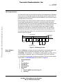
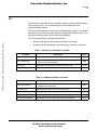
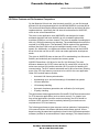
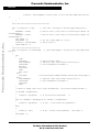
Hardware
The LIN Kits demo board consists of an MC68HC908QY4 MCU and a LIN
interface. The LIN interface consists of an MC33399 LIN transceiver and a 5-V
regulator (LT1121 chip). The board can be programmed using either the
RS-232 MON08 interface or a Cyclone/MultiLink tool.
Freescale Semiconductor, Inc...
The user may choose which GPIO port is used as the LIN transmit pin, but the
default configuration is port B, pin 2 (PTB2). The LIN receive pin must be
port A, pin 1 (PTA1) because this is the timer channel 1 pin.
The board requires one jumper (J3) for running an application, and three
jumpers (J2, J4, and J5) if using the RS-232 MON08 interface to
program/debug. The jumper J2 is not required when using a MultiLink/Cyclone
tool to program.
~12 V
VBat
8
1
LT1121
5V
3
5
100 kΩ
47 kΩ
100 kΩ
2.2 kΩ
1 kΩ
100 nF
J2
(MONITOR
MODE)
27 kΩ
LIN
6
7
VSup
8
INH
LIN
MC33399
3 WAKE
10 kΩ
J4
13
5 V (DEBUG)
47 kΩ
12
RESET
B0
IRQ
RESET
3
PUSH-BUTTON
S1
9.1 V
ZENER
6
EN 2
Rx 1
Tx 4
GND
5
5
VDD
16
J3
15
B7
MC68HC908QY4
A1 (Rx)
14
B3
11
B4
10
B5
7
B6
B2 (Tx)
OSCILLATOR MODULE
8
(DEBUG)
OSC1
J5
VSS
4
1 kΩ 1 kΩ 1 kΩ 1 kΩ
GND
Figure 1. MC68HC908QY4 Schematic
Cyclone and MultiLink are registered trademarks of P&E Microcomputer Systems, Inc.
2
Generic LIN Driver for MC68HC908QY4
For More Information On This Product,
Go to: www.freescale.com
Freescale Semiconductor, Inc.
AN2599/D
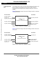
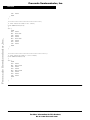
CodeWarrior Project
CodeWarrior Project
Freescale Semiconductor, Inc...
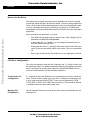
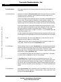
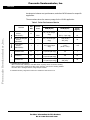
As mentioned, this driver is included in the LIN Kits demo software, which can
be downloaded free of charge from the Motorola LIN website. The driver comes
as a Metrowerks CodeWarrior 3.0 project (Sample.mcp). The project
structure can be seen in Figure 2:
Figure 2. CodeWarrior Project Structure
The LIN driver consists of five files:
•
LINdriver.c — contains the main driver code
•
LINapi.c — contains all the driver API functions
•
LINmsg.c — where all LIN message frames are defined
•
LINdriver.h — header file for the driver
•
Tx_Config.h — header file containing the transmission pin definitions
The driver also requires these standard files and libraries:
•
start08.c
•
MC68HC908QY4.h
•
MC68HC908QY4.c
•
ansi.lib
•
vector.c — defines the interrupt vectors needed for the project
•
hc08qy4.prm — defines memory locations (ROM and RAM) in the MCU
Metrowerks and CodeWarrior are registered trademarks of Metrowerks, Inc., a wholly owned subsidiary of Motorola, Inc.
Generic LIN Driver for MC68HC908QY4
For More Information On This Product,
Go to: www.freescale.com
3
Freescale Semiconductor, Inc.
AN2599/D
How to Use the Driver
The easiest way to begin developing a new application is to use the sample
project that comes with the LIN Kits demo board. To do this, simply replace the
slave.c file from the LIN Kits sample application with your own application code.
You can also begin developing by creating a new project in a CodeWarrior
development environment and adding the five LIN driver files from the sample
application.
Freescale Semiconductor, Inc...
When creating a new application, you must:
•
First define the messages that you want to use (in the LINmsg.c file) as
described in LIN Driver Configuration.
•
In the header file, Tx_Config.h, you can change the transmission pin
from the default setting (PTB2).
•
Ensure that the vectors ( _Startup() uses vector 0 and TimA1ISR() uses
vector 5) are set up correctly, either in the vector.c file or in a parameter
file.
•
Don’t forget to #include the file LINdriver.h in your application code file.
LIN Driver Configuration
The driver configuration uses two files, LINmsg.c and Tx_Config.h, which can
be edited by the user. For detailed information about the configuration files and
how to use the driver, see the user manual for the MC68HC908QY4 driver,
which is included with the LIN Kits software installation.
Transmission Pin
Configuration
Tx_Config.h contains the definition of the transmission pin that the LIN driver
uses. This file must be edited only if you want to change the transmission pin
to a pin other than the default (PTB2). There are four parameters (TxPIN,
TxPIN_DDR, TxPORT, and TXBIT) that must be set. They should be defined
in symbolic format and must match each other.
Message File
Configuration
All LIN message frames to be used by the slave node must be defined in the
LINmsg.c file.
4
Generic LIN Driver for MC68HC908QY4
For More Information On This Product,
Go to: www.freescale.com
Freescale Semiconductor, Inc.
AN2599/D
LIN Driver Configuration
Define one array for each message frame that either requires a response or
must be received. When defining, it is good practice to include the frame ID in
the name (for example, “Message0xID”, where ID is the message identifier in
hexadecimal with the parity bits included). The data field can be 2, 4, or 8 bytes
long. The array size should equal the number of data bytes (for example,
“U8 volatile Message0xD8[2];”).
Arrays
After all messages that will be recognized by the node have been defined, you
must include them in a number of arrays. The order of the messages must be
consistent in all arrays. The following three arrays are required:
Freescale Semiconductor, Inc...
Message Buffers
•
MessagePointerTbl[] — Consists of pointers to all message buffers
defined according to Message Buffers.
Example: U8 volatile * MessagePointerTbl[] =
{Message0xD8, Message0x99,…};
•
IdTbl[] — Contains all IDs relevant to this node. It is very important that
the ID includes the parity bits. The order of the messages must be the
same as in MessagePointerTbl[] and MessageCountTbl[]
Example: U8 const near IdTbl[] = {0xD8, 0x99,…};
•
MessageCountTbl[] — Defines the length (in bytes) of the message data
for each message and shows whether the message should be sent or
received by the slave. The least significant half-byte (LSHB) is the
number of data bytes in the frame plus the checksum). For example, for
Message0x20[4] then LSHB= 5
The most significant half-byte (MSHB) should be set to 1 for master
tasks (slave receiving) or 0 for slave tasks (slave sending). It could also
be set to F (send when updated), which means that the message is only
sent if it has been updated since it was last read/written.
Example: U8 volatile near MessageCountTbl[] = {0x03,
0xF5, 0x19,…};
This example shows that the message with ID 0xD8 (in IdTbl above) is
2 bytes long (plus checksum) and defined for sending.
Please remember that the order of the messages must be consistent in all
previous tables. All arrays (except message buffers) must be defined as
described in the bullets above.
NOTE:
The data type U8 frequently used in the driver and its API is defined as an
unsigned 8-bit number. For this compiler, U8 is defined as “unsigned char”.
Generic LIN Driver for MC68HC908QY4
For More Information On This Product,
Go to: www.freescale.com
5
Freescale Semiconductor, Inc.
AN2599/D
Freescale Semiconductor, Inc...
Special
Considerations
6
•
The driver uses only timer channel 1. Using channel 0 for other
application functions is permitted, but modifying the timer modulus
register is prohibited because the driver assumes that the overflow value
of the timer is set to 0xFFFF.
•
No interrupt service routine (ISR) is allowed except the one used by the
LIN driver during communication. This is because the Tx and Rx pins are
software controlled and must have a predictable latency for the ISR
response.
•
The OSCTRIM register can be set to any value, but it is recommended
that it be set to 0. This is to trim the oscillator to its maximum speed,
which guarantees the highest possible bus speed. This setting enables
the application to take full advantage of the auto baud-detection feature.
•
Manipulating the Tx pin outside of the driver will most likely cause a bit
error (and aborted transmission). Special care should be taken when
using read-modify-write instruction sequences (such as LDA/STA
instruction combinations) on the port that contains the Tx pin because
this could write the wrong value if a LIN interrupt occurs between the two
instructions. Either disable interrupt while using read-modify-write (not
recommended) or use instructions that you know will compile to BSET
or BCLR.
•
The Rx pin (PTA1) is hardware-protected from manipulation because it
is set as an input capture.
•
If using MON08 tools for debugging, do not manipulate pin PTA0
because that would disturb communication with the tool.
•
When updating send or receive variables larger than 8 bits in an 8-bit
MCU, special considerations must be taken to guarantee atomic
operation. The normal approach is to inhibit interrupts while updating the
8-bit+ variable. This approach can be used, but it is highly recommended
to update only one variable at a time. Also, the interrupt should be
enabled between the updates. Observing these recommendations
ensures that communication timing will not be disturbed. (When
updating 8 bits or less, atomic operation at the frame level is guaranteed
because frame data is copied to/from the frame buffer inside the ISR.
Generic LIN Driver for MC68HC908QY4
For More Information On This Product,
Go to: www.freescale.com
Freescale Semiconductor, Inc.
AN2599/D
LIN Communication
LIN Communication
Freescale Semiconductor, Inc...
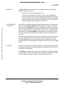
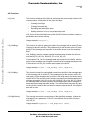
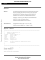
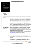
LIN information is sent on the LIN bus in the form of message frames. Message
frames can be of selectable length, but they always have the same format. A
message frame has from 0 to 8 bytes of data in addition to the 3 bytes of control
and data security information.
Each message frame starts with the master sending out a synchronization
break signal (synchbreak field), followed by a synchronization field and a
message identifier field. The slave then responds with the data field (which can
be from 0 to 8 bytes) and then the checksum field. The synchbreak field
identifies the beginning of a new message frame and provides a regular
opportunity for the slave to synchronize on the bus clock. The synch field
contains the information for the clock synchronization and is always 0x55.
An acknowledgment procedure for a correctly received LIN message is not
defined in the LIN protocol.
MESSAGE FRAME
HEADER
SYNCH
BREAK
SYNCH
FIELD
INTER-FRAME
SPACE
OR BREAK
RESPONSE
IDENT
FIELD
DATA
FIELD
DATA
FIELD
DATA
FIELD
IN-FRAME
RESPONSE SPACE
DATA CHECKSUM
FIELD
FIELD
INTER-BYTE
SPACE
Figure 3. LIN Message Frame
Driver Software
Overview
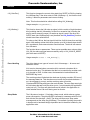
The file LINdriver.c contains the main functionality for running the driver. All
LIN communication activities are handled in the timer channel 1 ISR
(TimA1ISR). Timer channel 1 is configured for input capture, so when activity
on the LIN bus is detected, there is an interrupt and TimA1ISR is entered.
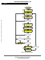
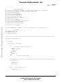
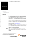
In TimA1ISR, the driver goes through several states. The flow of these states
is described in TimA1ISR States and illustrated in Figure 4.
1.
2.
3.
4.
5.
6.
7.
Unsynchronized
Idle
PossibleSync
SyncBreak
Synchronized
ReceiveID
Either
a. ReceivingWFS then Receiving OR
b. Sending
Generic LIN Driver for MC68HC908QY4
For More Information On This Product,
Go to: www.freescale.com
7
Freescale Semiconductor, Inc.
AN2599/D
TimA1ISR States
This section describes the different states that the driver enters when in
TimA1ISR.
1. Unsynchronized
The driver is initially in Unsynchronized state where the LIN bus is sampled.
The timer is used to measure the time between two falling edges and to
calculate how long one bit-time is.
Freescale Semiconductor, Inc...
The bit-time value is saved each time that it is calculated to be shorter than the
previous time. This procedure is repeated a certain number of times. The
number of repetitions (defined by the constant SyncBitCount) should be set
large enough so that at least two falling edges in the synch field are detected.
Worst case would be if measurement begins just before the ID byte. In this
case, three edges would appear in every byte. Adding the ID byte, checksum
byte, and maximum number of data bytes equals 10 bytes. In that case,
SyncBitCount must be set to 3 edges x 10 bytes + 3 (1 synchbreak edge and
2 synch byte edges) = 33.
So, after repeating the sampling 33 times and always keeping the shortest time,
the accurate time corresponding to two bit-times should have been calculated.
2. Idle
After synchronizing, the driver enters Idle state. In this state, the timer will
trigger on the input capture of a falling edge.
In Idle state, the timer value is saved and the timer changes to trigger on a
rising edge. Then the driver enters PossibleSync state.
3. PossibleSync
The saved timer value is used in PossibleSync to calculate the pulse length
between a falling and a rising edge and to check if the pulse length is longer
than 11 bit-times. If the pulse length is longer than 11 bit-times, a valid
synchbreak is found. Therefore the timer is changed to trigger on a falling edge
and the driver enters SyncBreak state.
If no synchbreak was found (the pulse length is not longer than 11 bit-times),
the driver returns to Idle state to wait for a synchbreak.
4. SyncBreak
In SyncBreak state, several bit-times are calculated for later use. The
synchronization field, which is characterized by five falling edges within eight
bit-times (the data 0x55 inside a byte field), is used. To calculate and save
bit-time x 8, start at the synchronization field’s first falling edge and count four
edges. From this calculation, bit-time and bit-time x 1.5 can be calculated and
saved.
5. Synchronized
Next, Synchronized state is entered to wait for the start bit of the ID byte. The
timer changes to output compare 1.5 bit-times later—with no pin action—and
the driver enters ReceiveID state.
8
Generic LIN Driver for MC68HC908QY4
For More Information On This Product,
Go to: www.freescale.com
Freescale Semiconductor, Inc.
AN2599/D
LIN Communication
Freescale Semiconductor, Inc...
6. ReceiveID
7a. ReceivingWFS/
Receiving
In ReceiveID state, all 8 bits of the ID are caught, and the ID is checked to
determine what kind of ID it is.
•
If this ID is a sleep ID, the sleep flag is set
•
If this ID is not defined for this node, the driver returns to Idle state
•
If the ID is relevant, the routine must determine whether the ID instructs
the slave to either receive or send. Recall that the “send when updated”
option indicates that the ID should be ignored unless its message data
has been updated since the last time it was sent.
If the ID is for receiving, the timer is changed to input capture on a falling edge.
The driver enters ReceivingWFS state and waits for the start bit of the first
byte. Then, in Receiving state, the received data byte is stored in a temporary
buffer. (Only the 8 data bits in the byte field should be saved—not the start and
stop bits.) After each received byte, there is a check to see whether all bytes
are received. If not, ReceivingWFS is entered again to catch the start bit in the
next byte. The driver will switch between these two states until all bytes are
received.
When all bytes are received, the checksum is calculated and compared with the
received checksum to see whether the received data is correct. If not, the
ChecksumERROR flag is set. If all data is correct, the data is saved in the
message buffer, the message status is updated, and the driver returns to Idle
state.
7b. Sending
If the ID is for sending (or if the ID is defined for “send when updated” and the
message is updated), the message data and a calculation of the checksum will
be copied to a frame buffer.
In Sending state, all data bytes are sent, including start and stop bits. Bit errors
are dealt with if needed, the message status is updated, and the driver finally
returns to Idle state, where it waits for a synchbreak and a new ID.
Generic LIN Driver for MC68HC908QY4
For More Information On This Product,
Go to: www.freescale.com
9
Freescale Semiconductor, Inc.
AN2599/D
START TimA 1ISR()
Unsynchronized
1
Freescale Semiconductor, Inc...
CALCULATE BIT-TIME
2
Idle
WIATING FOR
FALLING EDGE BREAK PULSE
3
PossibleSync
WAITING FOR
RISING EDGE BREAK PULSE
NO
FOUND
SYNCHBREAK?
YES
4
SyncBreak
CALCULATE BIT-TIMES
FOR LATER USE
5
Synchronized
WAIT FOR START BIT OF ID BYTE
6
ReceiveID
NO
ID DEFINED?
YES
NO
YES
UPDATED?
YES
7b
SEND
Sending
ID
CONFIGURED
FOR “SEND WHEN
UPDATED”
?
NO
TYPE OF ID?
YES
RECEIVE
ReceivingWFS
NO
WAIT FOR START BIT
7a
Receiving
RECEIVE ONE BYTE
Figure 4. Interrupt Flow Chart
10
Generic LIN Driver for MC68HC908QY4
For More Information On This Product,
Go to: www.freescale.com
ALL DATA
RECEIVED?
Freescale Semiconductor, Inc.
AN2599/D
API
API
The API that comes with the driver makes it easier to interface with the driver.
When using the API, it is not necessary to know anything about the
communications protocol.
Freescale Semiconductor, Inc...
This section describes the functions and constants used in the API. For details
about the functions, see the user’s manual for the MC68HC908QY4 driver. The
manual is included in the LIN Kits software installation.
The API includes status constants that describe:
•
Status of the service calls (such as sending or receiving)
•
Status of individual messages (such as empty, updated, or overrun)
Table 1. LIN Service Call Status Constants
Constant
Description
Value
LIN_OK
Service call succeeded without any error
0x00
LIN_ INVALID_ID
Requested ID is defined for the node, but for the opposite
direction (sending/receiving)
0x80
LIN_NO_ID
Requested message ID is not defined for this node
0x7F
LIN_INVALID_MODE
Service could not be called in the current driver state
0x16
Table 2. LIN Message Status Constants
Constant
Description
Value
LIN_MSG_NODATA
Data buffer for this message is empty (data has not been
initialized or received yet)
0x01u
LIN_MSG_OK
Message data OK (not overrun and not empty)
0x10u
LIN_MSG_NOCHANGE
Message data has not changed since last read/written
0x02u
LIN_MSG_UPDATED
Message data has been updated
0x20u
LIN_MSG_OVERRUN
Message data has not been read and was overwritten
0x04u
Generic LIN Driver for MC68HC908QY4
For More Information On This Product,
Go to: www.freescale.com
11
Freescale Semiconductor, Inc.
AN2599/D
LIN Message Status
Flow
The message status is stored in the table called LinMsgStatus[]. When the LIN
driver is initialized, all messages have the status LIN_MSG_NODATA.
Message status will change when the message is being sent, received, or
updated.
Freescale Semiconductor, Inc...
Figure 5 illustrates the change of status after PutMsg() is called or a message
is received at a node
Previous Status
New Status
LIN_MSG_NODATA
LIN_MSG_OK
LIN_MSG_NOCHANGE
LIN_MSG_UPDATED
PutMsg() is called
OR
A message is received at the node
LIN_MSG_UPDATED
LIN_MSG_OVERRUN
LIN_MSG_OVERRUN
LIN_MSG_OVERRUN
(stays the same)
Figure 5. Status Change After PutMsg() is Called
Figure 6 illustrates the change of status after GetMsg() is called or data is sent
from a node.
Previous Status
New Status
LIN_MSG_UPDATED
LIN_MSG_OVERRUN
LIN_MSG_OK
GetMsg() is called
OR
Data is sent from the node
LIN_MSG_NODATA
LIN_MSG_NODATA
(stays the same)
LIN_MSG_NOCHANGE
LIN_MSG_OK
LIN_MSG_NOCHANGE
Figure 6. Status Change After GetMsg() is Called
12
Generic LIN Driver for MC68HC908QY4
For More Information On This Product,
Go to: www.freescale.com
Freescale Semiconductor, Inc.
AN2599/D
API
API Functions
Freescale Semiconductor, Inc...
LIN_Init()
This function initializes the LIN driver and makes the driver ready to detect LIN
communication. Initialization of the driver includes:
•
Clearing error flags
•
Clearing the sleep flag
•
Resetting and starting the timer
•
Setting the driver to be in Unsynchronized state
LIN_Init() must be called before any other LIN API function is called. It takes no
parameters and returns nothing.
Usage example: LIN_Init();
LIN_GetMsg()
This function is used for getting the data of the message with a certain ID and
copying its data into a buffer. The parameters for this function are the ID (with
parity) of the message and a pointer to the buffer where to put the message
data.
LIN_GetMsg() returns a status constant that describes whether the call was
successful (LIN_OK, LIN_INVALID_ID, or LIN_NO_ID).
If the status is LIN_OK, the message data was copied into the buffer, and the
status of the message was changed to show that the message has been read.
If the status is not LIN_OK, no data was copied to the buffer.
Usage example: status = LIN_GetMsg (0x99, MsgData);
LIN_PutMsg()
This function is used for copying data to send from a buffer to the message data
of the message with a certain ID. The parameters for this function are the ID
(with parity) of the message and a pointer to the buffer where the data to send
can be found. The function returns a status constant that indicates whether the
call was successful (LIN_OK) or not (LIN_INVALID_ID or LIN_NO_ID). When
the message data has been updated, the message status will be changed to
show that the message has been written. The call itself does not send any data
on the LIN bus, however the next time the master requests this ID, the updated
data will be sent.
Usage example: status = LIN_PutMsg (0x1A, MsgData);
LIN_MsgStatus()
The function returns the current status of the specified message. It takes the
message ID as a parameter. If the ID is not defined, the function will return
LIN_NO_ID.
Usage example: msgstatus = LIN_MsgStatus (0x1A);
Generic LIN Driver for MC68HC908QY4
For More Information On This Product,
Go to: www.freescale.com
13
Freescale Semiconductor, Inc.
AN2599/D
LIN_GotoRun()
This function changes the current driver state from SLEEP to RUN by clearing
the LINSleep flag. If the driver state is RUN (LINSleep = 0), the function does
nothing. It takes no parameters and returns nothing.
Note: This function should be called before calling LIN_Wakeup().
Usage example: LIN_GotoRun();
Freescale Semiconductor, Inc...
LIN_Wakeup()
This function issues the LIN wake-up signal, which consists of eight dominant
bits (including start bit) followed by at least four recessive bits (including the
stop bit and a recessive pause). No wake-up signal is sent if the driver is in
SLEEP state (the LINSleep flag is set) because the LIN_GotoRun() function
should have been called before.
To wake up the LIN bus, the bus signal is held low for 8 bit-times, then set high
again. After waiting at least 4 bit-times (can be up to 64 bit-times) there should
be a synchbreak, and communication should resume. The driver will resume
from Idle state.
The function takes no parameters. There are two possible return values, either
LIN_OK (the wake-up signal was successfully sent) or LIN_INVALID_MODE
(the driver state is SLEEP).
Usage example: status = LIN_Wakeup();
Error Handling
The driver detects two types of errors in the LIN message — bit errors and
checksum errors:
A bit error is detected when a recessive bit is sent and a dominant bit is
detected on the bus. This indicates that the bus is controlled by another node
or is shorted to GND. In either case, the transmission is aborted and the
BitERROR flag is set.
The receiving node will calculate the checksum by doing a modulo-256 sum of
the message data bits. This checksum must match the received checksum. If
not, the message is corrupt, and the receiving node will set the
ChecksumERROR flag and ignore the received data. The error flags are single
bit-field values that are set by the driver (set to 1) and cleared by the application
code (set to 0). The flags are global and can be polled in the application to
check whether there is an error during send or receive.
Sleep Mode
14
The LIN protocol version 1.3 includes a sleep mode, which reduces system
power consumption. The global SLEEP command is a message with ID=0x3C
and with the first data byte = 0x00. The driver will discover a sleep mode
message and set the sleep flag (LINSleep). The method of putting the module
in sleep mode is hardware/design dependent and is therefore handled by the
application code.
Generic LIN Driver for MC68HC908QY4
For More Information On This Product,
Go to: www.freescale.com
Freescale Semiconductor, Inc.
AN2599/D
LIN Driver Features and Performance Comparison
LIN Driver Features and Performance Comparison
Freescale Semiconductor, Inc...
On the Motorola LIN web site, http://motorola.com/LIN, you can find several
different LIN driver implementations for the MC68HC908QY4 and other MCUs.
This section will describe the difference between this driver and other LIN driver
implementations—specifically the LIN slave driver described in AN2503/D,
which is also a timer-based driver.
The driver in this application note (AN2599/D) was designed to handle
autobaud detection and have the ability to run a hardware pulse width
modulator (PWM) on one timer channel. The driver is capable of sending data
with only 1 bit-time between every data byte. The autobaud detection would be
required for a ROM device. The hardware PWM is required if the application
needs a jitter-free PWM, such as for backlight intensity control, DC motor
speed, etc. Additionally, one difference between this driver and the AN2503
driver is that this one has an API, which can make application development
easier.
The driver in AN2503/D does not have an API or autobauding, but offers more
flexibility and modularity and requires less memory space.
AN2633/D describes a LIN driver for the QL4 LIN Kit board. The main
difference between the QY/QT series and the QL series MCU is that the QL
series uses a slave LIN interface controller (SLIC) module for handling LIN
communication. The SLIC module automates many LIN bus functions, allowing
more of the CPU and memory resources to be used for the user application.
Other SLIC module features include:
•
Automatic LIN frame synchronization
•
Autobauding up to and well exceeding LIN standard bus speeds
•
LIN error detection
•
LIN message handling
•
Automatic checksum generation and verification (for both types)
•
ID parity checking
The performance data suggests that the QL4 and EY16 MCUs are better suited
for CPU-intensive applications (such as motor control). For simpler, less
time-critical applications (such as contact monitoring), the QY4 should be
sufficient. MCU selection must be made by balancing cost and resource
requirements of CPU and memory.
The following performance data compares various methods of implementing
LIN communications with different hardware and software options. All are
based on using the same basic application found in the LIN Kits demonstration
software (modified to accommodate an 8-byte message). This data allows the
Generic LIN Driver for MC68HC908QY4
For More Information On This Product,
Go to: www.freescale.com
15
Freescale Semiconductor, Inc.
AN2599/D
developer to balance cost, performance, and other MCU features for a specific
application.
These numbers show the memory usage for the LIN Kit application:
SLIC
ESCI
Freescale Semiconductor, Inc...
TIM08
Table 3. Driver Performance Metrics
Version
Std
API
Feature
Level
QY/QT bit-banged
drivers
AN2503/D(1)
N
QY/QT bit-banged
drivers
AN2599/D
Y
—
EY16 ESCI
drivers
AN2575/D(2)
Y
LINQL4-ASM
Driver Code Resource Required
ROM (Bytes)
Stack
(Bytes)
536 (+ 3 per msg)
22
836 (+ 3 per msg)
22
32 (+12 per 8 byte
msg)
1103 (driver)
487 (API)
35
—
19 (+1 per 8 byte
msg)
1130
(driver + API)
< 25
N
—
11
(+ 8 per 8 byte msg)
172
7
LINQL4-C
N
—
18
(+ 8 per 8 byte msg)
120
20
LINQL4-API
Y
—
32
(+ 12 per 8 byte msg)
838 (driver)
420 (API)
35
MIN
MAX
RAM (Bytes)
24 (+ 8 per 8 byte
msg)
1. AN2503/D driver assumptions:
MIN = external OSC, 9600 bps, no SLEEP mode, no parity check, no bit error checking
MAX = internal OSC, 19200 bps, SLEEP, parity checking, and bit error checking enabled
Each also has 7 messages defined, using 26 bytes of RAM
2. AN2575/D memory usage data comes from LIN08 driver manual for EY16.
16
Generic LIN Driver for MC68HC908QY4
For More Information On This Product,
Go to: www.freescale.com
Freescale Semiconductor, Inc.
AN2599/D
LIN Driver Features and Performance Comparison
Table 4. Driver Performance Metrics
Version
TIM08
ESCI +
TIM08
No. of
Interrupts/
Msg Frame
(8-byte msg)
LIN Bus
Speed
CPU Speed
(MHz)
CPU Usage (1)
Average(2)
9,615
14% (rx)
20% (tx)
AN2503/D
19,230
29% (rx)
40% (tx)
QY/QT bit-banged
drivers
9,615
20% (rx)
20% (tx)
AN2599/D
19,230
38% (rx)
44% (tx)
EY16 ESCI
drivers
9,615
2% (rx)
4% (tx)
QY/QT bit-banged
drivers
(3)
N
111 Rx
120 Tx
Y
N
97 Rx
106 Tx
272 µs
3.2(4)
(calculated)
12
AN2575/D
39 µs
19,230
4% (rx)
7% (tx)
9,615
0.3 (rx)
0.2 (tx)
19,230
0.5 (rx)
0.5 (tx)
9,615
0.4 (rx)
0.4 (tx)
34 µs
N
AN2633/D
LINQL4-C
N
AN2633/D
LINQL4-API
2
61 µs
3.2
19,230
0.8 (rx)
0.8 (tx)
9,615
0.8 (rx)
0.8 (tx)
19,230
1.6 (rx)
1.7 (tx)
123 µs
Y
AN2633/D
Peak
193 µs
3.2
LINQL4-ASM
SLIC
Freescale Semiconductor, Inc...
Std
API
1. CPU usage represents the time spent in the communication ISR(s) vs. time spent doing other tasks. API functions and
handling performed outside of the ISR(s) is not counted against this metric. Average value is reported as a percentage of
times, but is still a function of CPU speed, as LIN communications is asynchronous to CPU operations. CPU usage
numbers are approximate. Peak time represents the longest single interrupt which must be processed.
2. From LIN08 Driver User's Manual: CPU performance is calculated as: L = T active / T frame * 100%
where:
- L is the CPU load in percent;
- T active is the amount of CPU time expended in executing the driver code during T frame;
- T frame is the amount of time required to transmit or receive a regular LIN bus frame of maximum length, containing
8 bytes of data (124 bits). The required LIN message budget of 40% is also taken into account. For Reference: T frame
(9615 bps) = 18.055 ms; T frame (19230 bps) = 9.028 ms.
3. For received data (command) messages, 0x55 data and checksum used for worst case ISR load.
4. EY16 CPU usage information was measured based on 4.9152 MHz CPU frequency, then recalculated for a 3.2 MHz CPU
frequency.
Generic LIN Driver for MC68HC908QY4
For More Information On This Product,
Go to: www.freescale.com
17
Freescale Semiconductor, Inc.
AN2599/D
References
Motorola
See the Motorola website http://motorola.com/semiconductors and the
Motorola LIN website http://motorola.com/LIN for these documents:
MC68HC908QY/QT Data Sheet, Motorola: MC68HC908QY4/D
AN2503/D: Slave LIN Driver for the MC68HC908QT/QY MCU
Freescale Semiconductor, Inc...
AN2633/D: LIN Drivers for SLIC Module on the MC68HC908QL4
AN2573/D: LIN Kits LIN Evaluation Boards
AN2575/D: MC68HC908EY16 ESCI LIN Drivers
Other References
LIN Specification Package, Rev.1.3, Dec. 12, 2002
LIN08 Driver User’s Manual, Rev 1.1, March 13, 2001
Appendix — LINdriver.c
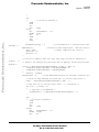
/*****************************************************************************************
*
*
Copyright (C) 2004 Motorola, Inc.
*
All Rights Reserved
*
* Filename:
$RCSfile: LINdriver.c,v $
* Author:
$Author: r57404 $
* Locker:
$Locker: $
* State:
$State: Exp $
* Revision:
$Revision: 1.4 $
*
* Functions:
LIN908QY4 Driver
*
* History:
Use the RCS command log to display revision history
*
information.
*
*
*
*****************************************************************************************/
/*
Includes
#include <MC68HC908QY4.h>
#include "LINdriver.h"
#include "Tx_Config.h"
*/
#pragma DATA_SEG SHORT _DATA_ZEROPAGE
18
Generic LIN Driver for MC68HC908QY4
For More Information On This Product,
Go to: www.freescale.com
Freescale Semiconductor, Inc.
AN2599/D
Appendix — LINdriver.c
Freescale Semiconductor, Inc...
/*
U8
U8
U8
U8
U8
U8
U8
U8
U8
U8
U8
U8
volatile
volatile
volatile
volatile
volatile
volatile
volatile
volatile
volatile
volatile
volatile
volatile
Global Variables*/
near TCH0LBuff, TCH0HBuff, BreakH, BreakL, BreakLimitH, BreakLimitL;
near BitTimeH, BitTimeL, HBitTimeH, HBitTimeL;
near LinState;
near MessageIndex;
near SyncFieldBits;
BitCount, ByteCount;
near SWSCIDR, SWSCIDRB;
near Id ;
near FrameBuffer[9];
near FrameTimeOut, NoRelevantID;
near BitClockReload8H;
near BitClockReload8L;
U8 volatile near checkSleep;
volatile LINERRORSTR _LinERROR;/* Look in the header file to see what this is */
/*
Prototypes
void AddBitTime8(void);
void AddBitTimeH(void);
void AddBitTime(void);
*/
/******************************************************************************************/
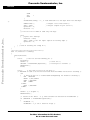
interrupt void TimA1ISR(void)
{
U8 Dummy,i;
if (LinState == ReceiveId)
{
asm
{
/* Shift Rx into Id variable */
ASR Id
BRCLR 1,PTA,LBL8
BSET 7,Id
BRA END1
LBL8:
BCLR 7,Id
END1:
// Finished shifting one
}
.
/* Keep updating the timer to catch the next bit until all 8 are in Id (asm code above)*/
if (BitCount <= 6)
{
AddBitTime();
BitCount++;
}
else
/* got the whole Id */
{
checkSleep = 0;
Generic LIN Driver for MC68HC908QY4
For More Information On This Product,
Go to: www.freescale.com
19
Freescale Semiconductor, Inc.
AN2599/D
Freescale Semiconductor, Inc...
if (Id == SLEEP)
/* sleep defined in LINdriver.h, should be 0x80 */
{
checkSleep = 1;
/* Set flag to make sure checking if first databyte is 0x00 */
LinState = ReceivingWFS;
TSC1 = 0x48;
/* Set for input capture on falling edge */
NoRelevantID = 0;
/* reset NoRelevantId since has received a relevant id */
ByteCount = 0;
}
else
{
LINSleep = 0;
/*stay awake */
BitCount = 0;
/* Reset BitCount and MessageIndex */
MessageIndex = 0xFF;
for (i=0;i < No_of_Ids;i++) /*loop through identifier table... */
{
/* ...to check if Id exist in the table, i.e. is relevant to this node. */
if (Id == IdTbl[i])
{
MessageIndex = i;
/* If found, save away index */
}
}
if (MessageIndex == 0xFF) /* Found no id for this node, keep waiting... */
{
LinState = Idle;
TSC1 = 0x48;
/* Set for input capture on falling edge */
NoRelevantID++; /* Count how many Ids sent out but NOT relevant to this node */
ByteCount = 0;
}
/* Check if master or slave task */
/* Id is relevant for this node and is a "To Receive" Id */
else if ((MessageCountTbl[MessageIndex] & 0xF0) == 0x10)
{
LinState = ReceivingWFS;
TSC1 = 0x48;
/* Set for input capture on falling edge */
NoRelevantID = 0;
/* reset NoRelevantId since has received a relevant id */
ByteCount = 0;
BitCount = 0;
}
else if ((MessageCountTbl[MessageIndex] & 0xF0) == 0)
{/* Id is relevant for this node and is a "To Send" Id */
LinState = Sending;
NoRelevantID = 0;
/* reset NoRelevantId since has received a relevant id */
/* check how many messages the frame has, e.g the Id's byte count */
Dummy = ((MessageCountTbl[MessageIndex] & 0xF) - 1);
/* Loop from i=0 to "the Id's byte count" - 1 (1=checksum) */
for (i=0 ; i <= Dummy;i++)//((MessageCountTbl[MessageIndex] & 0xF) - 1)
{
/* Copy data to framebuffer */
FrameBuffer[i] = *(MessagePointerTbl[MessageIndex] + i);
20
Generic LIN Driver for MC68HC908QY4
For More Information On This Product,
Go to: www.freescale.com
Freescale Semiconductor, Inc.
AN2599/D
Appendix — LINdriver.c
}
Freescale Semiconductor, Inc...
asm
{
/* Calculate checksum */
PSHA
CLRA
CLC
LDX
Dummy
Sloop:
ADC
@FrameBuffer - 1,X
DBNZX
Sloop
ADC
#0
COMA
STA
i
PULA
}
FrameBuffer[Dummy] = i;
/* load Checksum in to the byte after last
databyte */
AddBitTime8();
TSC1 = 0x50;
ByteCount = 0;
BitCount = 0;
}
/* moved on to next sample point - add 8 bit times */
/* Output compare no pin action */
/************ added to make sure only "new" msgs are sent if defined as F
(ignore)
*/
/* Check if the message only should be sent if updated, and the msg has been
updated */
else if (((MessageCountTbl[MessageIndex] & 0xF0) == 0xF0) &&
(LinMsgStatus[MessageIndex]!= LIN_MSG_NOCHANGE) &&
(LinMsgStatus[MessageIndex]!= LIN_MSG_NODATA))
{
LinState = Sending;
NoRelevantID = 0;
/* reset NoRelevantId since has received a relevant id */
/* check how many messages the frame has, e.g the Id's byte count */
Dummy = ((MessageCountTbl[MessageIndex] & 0xF) - 1);
/* Loop from i=0 to "the Id's byte count" - 1 (1=checksum) */
for (i=0; i <= Dummy; i++)
{
/* Copy data to framebuffer */
FrameBuffer[i] = *(MessagePointerTbl[MessageIndex] + i);
}
asm
{
/* Calculate checksum */
PSHA
CLRA
CLC
LDX
Dummy
Sloop2:
ADC
@FrameBuffer - 1,X
DBNZX
Sloop2
ADC
#0
Generic LIN Driver for MC68HC908QY4
For More Information On This Product,
Go to: www.freescale.com
21
Freescale Semiconductor, Inc.
AN2599/D
COMA
STA
PULA
i
}
FrameBuffer[Dummy] = i; /* load Checksum in to the byte after last databyte
*/
AddBitTime8();
TSC1 = 0x50;
ByteCount = 0;
BitCount = 0;
/* Sample 8 bit times ahead */
/* Output compare no pin action */
}
//***************** END of send only new msgs
Freescale Semiconductor, Inc...
else
{ //ignore this message
LinState = Idle;
TSC1 = 0x48;/* Set for input capture on falling edge */
ByteCount = 0;
}
} /* end of checking for sleep ID */
}
}
/***************************************/
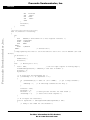
else if (LinState == Sending)
{
switch(BitCount)
{
case 0:
/* Has not started sending yet */
BitCount++;
TxPIN = 0;
/* Start bit */
SWSCIDR = FrameBuffer[ByteCount];
/* Load byte to transmit */
AddBitTime();
break;
case 9:
/* Has sent all bits in the byte */
/* SWSCIDRB is used to store the read value from the LINbus for biterror checking */
asm
{
/* Shift Rx pin in to SoftwareSCIDataRegBackup for BitError checking */
ASR
SWSCIDRB
BRCLR 1,PTA,S9LBL8
BSET 7,SWSCIDRB
BRA
S9END1
S9LBL8:
BCLR 7,SWSCIDRB
S9END1:
}
TxPIN = 1;/* Stopbit */
AddBitTimeH();
/* check for Bit Error - e.g. when someone has messed with FrameBuffer */
if (SWSCIDRB != FrameBuffer[ByteCount])
{
BitERROR = 1;
BitERROR2 = 1;/* Set 2 biterror flags */
22
Generic LIN Driver for MC68HC908QY4
For More Information On This Product,
Go to: www.freescale.com
Freescale Semiconductor, Inc.
AN2599/D
Appendix — LINdriver.c
}
BitCount = 0;
ByteCount++;
Freescale Semiconductor, Inc...
/* Add msg status ---------------*/
/* After data sent from node, its status is changed from
LIN_MSG_UPDATED or LIN_MSG_OVERRUN to LIN_MSG_OK. From
LIN_MSG_OK to LIN_MSG_NOCHANGE.
From LIN_MSG_NODATA or LIN_MSG_NOCHANGE it will stay the same.*/
if (ByteCount >= (MessageCountTbl[MessageIndex] & 0xF))
{
if ((LinMsgStatus[MessageIndex] == LIN_MSG_UPDATED) ||
(LinMsgStatus[MessageIndex] == LIN_MSG_OVERRUN) )
{
LinMsgStatus[MessageIndex] = LIN_MSG_OK;
}
else if ((LinMsgStatus[MessageIndex] & LIN_MSG_OK) != 0 )
{
LinMsgStatus[MessageIndex] = LIN_MSG_NOCHANGE;
}
}
/* end msg status -------------------------*/
/* If all bytes are sent or BitError detected abort transmission */
if ((ByteCount >= (MessageCountTbl[MessageIndex] & 0xF)) || (BitERROR2 == 1))
{
LinState = Idle;/* Back to waiting for Id again... */
BitERROR2 = 0;/* Reset bit error flag */
TSC1 = 0x48;/* Set to IC on falling edge */
}
break;
default:/* In the middle of sending.... */
asm
{
ASR
SWSCIDRB
/* save the active state for Bit ERROR check */
BRCLR 1,PTA,SLBL8
BSET
7,SWSCIDRB
BRA
SEND1
SLBL8:
BCLR
7,SWSCIDRB
SEND1:
/*Shift Rx pin in to SoftSCIDataRegBackup. */
BRCLR 0,SWSCIDR,LBL1
BSET
TxBIT, TxPORT
BRA
END
LBL1:
BCLR
TxBIT, TxPORT
END:
ASR
SWSCIDR
/* AddBitTime */
PSHA
LDA
TCH1L
ADD
BitTimeL
STA
TCH1L
LDA
TCH1H
Generic LIN Driver for MC68HC908QY4
For More Information On This Product,
Go to: www.freescale.com
23
Freescale Semiconductor, Inc.
AN2599/D
ADC
STA
LDA
STA
PULA
BitTimeH
TCH1H
TCH1L
TCH1L
Freescale Semiconductor, Inc...
}
BitCount++;
break;
}
}
/********************************/
else if (LinState == Receiving)
{
asm
{
ASR
SWSCIDR/* Shift RxPin in to Data register variable. */
BRCLR 1,PTA,RLBL8
BSET
7,SWSCIDR
BRA
REND1
RLBL8:
BCLR
7,SWSCIDR
REND1:
/* Shifted one */
}
/* Keep updating the timer to catch the next bit until all 8 are in SWSCIDR (asm code
above)*/
if (BitCount <= 6)
{
AddBitTime();
BitCount++;
}
else
/* Whole byte is in */
{
TSC1 = 0x48;
/* set for input capture on falling edge */
FrameBuffer[ByteCount] = SWSCIDR;/* Save data in buffer */
BitCount = 0;
ByteCount++;
/* if first byte and checkSleep set */
if ((checkSleep == 1) && (ByteCount == 1))
{
if ((FrameBuffer[0] == 0x00) && (Id == SLEEP))
/* got a sleep command */
{
LINSleep = 1;
/* If LIN sleep command set the flag */
}
LinState = Idle;
ByteCount = 0;
BitCount = 0;
checkSleep = 0;
/* Reset process and wait for next break */
/* reset since check complete */
}
/* If all bytes are received */
else if (ByteCount >= (MessageCountTbl[MessageIndex] & 0xF))
{
/* Dummy is the index for the checksum */
24
Generic LIN Driver for MC68HC908QY4
For More Information On This Product,
Go to: www.freescale.com
Freescale Semiconductor, Inc.
AN2599/D
Appendix — LINdriver.c
/* check how many messages (data bytes) the frame has */
Dummy = ((MessageCountTbl[MessageIndex] & 0xF) - 1);
asm
{
Freescale Semiconductor, Inc...
PSHA
CLRA
CLC
LDX
loop:
ADC
DBNZX
ADC
COMA
STA
PULA
Dummy
/* Calculate checksum */
@FrameBuffer - 1,X
loop
#0
i
}
if (i == FrameBuffer[Dummy])
/* If calculated Checksum = received checksum */
{
/* Load data to variables */
for (i=0 ; i < Dummy; i++)
{
*(MessagePointerTbl[MessageIndex] + i) = FrameBuffer[i];
}
}
else
{
ChecksumERROR=1;/* Error - Set ChecksumERROR flag */
}
LinState = Idle;
ByteCount = 0;
BitCount = 0;
/* Reset process and wait for next break */
/*
/*
if
If
If
Added msg status - set appropriate status for received message */
After message received at node, status is changed to LIN_MSG_UPDATED
previously it was in LIN_MSG_NODATA, LIN_MSG_OK or LIN_MSG_NOCHANGE.
it was in LIN_MSG_UPDATED it is changed to LIN_MSG_OVERRUN.
it was in LIN_MSG_OVERRUN it will stay the same.*/
if (( LinMsgStatus[MessageIndex]
( LinMsgStatus[MessageIndex]
( LinMsgStatus[MessageIndex]
{
LinMsgStatus[MessageIndex] =
}
else
{
LinMsgStatus[MessageIndex] =
}
/* end msg status add */
}
== LIN_MSG_OK) ||
== LIN_MSG_NODATA) ||
== LIN_MSG_NOCHANGE))
LIN_MSG_UPDATED;
LIN_MSG_OVERRUN;
/* End if all bytes received */
else /* All bytes are not received yet */
{
Generic LIN Driver for MC68HC908QY4
For More Information On This Product,
Go to: www.freescale.com
25
Freescale Semiconductor, Inc.
AN2599/D
LinState = ReceivingWFS;/* Switch state to catch the next expected start bit
*/
}
}
Freescale Semiconductor, Inc...
}
/*****************************************/
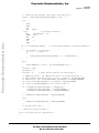
else if (LinState == Idle)
/* case idle = waiting for falling edge break pulse */
{
TCH0HBuff = TCH1H;
/* Save IC value, later used to calculate puls length (in
Possiblesynk)*/
TCH0LBuff = TCH1L;
/* Save IC value, later used to calculate puls length (in
Possiblesynk)*/
TSC1_ELS1A = 1;
TSC1_ELS1B = 0;
/* Set for rising edge int. trig */
LinState = PossibleSynk;
/* Switch state */
SyncFieldBits = 0;
}
/******************************/
else if (LinState == PossibleSynk) /* case PossibleSynk = waiting for rising edge break
pulse */
{
asm
{
PSHA
LDA TCH1L
/* Check current timer */
SUB TCH0LBuff
/* Subtract timer value saved in Idle state */
STA BreakL
/* store difference in BreakL */
BHI lbl3
LDA TCH1H
DECA
BRA lbl33
lbl3:
LDA TCH1H
/* Calculate pulse length between falling and rising edge */
lbl33:
SUB TCH0HBuff
/* Subtract timer value saved in Idle state */
STA BreakH
/* store difference in BreakH */
LDA TCH1L
PULA
}
/* Check if longer than 11 bit times (BreakLimitH = val found in Unsyncronized) */
if (BreakH > BreakLimitH)
{
LinState = Syncbreak;
/* It has found the syncbreak
*/
}
else if ((BreakH == BreakLimitH) && (BreakL >= BreakLimitL))
{
LinState = Syncbreak;
/* If yes - It has found the syncbreak */
}
else
{
LinState = Idle;
/* If No - did not find syncbreak - look again */
}
TSC1_ELS1A = 0;
26
Generic LIN Driver for MC68HC908QY4
For More Information On This Product,
Go to: www.freescale.com
Freescale Semiconductor, Inc.
Freescale Semiconductor, Inc...
AN2599/D
Appendix — LINdriver.c
TSC1_ELS1B = 1;
/* Set for falling edge int. trig */
}
/*****************************/
/* Case Syncbreak = Start at syncfield first falling edge,
count 4 edges and calculate and save Bit time,Bit time x 1.5 and x 8 */
else if (LinState == Syncbreak)
{
if (SyncFieldBits == 0)
{
TCH0HBuff = TCH1H;
/* save away timer values */
TCH0LBuff = TCH1L;
}
else if (SyncFieldBits == 4)
{
/* now calculate how long time has passed */
asm{
PSHA
LDA
TCH1L
SUB
TCH0LBuff
/* subtract saved timer value from new timer value */
STA
BreakL
/* difference (TCH1L-TCH0LBuff) is stored in BreakL */
BHI
lblsb5
/* Branch if Higher */
LDA
TCH1H
DECA
BRA
lblsb55
lblsb5:
LDA
TCH1H
lblsb55:
SUB
TCH0HBuff/* Calculate time between 4 falling edges */
STA
BreakH
MOV
BreakH,BitClockReload8H
MOV
BreakL,BitClockReload8L
/* save 8 x bit time value */
LSR
BreakH
ROR
BreakL
LSR
BreakH
ROR
BreakL
LSR
BreakH
ROR
BreakL
/* BreakL + BreakH >> 3 ie. /8 */
LDA
TCH1L
/* Read needed not to stall TCH1 IC */
MOV
BreakH,BitTimeH
MOV
BreakL,BitTimeL
/* save bit time value */
LSR
BreakH
ROR
BreakL
/* divide by 2 to get 1/2 bit time */
LDA
BitTimeL
ADD
BreakL
STA
HBitTimeL
LDA
BitTimeH
ADC
BreakH
STA
HBitTimeH
/* Calculate 1,5 x Bit time value and save in HBitTimeL/H */
PULA
}
LinState = Syncronised;
}
asm INC SyncFieldBits;
/* Increase SyncFieldBits by 1, when SyncFieldBits =2
or =3. */
}
/**************************/
Generic LIN Driver for MC68HC908QY4
For More Information On This Product,
Go to: www.freescale.com
27
Freescale Semiconductor, Inc.
AN2599/D
Freescale Semiconductor, Inc...
else if (LinState == Syncronised)
{
AddBitTimeH();
/* Add 1,5 bit time */
TSC1 = 0x50;
/* Output compare no pin action */
LinState = ReceiveId;
BitCount = 0;
Id = 0;
}
/**************************/
else if (LinState == ReceivingWFS) /* WFS = WaitForStartbit */
{
AddBitTimeH();
/* Add 1,5 bit time */
TSC1 = 0x50;
/* Output compare no pin action */
LinState = Receiving;
}
/*****************************/
else if (LinState == Unsyncronized)
/* Unsyncronized state = Untrimmed RC Osc. */
{
BitCount++;
/* BitCount var. used to keep falling edge IC count */
if (BitCount >= SyncBitCount)
/* Now it knows how long 2bit times are */
{
BreakLimitH = BreakH;
BreakLimitL = BreakL;
asm{
PSHA
PSHX
LDX
BreakH
LDA
BreakL
ASLA
ROLX
/* multiply by 2 */
ASLA
ROLX
/* multiply by 2 - so X:A has now 2bit times x 4 */
ADD
BreakL
STA
BreakLimitL
/* BreakLimitL has now the LSB of 10 bit times */
TXA
ADC
BreakH
STA
BreakLimitH
/* BreakLimitH has now the MSB of 10 bit times */
LSR
BreakH
ROR
BreakL
/* divide by 2 to get 1 bit time */
LDA
BreakLimitL
ADD
BreakL
STA
BreakLimitL
/* BreakLimitL = 11 bit times LSB */
LDA
BreakLimitH
ADC
BreakH
STA
BreakLimitH
/* BreakLimitH = 11 bit times MSB */
PULX
PULA
}
LinState = Idle;
/* Ready to look for SyncBreak */
}
if (SyncFieldBits == 0)
/* Loop to save away current timer values */
{
TCH0HBuff = TCH1H;
/* Start by saving away timer values */
TCH0LBuff = TCH1L;
28
Generic LIN Driver for MC68HC908QY4
For More Information On This Product,
Go to: www.freescale.com
Freescale Semiconductor, Inc.
Freescale Semiconductor, Inc...
AN2599/D
Appendix — LINdriver.c
SyncFieldBits++;
}
/* Calculate how long time has passed to find out the time between 2 falling edges */
else if (SyncFieldBits == 1)
{
asm{
PSHA
PSHH
PSHX
LDA
TCH1L
/* read timer */
SUB
TCH0LBuff
TAX
BHI
lblus1
LDA
TCH1H
DECA
BRA
lblus2
lblus1:
LDA
TCH1H
lblus2:
SUB
TCH0HBuff
/* Calculate time between 2 falling edges */
PSHA
PULH
CPHX
BreakH
/* Compare to previously captured value */
BCC
endus
/* Branch if value in memory is bigger */
STX
BreakL
PSHH
PULA
STA
BreakH
/* store if lower */
endus:
LDA
TCH1L
/* "release" TCH1L+H */
PULX
PULH
PULA
}
SyncFieldBits = 0;
}
}
Dummy = TSC1;
TSC1_CH1F = 0;
/* Read byte... */
/* ...and reset CH1F in case of a pending interrupt */
}
/************************************************/
/* This function adds 8 bit times*/
void AddBitTime8(void)
{
asm {
PSHA
LDA TCH1L
ADD BitClockReload8L
STA TCH1L
LDA TCH1H
ADC BitClockReload8H
STA TCH1H
LDA TCH1L
Generic LIN Driver for MC68HC908QY4
For More Information On This Product,
Go to: www.freescale.com
29
Freescale Semiconductor, Inc.
AN2599/D
STA TCH1L
PULA
}
Freescale Semiconductor, Inc...
}
/*****************************************/
/* This function adds 1 bit time*/
void AddBitTime(void)
{
asm {
PSHA
LDA TCH1L
ADD BitTimeL
STA TCH1L
LDA TCH1H
ADC BitTimeH
STA TCH1H
LDA TCH1L
STA TCH1L
PULA
}
}
/************************************************/
/* This function adds 1.5 bit times*/
void AddBitTimeH(void)
{
asm {
PSHA
LDA TCH1L
ADD HBitTimeL
STA TCH1L
LDA TCH1H
ADC HBitTimeH
STA TCH1H
LDA TCH1L
STA TCH1L
PULA
}
}
30
Generic LIN Driver for MC68HC908QY4
For More Information On This Product,
Go to: www.freescale.com
Freescale Semiconductor, Inc.
Freescale Semiconductor, Inc...
AN2599/D
Generic LIN Driver for MC68HC908QY4
For More Information On This Product,
Go to: www.freescale.com
31
Freescale Semiconductor, Inc.
How to Reach Us:
Home Page:
www.freescale.com
Freescale Semiconductor, Inc...
E-mail:
[email protected]
USA/Europe or Locations Not Listed:
Freescale Semiconductor
Technical Information Center, CH370
1300 N. Alma School Road
Chandler, Arizona 85224
+1-800-521-6274 or +1-480-768-2130
[email protected]
Europe, Middle East, and Africa:
Freescale Halbleiter Deutschland GmbH
Technical Information Center
Schatzbogen 7
81829 Muenchen, Germany
+44 1296 380 456 (English)
+46 8 52200080 (English)
+49 89 92103 559 (German)
+33 1 69 35 48 48 (French)
[email protected]
Japan:
Freescale Semiconductor Japan Ltd.
Headquarters
ARCO Tower 15F
1-8-1, Shimo-Meguro, Meguro-ku,
Tokyo 153-0064
Japan
0120 191014 or +81 3 5437 9125
[email protected]
Asia/Pacific:
Freescale Semiconductor Hong Kong Ltd.
Technical Information Center
2 Dai King Street
Tai Po Industrial Estate
Tai Po, N.T., Hong Kong
+800 2666 8080
[email protected]
For Literature Requests Only:
Freescale Semiconductor Literature Distribution Center
P.O. Box 5405
Denver, Colorado 80217
1-800-441-2447 or 303-675-2140
Fax: 303-675-2150
[email protected]
Information in this document is provided solely to enable system and software
implementers to use Freescale Semiconductor products. There are no express or
implied copyright licenses granted hereunder to design or fabricate any integrated
circuits or integrated circuits based on the information in this document.
Freescale Semiconductor reserves the right to make changes without further notice to
any products herein. Freescale Semiconductor makes no warranty, representation or
guarantee regarding the suitability of its products for any particular purpose, nor does
Freescale Semiconductor assume any liability arising out of the application or use of
any product or circuit, and specifically disclaims any and all liability, including without
limitation consequential or incidental damages. “Typical” parameters which may be
provided in Freescale Semiconductor data sheets and/or specifications can and do
vary in different applications and actual performance may vary over time. All operating
parameters, including “Typicals” must be validated for each customer application by
customer’s technical experts. Freescale Semiconductor does not convey any license
under its patent rights nor the rights of others. Freescale Semiconductor products are
not designed, intended, or authorized for use as components in systems intended for
surgical implant into the body, or other applications intended to support or sustain life,
or for any other application in which the failure of the Freescale Semiconductor product
could create a situation where personal injury or death may occur. Should Buyer
purchase or use Freescale Semiconductor products for any such unintended or
unauthorized application, Buyer shall indemnify and hold Freescale Semiconductor
and its officers, employees, subsidiaries, affiliates, and distributors harmless against all
claims, costs, damages, and expenses, and reasonable attorney fees arising out of,
directly or indirectly, any claim of personal injury or death associated with such
unintended or unauthorized use, even if such claim alleges that Freescale
Semiconductor was negligent regarding the design or manufacture of the part.
AN2599/D
For More Information On This Product,
Go to: www.freescale.com