1
Technical Description
Order Number: 6AR1943-3AD00-2BA0
IMC0x-PLC, Version 2.0
Order Number: 6AR1403-3AD00-2AA0
System Manual
SICOMP Industrial Microcomputers
(4)J31069-D2037-U001-A3-7618
December 1999
IMC0x-PLC
Product History of the Technical Description
Revision
Record of changes
Date
First edition
07/97
A1
Technical Corrections
06/98
A2
V2.0 with PROFIBUS-DP Connection
05/99
A3
Addition of IMC01 information, designation changed to IMC0x-PLC
12/99
A0
1)
1)
Corresponds to the 4th block of digits of the drawing number in the footer
Notes:
SICOMP® is a registered trademark of Siemens AG.
IBM AT® and IBM PC® are registered trademarks of the International Business Machines Corp.
INTEL® is a registered trademark of the INTEL Corp.
MS-DOS®, Windows® and Windows NT® are registered trademarks of Microsoft.
All other designations used in this documentation may be trademarks whose use by third parties for their own purposes may
violate the rights of the owner.
Passing on and reproduction of this document, as well as utilization and communication of its contents is prohibited unless
expressly authorized. Offenders will be liable for damages. All rights reserved, particularly in the event a patent is granted or a
utility model is registered.
No responsibility is assumed for circuits, descriptions and tables contained in this document concerning freedom from rights of
third parties. Information in the technical descriptions specifies products but does not guarantee characteristics. The product
described in this documentation may require licensing. Questions should be directed to your local Siemens office.
Availability and technical modifications subject to change without prior notice.
2
ES43/Ka/WW8.0/VS5.0/A4
©Siemens AG 1999, All Rights Reserved
(4)J31069-D2037-U001-A3-7618
IMC0x-PLC, System Manual
IMC0x-PLC
Table of Contents
1
2
3
General Information about IMC0x-PLC Documentation
1–1
1.1
1–2
System Manual Overview
IMC0x-PLC Overview
2–1
2.1
Performance Features
2–1
2.2
2.2.1
2.2.2
2.2.3
Before You Start
Programmer (PG)
Controller (PLC)
The Controller
2–1
2–1
2–1
2–2
2.3
2.3.1
2.3.2
2.3.3
2.3.4
2.3.5
2.3.6
2.3.7
2.3.8
2.3.9
2.3.10
Functional Units
Control Unit
Accumulator (ACCUM)
Counters, Timers and Flags
Communication Flags
Process Images
Input/Output Units
Program Memory
MC5 Compiler
PG Interface
Shared Memory
2–3
2–4
2–4
2–4
2–4
2–4
2–4
2–5
2–5
2–5
2–5
Operating Modes
3–1
3.1
Operator Interface and Display Elements
3–2
3.2
Restart
3–2
3.3
Restart (RUN transition)
3–4
3.4
STOP Transition
3–5
3.5
3.5.1
3.5.1.1
3.5.1.2
3.5.1.3
3.5.2
Operating Mode RUN
Cycle-Driven Processing Level
Scan Time Monitoring
Scan Time Calculation
Diagnosis While Reading/Writing the Process Image (Only with IMC05)
Timer-driven Processing Level
3–6
3–6
3–7
3–7
3–8
3–8
3.6
Retentivity
3–11
3.7
3.7.1
3.7.2
3.7.3
Overall Reset
Overall Reset by Event Flag
Overall Reset via the PG
Overall Reset by the System
3–11
3–12
3–12
3–12
3.8
3.8.1
3.8.1.1
3.8.1.2
3.8.1.3
3.8.1.4
3.8.1.5
3.8.1.6
3.8.1.7
Error Handling
Runtime Errors
Scan Time Exceeded
Timer Error
Substitution Error
Transfer Error
Calling Nonexistent Blocks
Block Stack Overflow
STS Operation (STEP 5 Command)
3–12
3–13
3–13
3–14
3–14
3–14
3–14
3–14
3–14
(4)J31069-D2037-U001-A3-7618
IMC0x-PLC, System Manual
3
IMC0x-PLC
3.8.2
3.8.2.1
3.8.2.2
3.8.2.3
3.8.2.4
3.8.2.5
3.8.3
4
5
6
4
IMC0x-PLC -specific Errors
DB 1 Error
Compiling Error
Memory Overflow in Runtime Area
LIR/TIR/TNB Error
Clock Error
Error Status Word
3–15
3–15
3–15
3–16
3–16
3–16
3–17
I/O Addressing
4–1
4.1
Bitwise Addressing
4–1
4.2
Bytewise and Wordwise Addressing
4–2
4.3
Access to the PII
4–2
4.4
Access to the PIQ
4–3
4.5
Direct Access
4–3
4.6
Initializing Outputs
4–5
4.7
Access to Decentral Inputs/Outputs
4–5
Testing and Startup Functions
5–1
5.1
Forcing Variables
5–1
5.2
Forcing Outputs
5–2
5.3
Compressing Memory
5–2
5.4
Direct Signal State Reporting (Status Variables)
5–2
5.5
Program-dependent Signal State Reporting
5–2
5.6
Process Monitoring
5–3
5.7
5.7.1
5.7.2
5.7.3
Output of Interrupt Stack (ISTACK)
Determining the Error Source
ISTACK Output to PG
Mnemonics of ISTACK Entries
5–3
5–3
5–4
5–5
5.8
Block Stack Output
5–6
5.9
System Parameter Output
5–9
5.10
Address Output
5–10
5.11
Display Memory Structure
5–11
5.12
Error Reporting with the Error Status Word
5–11
Introduction to Programming
6–1
6.1
6.1.1
6.1.2
STEP 5 Programming Language
Display Modes
Operand Areas
6–1
6–1
6–3
6.2
6.2.1
6.2.2
Program Structure
Linear Programming
Structured Programming
6–3
6–3
6–4
6.3
6.3.1
6.3.1.1
Blocks and their Attributes
Organization Blocks (OB)
Programming Organization Blocks
6–5
6–6
6–6
(4)J31069-D2037-U001-A3-7618
IMC0x-PLC, System Manual
IMC0x-PLC
7
8
9
6.3.1.2
6.3.2
6.3.2.1
6.3.2.2
6.3.3
6.3.3.1
6.3.3.2
6.3.3.3
6.3.4
6.3.4.1
6.3.4.2
6.3.4.3
6.3.5
Calling Organization Blocks
Program Blocks (PB) and Sequence Blocks (SB)
Programming PBs and SBs
Calling Program and Sequence Blocks
Function Blocks (FB)
Programming Function Blocks
Calling Function Blocks
Parametrization
Data Blocks (DB)
Data Blocks DB 0 and DB 1
Generating Data Blocks
Calling Data Blocks
HLL Blocks
6–6
6–7
6–7
6–7
6–8
6–10
6–12
6–13
6–14
6–14
6–15
6–15
6–17
6.4
Representing Numbers
6–18
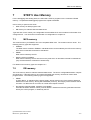
STEP 5 User Memory
7–1
7.1
MC5 memory
7–1
7.2
DB memory
7–1
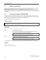
7.3
Memory Organization
7–2
7.4
Conversion Program CVSTEPV.EXE
7–2
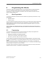
Programming HLL Blocks
8–1
8.1
Block Organization
8–1
8.2
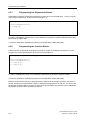
8.2.1
8.2.2
8.2.2.1
8.2.3
8.2.4
Programming
Programming the Organization Blocks
Programming the Function Blocks
Access to Substitution Parameters
Accessing PLC Data Areas
Initialization Function for HLL Blocks
8–1
8–2
8–2
8–3
8–4
8–4
8.3
8.3.1
8.3.2
8.3.3
Linking HLL Blocks
Linking HLL Blocks during RMOS Generation
Stack Size of HLL Blocks
Floating-point Arithmetic
8–5
8–5
8–5
8–5
8.4
8.4.1
8.4.2
8.4.3
Development and Test Environment
Testing at Assembler Level
Testing High Level Languages
Setting Breakpoints
8–6
8–6
8–6
8–6
8.5
HLL Blocks for PROFIBUS-DP Diagnosis (Only with IMC05)
8–7
DB 1 Configuration
9–1
9.1
DB 1 Structure
9–1
9.2
Default Values
9–2
9.3
Definition of Communication Flags (MASK01)
9–3
9.4
9.4.1
9.4.2
Definition of Digital Inputs and Outputs (MASK02 and MASK03)
Definition of Digital Inputs (MASK02)
Definition of Digital Outputs (MASK03)
9–4
9–4
9–7
9.5
Definition of Retentive Flags (MASK04)
(4)J31069-D2037-U001-A3-7618
IMC0x-PLC, System Manual
9–10
5
IMC0x-PLC
10
11
12
13
14
15
6
9.6
Definition of Initialization Values (MASK05)
9–11
9.7
Special Settings (MASK06)
9–12
IMC0x-PLC Configuration
10–1
10.1
IMC0x-PLC Memory Areas
10–1
10.2
10.2.1
10.2.2
Start Call x_plc_start
Structure Definition for Software Parameters
Structure Definitions for Hardware Parameters
10–2
10–2
10–6
10.3
10.3.1
Start Call x_plc_init
Parametrization in the Configuration File SWCPLC.C
10–7
10–8
10.4
Error Codes for x_plc_start and x_plc_init
10–10
10.5
I/O Interface PLC_IOIF.ASM
10–12
10.6
Directory Entries
10–12
Operator Interface and Display Elements
11–1
11.1
What is an Event Flag?
11–1
11.2
Working with Event Flags
11–1
Working with Shared Memory
12–1
12.1
Base Address
12–1
12.2
Structure and Contents
12–1
12.3
12.3.1
12.3.2
Access Control
Access Control Using the Status and Acknowledgement Bytes
Access Control Using the RMOS Event Flag
12–4
12–4
12–4
PROFIBUS-DP Link (Only with IMC05)
13–1
13.1
Access to Decentral Inputs/Outputs
13–1
13.2
13.2.1
13.2.2
13.2.3
PROFIBUS-DP Diagnostic Functions
Diagnostics while Read/Write Accessing the Process Image
Diagnosis While Reading/Writing I/O Bytes
HLL Block for the Diagnostic Function
13–2
13–2
13–3
13–3
13.3
13.3.1
13.3.2
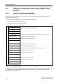
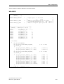
DP Configuration for IMC0x-PLC
Allocation of the Digital Inputs/Outputs (DB 1 Configuration)
Constants for Error Identifiers
13–4
13–4
13–4
RMOS and PLC Configuration
14–1
14.1
Directory Entries
14–2
14.2
IMC0x-PLC Configuration and Generation Files
14–2
14.3
Configuring and Generating IMC0x-PLC
14–3
Compatibility to SIMATIC S5-115U
15–1
15.1
Commands
15–1
15.2
Execution Times
15–1
(4)J31069-D2037-U001-A3-7618
IMC0x-PLC, System Manual
IMC0x-PLC
15.3
Program Memory
15–1
15.4
Data Blocks DB 0/DB 1
15–1
15.5
Special Organization Blocks
15–2
15.6
Display of Results
15–2
15.7
ISTACK Display
15–2
15.8
BASP
15–2
15.9
STATUS Block
15–2
15.10
Alarm Blocks
15–3
15.11
Integrated Function Blocks
15–3
15.12
Standard Function Blocks
15–3
15.13
Clock Functions
15–3
15.14
Time Behavior on Loading Blocks in RUN Mode
15–3
15.15
Step/Transition Programming with GRAPH 5
15–3
15.16
Alarm Blocks
15–3
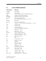
List of Abbreviations
A–1
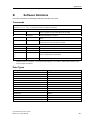
Software Notations
B–1
Index I–1
(4)J31069-D2037-U001-A3-7618
IMC0x-PLC, System Manual
7
IMC0x-PLC
8
(4)J31069-D2037-U001-A3-7618
IMC0x-PLC, System Manual
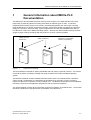
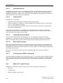
General Information about IMC0x-PLC Documentation
1
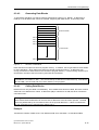
General Information about IMC0x-PLC
Documentation
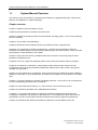
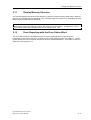
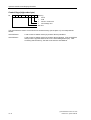
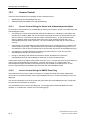
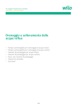
The IMC0x-PLC documentation has been split into three sections in the belief that this is the most
helpful way of presenting all the necessary information for different types of users. It has been
prepared with three user groups in mind: firstly, the absolute beginners who want to get a working
grasp of IMC0x-PLC as quickly as possible, secondly, users writing STEP 5 programs who will use it
mainly as a reference work and, lastly, system programmers who also need detailed information on
how IMC0x-PLC fits into the RMOS operating system. We hope this documentation will help all three
groups to begin working confidently with this product in as short a time as possible.
Getting to know
IMC0x-PLC
User
M an
ua
Figure 1. 1
STEP 5 reference
l
Refe
re
M an n ce
ual
IMC0x-PLC configuration,
STEP 5 programming
Syst
e
M an m
ual
Target uses for manuals
The User Manual is intended for getting acquainted with and gaining a general overview. The manual
covers all the basics of installing, starting and using the IMC0x-PLC under the RMOS operating
system.
The Reference Manual contains detailed information about STEP 5 commands, STEP 5 operation
codes, the DB 1 configuration, the parameters of the IMC0x-PLC start calls, in short, everything
required for IMC0x-PLC operation, mostly in tabular form. The Reference Manual is thus the standard
reference work for both the application programmer and the system programmer.
The System Manual contains all the information required for operation of the IMC0x-PLC. The manual
describes in detail all the special features and facilities of the IMC0x-PLC.
(4)J31069-D2037-U001-A3-7618
IMC0x-PLC, System Manual
1–1
General Information about IMC0x-PLC Documentation
1.1
System Manual Overview
This manual covers the operation, programming and startup of a programmable logic control (PLC)
based on the RMOS3-PLC software package.
Chapter overview
Chapter 1 explains the documentation concept.
Chapter 2 briefly describes a controller's functional units.
Chapter 3 explains the operating modes and the methods of changing them. It also covers retentivity
and error handling.
Chapter 4 covers STEP 5 I/O addressing.
Chapter 5 describes test and startup functions using SIMATIC STEP 5 programmers.
Chapter 6 is an introduction to STEP 5 programming. It outlines the three display modes and
discusses the modular program structure and the different types of module or block. STEP 5 number
representation is also explained in some detail.
Chapter 7 looks at the user memory available under STEP 5 and at a conversion program which
generates an MC5 binary file.
Chapter 8 covers HLL (high level language) blocks and how they are linked to STEP 5 programs.
Chapter 9 concentrates on data block 1 (abbreviated to DB 1) which always contains the PLC
configuration data. It discusses the different data fields (masks) which make up DB 1 and gives an
example of a typical DB 1.
Chapter 10 covers IMC0x-PLC configuration, memory areas used from IMC0x-PLC and the different
IMC0x-PLC start calls. It also deals with the I/O interfaces and explains how the IMC0x-PLC handles
them.
Chapter 11 covers the IMC0x-PLC operator and display elements. The function of an event flag and
its use in manipulating the IMC0x-PLC is explained.
Chapter 12 is about the shared memory. It covers structure, uses and memory access.
Chapter 13 summarizes all details of the PROFIBUS-DP interface.
In chapter 14 you will find a discussion of aspects of the RMOS configuration which affect the
configuration, installation and operation of the IMC0x-PLC. An important part deals with the driver
responsible for serial communication between the IMC0x-PLC and the programming equipment.
Chapter 15 summarizes the differences between the IMC0x-PLC and a SIMATIC S5-115U.
1–2
(4)J31069-D2037-U001-A3-7618
IMC0x-PLC, System Manual
IMC0x-PLC Overview
2
IMC0x-PLC Overview
You can use the IMC0x-PLC to set up a programmable controller with the SICOMP-IMC05 and the
SICOMP-IMC01. This manual concentrates on the programming language STEP 5, on IMC0x-PLC
operation and on test and startup functions using the programmer. In addition, the manual describes
IMC0x-PLC configuration in an RMOS environment and describes the interfaces to another RMOS
task or to another CPU.
2.1
Performance Features
•
1024 input bits
•
1024 output bits
•
256 flag bytes
•
128 timers
•
128 counters
•
3.2 msec execution time for 1024 binary instructions
•
STEP 5 command set corresponds largely to SIMATIC S5-115U CPU 944
2.2
Before You Start
2.2.1
Programmer (PG)
You can write, test and run your application programs on either of these programming systems:
•
MS-DOS-compatible PC with Siemens STEP 5 programming package (STEP 5 Basic Package)
•
SIMATIC S5 programmer, e.g., PG 720 with STEP 5 from V6.5 or PG 740 with STEP 5 from
V7.12 under Windows 95
2.2.2
Controller (PLC)
You can use the IMC0x-PLC to implement programmable controllers based on the IMC05 or IMC01
compact process computer.
(4)J31069-D2037-U001-A3-7618
IMC0x-PLC, System Manual
2–1
IMC0x-PLC Overview
2.2.3
The Controller
A controller created using the IMC0x-PLC has almost all the functionality of a SIMATIC S5-115U
controller. Because the IMC0x-PLC can be implemented on devices with different order options, it is
obviously impossible to describe the final controller completely. The checklist below tells you where
the controller description must be supplemented or modified:
•
Serial interface for connection of the PG
– With IMC05: RS 232-2
– With IMC01: COM1 (RS 232)
•
Number and addresses of inputs and outputs
•
Memory configuration
•
Retentivity
•
Use of communication flags
•
Integrated HLL blocks
•
Reaction to power failure
•
Second serial interface
– With IMC05: RS 232-1
– With IMC01: COM2 for printf outputs on the system console (RS 485, semi-duplex)
2–2
(4)J31069-D2037-U001-A3-7618
IMC0x-PLC, System Manual
IMC0x-PLC Overview
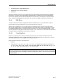
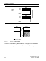
2.3
Functional Units
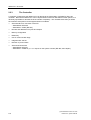
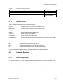
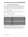
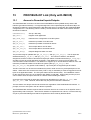
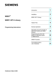
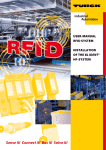
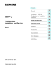
The figure below shows the typical structure of a controller created with the IMC0x-PLC.
RMOS3
PLC
IMC0x-PLC
other Tasks,
e.g.:
ACCUM
Visualization
Operation
Measurement
Control
User memory
Communication
flags
Cycle control
Timers
Counters
Flags
PG communication
(e.g. STATUS block)
PG interface
MC5 compiler
PII
PIQ
logical address
DB 1
physical address
Digital
input/output
Figure 2. 1
Function units of a PLC
The controller is built up from a number of functional units which are briefly described here:
•
Control unit
•
Accumulator
•
Counters, timers and flags
•
Communication flags and shared memory
•
Process image
•
I/O units
•
Program memory
•
MC5 compiler
•
PG interface
(4)J31069-D2037-U001-A3-7618
IMC0x-PLC, System Manual
2–3
IMC0x-PLC Overview
2.3.1
Control Unit
The control unit is responsible for executing control programs at a level where process control is:
•
cycle-driven processing level
•
timer-driven processing level
2.3.2
Accumulator (ACCUM)
The accumulator is an arithmetic register. Values from internal counters and timers, for example, are
loaded via the accumulator. The accumulator also performs compare, convert and arithmetic
operations.
2.3.3
Counters, Timers and Flags
The controller makes available internal counters, timers and flags. Flags are memories for storing
signal states and intermediate results. Counters, timers and flags can be set to be retentive, so that
their contents are not lost when power is switched off (see chapter 3.6).
2.3.4
Communication Flags
A contiguous flag area can be defined an output communication flag or an input communication flag.
If another RMOS task or the CPU is in communication with the controller, these communication flags
are available to them for both reading and writing.
This allows data to exchanged between the PLC and its communication partners, or specific
operations of the control program to be synchronized with operations in other tasks.
2.3.5
Process Images
The controller stores the signal states of its inputs and outputs in process images. Process input
images are treated differently from process output images:
•
Process input images (PII):
are read only at the beginning of a PLC cycle. During the cycle, the PII data is only accessed to
check that the signal states have remained unchanged while the control program was executing.
•
Process output images (PIQ):
are written to only at the end of a PLC cycle. There is no output during the cycle to avoid
changing the outputs unnecessarily with intermediate results from the control program.
2.3.6
Input/Output Units
Logical input units (input bytes) are read and logical output units (output bytes) are read from and
written to peripheral devices. Logical inputs/outputs are allocated to physical inputs/outputs during
DB 1 configuration.
2–4
(4)J31069-D2037-U001-A3-7618
IMC0x-PLC, System Manual
IMC0x-PLC Overview
2.3.7
Program Memory
There are different memory types which can be used to store control programs or to transfer program
data from the PG to the controller:
•
battery-buffered SRAM
•
User flash memory (subsequently abbreviated as EPROM)
2.3.8
MC5 Compiler
The processor in the controller cannot process MC5 code unless it is compiled, i.e., translated into the
appropriate 80386 code. The MC5 code is compiled into 80386 code at every restart of the PLC (after
power-on or start of the IMC0x-PLC under RMOS), or when a program block is loaded from the PG.
2.3.9
PG Interface
The controller is connected to the PG via a serial interface. The PG is used to load, test and start
control programs and in error diagnosis.
2.3.10
Shared Memory
When the controller communicates with another RMOS task it uses shared memory. The following
data is exchanged via shared memory:
•
controller operating mode
•
process image PA, i.e., controller input (PII) and output state (PIQ)
•
counters and timers
•
communication flags to synchronize the controller with other tasks under RMOS
See chapter 12 for details of shared memory structure, configuration and programming.
(4)J31069-D2037-U001-A3-7618
IMC0x-PLC, System Manual
2–5
IMC0x-PLC Overview
2–6
(4)J31069-D2037-U001-A3-7618
IMC0x-PLC, System Manual
Operating Modes
3
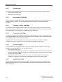
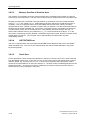
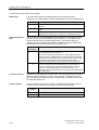
Operating Modes
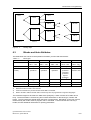
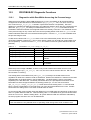
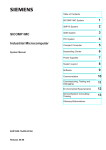
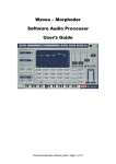
The PLC has two operating modes, RUN and STOP.
•
In RUN mode, the process input image is read cyclically, the user program is executed and the
process output image is written.
•
In STOP mode, control is stopped and all outputs set to zero.
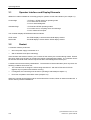
The transition from STOP to RUN is a restart. After power-on, a restart is executed, so that the
necessary initialization functions are performed.
Power-On/Reset
Restart
PLC function PC STOP
RUN-STOP event flag
Compiler error
PROFIBUS-DP error
PG function PC START
RUN-STOP event flag
STOP mode
RUN transition
RUN mode
STOP transition
PG function PC STOP
RUN-STOP event flag
Runtime error
PROFIBUS-DP error
Figure 3. 1
PLC modes and operating mode transition
(4)J31069-D2037-U001-A3-7618
IMC0x-PLC, System Manual
3–1
Operating Modes
3.1
Operator Interface and Display Elements
IMC0x-PLC makes available an event flag group for operator control and indication (see chapter 11).
Control flags
- For RUN ↔ STOP change in operating mode
- For overall reset of the PLC
- For error acknowledgment
Indication flags
- For RUN and STOP operating modes
- For runtime errors, compiling errors and warnings
- For an overall reset request
The controller displays STOP/RUN modes as follows:
STOP mode
The STOP display is active and the RUN display inactive
RUN mode
The RUN display is active and the STOP display inactive
3.2
Restart
A controller restart is performed:
•
when the power supply is switched on or
•
after a hardware reset (from watchdog)
If the controller has retentive memory, the contents of this memory are checked during restart. Should
this check show a loss of data, an overall reset request is automatically initiated. The controller cannot
be switched into RUN mode until this request has been acknowledged and acted upon.
A restart executes all necessary initializations. The transition to RUN mode takes place only when the
following conditions have been met:
•
The controller was not stopped - before being switched off - with the PG function PC STOP
(applies only to systems with retentive memory)
•
If configured, the control flag must be set for operating mode RUN(see chapter 11)
•
Error-free compilation of the MC5 codes (compiler run)
When the controller enters RUN mode for the first time after a restart, OB 22 is called as restart OB. It
can be used to perform initializations.
3–2
(4)J31069-D2037-U001-A3-7618
IMC0x-PLC, System Manual
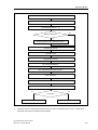
Operating Modes
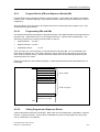
Restart
Delete shared memory
Load retentive data (F, T, C)
1)
yes
Retentive data OK?
no
Request general reset, delete DB memory
Compile DB memory
Load MC5 code
1)
Compile MC5 memory
DB 1 default initialization
DB 1 initialization with data from DB 1
Load HLL blocks
1)
Compile MC5 code, compiler run
Delete non-retentive data (PII, PIQ, F, T, C)
no
yes
PLC RUN ?
STOP mode
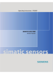
Figure 3. 2
1)
Start (RUN transition)
Restart operation
If retentive mode is configured and retentive data are valid in the SRAM, these are used. Otherwise the
applicable data areas are loaded from the EPROM.
(4)J31069-D2037-U001-A3-7618
IMC0x-PLC, System Manual
3–3
Operating Modes
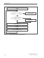
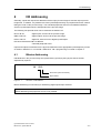
3.3
Restart (RUN transition)
The restart is executed every time the operating mode changes from STOP to RUN.
Start
Read communication flags (if available)
Disable cycle time monitoring
Enable timer processing
Execute start OB (OB 21/OB 22)
Enable alarms
Enable cycle time monitoring
End
Figure 3. 3
Restart
The restart (RUN transition) is initiated by one of the following events:
•
Executing the PG function PC START
•
After a restart, if all RUN conditions have been met
•
In response to an event flag (see chapter 11)
When the controller enters RUN mode for the first time after a restart, the restart OB 22 is executed.
At each subsequent operating mode change from STOP to RUN, restart OB 21 is executed.
If the most recent controller STOP was initiated by the PG function PC STOP, then it can also be
started again by using the event flag group, independently of the PG function PC START.
3.4
STOP Transition
A transition from RUN to STOP interrupts processing of the control program at the end of a PLC cycle,
all outputs are set to zero. For application-specific requirements, STOP OB (OB 28) should be the last
function to be called.
3–4
(4)J31069-D2037-U001-A3-7618
IMC0x-PLC, System Manual
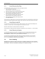
Operating Modes
The PROFIBUS-DP communication remains, but in state "CLEAR".
Note:
All local and decentral outputs assume the value 0.
STOP transition
Disable alarms
Disable timer processing
Copy retentive data to retentivity memory
Delete and write process image and peripheral area
Delete non-retentive data (flags, timers, counters)
Call STOP OB (OB 28) or error OB
End
Figure 3. 4
STOP transition
The transition to STOP takes place after one of the following events:
•
Execution of the PG function PC STOP
•
Occurrence of a runtime error which is not caught by an error OB
•
Resetting an RMOS event flag (see chapter 11)
•
Occurrence of an error at a PROFIBUS-DP station for which "QVZ = J" is specified.
(4)J31069-D2037-U001-A3-7618
IMC0x-PLC, System Manual
3–5
Operating Modes
3.5
Operating Mode RUN
RUN is the operating mode in which control programs are executed. Control programs are executed
at two processing levels:
•
Cycle-driven processing level (PLC cycle)
•
timer-driven processing level
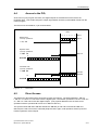
3.5.1
Cycle-Driven Processing Level
This is the typical processing method for programmable controllers, i.e., read input - process control
program - write to output. The organization block OB 1 is the interface for cyclic processing of a
control program.
PLC cycle
Read PII
Call organization block OB 1
Write PIQ
1)
Copy PII to the shared memory
Copy PIQ, timers, counters, communication output flags
to the shared memory
Read communication input flags from the s hared memory
STOP condition?
no
yes
STOP transition
Figure 3. 5
1)
PLC cycle, cycle-driven processing
See chapter 12
The accessibility of all decentral stations configured in the CP data base is monitored during both read
and write accesses to the process image during the PLC cycle.
3–6
(4)J31069-D2037-U001-A3-7618
IMC0x-PLC, System Manual
Operating Modes
3.5.1.1
Scan Time Monitoring
Scan time is another way of saying "the runtime of the control program". It is directly dependent on the
reaction time of the automation system at the cycle-driven processing level.
Scan time monitoring makes it possible to react to unexpected delays in program execution and to
bring the control system into a defined mode. The maximum scan time is usually set in the restart
organization blocks (OB 21 and/or OB 22) by writing a value to system data word SD 96 (see
chapter 5). The value entered here is interpreted as a multiple of 10 msec. The default value for scan
time monitoring is 500 msec. Cycle time monitoring can be switched off by entering a value zero in
system data word 96.
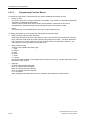
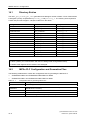
Table 3. 1
Programming scan time monitoring
System data
word
Absolute
address
Time interval Programming
Default Setting
SD 96
EAC0
1 ... 0FFFFH * 10 msec
(0 = no scan time monitoring)
0032H
(500 msec)
Within a program, scan time can be retriggered by calling trigger OB 31. This makes it possible to
adjust scan time monitoring to changing runtime situations.
If the set scan time is exceeded, error OB 26 is executed (if it is available) and the scan time
retriggered. If OB 26 was not programmed, the controller switches to STOP mode.
A special case occurs when scan time monitoring is switched off and the user program is in an
endless loop, so that it does not stop. If the operating mode flag is set to STOP, the controller will still
be in RUN mode. In this case, the overall reset flag must be set in order to terminate the PLC cycle,
because all the other conditions which would cause a STOP are only polled at the end of a cycle.
When the reset button is used here, the controller displays the error message "scan time exceeded"
and switches to STOP mode.
3.5.1.2
Scan Time Calculation
The controller provides data on user program runtime in a time base of 1 to 10 msec (resolution
depends on the RMOS clock tick).
The values for current, minimum and maximum scan time are written to system data as listed below.
They can be read with the PG function "output addresses".
System data
word
Absolute
address
Contents/meaning
SD 121
EAF2
Current scan time in msec
SD 122
EAF4
Maximum scan time in msec
SD 123
EAF6
Minimum scan time in msec
Current scan time is also written to the shared memory (see chapter 12). Scan time calculation, which
takes up a certain amount of the processor's time, must be activated by an entry in DB 1 (see
chapter 9). When SD 122 or SD 123 are set to the value 0, a new measurement is started.
(4)J31069-D2037-U001-A3-7618
IMC0x-PLC, System Manual
3–7
Operating Modes
3.5.1.3
Diagnosis While Reading/Writing the Process Image (Only with
IMC05)
During the PLC cycle, accessibility of all decentral stations configured in the DP data base is
monitored. If errors occur, error information is stored in system data words SD 124 to SD 126. See
chapter 3.8.3. These system data words are cleared during the STOP → RUN transition.
Note:
When an error occurs on a station for which "QVZ = J" is specified in the PROFIBUS-DP data base,
IMC0x-PLC assumes STOP status. When "QVZ = N" is specified for one or more stations, the error
code must be evaluated in system data word SD 124 and then cleared.
The error code can contain all the error identifiers of the PROFIBUS-DP link. For the meaning of the
error codes, see the technical description of IMC05-DP.
3.5.2
Timer-driven Processing Level
At the timer-driven processing level a program (block) can be processed cyclically within a time frame
of 10 msec to 10 min, which you specify.
Timer-driven processing uses the organization blocks OB 10 to OB 13 (timer blocks). The time
interval for each of the 4 organization blocks is set by an entry in the system data. The time frame can
be set in steps of 10 msec. Time intervals can be set by commands in the restart organization blocks
and also adjusted during program runtime by programming the system data words SD 100 to SD 97.
Default time interval settings are: OB 13 100 msec and OB 10, OB 11 and OB 12 all set to zero. If a
time interval is set to zero, calls to the corresponding OB are disabled.
If a timer block is activated during runtime by a programmed time interval, the first start of this timer
block will have a fuzziness of 10 msec.
The following table shows how timer OBs are allocated to system data words:
Table 3. 2
Timer block settings
System data
word
Absolute
address
Time interval Programming
Default Setting
SD 100
EAC8
OB 10: 0 ... 0FFFFH * 10 msec
(0 = disable OB 10 calls)
0 (disabled)
SD 99
EAC6
OB 11: 0 ... 0FFFFH * 10 msec
(0 = disable OB 11 calls)
0 (disabled)
SD 98
EAC4
OB 12: 0 ... 0FFFFH * 10 msec
(0 = disable OB 12 calls)
0 (disabled)
SD 97
EAC2
OB 13: 0 ... 0FFFFH * 10 msec
(0 = disable OB 13 calls)
000AH
(100 msec)
In the following example, the time interval for OB 13 is programmed in the restart OBs 21 and 22.
Access to the system data word is only possible via function blocks (FB 21).
3–8
(4)J31069-D2037-U001-A3-7618
IMC0x-PLC, System Manual
Operating Modes
Table 3. 3
Setting of a time interval (1 sec period for OB 13 calls)
OB 21
Name
OB 22
JU
FB 21
: Time ON
.
.
Name
FB 21
: JU
FB 21
: Time ON
.
.
Name
:
:
:
:
Time ON
L
KF 100
T
RS 97
BE
A cyclic program can be interrupted by a timer-driven processing level. The IA command disables
calls to all timer OBs, and the RA command enables them again.
If the processing time for a timer OB is longer than the set time interval (i.e., the timer OB overtakes
itself), then an timer error occurs (see chapter 3.8.1.2). A timer error also occurs when tasks with
higher priority than the timer blocks take up too much processor time, impeding execution of the timer
blocks. If the time OBs are delayed by the IA command, no time interrupt error occurs. To keep
impact on the cyclic program execution as low as possible, execution time for timer-driven processing
level should be kept small.
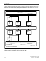
The flowchart below shows all these relationships:
(4)J31069-D2037-U001-A3-7618
IMC0x-PLC, System Manual
3–9
Operating Modes
START
Previous call completed?
no
Timer error handling
yes
Timer OB processing
disabled by "IA"?
yes
no
Wait for "RA"
Restart time interval
Call timer OB
Wait for time interval to elapse
Figure 3. 6
3–10
Calling a program at the timer-driven processing level
(4)J31069-D2037-U001-A3-7618
IMC0x-PLC, System Manual
Operating Modes
3.6
Retentivity
Retentive data like flags, counters, timers and data blocks are stored in DB memory. The size of this
memory is set during configuration (see chapter 10). For DB memory SRAM must be configured.
Otherwise retentive data storage is not possible.
Since data blocks are generally stored in retentive memory, they are always retentive. Flags, timers
and counters are saved to retentive memory only on a transition to STOP mode, or if there is a power
failure.
Note:
The retentivity of the data blocks depends only on the type of memory configured. On the other
hand, the retentivity of the operand areas - flags, timers and counters - must also be specially set in
the DB 1 configuration. During restart the contents of retentive memory are checked. If there has
been a data loss, an overall reset request is automatically issued.
An entry in the DB 1 configuration (see chapter 9) can define a flag area (FB 0 to FB 127) as retentive
data. These data are retained even when program execution is interrupted and are available when
the operating mode has changed back to RUN. If retentive flags have been configured, the operand
areas C 0 to C 63, T 0 to T 63 are automatically made retentive too.
Note:
An overall reset deletes even retentive data.
3.7
Overall Reset
The "overall reset" function re-initializes the controller. All blocks previously loaded by the PG into
RAM are lost, together with the retentive data blocks. After the overall reset, the MC5 code is loaded
from EPROM again.
An overall reset can be requested in the following ways:
•
Via the PG
•
Automatically after data loss in retentive memory (after a restart)
•
In response to an event flag (see chapter 11)
•
Via a new start after a hardware reset.
The reset request is indicated by setting the overall reset flag.
(4)J31069-D2037-U001-A3-7618
IMC0x-PLC, System Manual
3–11
Operating Modes
3.7.1
Overall Reset by Event Flag
The following steps assume that the operating mode flag is at STOP.
1.
Set control flag for overall reset.
Indication flag for overall reset request is set.
2.
Wait until indication flag for overall reset request is reset.
3.
Set control flag for operating mode change to RUN.
Indication flag for RUN operating mode is set.
4.
Set control flag for operating mode change to STOP.
Indication flag for STOP operating mode is set.
5.
Set control flag for operating mode change to RUN.
PLC begins operation.
If the controller is in RUN mode, an overall reset request made by the control flag does not take effect
until the control flag for operating mode change is set to STOP or the PC STOP function is executed.
3.7.2
Overall Reset via the PG
An overall reset is requested with the function "Delete all blocks" and is executed immediately if the
controller is in STOP mode. No acknowledgement is expected in this case.
After the overall reset the controller remains in STOP mode.
If the controller is in RUN mode the PG request is not passed on to the controller, i.e., it has no effect.
3.7.3
Overall Reset by the System
An overall reset request from the system can happen only with controllers where DB memory has
been configured as retentive memory. An overall reset request must always have a positive
acknowledgement. Only then can controller operation be continued.
An overall reset is requested by the system when the controller is switched on for the first time,
because the required memory areas are not yet initialized. When the size of the MC5 memory
(mc5_size) is changed, an overall reset is also requested.
3.8
Error Handling
Basically there is a difference between runtime errors (compatible to SIMATIC S5-115U, see below)
and IMC0x-PLC-specific error code which is written to a reserved system datum, the error status word
(see chapter 5). All errors are indicated by activating the error display (event flag).
3–12
(4)J31069-D2037-U001-A3-7618
IMC0x-PLC, System Manual
Operating Modes
3.8.1
Runtime Errors
Runtime errors can occur only while a user program is executing, i.e., in RUN mode, because their
source is the STEP 5 program code. Runtime errors are usually read out at the PG by displaying the
ISTACK.
The following runtime errors can occur when the IMC0x-PLC is running:
•
scan time exceeded
•
timer error
•
substitution error
•
transfer error
•
call of nonexistent block
•
block stack overflow
•
STS command
Note:
The "SAC" indication always has the value 0 for errors TRF, SUF, STUEB and QVZ (i.e., SAC cannot
be used for error localization here). The incorrect code location can be determined by BEF-REG.
Errors are indicated by setting the error flag. Digital outputs are deleted, processing of the controller
program stops (exception: see chapter 3.8.1.5) and the controller goes into STOP mode.
Before processing can start again, the error must be acknowledged.
Acknowledgement by event flag:
Acknowledgement by event flag is application-specific and must be programmed as part of the
controller realized with the IMC0x-PLC.
With the exception of block stack overflow, timer error and the special case of an STS command, an
error reaction can be programmed for all runtime errors (error OB).
If no STS command (immediate stop) has been programmed in the error OB, the error OB is
processed and then controller program processing is continued without any error display. In effect this
suppresses error display.
If the appropriate error OB is not available, the controller switches into STOP mode as described
above. During transition to STOP mode after a runtime error, the STOP OB (OB 28) is not called.
3.8.1.1
Scan Time Exceeded
Scan time is exceeded when the scan time entered in the system data word SD 96 is exceeded, i.e.,
when the PLC program does not reach the end of a cycle within this time. The scan time monitoring
can be deactivated by entering the value 0 in the system data word SD 96.
3.8.1.2
Timer Error
A timer error occurs when a timer OB overtakes itself, i.e., when it is due to be started again although
the previous processing has not yet finished. When a timer error occurs, the controller goes into
STOP mode. An error OB cannot be programmed for timer errors.
(4)J31069-D2037-U001-A3-7618
IMC0x-PLC, System Manual
3–13
Operating Modes
3.8.1.3
Substitution Error
A substitution error occurs when, in a substitution instruction, the formal operand does not match the
specified actual operand. In the case of a substitution error, the error OB 27 is executed and the
substituted command is omitted. If error OB 27 was not programmed, the controller goes into STOP
mode and the error code is written to the ISTACK.
3.8.1.4
Transfer Error
A transfer error occurs when
•
data words are accessed, but no data block was previously called
•
during a read/write on a data block, a data word/data byte is addressed which is not part of the
block, i.e., block length is exceeded
•
an I DB command is being executed, but the free user memory is insufficient to create a data
block of the specified length.
In the event of a transfer error, the operation which was the source of the error is not executed,
instead error OB 32 is called. If error OB 32 was not programmed, the controller goes into STOP
mode and error code is written to the ISTACK.
3.8.1.5
Calling Nonexistent Blocks
This error occurs when a block call command (JU xx, JC xx) specifies a block which was not
programmed. In this case error OB 19 is called (if it was programmed) instead of the nonexistent
block. The controller does not go into STOP mode, but the error flag is set to indicate an error.
3.8.1.6
Block Stack Overflow
Block nesting depth is restricted to 32. A block stack overflow occurs when the nesting depth of 32
block calls is exceeded (i.e., when the 33rd block is called). When this happens, the controller goes
immediately into STOP mode and the ISTACK error code is entered. It is not possible to program any
other reaction for this error.
The order in which block calls were issued can be displayed with the PG function "OUTPUT
BSTACK".
3.8.1.7
STS Operation (STEP 5 Command)
The STS operation (immediate stop) is actually not an error. In contrast to the STP operation (stop at
end of cycle), the STS operation is generally used in OBs in order to stop the PLC in a defined state.
The STS operation causes an entry to be made in the ISTACK and the controller to go into STOP
mode.
3.8.2
IMC0x-PLC -specific Errors
In addition to runtime errors, there are other errors which are specific to the IMC0x-PLC:
•
DB 1 error
•
Compiling error
•
Memory overflow in runtime area
3–14
(4)J31069-D2037-U001-A3-7618
IMC0x-PLC, System Manual
Operating Modes
•
LIR/TIR/TNB error (illegal address area)
•
Read/write error in retentive data file
•
Clock error
When one of these errors occurs, the IMC0x-PLC goes into STOP mode and sets the error display
(event flag). In general, unless specifically stated otherwise, the IMC0x-PLC can be started again
from the PG, although the error should naturally be corrected first. (The sequence "request overall
reset - negative acknowledgement" will switch the controller into RUN mode without using the PG.
3.8.2.1
DB 1 Error
The DB 1 data block contains configuration data for the IMC0x-PLC, e.g., the allocation of logical
inputs/outputs to physical addresses in the inputs/outputs (see chapter 9).
When a DB 1 containing an error is loaded, then the appropriate error bit in the error status word
SD 104 (see chapter 3.8.3) is set and the IMC0x-PLC goes into STOP mode, or alternatively cannot
be switched into RUN mode. Corrective action in this case is to correct and reload the DB 1. Then
start the IMC0x-PLC using the PG function PC START. The causes of an incorrect DB1 are described
in chapter 5 (DB 1 configuration) of the reference manual.
3.8.2.2
Compiling Error
Each time a new start of the PLC is performed and each time the blocks are loaded via the PG,
compiling is performed again. If illegal commands or command sequences are found, bit 15 of error
status word SD 104 is set. The illegal code in stored in SD 111.
Illegal command sequences are listed below.
•
0 after 0
•
Jump with JO =, JZ =, JM =, JU =, JN =, JP = or JC = in a logical chain with the commands A =,
O =, AN =, ON =, AW =, OW =, XOW =, UM, OM, UNM, ONM, UZ, OZ, UNZ, ONZ, A(, O(, ), UE,
UA, OE, OA, UNE, UNA, ONE, ONA, UT, OT, O, UNT, ONT.
Note:
The PLC cannot be put into RUN status again by deleting the incorrect block. The PLC can only be
put into RUN status again by deleting the invalid command in the block or after a new error-free block
has been loaded.
(4)J31069-D2037-U001-A3-7618
IMC0x-PLC, System Manual
3–15
Operating Modes
3.8.2.3
Memory Overflow in Runtime Area
The compiler run generates processor code from MC5 code. The 80386 code is written to a special
memory area, the runtime area. The size of the runtime area is a multiple of the size of the MC5 code.
Normally, program size is restricted in the first instance by the amount of memory needed for MC5
code (mc5_size, see chapter 10), i.e., while loading a block the PG reports "Insufficient memory in
controller". Only in exceptional cases, where the 80386 code requires more memory area than
expected will the error "Memory overflow in runtime area" be reported. This also means that memory
for MC5 code is almost completely full. The function "Compress memory" will release unnecessarily
occupied memory area, also in the runtime area. If the problem cannot be solved in this way, i.e.,
there is still insufficient memory, the parameter mc5_size must somehow be set larger. If, on the
other hand, compressing memory released a sufficiently large memory area, then the controller can be
started again from the PG. The controller can be switched back into RUN mode only after
compressing memory.
3.8.2.4
LIR/TIR/TNB Error
This error is reported when the commands LIR/TIR/TNB access addresses which are not available
under the IMC0x-PLC. This error is also reported when the TNB command attempts to copy data
beyond range limits.
3.8.2.5
Clock Error
For the different PLC timer functions the IMC0x-PLC requires a 10 msec clock cycle, which is derived
from the RMOS system clock. At the end of every 10 msec timer interval, the internal timer routine is
called to update, e.g., the times T 0 to T 127. A clock error is reported if this internal timer routine
cannot be processed within a 10 msec time interval, i.e., the timer routine is started again before it has
finished processing. The clock error report is initiated by an internal monitoring function when the
system load (e.g., from interrupts) is too heavy.
3–16
(4)J31069-D2037-U001-A3-7618
IMC0x-PLC, System Manual
Operating Modes
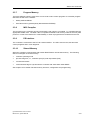
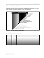
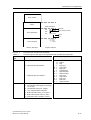
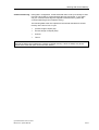
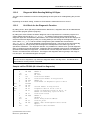
3.8.3
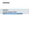
Error Status Word
The error status word SD 104 (address EAD0) is used to report IMC0x-PLC-specific errors.
Information on the cause of the error is entered in the system data words SD 105 to SD 111. These
system data words can be read out with the PG function "Output addresses".
15 14 13 12 11 10 9
8
7
6
5
4
3
2
1
0
PB not available
SB not available
FB not available
OB not available
DB 1 error
Timer error
Clock error
Error on writing retentivity file
LIR/TIR/TNB error (illegal address area)
Access outside DB (TRAF)
Substitution error
Scan time exceeded
Memory overflow in runtime area
Block stack overflow (nesting depth > 32)
STOP command encountered / illegal command sequence
MC5 compilation error (illegal opcode)
Figure 3. 7
Error status word SD 104 (address EAD0)
Additional information about errors
Table 3. 4
System data words for error localization
Meaning
System data
word
Absolute
address
SD 104
EAD0
Error status word
SD 105
EAD2
Number of data word in which the error occurred
SD 106
EAD4
Number of data block in which the error occurred (always 0)
SD 107
EAD6
Number of program block in which the error occurred
SD 108
EAD8
Number of sequence block in which the error occurred
SD 109
EADA
Number of function block in which the error occurred
SD 110
EADC
Number of organization block in which the error occurred
SD 111
EADE
Illegal MC5 instruction code
(4)J31069-D2037-U001-A3-7618
IMC0x-PLC, System Manual
3–17
Operating Modes
Table 3. 5
System data words for PROFIBUS-DP diagnostics (only with IMC05)
System data
word
Absolute
address
Meaning
SD 124
EAF8
Error code (return value of the call dpn_out_slv_m or dpn_in_slv_m)
SD 125
EAFA
Number of the faulty station
SD 126
EAFC
Slave status of the faulty station (slv_state, see Technical Description
IMC05-DP)
3–18
(4)J31069-D2037-U001-A3-7618
IMC0x-PLC, System Manual
I/O Addressing
4
I/O Addressing
Generally, inputs and outputs are addressed via the input process image PII and the output process
image PIQ. In addition, it is possible to access inputs/outputs directly via peripheral accesses, without
taking the route via the process image. The extended peripheral area forms an additional address
area for inputs/outputs which is independent of the process image.
The following I/O operand areas can be used with the IMC0x-PLC:
IB 0 to IB 127
digital inputs, access via the process image
QB 0 to QB 127
digital outputs, access via the process image
PB 0 to PB 127
digital I/O, direct access to digital inputs/outputs
PB 128 to PB 255 and QB 0 to QB 255
extended peripheral areas
Inputs and outputs are allocated to the physical addresses of the appropriate inputs/outputs by means
of entries in SWCPLC.C or in the DB 1 data block. DB 1 programming is covered in chapter 9.
4.1
Bitwise Addressing
Individual bits in the process image are represented by specifying the byte plus the bit number,
separated by a period:
AI
23 .3
Bit number (channel number)
Byte number
Figure 4. 1
Structure of a bit address
Bitwise addressing is used mainly for addressing digital input/output channels.
Note:
Bitwise addressing with peripheral access is not possible.
(4)J31069-D2037-U001-A3-7618
IMC0x-PLC, System Manual
4–1
I/O Addressing
4.2
Bytewise and Wordwise Addressing
Bytewise or wordwise accesses are identified by a B or a W following the operand type (I, Q, P).
For wordwise addressing the lower byte number is specified, e.g.:
•
QW 34 corresponds to QB 34 and QB 35
•
QW 116 corresponds to QB 116 and QB 117
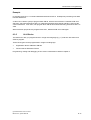
4.3
Access to the PII
At the start of cyclic program execution, the signal states of the digital inputs are read into the PII.
This ensures that the signal states remain unchanged during execution of the control program.
The PII can be accessed bit-, byte- and wordwise.
PII
7 6 5 4 3 2 1 0
Bitwise read
in binary operations:
A I
Bit no.
Byte 2
2.5
Bytewise read
in binary operations:
L IB
25
Byte 25
15
0
ACCUM
High.Byte
Low.Byte
(00H)
Wordwise read
in binary operations:
L IW 116
Byte 116
Byte 117
15
0
ACCUM
High.Byte
Figure 4. 2
4–2
Low.Byte
PII access
(4)J31069-D2037-U001-A3-7618
IMC0x-PLC, System Manual
I/O Addressing
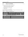
4.4
Access to the PIQ
At the end of cyclic program execution, the digital outputs are transferred from the PIQ to the
peripheral area. This avoids changes to output signal states caused by intermediate results from the
control program.
The PIQ can be accessed bit-, byte- and wordwise.
PIQ
7 6 5
Bitwise write
in binary operations:
4 3 2 1 0
Bit no.
Byte 3
= Q 3.3
Bytewise write
in binary operations:
T QB
14
Byte 14
15
0
ACCUM
High.Byte
Low.Byte
Wordwise write
in binary operations:
T QW 92
Byte 92
Byte 93
15
0
ACCUM
High.Byte
Figure 4. 3
PIQ access
4.5
Direct Access
Low.Byte
The IMC0x-PLC also allows direct accesses to inputs and outputs. The load operations L PB 0 to
L PB 127 or L PW 0 to L PW 126 access the digital inputs. The transfer operations T PB 0 to T PB 127
or T PW 0 to T PW 126 access the digital outputs. (The physical addresses are the same as for
operations with the operands IB 0 to IB 127 or QB 0 to QB 127.)
The operand areas PB 128 to PB 255 and QB 0 to QB 255 (or PW 128 to PW 254 and QW 0 to
QW 254) are used to access the extended peripheral area. Again, load operations select inputs and
transfer operations select outputs.
(4)J31069-D2037-U001-A3-7618
IMC0x-PLC, System Manual
4–3
I/O Addressing
Transfer operations to the peripheral bytes PB 0 to PB 127 simultaneously update the output process
image (PIQ). This prevents arbitrary resetting of the output when the PIQ is transferred to peripheral
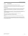
devices. The PII is, however, not updated by load operations.
physical addresses
DB 1
logical addresses
0 ... 127
128 ... 255
PII
A I x.x
L IB x
L IW x
L PB/PYx
L PWx
*
L PB/PYx
L PWx
*
T PB/PYx
T PWx
*
Control program
= Q x.x
T QB x
T QW x
T PB/PYx
T PWx
*
PIQ
0 ... 127
128 ... 255
logical addresses
physical addresses
DB 1
* PY for STEP 5 base package for PC
Figure 4. 4
Direct access to inputs/outputs
Address allocation is managed with entries in the data block DB 1.
4–4
(4)J31069-D2037-U001-A3-7618
IMC0x-PLC, System Manual
I/O Addressing
4.6
Initializing Outputs
The outputs of the IMC05 can be initialized during startup with initial values. There are different ways
in which blocks can be initialized:
•
initializing by DB 1 data block
•
initializing by SWCPLC.C
•
initializing in restart OB 22
Initializing by the DB 1 data block is described in chapter 9.
4.7
Access to Decentral Inputs/Outputs
With IMC05
The IMC0x-PLC uses the following calls of the RMOS-DP interface for data communication with the
decentral I/O stations. See also the technical description of IMC05-DP.
Com05DPStart()
Set up a DP entity
dpn_init()
Register a DP application
dpn_read_cfg()
Determine the configuration of the DP system
dpn_in_slv()
Read the input data of one DP slave
dpn_in_slv_m()
Read the input data of several DP slaves
dpn_out_slv()
Send output data to one DP slave
dpn_out_slv_m()
Send output data to several DP slaves
dpn_slv_diag()
Request diagnostic data of a slave
The process image is updated with dpn_in_slv_m() and dpn_out_slv_m(). The I/O bytes are
addressed with dpn_in_slv() and dpn_out_slv(). These calls require an execution time of 300
to 400 microseconds to access an I/O byte or I/O word.
Since only all inputs or outputs of one station can be read or written simultaneously, a read or write job
must be triggered for all I/O bytes of that station when direct I/O accesses (with L PY or T PY) are
used.
The I/O bytes written last are stored locally.
IMC0x-PLC supports up to 16 activated PROFIBUS-DP stations. A maximum of 32 bytes are
permitted per station.
The PROFIBUS-DP interface is designed as a driver. This ensures that only one job is processed at a
time when several requests by various tasks are made.
(4)J31069-D2037-U001-A3-7618
IMC0x-PLC, System Manual
4–5
I/O Addressing
With IMC01
With the IMC01, decentral I/O cannot be linked directly to the I/O area of the PLC (in contrast to
IMC05) since the IMC01 has a DP slave and not a DP master.
However, decentral I/O can be processed with the STEP 5 program. This means that a DP interface
must be included in the C program section of the application. See technical description of the
IMC01-BSP.
HLL function blocks can then be used to image the DP input and output areas in a PLC data block, for
example.
4–6
(4)J31069-D2037-U001-A3-7618
IMC0x-PLC, System Manual
Testing and Startup Functions
5
Testing and Startup Functions
The IMC0x-PLC supports all the test and startup functions of SIMATIC STEP 5 programmers:
•
Status block
•
Status variables
•
Forcing variables
•
Forcing outputs
•
Loading of blocks PLC ↔ PG
•
Deleting blocks
•
PC-START/STOP
•
Controller directory
•
Memory compression
•
Program-dependent signal state reporting
•
Process monitoring
•
Output of the interrupt stack (ISTACK)
•
Output of the block stack (BSTACK)
•
System parameter output
•
Address output
•
Display memory structure
These functions are described below. You will find more detailed information in the corresponding
programmer manual.
Communication between the PLC and PG is handled by the AS511 protocol using RS 232-2 of the
IMC05 or COM1 of the IMC01. See chapter 5 of the user manual. In the case of different interface
formats, you will have to use an interface converter.
Note:
Transfer speed for serial communication is set to 9600 baud.
5.1
Forcing Variables
This test function lets you change any process variables (operand area I, Q, F, D, T, C). The variables
are changed at the end of a processing cycle. It is not possible to influence signal states directly during
a cycle.
Controlling variables is primarily a way of modifying processing in RUN mode, but it can also be used
effectively in STOP mode. Changed variables are accepted at the RUN transition.
(4)J31069-D2037-U001-A3-7618
IMC0x-PLC, System Manual
5–1
Testing and Startup Functions
5.2
Forcing Outputs
This function lets you address outputs directly so as to test the wiring to peripheral components. You
can also check the allocation of logical output bytes to physical addresses (DB 1 configuration). The
IMC0x-PLC must be in STOP mode for this test function. All outputs used from the IMC0x-PLC then
are reset.
5.3
Compressing Memory
When a block of user memory is deleted, although it then no longer exists logically, it still takes up
memory space. The "Compress memory" function releases this space. Memory is also compressed
automatically every time the CPU is switched on (power-on reset).
Note:
When a compression is triggered by the PG, for example, this may change the physical address of
the data block. Keep this in mind when accessing a data block with a pointer from HLL blocks.
5.4
Direct Signal State Reporting (Status Variables)
While the controller is in RUN mode, this test function reports the state of any specified operand (I, Q,
F, D, T, C). The information is taken from the process image of the specified operand at the end of a
processing cycle. However, if an operand's signal state changes several times during the course of a
processing cycle, this fact cannot be registered by testing in this way.
In STOP mode, the operand area "digital inputs" is not read from the process image, but directly from
the inputs.
5.5
Program-dependent Signal State Reporting
This test function reports current signal states and RLO (result of logic operation) of individual
operands while program code is being processed.
In addition it lets you make corrections to the program. The controller must be in RUN mode for this
test function to operate.
5–2
(4)J31069-D2037-U001-A3-7618
IMC0x-PLC, System Manual
Testing and Startup Functions
5.6
Process Monitoring
This function lets you execute any code block in step mode. Calling this PG function causes program
processing to be halted at a specified point. You specify the halt point - an instruction in the program by positioning the cursor on it in the chapter of program code displayed on your monitor. Current
signal states and RLO, up to the specified instruction, are reported. By repeatedly moving the halt
point, you can process any STEP 5 code block step by step.
Process monitoring means that:
•
All jump commands are traced
•
Block calls are processed without delays. Process monitoring is resumed only after return.
At the end of the block (BE) program execution is automatically ended.
•
The process image is not updated from/to the inputs and outputs - outputs are set to zero. If the
controller is switched from STOP to RUN only after process monitoring has been activated, the
input process image is set to zero for the remainder of the program run.
5.7
Output of Interrupt Stack (ISTACK)
Outputting the ISTACK helps to determine the cause of a runtime error. Runtime errors are indicated
by setting the error flag. When a runtime error occurs, the controller switches to STOP mode (the
mode change includes a ISTACK entry) only if the appropriate error OB is not available, or if a STOP
instruction (STS) is programmed.
Note:
ISTACK output by the IMC0x-PLC does not comply completely with S5 conventions. See
chapter 15).
5.7.1
Determining the Error Source
The STEP 5 address counter (SAC) in the ISTACK specifies the absolute start address of the block in
which the runtime error occurred. However, the erroneous STEP 5 instruction in the block cannot
always be identified by means of this address. In this case the SAC indicates the start of the block
and the relative command counter (REL-SAC) will always contain the value 0.
The command register BEF-REG, however, contains the MC5 code of the STEP 5 instruction which
caused the runtime error. By consulting the table in the Reference Manual, chapter 2.6 you will be
able to identify the corresponding STL instruction.
Determining the error source is only relevant, if the error is one of the following:
•
substitution error
•
transfer error
(4)J31069-D2037-U001-A3-7618
IMC0x-PLC, System Manual
5–3
Testing and Startup Functions
5.7.2
ISTACK Output to PG
The following tables show the ISTACK of the IMC0x-PLC. In contrast to the PG, only the bits
mentioned here are significant. The bold encircled bits have a different meaning.
Table 5. 1
Control bit output
System
data word
Absolute
address
SD 5
EA0A
–
–
BSTSCH
SCHTAE
ADRBAU
–
–
–
EA0B
CA-DE
CE-DE
–
REMAN
–
–
–
–
EA0C
STOZUS
STOANZ
–
–
–
–
BARB
BARBEND
SD 6
SD 7
Control bits
7
0
EA0D
–
–
MAFEHL
EOVH
–
AF
–
–
EA0E
ASPNEP
ASPNRA
–
–
ASPNEEP
–
–
–
EA0F
KEINAS
–
–
–
–
–
–
URLAD
– = not used
Absolute
address
System
data word
Interrupt stack
Depth: 01
EB9A ...
EBA0
SD205 ...
SD208
BEF-REG:
BST-STP:
0000
EB07
SAZ:
OB-Nr.:
REL-SAZ:
E30A
1
0000
EB96 ...
EB98
SD203 ...
SD204
ACCUM 1:
FFF1
ACCUM 2:
00FF
EBA2 ...
EBA8
SD209 ...
SD212
Brackets:
EBAA
SD213
Display of
result
EBAC
SD214
KE1: 000
KE2: 000
KE3: 000
DB-ADR:
DB-Nr.:
KE4: 000
KE5: 000
0000
KE6: 000
CC 1
CC 0
OVFL
CARRY
OR
STATUS
RLO
ERAB
STOPS
-
SUF
TRAF
NNN
STS
STUE
FEST
NAU
QVZ
-
ZYK
-
PEU
BAU
ASPFA
Cause of
fault:
EBA9
Figure 5. 1
5–4
(UAW)
ISTACK output
(4)J31069-D2037-U001-A3-7618
IMC0x-PLC, System Manual
Testing and Startup Functions
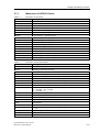
5.7.3
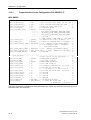
Mnemonics of ISTACK Entries
Table 5. 2
Mnemonics of control bits
Abbreviation
Meaning
SD
System data (from address EA00h)
BSTSCH
Block move requested
SCHTAE
Block move active (function KOMP:AG)
ADRBAU
Address list creation
CA-DA
Communication output flags - address list available
CE-DA
Communication input flags - address list available
REMAN
0: no retentivity, 1: retentivity active
STOZUS
STOP state (external request)
STOANZ
STOP display (internal request)
BATPUF
Battery buffering ok (always 1)
BARB
Process monitoring
BARBEND
Process monitoring end request
AF
Alarm enabled
ASPNEP
User memory is EPROM
ASPNRA
User memory is SRAM (buffered)
ASPNEEP
User memory is file
KEINAS
User memory is RAM (unbuffered)
Table 5. 3
Mnemonics of interrupt indications
Abbreviation
Meaning
UAW
Interrupt indicator word
STOPS
Operating mode switch at STOP
SUF
substitution error
TRAF
Transfer error during data block commands: DW number > DB length
STS
Operation interrupted by PG STOP request or STOP instruction
STUEB
Block stack overflow: maximum nesting depth (32) exceeded
QVZ + ZYK
Timer error: processing time for timer OB too long
ZYK
scan time exceeded
ASPFA
Invalid memory module
CC 1 / CC 0
00: ACCUM1 = 0 or 0 moved
01: ACCUM1 > 0 or 1 moved
10: ACCUM1 < 0
OVF
Arithmetic overflow (+ or –)
OR
OR memory (set by command "O")
STATUS
Status of command operand of last executed binary command
RLO
Logical result of operation
ERAB
Initial request
KE1 ... KE6
Bracketed stack entry 1 to 6 entered for A( and O(
FKT
0:
1.
BEF-REG
Command register
1)
O(
A(
SAC
Step address counter
DB-ADR
Data block address
(4)J31069-D2037-U001-A3-7618
IMC0x-PLC, System Manual
1)
5–5
Testing and Startup Functions
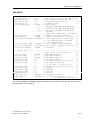
Table 5. 3
Mnemonics of interrupt indications
Abbreviation
Meaning
BST-STP
Block stack pointer
OB-NR
Organization block number
DB-NR
Data block number
REL-SAC
Relative step address counter
1)
The results in STATUS and ERAB will not be influenced
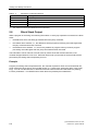
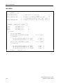
5.8
Block Stack Output
While a program is executing, the following information on each jump operation is entered in the block
stack:
•
the data block which was being processed before the jump command,
•
the relative return address, i.e., the address at which program processing must start again after
the jump command has been executed,
•
the absolute return address, i.e., the memory address in program memory at which program
processing must start again after the jump command has been executed.
This information can be read out in STOP mode by means of the PG function BSTACK, if the
controller stopped because of an error. BSTACK will thus tell you the state of the block stack at the
point where processing was interrupted by an error.
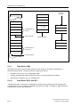
Example
Program processing was interrupted at FB 2, the controller reported a TRAF error and switched into
STOP mode (the cause was an incorrect DB access, e.g., DB 5 is two words long, DB 3 is ten words
long). You can use the BSTACK, to determine how FB 2 was reached and which block is passing
incorrect parameters. The BSTACK will contain the three (marked) return addresses.
5–6
(4)J31069-D2037-U001-A3-7618
IMC0x-PLC, System Manual
Testing and Startup Functions
PB 1
00
xx
Interrupt with error message "TRAF"
BE
PB 4
OB 1
PB 2
00
00
00 C DB5
02
02 JU PB4
02 JC FB2
04
04
10
06
xx
BE
xx
BE
FB 2
08
10
2A L DW4
PB 3
xx
BE
00 C DB3
xx
16
18
Figure 5. 2
BE
BE
Monitoring program processing via the BSTACK
(4)J31069-D2037-U001-A3-7618
IMC0x-PLC, System Manual
5–7
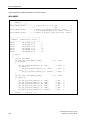
Testing and Startup Functions
Display
* B S T A C K
Block type and
block number
B L O C K
P B
P B
O B
4
2
1
R E L. A D D R
0
0
0
0
0
0
0
5
1
0
0
0
0
4
6
5
DB
5
5
5
Relative
return address
Insignificant codes
Figure 5. 3
Number of current
data block
Example of a BSTACK readout
The entry shows that a DB 5 was erroneously accessed via OB 1 → PB 2 → PB 4.
5–8
(4)J31069-D2037-U001-A3-7618
IMC0x-PLC, System Manual
Testing and Startup Functions
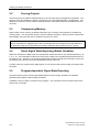
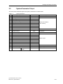
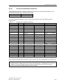
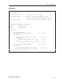
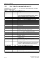
5.9
System Parameter Output
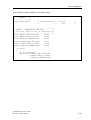
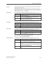
The PG function SYSPAR reports the system parameters as shown below.
Table 5. 4
No
System parameters
System parameters
Content
Explanation
1
Baud rate
9600
2
Input signal states
F000
3
Output signal states
F080
4
Input process image
EF00
5
Output process image
EF80
Absolute start address
6
Flag area
EE00
in CPU memory
7
Timer area
EC00
8
Counter area
ED00
9
SD area
EA00
10
PLC software release
9F03
11
Program memory
D800
12
System memory
0000
13
DB list
0200
14
Bytes in SB list
0200
15
PB list
0200
16
FB list
0200
17
OB list
0200
18
FX list
0000
19
DX list
0000
20
Length of DB 0
0A00
21
2nd CPU identification
EF04
22
Block header length
23
CPU identification
(4)J31069-D2037-U001-A3-7618
IMC0x-PLC, System Manual
000A
PG software
release
Baud
End address
Length in bytes
Length in bytes
U000
5–9
Testing and Startup Functions
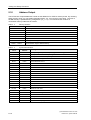
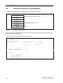
5.10
Address Output
The PG function "Output addresses" reads out the IMC0x-PLC's STEP 5 memory areas. By checking
these memory areas, you can obtain information about, e.g., error sources cycle times. The size of
the DB memory is specified during configuration (db_size). The PG shows the contents of
nonexistent memory addresses as "XXXX".
Table 5. 5
Memory allocation
Absolute address
Content
0000H ... CFFFH
DB memory
DC00H ... E5FFH
Block address list
EA00H ... EBFFH
System data blocks
EC00H ... ECFFH
Timers
ED00H ... EDFFH
Counters
EE00H ... EEFFH
Flags
EF00H ... EFFFH
PII/PIQ, process images
F200H ... F2FFH
Communication flags in shared memory
Table 5. 6
System data
word
System data allocation
Absolute
address
Meaning
SD 16 ... 31
EA20 ... EA3F
Bitmap for logical inputs and outputs (digital and analog)
SD 64 ... 79
EA80 ... EA9F
Bitmap for communication output flags
SD 80 ... 95
EAA0 ... EABF
Bitmap for communication input flags
SD 96
EAC0
Scan time monitoring
SD 97
EAC2
Time interval for OB 13
SD 98
EAC4
Time interval for OB 12
SD 99
EAC6
Time interval for OB 11
SD 100
EAC8
Time interval for OB 10
SD 104
EAD0
Error status word
SD 105
EAD2
Error DW number
SD 106
EAD4
Error DB number
SD 107
EAD6
Error PB number
SD 108
EAD8
Error SB number
SD 109
EADA
Error FB number
SD 110
EADC
Error OB number
SD 111
EADE
Error opcode
SD 121
EAF2
Current scan time
SD 122
EAF4
Maximum scan time
SD 123
EAF6
Minimum scan time
SD 124 ... 126
EAF8 ... EAFD
PROFIBUS-DP diagnostics
SD 128 ... 201
EB00 ... EB93
Block stack
SD 203 ... 238
EB96 ... EBDD
Interrupt stack
SD 240 ... 243
EBE0 ... EBE7
Reserved
SD 248 ... 255
EBF0 ... EBFF
Reserved for user programs
5–10
(4)J31069-D2037-U001-A3-7618
IMC0x-PLC, System Manual
Testing and Startup Functions
5.11
Display Memory Structure
This function displays the structure and allocation of STEP 5 program memory (MC5 code). Because
the memory is divided into two segments, if you call this function more than once, the display will show
MC5 memory and DB memory alternately.
Note:
Different PGs might show differing values in the memory structure display. The IMC0x-PLC gives
correct values for the basic package STEP 5 from Version 6.5 or 7.02.
5.12
Error Reporting with the Error Status Word
The error status word SD 104 (address EAD0) is used to report IMC0x-PLC-specific errors.
Information on the cause of the error is entered in the system data words SD 105 to SD 111. These
system data words can be read out with the PG function "Output addresses". For Details on the error
status word see chapter 3.8.3.
(4)J31069-D2037-U001-A3-7618
IMC0x-PLC, System Manual
5–11
Testing and Startup Functions
5–12
(4)J31069-D2037-U001-A3-7618
IMC0x-PLC, System Manual
Introduction to Programming
6
Introduction to Programming
This chapter is a general introduction to writing controller programs for the IMC0x-PLC. It covers basic
programming skills and discusses modular program structures using different types of blocks.
6.1
STEP 5 Programming Language
STEP 5 is a programming language especially developed for writing programs to operate the
controllers used in automation technology. STEP 5 is a versatile language allowing you to program
operations ranging from simple binary functions to complex digital functions and basic arithmetic
operations.
6.1.1
Display Modes
A STEP 5 program for the IMC0x-PLC is written in one of three different ways or "display modes". The
mode you chose usually depend on the job you are automating.
Statement list (STL)
With a STL, the program to be executed is written as a list of (abbreviated)
commands. A command has the following structure:
Operation
Operand
002:
A I
0.1
Parameter
Operand code
Relative address of statement in block
The operation tells the controller what to do with the operand. The parameter
supplies the address of the operand.
Control system flow
chart (CSF)
In flow chart representation, the program is written as a series of logical
operations depicted as boxes.
Ladder diagram
(LAD)
In a LAD, the program is graphically represented by the symbols used in
power supply diagrams.
Programs in CSF and LAD representation can be written only on a programmer with an integrated
monitor (e.g., a PG 750 or PC/AT with the necessary software).
(4)J31069-D2037-U001-A3-7618
IMC0x-PLC, System Manual
6–1
Introduction to Programming
The diagram below shows the same logical AND operation, to solve a very simple automation
problem, in the three display modes STL, CSF and LAD:
•
a signal lamp must light up when the make contact S1 is activated and the break contact S2 is
not activated.
•
for the controller in the example, the make contact S1 is tested via input I1.1 and the break
contact S2 is tested via the input I1.2. The signal lamp is controlled via output Q2.0.
Circuit diagram
STL
LAD
CSF
S1
I 1.1
S2
Figure 6. 1
A
I 1.1
A
I 1.2
=
Q 2.0
I 1.1
I 1.2
Q 2.0
&
I 1.2
Q 2.0
Display modes
You can chose the best display mode for the control task you are programming. It is also possible to
write separate program blocks in different representation, i.e., you do not have to write the whole
program in a single mode.
Each mode has advantages and disadvantages. STL is the most versatile display mode, but a block
programmed in STL cannot always be simply translated into CSF or LAD. On the other hand, blocks
programmed in LAD or CSF are easily changed into STL.
In STEP 5 there are three types of operations:
•
basic operations
•
extended operations
•
system operations
6–2
(4)J31069-D2037-U001-A3-7618
IMC0x-PLC, System Manual
Introduction to Programming
Table 6. 1
Features of the operation types
Basic operations
Extended operations
System operations
Application scope
All blocks
Function blocks only
Function blocks only
Display modes
STL, CSF, LAD
STL
STL
Criterion
For users with good
system knowledge
You will find detailed information on the different operation types in the Reference Manual, chapter 2.
6.1.2
Operand Areas
STEP 5 programming uses the following operand areas:
I (inputs)
Interfaces from the process to the controller via PII
Q (outputs)
Interfaces from the controller to the process via PIQ
F (flags)
Memory for binary intermediate results
D (data)
Memory for digital intermediate results
T (timers)
Register for programming timers
C (counters)
Register for programming counters
P (peripherals)
Direct interface between process and controller (not via the process image)
K (constants)
Fixed number values
The operands in an operand area are identified by specific extensions:
IB 7
denotes, e.g., the 7th input byte of the PII
Q 3.2
denotes, the 2nd bit in the 3rd output byte of the PIQ
KF
denotes, a fixed-point numeric constant (16-bit integer)
A list of all operations and operands can be found in the Reference Manual, chapter 3.
6.2
Program Structure
Control programs can be linear or structured. These two approaches are explained below.
6.2.1
Linear Programming
For simple control tasks, it is often sufficient to write a control program only in the organization block
OB 1. During processing the OB 1 is called cyclically by the controller.
Note that OB 1 length is restricted to 4096 words, thus limiting the length of the control program.
(4)J31069-D2037-U001-A3-7618
IMC0x-PLC, System Manual
6–3
Introduction to Programming
6.2.2
Structured Programming
To solve complex automation problems, the program is split up into a number of separate modules or
blocks.
There are several advantages:
•
long programs can be broken down into simple and easily understandable units
•
blocks can be standardized
•
blocks which have tested successfully can be used again in other programs. This applies
especially to function blocks (FB)
•
self-contained blocks are easier to test and debug
•
making changes is simplified
•
startup is easier
•
subprogram techniques can be used (e.g., a block can be called from several different points in
the program)
Structured programs can include the following block types:
•
Organization block (OB)
Organization blocks manage the control program. They form an interface between the
controller's internal operations and the user's control program. OBs manage, inter alia, cyclic
program execution, initialization of the control system or handling of runtime errors (see Table 6.
3).
•
Program block (PB)
Program blocks are the self-contained modules which make up a PLC program. These blocks
are called by commands in OBs or FBs. Parameter passing is not possible with PBs. Data can
only be transferred to a PB via a data block.
•
Sequence blocks (SB)
Sequence blocks are a special type of program block which contain the program for a sequencer.
They are treated like program blocks.
•
Function blocks (FB)
Function blocks are used to program operations which recur frequently. A FB can be called from
an OB, PB or another FB. An FB call can be parametrized, i.e., parameters can be passed with
the call.
•
Data blocks (DB)
Data blocks contain STEP 5 data needed by the control programs. Typically these data are set
values, limiting values or text. Data blocks are also used to pass parameters for PBs.
Block calls are statements which invoke other blocks, causing a jump to the specified block.
Organization, program, function and sequence blocks can be nested up to 32 deep.
Note:
When you are calculating nesting depth, remember that some organization blocks are called
automatically (e.g., when a runtime error occurs).
Total nesting depth is the sum of the nesting depths of all the blocks in a program. If the nesting depth
exceeds 32, the controller reports a "block stack overflow" (STUEB) and goes into STOP mode.
6–4
(4)J31069-D2037-U001-A3-7618
IMC0x-PLC, System Manual
Introduction to Programming
OB 1
FB 1
PB 5
PB 10
PB 184
...
PB 6
PB 22
Level 1
Level 2
Level 3
Figure 6. 2
Nesting depth
6.3
Blocks and their Attributes
...
FB 13
...
Level 32
The table below sets out the most important information you will need about blocks:
Table 6. 2
Block types
OB
PB
SB
FB
DB
255
OB 1 ... 255
256
PB 0 ... 255
256
SB 0 ... 255
256
FB 0 ... 255
254
DB 2 ... 255
Length (max)
8 Kbytes
8 Kbytes
8 Kbytes
8 K –8 bytes
2 Kwords
Operation set
(content)
Basic
operations
Basic
operations
Basic
operations
Basic
operations
Number
1)
2)
3)
Bit patterns,
numbers, texts
Extended
operations
System
operations
Display modes
STL, CSF, LAD STL, CSF, LAD STL, CSF, LAD
STL
4)
4)
Block header length
5 words
5 words
5 words
5 words
Block calls
JU, JC
JU, JC
JU, JC
JU, JC
1)
OBs in particular are called by the IMC0x-PLC itself (see Table 6. 3)
2)
Data blocks DB 0 and DB 1 are reserved.
Q, I
3)
STEP 5 commands only access the data words DW 0 to DW 255.
4)
Blocks OB 208 to OB 223 and FB 208 to FB 223 may also be programmed in high level languages.
The maximum length for each block is 4096 words (8 Kbytes). A block consists of a header and a
body. The block header is 5 words long and contains information on the block type, number and
length. The PG creates this header when the block is programmed. Depending on the type of block,
the block body will contain STEP 5 program code or user data. Function blocks have not only a
header, but also additional information for passing parameters.
(4)J31069-D2037-U001-A3-7618
IMC0x-PLC, System Manual
6–5
Introduction to Programming
6.3.1
Organization Blocks (OB)
The organization blocks OB 1 to OB 39 are the interface between the control program and the
controller's internal operations.
The controller processes OBs either event- or timer-driven. OBs are grouped according to their
function as follows (see also chapter ):
•
OBs for restart program processing
•
OB for cyclic program processing
•
OBs for timer-driven program processing
•
OBs for handling runtime errors
For details on operating modes, see chapter 3.
Table 6. 3
Overview of organization blocks
Organization block
Function
Meaning
OB 1
Cycle OB
Cyclic program scanning
OB 2
–
Reserved for future applications
OB 3
–
Reserved for future applications
OB 4
–
Reserved for future applications
OB 5
–
Reserved for future applications
OB 10
Timer OB
Timer-driven program scanning
OB 11
Timer OB
Timer-driven program scanning
OB 12
Timer OB
Timer-driven program scanning
OB 13
Timer OB
Timer-driven program scanning
OB 19
Error OB
call of nonexistent block
OB 21
Restart OB
STOP → RUN operating mode switch
OB 22
Restart OB
STOP → RUN operating mode transition after power-on
OB 26
Error OB
scan time exceeded
OB 27
Error OB
substitution error
OB 28
STOP OB
RUN → STOP operating mode switch
OB 31
Trigger OB
Scan time triggering
OB 32
Error OB
Transfer error
OBs not listed here are reserved and may be assigned functions in future program versions. They
should not be used for user control programs.
6.3.1.1
Programming Organization Blocks
Organization blocks can be programmed in STL, CSF or LAD. They are programmed in the same way
as program blocks. The organization blocks OB 208 to OB 223 can also be programmed in high level
language (see chapter 8). Every organization block, including OB 1, must end with the operation BE.
6.3.1.2
Calling Organization Blocks
Organization blocks can be called, like program blocks from any other block. Conditional and
unconditional calls are possible. Note that certain OBs are initialized with particular functions.
6–6
(4)J31069-D2037-U001-A3-7618
IMC0x-PLC, System Manual
Introduction to Programming
6.3.2
Program Blocks (PB) and Sequence Blocks (SB)
Program blocks are the separate modules of a PLC program. These blocks are called by commands
in OBs or FBs. Parameter passing is not possible with PBs. Data can only be transferred to a PB via
a data block.
Sequence blocks are a special type of program block which contain sequencer program code. They
are treated like program blocks.
6.3.2.1
Programming PBs and SBs
The following description also applies to programming OBs. PBs, SBs and OBs are all programmed in
the same way. Under STEP 5 they can be programmed in STL, LAD and CSF representation. You
start writing a program by entering a block number on the PG:
•
Program blocks
•
Sequence blocks 0 to 255
•
Organization blocks
0 to 255
1 to 39
Then you enter your control program. It must end with the instruction BE. You are restricted to the
basic STEP 5 operation set. The STEP 5 program code for each block may not take up more than
4091 words in program memory, because the block header which is automatically generated by the
PG always takes up 5 words.
Each block should be a self-contained program. Logical operations across block boundaries are not
meaningful.
0
PB 25
Block header
5
1st STEP 5 instruction
STEP 5 program
BE
available block length
4095
Figure 6. 3
Structure of an organization or program block
6.3.2.2
Calling Program and Sequence Blocks
A block call releases a block for processing. Block calls can be programmed in organization, program,
function or sequence blocks. A block call is comparable to a jump to a subprogram and, like jumps,
can be conditional or unconditional.
(4)J31069-D2037-U001-A3-7618
IMC0x-PLC, System Manual
6–7
Introduction to Programming
PB 1
PB 5
JU PB5
O I5.3
PB 10
A I1.0
JC PB10
A I2.0
BE
BE
PB 6
A I1.5
JC PB6
A I3.2
BE
Figure 6. 4
Block calls
When the controller encounters the command BE (block end), it performs a jump back to the block
containing the block call, and continues processing with the STEP 5 command immediately following
the block call. After a block call and also after a BE command, the result of logic operation (RLO)
cannot be combined further, because both these commands are RLO-limiting commands.
•
Unconditional call: JU xx
The specified block is processed, independent of the result of the previous logic operation.
•
Conditional call: JC xx
Whether the specified block is processed or not, depends on the result of the previous logic
operation.
If RLO = 1 the jump command is executed, if RLO = 0 it is not. In both cases the jump command
causes RLO to be set to 1. This dependence on RLO and change of RLO also applies to the
conditional block end command BEC.
6.3.3
Function Blocks (FB)
Function blocks are used to program control functions which either recur frequently or are complex.
Function blocks have some special characteristics which distinguish them from organization, program
and sequence blocks:
•
Function blocks can be parametrized, i.e., the block call can include parameters.
•
Function blocks can execute extended operations and system operations.
•
Function blocks may be written and documented only as STL (statement list), with the exception
of certain FBs which may be written in HLL.
6–8
(4)J31069-D2037-U001-A3-7618
IMC0x-PLC, System Manual
Introduction to Programming
The controller has the following function blocks available:
•
FB 0 to FB 207 for programming in STEP 5
•
FB 208 to FB 223 for programming in assembler or high level languages (see chapter 8)
•
FB 224 to FB 255 are reserved for future use as integrated function blocks.
FB 208 to FB 255 can be programmed in STEP 5, if necessary. However, this option should not be
used, so as to avoid conflicts with HLL blocks or integrated function blocks.
In addition to the block header common to all blocks, function blocks contain other organizational
information.
Memory requirements for the block header plus the additional information are as follows:
•
Block header, as for other block types (5 words)
•
Block name (5 words)
•
Block parameters if assigned (3 words per parameter).
(4)J31069-D2037-U001-A3-7618
IMC0x-PLC, System Manual
6–9
Introduction to Programming
6.3.3.1
Programming Function Blocks
In contrast to other blocks, a function block can contain additional information such as:
•
Library number
The block can be given a number between 0 and 65535. This number is completely independent
of symbolic or absolute FB parameters.
A library number should be a unique number which identifies a particular function block
unambiguously. Standard function blocks already have their own product number.
•
Name
A function block can be identified by a name up to eight characters long.
To assign parameters you must supply the following block parameter data:
•
Block parameter name (formal operands)
Each block parameter is given a name (DECL) which is used as the formal operand in a function
block call and is replaced by an actual operand during program execution. The block parameter
name may have up to four characters, the first of which must be an alphabetic character. You
can program up to 40 parameters per function block.
•
Block parameter type
These are the possible parameter types:
I Input
Q Output
D Date
B Block
T Timer
C Counter
In graphical representation, output parameters are shown to the right. All other parameters to the
left of the function symbol.
•
Data type
These are the possible data types:
BI for an operand with bit address
BYfor an operand with byte address
W for an operand with word address
K for constants
When assigning parameters all three block parameter specifications must be entered.
6–10
(4)J31069-D2037-U001-A3-7618
IMC0x-PLC, System Manual
Introduction to Programming
Block header
Name
NAME: EXAMPLE
Block parameter
DCL:
IN1
I BI
DCL:
IN2
I BI
DCL:
OUT1 Q BI
Parameter
Name (formal operand)
Format
...
:A = IN1
:A = IN2
:= = OUT1
...
Control program
Memory allocation
Type
Program example
Figure 6. 5
Programming an FB with block parameters
Table 6. 4
Parameter type and data type of block parameters with permitted actual operands
Parameter
type
Parameter format
Permitted actual operands
I, Q
BI
Operands with bit address
I
Q
F
x.y
x.y
x.y
Input
Output
Flag
BY
Operands with byte address
IB
QB
FB
DL
DR
PB
x
x
x
x
x
x
Input byte
Output byte
Flag byte
Left data byte
Right data byte
Peripheral byte
W
Operands with word address
IW
QW
FW
DW
PW
x
x
x
x
x
Input word
Output word
Flag word
Data word
Peripheral word
D
KM Binary bit pattern (16 bits)
KY
Constants
Two absolute values (bytes in the range
of 0 to 255)
KH Hexadecimal value (max. 4 digits)
KS
max. 2 alphanumeric characters
KT
BCD-coded time value (1.0 to 999.3)
KC BCD-coded counter value (0 o 999)
KF
Fixed-point value (–32768 o +32767)
(4)J31069-D2037-U001-A3-7618
IMC0x-PLC, System Manual
6–11
Introduction to Programming
Table 6. 4
Parameter type and data type of block parameters with permitted actual operands
Parameter
type
Parameter format
Permitted actual operands
b
No parameter format
DB x
Data block, called with command
C DBx
FB
x
Function blocks (only valid without
parameters), called absolutely
(JU FBx)
PB
x
Program blocks, called absolutely
(JU PBx)
SB
x
Sequence blocks, called absolutely
(JU SBx)
T
No parameter format
T
Timer: the value is parametrized as
data or programmed as constant in
the function block
C
No parameter format
C
Counter: the value is parametrized
as data or programmed as
constant in the function block
Programming FBs in HLL is described in detail in chapter 8.
6.3.3.2
Calling Function Blocks
A function block is stored in program memory under a particular number - as are all other types of
block - (e.g., FB 47).
Calls to FBs can be included in any block, with the exception of data blocks.
The call consists of:
•
Call instruction
JU FBx
unconditional call
JC FBx
call if RLO = 1
•
Parameter list (only if parameters are assigned)
Function blocks programmed in HLL are called in the same way as function blocks programmed in
STL.
Function blocks have to be programmed before they can be called. When you are programming an
FB call, the PG will automatically ask for the FB parameters.
6–12
(4)J31069-D2037-U001-A3-7618
IMC0x-PLC, System Manual
Introduction to Programming
6.3.3.3
Parametrization
The program in the function block specifies how the operands are processed.
After the jump instruction, the operands which the FB is to use (i.e., parameter list) must be specified
in the block in which the FB is called. The valid operands are also called the current operands.
Parameter list
Immediately following the jump instruction, the input and output variables and other data are defined,
i.e., each formal operand is supplied with an actual operand. The length of this parameter list will
depend on the number of formal operands. Thus a parameter list can contain up to 40 actual
operands.
As explained above, when the function block is executed, each formal operand is replaced by an
actual operand supplied by the parameter list. The PG automatically keeps track of the order in which
variables are substituted.
Figure 6. 6 gives an example of how parameters are assigned to a function block.
Other special characteristics of function blocks
The FB call takes up two words of program memory and each parameter takes up one word of
memory.
The identifiers for function block inputs and outputs and their names are stored in the function block
itself. For this reason, before you start programming on the PG, all the function blocks you will be
using in your program must have been loaded to the program diskette (for offline programming) or into
the controller's program memory.
(4)J31069-D2037-U001-A3-7618
IMC0x-PLC, System Manual
6–13
Introduction to Programming
PB 3
FB 5
Executed
program
NAME :EXAMPLE
:JU FB5
DCL
:X1 I BI
DCL
:X2 I BI
DCL
:X3 Q BI
NAME :EXAMPLE
X1
:I4.1
X2
:F1.3
X3
:Q0.1
:A = X1
:A = X2
:= = X3
Parameter list for
first call
Aktual operands
:BE
A
I4.1
A
F1.3
=
Q0.1
A
I4.5
A
I5.3
=
Q0.1
Formal operands
A I5.2
:JC FB5
NAME :EXAMPLE
X1
:I4.5
X2
:I5.3
X3
:Q0.1
Parameter list for
second call
Formal operands
Figure 6. 6
Parameter assignment for a function block
6.3.4
Data Blocks (DB)
Data blocks are used to store the data needed in a user program. No STEP 5 operations are
performed in data blocks. The data entered in a data block may be:
•
bit patterns of any sort, e.g., for aggregate states
•
numbers (hexadecimal, fixed point) for time values, results of arithmetic operations
•
alphanumeric characters, e.g., for message texts
6.3.4.1
Data Blocks DB 0 and DB 1
The data block DB 1 is reserved for initialization functions and must therefore be generated before
controller startup. You can find more detailed information on the DB 1 in chapter 9. Data block DB 0
is generally not used for the IMC0x-PLC.
6–14
(4)J31069-D2037-U001-A3-7618
IMC0x-PLC, System Manual
Introduction to Programming
6.3.4.2
Generating Data Blocks
To generate a data block you start by entering a data block number (e.g., DB 25). A data block is
made up of 16-bit data words, which are entered, beginning with data word 0, in ascending order.
PB 25
Block header
DW 0
4
A
3
2
DW 1
3
F
4
A
DW 2 0110 0100 0000 1111
DW 3
’Z’
’U’
Data words
DW n
Figure 6. 7
Structure of a data block
Each data word occupies one word of program memory. In addition, the PG generates a block header
for each data block , which takes up a further five words of program memory. A data block may
occupy a maximum of 4096 words in the controller's program memory. If a PG is being used for input
and transfer, the size of the PG's memory must also be considered.
Warning:
Load/transfer commands L/T DW ... can access data up to data word number 255 only. Data blocks
DB 0 and DB 1 are reserved and may not be called by user programs.
6.3.4.3
Calling Data Blocks
Data blocks can only be called unconditionally. Once a data block has been called, this block remains
valid until a new data block is called. A data block (DB) is called from an OB, PB, SB or FB with the
command C DB ... .
Warning:
Before a data word load/transfer can be executed, a data block must have been opened. The data
word being addressed by the command must be in the opened data block. If these conditions are
not met, a transfer error is reported (see chapter 3.8.1).
Example
Transfer the contents of data word 1 from data block DB 10 to data word 1 of data block DB 20.
(4)J31069-D2037-U001-A3-7618
IMC0x-PLC, System Manual
6–15
Introduction to Programming
DB 10
:C
:L
:C
:T
DB10
DW1
DB20
DW1
DW 0
DW 1
DW 255
DB 20
DW 0
DW 1
DW 255
Figure 6. 8
Addressing a data block
PB 7
C DB10
PB 20
C DB10
C DB11
JU PB20
BE
BE
Valid range of DB 10
Valid range of DB 11
Figure 6. 9
Valid range of a called data block
A command in a program block has addressed a data block. A subsequent command in the program
block causes a jump to another program block and from this second program block a second data
block is addressed. The second data block is valid only for the second program block. As soon as this
second PB is exited with a jump back to the first PB, then the first data block is valid again
6–16
(4)J31069-D2037-U001-A3-7618
IMC0x-PLC, System Manual
Introduction to Programming
Example
In program block PB 7, a command addresses data block DB 10. Subsequent processing uses data
from this data block.
A call in PB 7 causes a jump to program block PB 20, which is then executed. Data block DB 10 is
still valid. Only when data block DB 11 is called does the data area change and DB 11 become the
current data block. From then, until program block PB 20 has finished executing, data block DB 11 is
valid.
When execution jumps back to program block PB 7, data block DB 10 is valid again.
6.3.5
HLL Blocks
The IMC0x-PLC lets you program blocks in a high level language (e.g., C) and then link them into a
STEP 5 program.
These block types can be programmed in a high level language:
•
Organization blocks OB 208 to OB 223
•
Function blocks FB 208 to FB 223
Programming, testing and debugging of HLL blocks is described in detail in chapter 8.
(4)J31069-D2037-U001-A3-7618
IMC0x-PLC, System Manual
6–17
Introduction to Programming
6.4
Representing Numbers
STEP 5 lets you represent numbers in the following ways:
•
Decimal numbers from -32768 to +32767 (KF)
•
Hexadecimal numbers from 0000 to FFFF (KH)
•
BCD coded numbers from 0000 to 9999
•
Bit patterns (KM)
•
Byte constant (KY) from 0,0 to 255,255
Internally, the IMC0x-PLC converts all numbers to 16-bit binary numbers (bit patterns). Negative
numbers are represented as two's complement.
Table 6. 5
Organization of a 16-bit fixed-point number
Word number
n
Byte number
n (high byte)
Bit number
15
Meaning
2
Table 6. 6
15
14
2
14
13
2
13
12
2
12
11
2
11
n +1 (low byte)
10
9
8
7
6
5
4
3
2
1
0
10
2
9
2
8
2
7
2
6
2
5
2
4
2
3
2
2
2
1
2
2
Examples of the controller’s representing of numbers
Input value
Representation in the PLC
KF –50
1111 1111 1100 1110
KH A03F
1010 0000 0011 1111
KY 3,10
0000 0011 0000 1010
6–18
0
(4)J31069-D2037-U001-A3-7618
IMC0x-PLC, System Manual
STEP 5 User Memory
7
STEP 5 User Memory
For the debugging and startup phase, the PG loads a STEP 5 program into the controller's SRAM
memory. Completed and debugged programs are copied to EPROM.
User memory is split into two areas:
•
MC5 memory for MC5 program code
•
DB memory for retentive data and data blocks
Type and size of user memory are configurable and the IMC0x-PLC must include this information for a
configured PLC. You can find more information on configuration in chapter 10.
7.1
MC5 memory
This is MC5 memory for SIMATIC S5-115U compatible MC5 code. The maximum size is 32 Kb. The
following memory types are supported:
•
EPROM:
The MC5 code is entered in EPROM. Individual blocks can be loaded by the PG into the memory
area which is otherwise reserved for data blocks.
•
SRAM:
MC5 code is loaded by the PG.
•
Memory area not available:
MC5 code is loaded by the PG into the memory area which is otherwise reserved for data blocks
(only recommended for controllers of limited size).
For details on this memory types see chapter 10.1.
7.2
DB memory
This is the memory area for retentive data and data blocks. The size is configurable between 4 Kbytes
and 32 Kbytes. If the MC5 memory is located in EPROM, this memory can also be used to load
program blocks. The following memory types are supported:
•
SRAM:
A power failure, or switching off the power supply, will not result in loss of the retentive data and
data blocks in this memory. During PG restart after power-up, the integrity of the retentive data is
checked. If a data loss has occurred, an overall reset request is issued.
•
Dynamically requested RAM, retentivity not available.
At restart the whole retentive memory area is deleted. Data blocks must be generated new each
time by the control program, or loaded by the PG.
(4)J31069-D2037-U001-A3-7618
IMC0x-PLC, System Manual
7–1
STEP 5 User Memory
7.3
Memory Organization
During a restart, data blocks in MC5 memory are copied into DB memory and may then be modified
during subsequent program execution. The changes remain in force until the block is
deleted/overwritten. If the block in question is already present in DB memory then no copy operation
is performed. Data blocks which are generated during program execution (with I DB), are also located
in DB memory.
7.4
Conversion Program CVSTEPV.EXE
Conversion program CVSTEPV.EXE is used to convert a program file generated with STEP 5 into a
binary file with the memory image of the MC5 code. This binary file is transferred to a free, sufficiently
dimensioned memory segment of the user flash memory of the IMC05.
CVSTEPV.EXE generates a 16-bit format file.
Sign-on message
CVSTEPV Vx.y
STEPV FILE CONVERSION
Call syntax
CVSTEPV <source file> [<destination file>] [/e] [/l] [/s]
Option /e
Generate EPROM block type
When conversion as RAM block type is used, the DBs are loaded from the
current MC5 code during the restart after POWER OFF.
Note:
The /e option is mandatory for both the IMC05 and the IMC01.
Option /s
The file is split into LOW byte and HIGH byte.
Note:
The /s option cannot be used for either the IMC05 or the IMC01.
If no destination file is specified, the source file name is used with the extension BIN or LOW/HIG.
Example
CVSTEPV STEPTEST.S5D /e
generates the file STEPTEST.BIN
7–2
(4)J31069-D2037-U001-A3-7618
IMC0x-PLC, System Manual
STEP 5 User Memory
If the program is called without parameters, the sign-on message and the call syntax are displayed:
CVSTEPV Vx.y
STEPV FILE CONVERSION
USAGE: CVSTEPV [options] <source file> [<destination file>]
e: Generate EPROM block type (Default: RAM block type)
l: Display the list of sorted blocks
s: File splitting low byte/high byte
Specifying an illegal source file results in a message:
Illegal file <source file>
Transferring a STEP 5 file back to the PG
After a program has been loaded, individual blocks are usually changed on the PLC, and then the
entire program is transferred again from the PLC to the program file. This means that the STEP 5 file
contains more than one block with the same number.
If such a file is to be processed with CVSTEPV.EXE, all invalid blocks must be removed beforehand.
Starting with V7.02, the STEP 5 software has the "compress program file" function.
To remove the invalid blocks with an older software version, a new file must be created on the PG.
This is done in the following way:
•
Perform an overall reset on the PLC.
If necessary, first save the current status of the STEP 5 program to the PG.
•
Load the STEP 5 program into the PLC.
•
Select a new program file on the PG, e.g., CVSTEPST.S5D.
•
Copy the STEP 5 program from the PLC to the new file.
•
Convert this file with CVSTEPV.EXE.
•
Delete the file CVSTEPST.S5D!
(4)J31069-D2037-U001-A3-7618
IMC0x-PLC, System Manual
7–3
STEP 5 User Memory
7–4
(4)J31069-D2037-U001-A3-7618
IMC0x-PLC, System Manual
Programming HLL Blocks
8
Programming HLL Blocks
Using the HLL (High Level Language) interface, you can program blocks in a high level language
(e.g., C) or in assembler and then link them into a STEP 5 program as a function extension.
Programming in a high level language or assembler is often more efficient than STEP 5 and also
offers an extended address area.
8.1
Block Organization
The following organization and function blocks are available for programming in assembler or a high
level language:
•
OB 208 to OB 223
•
FB 208 to FB 223
If you are programming FB 208 to FB 223 as HLL blocks, you must still enter the proper STEP 5 block
headers at the PG, to ensure that block calls can be programmed. Apart from the block headers,
STEP 5 should not be used in the blocks OB 208 to OB 223 and FB 208 to FB 223 so as to avoid
conflict with HLL blocks.
FB block headers can be transferred to the PLC. If the relevant HLL blocks exist, the HLL code is
always executed. If HLL blocks exist, the addresses of STEP 5 function blocks are not entered in the
address list.
8.2
Programming
The blocks must be programmed as C functions and linked with a startup code programmed in
assembler. The following files are provided for this purpose.
•
Sample file: HLLCODE.C (for contents, see below)
•
Startup code in Assembler: HSTART.ASM (for CADUL)
•
Batch file for generation: GEN_HLLC.BAT (for CADUL)
The HLLCODE.C file contains blocks OB 208, OB 209, FB 208 and FB 209. The functions of these
HLL blocks are implemented in C-code sample applications whose scope is described in the function
header.
FB 208 is used with the IMC05 for PROFIBUS-DP diagnosis. With the IMC01, it is disabled with
Define. FB 209 is a blank function. For testing purposes, the printf function can be used to output
character strings on the system console, for example.
In HSTART*.ASM, one table each is defined for the OBs and the FBs which must be preset with the
addresses of the HLL blocks. 0 is entered for nonexistent blocks.
(4)J31069-D2037-U001-A3-7618
IMC0x-PLC, System Manual
8–1
Programming HLL Blocks
8.2.1
Programming the Organization Blocks
Organization blocks are assigned as parameter a pointer to the current data block. An HLL program
can access this data block, as shown in this example in C:
void ob_208 (unsigned short *db_p)
{
static unsigned short x;
x = db_p [0];
.
.
.
}
For OBs in ASM386 the address of the current data block is passed in registers ES:ESI and the data
block length in register EDI.
To clear the STACK the assembler program must end with RET 8 (RETURN FAR).
8.2.2
Programming the Function Blocks
Function blocks are assigned as parameter a pointer to a table of substitution parameters. An HLL
program can access this parameter, as shown in this example in C:
void fb_208 (unsigned char *subs_p)
{
static unsigned short x;
static unsigned short y;
x = subs_p [0];
y = subs_p [2];
.
.
.
}
For FBs in ASM386 the pointer to the substitution parameters is passed in registers ES:ESI.
To clear the STACK the assembler program must end with RET 8 (RETURN FAR).
Before a function block call can be programmed in a STEP 5 block, the FB in question must exist in
the PG, because the PG generates a mask for parameter assignment for the FB call. For each of the
function block calls FB 208 to FB 223 a function block (block header only) with the correct substitution
parameters must have been generated on the PG.
8–2
(4)J31069-D2037-U001-A3-7618
IMC0x-PLC, System Manual
Programming HLL Blocks
8.2.2.1
Access to Substitution Parameters
The substitution parameters contain in coded form the reference to the transfer parameters. Each
substitution parameter has an identifier and an index.
Bit 15
...
Bit 8 Bit 7
Index
...
Bit 0
Identifier
From this the transfer parameter can be reconstructed in the HLL block in accordance with the
following table.
Table 8. 1
Decoding of the substitution parameters
Identifier
Index
Parameter
Example
Cyh (y = 0 ... 7)
x ≤ 7Fh
Input
Cyh (y = 0 ... 7)
x ≥ 80h
Output
Q (x–80h).y
94C7h
→ Q 20.7
8yh (y = 0 ... 7)
x
Flag
F x.y
1485h
→ F 20.5
4Ah
x ≤ 7Fh
Input byte
IB x
1E4Ah
→ IB 30
4Ah
x ≥ 80h
Output byte
QB (x–80h)
9E4Ah
→ QB 30
I x.y
14C4h
→ I 20.4
0Ah
x
Flag byte
FB x
280Ah
→ FB 40
22h
x
Data byte left
DL x
1E22h
→ DL 30
2Ah
x
Data byte right
DR x
1E2Ah
→ DR 30
2872h
→ PB 40
1)
72h
x
Peripheral byte
PB/PY
x
52h
x ≤ 7Fh
Input word
IW x
3252h
→ IW 50
52h
x ≥ 80h
Output word
QW (x–80h)
8A52h
→ QW 10
12h
x
Flag word
FW x
1712h
→ FW 23
32h
x
Data word
DW x
1732h
→ DW 23
7Ah
x
Peripheral word
PW x
177Ah
→ PW 23
2Dh
x
Data block
DB x
162Dh
→ DB 22
3Dh
x
Function block
FB x
163Dh
→ FB 22
75h
x
Program block
PB x
1675h
→ PB 22
7Dh
x
Sequence block
SB x
0A7Dh
→ SD 10
6Dh
x
Organization block
OB x
0A6Dh
→ OB 10
02h
x
Time
Tx
4802h
→ T 72
42h
x
Counter
Cx
2742h
→ C 39
1)
PY at PG with S5-DOS
The thus determined transfer parameters can then be used to access the appropriate PLC data areas.
Note:
If constant values are transferred to an HLL block, these values are not substituted in the call. For
this reason, the type of constants must be known to the applicable function since decoding in
accordance with this table would produce an incorrect result.
(4)J31069-D2037-U001-A3-7618
IMC0x-PLC, System Manual
8–3
Programming HLL Blocks
8.2.3
Accessing PLC Data Areas
To enable HLL blocks to access PLC data areas or PLC functions, the IMC0x-PLC initializes the
pointer hll_if_p, which is defined in the file HLLCODE.C. The associated data types are in the
include file HLLTYPES.H. This pointer gives HLL blocks access to the following PLC data areas and
PLC functions:
PII, input process image
(IB 0 ... 127 / IW 0 ... 126)
PIQ, output process image
(QB 0 ... 127 / QW 0 ... 126)
Flag
(FB 0 ... 255 / FW 0 ... 254)
Timers
(T 0 ... 127)
Counter
(C 0 ... 127)
shared memory
(see file PLC.H)
Read peripheral byte
(PB 0 ... 255)
Write peripheral byte
(PB 0 ... 255)
Read peripheral byte in Q area
(QB 0 ... 255)
Write peripheral byte in Q area
(QB 0 ... 255)
Read address of a data block
(DB 0 ... 255)
To access a data block, a function must read back a pointer to the data block. The number of the data
block is passed as a parameter.
The function returns a NULL pointer if the data block does not exist. The data block length can be
read from the block header. Examples of access to PLC data areas can be found in the file
HLLCODE.C.
8.2.4
Initialization Function for HLL Blocks
Linking HLL blocks often involves initializing data before an HLL block can be executed.
If HLL blocks have been programmed, then the IMC0x-PLC, during startup, calls the initialization
function hll_init in the file HLLCODE.C. This function normally contains no commands, however
you may insert any commands you wish, e.g., request memory, initialize data structures, synchronize
with other tasks, etc.
hll_init is called as the last function during IMC0x-PLC startup, and the IMC0x-PLC can only
switch into RUN mode once the function has ended.
hll_init can return a user-defined error status in the range 0 to 255, the IMC0x-PLC ORs a value
not equal to zero with 100H and returns it as the error status of x_plc_start or x_plc_init. The
IMC0x-PLC can only be switched into RUN mode when hll_init has completed without an error.
8–4
(4)J31069-D2037-U001-A3-7618
IMC0x-PLC, System Manual
Programming HLL Blocks
8.3
Linking HLL Blocks
When x_plc_start is called from x_plc_init (see chapter 10.2 or chapter 10.3) the
memory_mode and hll_memory parameters must be specified appropriately.
8.3.1
Linking HLL Blocks during RMOS Generation
The program code for HLL blocks must be linked during RMOS generation. The IMC0x-PLC is started
with the call x_plc_start and the following parameters:
plc_sw.memory_mode = 0xX3XX; /* PTR_TYPE */
plc_sw.hll_memory.ptr = &hll_block_table;
The object block HSTART.OBJ and HLLCODE.OBJ must be linked during RMOS generation. The
sample application is automatically compiled by batch files GENSYSC5.BAT or GENDP.BAT (IMC05)
or GENSYSC1.BAT (IMC01). If the GEN_HLLC.BAT batch file is started alone, HSTART.OBJ and
HLLCODE.OBJ must be linked again to the system.
The files HSTART.ASM and HLLCODE.C must be compiled with the following switches:
AS386 HSTART.ASM -VSYMUPPER -DSTART=1
CC386 HLLCODE.C -VCOMPACT -I%RBASE%\INC @CC.CMD
8.3.2
Stack Size of HLL Blocks
When you are programming HLL blocks, remember that the available stack is limited. CRUN calls in
particular make heavy demands on the stack.
When HLL blocks are called at cycle-driven processing level (OB 1) and at the timer-driven processing
level (OB 10 to OB 13) they are processed at task level. RMOS system calls (SVCs) and CRUN calls
can be programmed.
Available stack size is
•
approx. 400 32-bit words
8.3.3
Floating-point Arithmetic
The IMC0x-PLC command set does not contain floating-point commands. However, floating-point
arithmetic can be executed in HLL blocks.
Note:
With the IMC01, floating point arithmetic can only be implemented with an emulation since the IMC01
does not have a coprocessor.
A numeric library must be linked in when the RMOS system is generated (see chapter 14) so that
floating point operations can be performed in HLL blocks with the numeric coprocessor (80387). In
addition, the IMC0x-PLC must be informed by the flag PLC_NPX in the parameter memory_mode that
there are floating-point commands in the HLL blocks (see chapter 10).
In the generation batch file GEN-HLLC.BAT (for CADUL) the compiler option -VNDP must be
activated, if the numeric coprocessor is used.
(4)J31069-D2037-U001-A3-7618
IMC0x-PLC, System Manual
8–5
Programming HLL Blocks
8.4
Development and Test Environment
To program HLL blocks you need the same development environment as for generating reloadable
tasks at RMOS (CADUL). The programs can be transferred to the user flash memory of the IMC05 or
IMC01.
8.4.1
Testing at Assembler Level
At assembler level, HLL blocks are tested with the help of the RMOS debugger. For details on the
debugger see RMOS documentation.
8.4.2
Testing High Level Languages
A very convenient tool for testing HLL blocks at high level language level is the source-level debugger
from CADUL (separate product). This debugger runs on a host system and is connected to the target
system via RS232 connection. The host system is an AT-compatible PC. For details on the sourcelevel debugger see RMOS documentation.
Note:
If you want to connect a debugger with the IMC01, the system console must be moved to COM1. To
do this, set variable imc1_sysconsole = COM1 in the RMCONF.C file. If you do this, no AS511
will be available.
8.4.3
Setting Breakpoints
When testing remember that before entering a GO command, you set one or more breakpoints which
will be encountered after the HLL block has been called. Remember also that HLL blocks are only
called in RUN mode.
When the controller encounters a breakpoint in an HLL block, the PLC processing cycle is interrupted
and then resumed again with the GO command after a set time. To prevent the IMC0x-PLC then
going into STOP mode because of an exceeded scan time, scan time monitoring should first be
switched off. Before the source-level debugger is exited, all breakpoints must be deleted.
Note:
When a breakpoint is encountered in an HLL block, the communication with the PG is interrupted.
8–6
(4)J31069-D2037-U001-A3-7618
IMC0x-PLC, System Manual
Programming HLL Blocks
8.5
HLL Blocks for PROFIBUS-DP Diagnosis (Only with
IMC05)
In the controller program (i.e., STEP5 program), diagnostic data of a certain station can be fetched by
calling an HHL block (i.e., FB 208) which is included. This requires that this HLL block is linked during
RMOS generation.
FB 208 calls the dpn_slv_diag() function. The following parameters are transferred in consecutive
flag words.
•
Station number
•
Number of diagnostic bytes to be read
•
First flag byte for storage of the diagnostic data
The number and layout of the diagnostic bytes depends on the type of station. This is described in the
technical description of IMC05-DP.
The diagnostic data are only available on stations for which "provide diagnostic data" has been
configured in the PROFIBUS-DP data base.
Block body for the FB 208 (HLL block for diagnostics)
FB 208
Network 1
Name
: PLCL2DP
DCL
: STNR I/Q/D/B/T/C: A B/BY/W/D: W
DIAG I/Q/D/B/T/C: A B/BY/W/D: W
STS I/Q/D/B/T/C: A B/BY/W/D: W
: BE
For a sample call for FB 208, see chapter 13.2.
(4)J31069-D2037-U001-A3-7618
IMC0x-PLC, System Manual
8–7
Programming HLL Blocks
8–8
(4)J31069-D2037-U001-A3-7618
IMC0x-PLC, System Manual
DB 1 Configuration
9
DB 1 Configuration
If the application configuration does not use the SWCPLC.C data block DB 1 is required. The DB 1 is
divided into data fields, which contain the following application-specific data:
•
Allocation of input, output and peripheral bytes to the physical addresses of inputs and outputs
•
For initializing outputs
•
For defining communication flags
•
For defining retentive flags
•
For special settings
DB 1 is configured in the SWCPLC.C file. Adaptation of MASK01 to MASK06 in the x_plc_init
function must be performed in this file.
During a restart the DB 1 is loaded automatically by the controller. The controller then configures itself
according to the values specified in DB 1. The data in DB 1 are generally come into effect on a restart
and also when the DB 1 is loaded with the PG, but only after a transition from STOP to RUN.
Since DB1 is allocated for the IMC0x-PLC differently from the SIMATIC S5, programming with the aid
of a mask (I/O assignment) is not possible as it would be with STEP 5 programmers.
Allocation of the decentral inputs/outputs to the logical I/O operands does not require configuration in
DB 1. This allocation is stored with the COM PROFIBUS configuration tool in the DP data base (e.g.,
NONAME.2BF).
9.1
DB 1 Structure
A data field is identified by a header and an end identifier:
Header ID
Meaning
MASK01
Header for defining communication flags
MASK02
Header for defining local input
MASK03
Header for defining local output
MASK04
Header for defining retentive flags
MASK05
Header ID for initialization of local outputs
MASK06
Header for special settings
In MASK02 and MASK03 the number of input/output bytes is defined and thus the length of the cyclic
read/write of the input/output process image.
The initializations in MASK05 and MASK06 are executed on each transition from STOP to RUN.
(4)J31069-D2037-U001-A3-7618
IMC0x-PLC, System Manual
9–1
DB 1 Configuration
9.2
Default Values
If no DB 1 is available, or the relevant data field has not been programmed, the following default
values are used:
Section
Default Setting
MASK01
Communication flags not defined
MASK02/MASK03
Input/output bytes will not be read/written
MASK04
Retentive flags not defined
MASK05
No initialization values defined
MASK06
•
Scan time calculation disabled (see chapter 3.5.1.2)
•
No initial reset of outputs
The information which is passed to the IMC0x-PLC by loading the DB 1 can be passed directly on
program start by SWCPLC.C. DB 1 can still be loaded subsequently. This has the effect of making
DB 1 values the default values when the IMC0x-PLC is started.
If DB 1 does not contain individual data fields, the settings from default DB 1 are always used for the
SWCPLC.C
9–2
(4)J31069-D2037-U001-A3-7618
IMC0x-PLC, System Manual
DB 1 Configuration
9.3
Definition of Communication Flags (MASK01)
The data field for defining of communication flags is structured as follows:
’M’ : ’A’
Header for the definition of communication flags
’S’ : ’K’
’0’ : ’1’
CE00h
ID for communication input flags
Start index x
Area definition from FB x to FB y
(x, y: 0 ... 255; y >= x)
End index y
CA00h
ID for communication output flags
Start index x
Area definition from FB x to FB y
(x, y: 0 ... 255; y >= x)
End index y
EEEEh
Figure 9. 1
End ID
Data field for communication flags
These entries are made in SWCPLC.C as shown below.
/*------------------------[ parameter definitions ]------------------------*/
/*------------------*/
/*
[ MASK01 ]
*/
/*------------------*/
#define MASK1_SWITCH
1
/* Koppelmerker: 0 = not used
*/
/*
1 =
used
*/
/* MB y >= x
: 0-255 input and/or output
*/
/* if used define input and/or output:
*/
#define MASK1_INPUT
1
/* 0= not used, 1: used
*/
#define MASK1_OUTPUT
1
/*
-",
-"*/
...
/*----------------------------------*/
/* [MASK01] - Link area (MB)
*/
/*----------------------------------*/
#define MASK1_KP_TYP_INPUT 0xce00
#define MASK1_KP_TYP_OUTPUT 0xca00
/* Koppelmerker-Input
/* Koppelmerker-Output
*/
*/
if (mask1)
{
plc_mask(MASK1);
plc_link(MASK1_KP_TYP_INPUT, 10, 20, CONT);
plc_link(MASK1_KP_TYP_OUTPUT, 30, 40, FINISH);
}
(4)J31069-D2037-U001-A3-7618
IMC0x-PLC, System Manual
9–3
DB 1 Configuration
9.4
Definition of Digital Inputs and Outputs (MASK02 and
MASK03)
9.4.1
Definition of Digital Inputs (MASK02)
In the first half, the operand areas accessed by PB 128 to PB 255 (extended peripheral area) are
assigned to physical inputs.
In the second half, the digital inputs are assigned to physical inputs:
•
IB 0 to IB 127 (via process image) or
•
PB 0 to PB 127 (without process image)
’M’ : ’A’
Header for the definition of digital inputs
’S’ : ’K’
’0’ : ’2’
Number PB n
Number of addresses for the inputs in the peripheral area (n: 0 ... 128)
I/O mode PB128
I/O mode of the first peripheral byte
Address PB128
Address of the first peripheral byte
.
.
.
I/O mode PB(128+n-1)
I/O mode of the nth peripheral byte
Address PB(128+n-1)
Address of the nth peripheral byte
Number IB m
Number of addresses for the inputs in the PII (m: 0 ... 128)
I/O mode IB0
I/O mode of the first input byte
Address IB0
Address of the first input byte
.
.
.
I/O mode IB(m-1)
I/O mode of the mth input byte
Address IB(m-1)
Address of the mth input byte
EEEEh
Figure 9. 2
End ID
Data field for inputs
The value for the number of input bytes, IB m, also defines the length of the input process image. The
input bytes must be entered without gaps starting at address 0 (i.e., unused input bytes must be
entered with dummy definitions).
9–4
(4)J31069-D2037-U001-A3-7618
IMC0x-PLC, System Manual
DB 1 Configuration
These entries are made in SWCPLC.C as shown below.
With IMC05
/*------------------*/
/*
[ MASK02 ]
*/
/*------------------*/
#define MASK2_SWITCH
1
#define MASK2_PB_ANZ
0
#define MASK2_EB_ANZ
...
8
/*
/*
/*
/*
/*
Input bytes: 0 = not used
1 =
used
Number of peripheral bytes for input
in extended peripheral area
PB0 - PB127
Number of digital input bytes EB0 - EB127
/*----------------------------------*/
/* [MASK02] - INPUT-Bytes (PB,EB)
*/
/*----------------------------------*/
#define
DIG_INPUT_01_08
#define
DIG_INPUT_09_16
#define
DIG_INPUT_17_24
#define
DIG_INPUT_25_32
#define
DIG_INPUT_33_40
#define
DIG_INPUT_41_48
#define
DIG_INPUT_49_56
#define
DIG_INPUT_57_64
0
8
16
24
32
40
48
56
if (mask2)
{
plc_par_mask(MASK2);
plc_par_peab_count(MASK2_PB_ANZ);
if (mask2_pb)
{
plc_par_peab(DIG_INPUT_01_08,
plc_par_peab(DIG_INPUT_09_16,
}
plc_par_peab_count(MASK2_EB_ANZ);
if (mask2_eb)
{
plc_par_peab(DIG_INPUT_01_08,
plc_par_peab(DIG_INPUT_09_16,
plc_par_peab(DIG_INPUT_17_24,
plc_par_peab(DIG_INPUT_25_32,
plc_par_peab(DIG_INPUT_33_40,
plc_par_peab(DIG_INPUT_41_48,
plc_par_peab(DIG_INPUT_49_56,
plc_par_peab(DIG_INPUT_57_64,
}
} /* end if ... mask_len > 0 */
(4)J31069-D2037-U001-A3-7618
IMC0x-PLC, System Manual
*/
*/
*/
*/
*/
/* nr. of PB*/
CONT);
CONT);
/* PB128 */
/* PB129 */
/* nr. of EB*/
CONT);
CONT);
CONT);
CONT);
CONT);
CONT);
CONT);
FINISH);
/*
/*
/*
/*
/*
/*
/*
/*
EB0
EB1
EB2
EB3
EB4
EB5
EB6
EB7
*/
*/
*/
*/
*/
*/
*/
*/
9–5
DB 1 Configuration
With IMC01
/*------------------*/
/*
[ MASK02 ]
*/
/*------------------*/
#define MASK2_SWITCH
1
#define MASK2_PB_ANZ
0
#define MASK2_EB_ANZ
...
8
/*
/*
/*
/*
/*
Input bytes: 0 = not used
1 =
used
Number of peripheral bytes for input
in extended peripheral area
PB0 - PB127
Number of digital input bytes EB0 - EB127
*/
*/
*/
*/
*/
/*----------------------------------*/
/* [MASK02] - INPUT-Bytes (PB,EB)
*/
/*----------------------------------*/
#define
DIG_INPUT_01_08
0
#define
DIG_INPUT_09_16
8
#define
DIG_INPUT_17_24
16
if (mask2)
{
plc_par_mask(MASK2);
plc_par_peab_count(MASK2_PB_ANZ);
if (mask2_pb)
{
plc_par_peab(DIG_INPUT_01_08,
plc_par_peab(DIG_INPUT_09_16,
}
plc_par_peab_count(MASK2_EB_ANZ);
if (mask2_eb)
{
plc_par_peab(DIG_INPUT_01_08,
plc_par_peab(DIG_INPUT_09_16,
plc_par_peab(DIG_INPUT_17_24,
}
} /* end if ... mask_len > 0 */
9–6
/* nr. of PB*/
CONT);
CONT);
/* PB128 */
/* PB129 */
/* nr. of EB*/
CONT);
CONT);
FINISH);
/* EB0
/* EB1
/* EB2
*/
*/
*/
(4)J31069-D2037-U001-A3-7618
IMC0x-PLC, System Manual
DB 1 Configuration
9.4.2
Definition of Digital Outputs (MASK03)
In the first half, the operand areas accessed by PB 128 to PB 255 (extended peripheral area) are
assigned to physical outputs.
In the second half, the digital outputs are assigned to the physical outputs:
•
QB 0 to QB 127 (via process image) or
•
PB 0 to PB 127 (without process image)
’M’ : ’A’
Header for the definition of digital outputs
’S’ : ’K’
’0’ : ’3’
Number PB n
Number of addresses for the outputs in the peripheral area (n: 0 ... 128)
I/O mode PB128
I/O mode of the first peripheral byte
Address PB128
Address of the first peripheral byte
.
.
.
I/O mode PB(128+n-1)
I/O mode of the nth peripheral byte
Address PB(128+n-1)
Address of the nth peripheral byte
Number QB m
Number of addresses for the outputs in the PIQ (m: 0 ... 128)
I/O mode QB0
I/O mode of the first output byte
Address QB0
Address of the first output byte
.
.
.
I/O mode QB(m-1)
I/O mode of the mth output byte
Address QB(m-1)
Address of the mth output byte
EEEEh
Figure 9. 3
End ID
Data field for outputs
The value for the number of input bytes, QB m, also defines the length of the input process image.
The output bytes must be entered without gaps starting at address 0 (i.e., unused output bytes must
be entered with dummy definitions).
Note:
Where initialization values for the outputs are defined (see MASK05), these are written to the
extended peripheral area starting at PB 128 to correspond in number and sequence.
(4)J31069-D2037-U001-A3-7618
IMC0x-PLC, System Manual
9–7
DB 1 Configuration
These entries are made in SWCPLC.C as shown below.
With IMC05
/*------------------*/
/*
[ MASK03 ]
*/
/*------------------*/
#define MASK3_SWITCH
1
#define MASK3_PB_ANZ
0
#define MASK3_AB_ANZ
...
6
/*
/*
/*
/*
/*
output bytes: 0 = not used
*/
1 =
used
*/
Number of peripheral bytes for output
*/
in extended peripheral area PB128 - PB255 */
Number of digital output bytes AB0 - AB127*/
/*----------------------------------*/
/* [MASK03] - OUTPUT-Bytes (PB,AB) */
/*----------------------------------*/
#define
DIG_OUTPUT_01_08
#define
DIG_OUTPUT_09_16
#define
DIG_OUTPUT_17_24
#define
DIG_OUTPUT_25_32
#define
DIG_OUTPUT_33_40
#define
DIG_OUTPUT_41_48
0
8
16
24
32
40
if (mask3)
{
plc_par_mask(MASK3);
plc_par_peab_count(MASK3_PB_ANZ);
/* nr. of PB*/
if (mask3_pb)
{
plc_par_peab(DIG_OUTPUT_01_08, CONT);
/* PB128 */
if (mask3_ab)
plc_par_peab(DIG_OUTPUT_09_16, CONT);
/* PB129 */
else
plc_par_peab(DIG_OUTPUT_09_16, FINISH); /* PB129 */
}
plc_par_peab_count(MASK3_AB_ANZ);
/* nr. of AB*/
if (mask3_ab)
{
plc_par_peab(DIG_OUTPUT_01_08, CONT);
/* AB0
*/
plc_par_peab(DIG_OUTPUT_09_16, CONT);
/* AB1
*/
plc_par_peab(DIG_OUTPUT_17_24, CONT);
/* AB2
*/
plc_par_peab(DIG_OUTPUT_25_32, CONT);
/* AB3
*/
plc_par_peab(DIG_OUTPUT_33_40, CONT);
/* AB4
*/
plc_par_peab(DIG_OUTPUT_41_48, FINISH);
/* AB5
*/
}
} /* end if ... mask_len > 0 */
9–8
(4)J31069-D2037-U001-A3-7618
IMC0x-PLC, System Manual
DB 1 Configuration
With IMC01
/*------------------*/
/*
[ MASK03 ]
*/
/*------------------*/
#define MASK3_SWITCH
1
#define MASK3_PB_ANZ
0
#define MASK3_AB_ANZ
...
6
/*
/*
/*
/*
/*
output bytes: 0 = not used
*/
1 =
used
*/
Number of peripheral bytes for output
*/
in extended peripheral area PB128 - PB255 */
Number of digital output bytes AB0 - AB127*/
/*----------------------------------*/
/* [MASK03] - OUTPUT-Bytes (PB,AB) */
/*----------------------------------*/
#define
DIG_OUTPUT_01_08
#define
DIG_OUTPUT_09_16
0
8
if (mask3)
{
plc_par_mask(MASK3);
plc_par_peab_count(MASK3_PB_ANZ);
/* nr. of PB*/
if (mask3_pb)
{
plc_par_peab(DIG_OUTPUT_01_08, CONT);
/* PB128 */
if (mask3_ab)
plc_par_peab(DIG_OUTPUT_09_16, CONT);
/* PB129 */
else
plc_par_peab(DIG_OUTPUT_09_16, FINISH); /* PB129 */
}
plc_par_peab_count(MASK3_AB_ANZ);
/* nr. of AB*/
if (mask3_ab)
{
plc_par_peab(DIG_OUTPUT_01_08, CONT);
/* AB0
*/
plc_par_peab(DIG_OUTPUT_09_16, FINISH);
/* AB1
*/
}
} /* end if ... mask_len > 0 */
(4)J31069-D2037-U001-A3-7618
IMC0x-PLC, System Manual
9–9
DB 1 Configuration
9.5
Definition of Retentive Flags (MASK04)
The data field for the definition of retentive flags has the following structure:
Header for definition of retentive flags
’M’ : ’A’
’S’ : ’K’
’0’ : ’4’
Start index x
Area definition from FB x to FB y
(x, y: 0 ... 127; y >= x)
End index y
EEEEh
Figure 9. 4
End ID
Data field for retentive flags
When retentive flags are entered then the timers T0 to T63 and counters C0 to C63 will automatically
be retentive too (see chapter 3.6).
These entries are made in SWCPLC.C as shown below.
/*------------------*/
/*
[ MASK04 ]
*/
/*------------------*/
#define MASK4_SWITCH
1
/* Remanente Merker: 0 = not used
/*
1 =
used
/* MB y >= x :
MB 0-127
*/
*/
*/
...
/*----------------------------------*/
/* [MASK04] - REMANENT AREA
*/
/*----------------------------------*/
if (mask4)
{
plc_par_mask(MASK4);
plc_par_rema(0,127);
} / end if ... mask_len > 0
9–10
/
(4)J31069-D2037-U001-A3-7618
IMC0x-PLC, System Manual
DB 1 Configuration
9.6
Definition of Initialization Values (MASK05)
The initialization values for the digital outputs may be entered.
The values are entered in the logical addresses PB 128 to PB 255 (see MASK03) to correspond in
number and sequence.
This results in easy initialization; the addresses for the outputs must, however, be entered sequentially
in MASK03.
Header for definition of initialization values
’M’ : ’A’
’S’ : ’K’
’0’ : ’5’
Number of initialization values
Number n
INIT value 0
first initialization value
.
.
.
INIT value n-1
nth initialization value
EEEEh
Figure 9. 5
End ID
Data field for initialization values
Regardless of its position in DB 1, MASK05 is always processed at the end of the initialization.
These entries are made in SWCPLC.C as shown below.
/*------------------*/
/*
[ MASK05 ]
*/
/*------------------*/
#define MASK5_SWITCH
1
/* Init values of
/* PB 128 - PB 255
: 0 = not used
1 =
used
*/
*/
...
/*----------------------------------------------*/
/* [MASK05] - INIT VALUES OF PERIPHERIAL BYTES */
/* (see nr. of PB defined in MASK3)
*/
/*----------------------------------------------*/
if (mask5)
{
plc_par_mask(MASK5);
plc_par_pb_init(1, CONT);
plc_par_pb_init(2, CONT);
plc_par_pb_init(4, FINISH);
} / end if ... mask_len > 0 /
(4)J31069-D2037-U001-A3-7618
IMC0x-PLC, System Manual
9–11
DB 1 Configuration
9.7
Special Settings (MASK06)
Special settings are made in a configuration data word. The following diagrams show the data field
structure for the special settings and the significance of individual bits of the configuration data word:
Header for configuration data word
’M’ : ’A’
’S’ : ’K’
’0’ : ’6’
Bit pattern, see below
Configuration DW
EEEEh
Figure 9. 6
End ID
Data field for the configuration data word
Structure of the configuration data word
Bit
15
...
2
1
0
Meaning
Scan time calculation
0:
1.
disabled
enabled
Initial deletion of outputs
0:
1.
disabled
enabled
Reserved
Note:
The function "Initial delete" initializes all output boards to zero, corresponding to the configuration in
MASK03 (after restart).
9–12
(4)J31069-D2037-U001-A3-7618
IMC0x-PLC, System Manual
DB 1 Configuration
These entries are made in SWCPLC.C as shown below.
/*------------------*/
/*
[ MASK06 ]
*/
/*------------------*/
#define MASK6_SWITCH
1
/* command settings: 0 = not used
/*
1 =
used
*/
*/
...
/*----------------------------------------------*/
/* [MASK06] - CONFIGURATION DATA WORD
*/
/* cycle flag, enable IO init, PG communication */
/*----------------------------------------------*/
#define ENABLE_COUNT_CYCLE_TIME
0x0001
#define ENABLE_CLEAR_DIG_OUTPUT
0x0002
#define ENABLE_PG_COMMUNICATION
0x0030
#define DISABLE_COUNT_CYCLE_TIME
#define DISABLE_CLEAR_DIG_OUTPUT
#define DISABLE_PG_COMMUNICATION
0x0000
0x0000
0x0000
if (mask6)
{
plc_par_mask(MASK6);
plc_par_cdw( DISABLE_COUNT_CYCLE_TIME,
DISABLE_CLEAR_DIG_OUTPUT,
DISABLE_PG_COMMUNICATION);
}
(4)J31069-D2037-U001-A3-7618
IMC0x-PLC, System Manual
9–13
DB 1 Configuration
9–14
(4)J31069-D2037-U001-A3-7618
IMC0x-PLC, System Manual
IMC0x-PLC Configuration
10
IMC0x-PLC Configuration
The IMC0x-PLC is configured by means of parameters, which are transferred with the nested start
calls x_plc_init and x_plc_start.
10.1
IMC0x-PLC Memory Areas
Configuring memory areas is one of the most important aspects of the IMC0x-PLC configuration. In
the simplest case, all memory areas are taken from the HEAP. However, if the MC5 code is in
EPROM, or if SRAM is used to store retentive data, memory area addresses must be supplied. The
five different memory areas are explained below.
There are five different memory areas:
MC5 memory
DB memory
Memory area for PLC program / MC5 code (0 ... 32 Kbytes). The following
memory types are supported:
Memory type MC5 code
Reloadable blocks
EPROM:
Blocks are reloaded to the DB
memory and are retentive there if
the DB memory is retentive.
Must be converted with option /e
(see chapter 7.4), is fixed in
EPROM.
SRAM
Is loaded from the PG.
Also reload to SRAM
not available
Is loaded from the PG into
DB memory.
Also reload to DB memory
Memory area for retentive data, data blocks and for reloadable program
blocks, (4 ... 32 Kbytes).
The following memory types are supported:
HLL memory
•
SRAM:
•
Dynamically requested RAM. No retentivity.
Memory area for HLL blocks (0 ... arbitrary size).
The HLL blocks can only be stored in the EPROM.
Shared memory
Memory area for data exchange with another RMOS task (1 kByte).
The following memory types are supported:
•
Dynamically requested RAM.
•
Reserved memory area in SRAM.
(4)J31069-D2037-U001-A3-7618
IMC0x-PLC, System Manual
10–1
IMC0x-PLC Configuration
80386 memory
Dynamically requested RAM area for generated 80386 code.
The size of this memory area results from the size of the MC5 memory
(mc5_size) and the size of the DB memory (db_size):
Size of the 80386 memory = 8 * mc5_size + 6 * db_size
10.2
Start Call x_plc_start
x_plc_start is called from SWCPLC.C. The referenced structures must also be preset with the
required configuration parameters in this file. This function causes the PLC tasks to be dynamically
created, cataloged and started.
The return value will tell you whether the call was executed successfully (see chapter 10.4).
Call syntax
#include <plc.h>
unsigned int far x_plc_start (SW_DATA *plc_sw,
HW_DATA *plc_hw,
PLCINIT_FCT init_fct);
Call parameters
plc_sw
This data structure contains the parameters for the software configuration. ,
e.g., task priorities.
plc_hw
This data structure contains the parameters for the hardware configuration.
init_fct
This parameter is for code optimization. This parameter should specify the
macro PLC_NO_FILEIO which is defined in PLC.H (in this case no file
operation functions are linked).
Return values
See chapter 10.4.
10.2.1
Structure Definition for Software Parameters
typedef struct
{
WORD16
WORD16
WORD16
WORD16
WORD16
WORD32
WORD32
union
{
BYTE *
WORD32
}mc5_memory;
union
{
10–2
priority_1;
priority_2;
idle_time;
flag_id;
memory_mode;
mc5_size;
db_size;
ptr;
addr;
(4)J31069-D2037-U001-A3-7618
IMC0x-PLC, System Manual
IMC0x-PLC Configuration
BYTE *
WORD32
}db_memory;
union
{
BYTE *
WORD32
}hll_memory;
WORD32
} SW_DATA;
ptr;
addr;
ptr;
addr;
shared_memory;
Meaning of the structure elements
priority_1
Priority of the PLC cycle task, 3 ... 245.
The overall reset task priority is priority_1 – 1 and the communication task
priority is priority_1 + 1.
priority_2
Priority of PLC timer tasks, 5 ... 247.
These tasks must be specified a priority as high as possible (higher than
priority_1 but smaller than 248). For details on priority assignment see
chapter 14.1.
idle_time
Pause length for the PLC task in msec (=processing time for other tasks with
lower priority), 0 ... 255.
After the idle_time has elapsed, the PLC task again becomes active, but
the task switch takes place only at the next RMOS timer interrupt. The
precise length of idle_time in practice, thus also depends on the RMOS
system clock. The PLC cycle is extended by the effective idle_time.
idle_time is thus included in the scan time calculation and must not be
overlooked in specifying the time interval for scan time monitoring.
flag_id
RMOS event flag group ID for PLC operating mode display or operating mode
selection, 0 ... 31
0 means that the event flag group is not processed. For bit allocation see
chapter 11.2.
(4)J31069-D2037-U001-A3-7618
IMC0x-PLC, System Manual
10–3
IMC0x-PLC Configuration
Bit coded information for memory configuration:
memory_mode
15
12
11
10
8 7
4 3
0 Meaning of the bits
mc5_memory_mode
0000: no additional MC5 memory
0010: EPROM address (linear)
0100: EPROM address (physical)
All others reserved
db_memory_mode
0000: no retentivity
0010: SRAM address (linear)
0100: SRAM address (physical)
All others reserved
hll_memory_mode
000: not used
011: Pointer to HLL blocks in EPROM
All others reserved
Flag PLC_NPX
0:
1:
no floating-point instructions in HLL blocks
HLL blocks contain floating-point instructions
shared_memory_mode
0000: no shared memory
0001: dynamical requested RAM
0010: SRAM address (linear)
All others reserved
The following definitions in the header file PLC.H are used to set the memory
type in the parameter memory_mode:
#define
0x0001
#define
#define
#define
0x0008
NULL_TYPE
0x0000#define
ALOC_TYPE
MAP_TYPE
PTR_TYPE
MAP_TYPE_PHYS
0x0002
0x0003
0x0004#define
PLC_NPX
The definitions can be used to preset the parameter memory_mode with
symbolic names. This requires that the PLC_NPX flag be set for floating point
support in HLL blocks, e.g.:
plc_sw.memory_mode =
(NULL_TYPE<<12)
((PTR_TYPE | PLC_NPX)<<8)
(NULL_TYPE<<4)
MAP_TYPE;
| /* Type of
| /* Type of
| /* Type of
/* Type of
shared_memory
hll_memory
db_memory
mc5_memory
*/
*/
*/
*/
If memory_mode = 0x0000, required memory is assigned for MC5 code and
data from the heap administered for RMOS.
If memory_mode = 0x0000 and mc5_size = 0 and transfer of blocks via the
PG interface, these are stored in DB memory (i.e., db_size must be
initialized with sufficient space).
mc5_size
10–4
Length of memory area for MC5 code, 0 ... 0xFFFF.
(4)J31069-D2037-U001-A3-7618
IMC0x-PLC, System Manual
IMC0x-PLC Configuration
db_size
Length of retentive memory areas (retentive flags, timers, counters and data
blocks), 0x0400 ... 0xFFFF.
Remember that the first 512 bytes of DB memory are reserved for retentive
flags, counters and timers. The first DB is located in retentive memory starting
at base address db_memory + 552 bytes.
MC5 memory
The meaning of this parameter depends on the value of memory_mode:
memory_mode
DB memory
xxx0h
No additional memory area for MC5 code is available, i.e. all blocks
are loaded into DB memory.
xxx2h
mc5_memory is the linear address of an EPROM or SRAM
memory area containing the MC5 code.
xxx4h
mc5_memory is the physical address of an EPROM or SRAM
memory area containing the MC5 code.
The meaning of this parameter depends on the value of memory_mode:
memory_mode
HLL memory
Meaning
Meaning
xx0xh
No retentivity, the required RAM memory is dynamically requested.
xx2xh
db_memory is the linear address of a SRAM memory area.
xx4xh
db_memory is the physical address of a SRAM memory area.
The meaning of this parameter depends on the value of memory_mode:
memory_mode
x0xxh
x3xxh / xBxxh
1)
Meaning
No HLL blocks are available, hll_memory is not evaluated.
hll_memory is a pointer (selector:offset) to the table
blocks in the EPROM (hll_block_table).
1)
for the HLL
The table is stored in HSTART.ASM. See chapter 8.
If HLL blocks are used, the flag PLC_NPX must be set:
(memory_mode=XXXX|1XXX|XXXX|XXXXB)
Shared memory
The meaning of this parameter depends on the value of memory_mode:
memory_mode
(4)J31069-D2037-U001-A3-7618
IMC0x-PLC, System Manual
Meaning
0xxxh
Shared memory is not available, i.e., no data exchange with
another task takes place using this memory area.
1xxxh
shared_memory is a dynamically requested memory area, i.e., the
parameter shared_memory is not used. The memory required for
data exchange with other tasks is dynamically requested by the
IMC0x-PLC. The global pointer x_plc_shared_mem_p enables
other tasks to access shared memory.
2xxxh
shared_memory is the address of a memory area (e.g., dual-port
RAM).
10–5
IMC0x-PLC Configuration
10.2.2
Structure Definitions for Hardware Parameters
Parameters for the hardware configuration are organized in the following structure:
typedef struct
{
WORD16
WORD16
WORD16
WORD16
WORD16
WORD16
WORD16
WORD16
WORD32
WORD16
WORD16
WORD16
WORD16 *
} HW_DATA;
in_mode;
in_addr;
out_mode;
out_addr;
mask_reg;
int_mask;
pic_base;
pit_vector;
mmio_addr;
mmio_mode;
mem161_io;
db1_len;
db1_p;
Meaning of the structure elements
in_mode
Reserved, must always be 0x4000
in_addr
Reserved, must always be 0x00
out_mode
Reserved, must always be 0x4000
out_addr
Reserved, must always be 0x00
mask_reg
Reserved, must always be 0xA1
int_mask
Reserved, must always be 0x00
pic_base
Reserved, must always be 0x70
pit_vector
Reserved, must always be 0x00
mmio_addr
Reserved, must always be 0x00
mmio_mode
Reserved, must always be 0x00
mem161_io
Reserved, must always be 0x0320
db1_len
Length of the DB 1 data structure in words.
db1_p
Pointer to the DB 1 data structure.
10–6
(4)J31069-D2037-U001-A3-7618
IMC0x-PLC, System Manual
IMC0x-PLC Configuration
10.3
Start Call x_plc_init
This function is defined in SWCPLC.C and is called from RMCONF.C. It enters all required
parameters into the appropriate data structures and then calls the x_plc_start function.
Call syntax
extern unsigned int _FIXED _FAR x_plc_init (char *inifile);
The *inifile parameter is not evaluated.
(4)J31069-D2037-U001-A3-7618
IMC0x-PLC, System Manual
10–7
IMC0x-PLC Configuration
10.3.1
Parametrization in the Configuration File SWCPLC.C
With IMC05
/*---[plc_sw_data]-----------------------------------------------------------*/
plc_sw.priority_1
= 241;
/* pri of cycle task, pri+1 of com task */
plc_sw.priority_2
= 243;
/* pri of alarm task and time task
*/
plc_sw.idle_time
= 10;
/* pause of cycle task in ms
*/
plc_sw.flag_id
= 0;
/* eventflag group
*/
plc_sw.memory_mode
= 0x0322;
/* memory_mode:
!!!+----- mc5_memory_mode(NULL_TYPE,MAP_TYPE)
!!+------ db_memory_mode (NULL_TYPE,MAP_TYPE)
!+------- hll_memory_mode(NULL_TYPE,PTR_TYPE)
+-------- reserved
0 = NULL_TYPE,2 = MAP_TYPE,3 = PTR_TYPE */
plc_sw.mc5_size
= 0xC000;
/* length of mc5 code = 48 KByte */
plc_sw.db_size
= 0x8000;
/* length of remanent data = 32 KByte
*/
plc_sw.mc5_memory.addr = 0x5e0000; /* lin. address of mc5 flash memory
*/
/* => use address offset > 0x400000
*/
/*
with flash-loader
*/
plc_sw.db_memory.addr = 0x0f8000; /* lin. address of remanent memory
*/
plc_sw.hll_memory.ptr = &hll_block_table; /* phys. address of hll table */
plc_sw.shared_memory
= 0x0000;
/* reserved
*/
/*---[plc_hw_data]-----------------------------------------------------------*/
/* Note: direct IO not available !!!
*/
plc_hw.in_mode
= 0x4000;
/* MMIO_MODE and NO_IO
*/
plc_hw.in_addr
= 0;
/* not used if NO_IO
*/
plc_hw.out_mode
= 0x4000;
/* MMIO_MODE and NO_IO
*/
plc_hw.out_addr
= 0;
/* not used if NO_IO
*/
plc_hw.mask_reg
= 0;
/* io-address maskregister, not used
*/
plc_hw.int_mask
= 0;
/* int mask for alarm-obs
*/
/* !!! not used !!! => has to be: 0
*/
plc_hw.pic_base
= 0;
/* pic base for alarm ints, not used
*/
plc_hw.pit_vector
= 0;
/* reserved
*/
plc_hw.mmio_addr
= 0;
/* reserved
*/
plc_hw.mmio_mode
= 0;
/* reserved
*/
plc_hw.mem161_io
= 0;
/* reserved
*/
plc_hw.db1_len
= DB1_LEN; /* see definition above
*/
plc_hw.db1_p
= &plc_db1[0]; /* local db1 struc with
*/
/* parameters (see below) */
The sections MASK01 to MASK06 and the parameters they contain are entered in the same way as in
data block DB 1 (see chapter 9).
10–8
(4)J31069-D2037-U001-A3-7618
IMC0x-PLC, System Manual
IMC0x-PLC Configuration
With IMC01
/*---[plc_sw_data]-----------------------------------------------------------*/
plc_sw.priority_1
= 241;
/* pri of cycle task, pri+1 of com task */
plc_sw.priority_2
= 243;
/* pri of alarm task and time task
*/
plc_sw.idle_time
= 10;
/* pause of cycle task in ms
*/
plc_sw.flag_id
= 0;
/* eventflag group
*/
plc_sw.memory_mode
= 0x0322;
/* memory_mode:
!!!+----- mc5_memory_mode(NULL_TYPE,MAP_TYPE)
!!+------ db_memory_mode (NULL_TYPE,MAP_TYPE)
!+------- hll_memory_mode(NULL_TYPE,PTR_TYPE)
+-------- reserved
0 = NULL_TYPE,2 = MAP_TYPE,3 = PTR_TYPE */
plc_sw.mc5_size
= 0xC000;
/* length of mc5 code = 48 KByte
*/
plc_sw.db_size
= 0x8000;
/* length of remanent data = 32 KByte
*/
plc_sw.mc5_memory.addr = 0x3FA0000; /* lin. address of mc5 flash memory
*/
/* => use address offset > 0x3E0000
*/
/*
with flash-loader
*/
plc_sw.db_memory.addr = 0x0f8000; /* lin. address of remanent memory
*/
plc_sw.hll_memory.ptr = &hll_block_table; /* phys. address of hll table */
plc_sw.shared_memory
= 0x0000;
/* reserved
*/
/*---[plc_hw_data]-----------------------------------------------------------*/
/* Note: direct IO not available !!!
*/
plc_hw.in_mode
= 0x4000;
/* MMIO_MODE and NO_IO
*/
plc_hw.in_addr
= 0;
/* not used if NO_IO
*/
plc_hw.out_mode
= 0x4000;
/* MMIO_MODE and NO_IO
*/
plc_hw.out_addr
= 0;
/* not used if NO_IO
*/
plc_hw.mask_reg
= 0;
/* io-address maskregister, not used
*/
plc_hw.int_mask
= 0;
/* int mask for alarm-obs
*/
/* !!! not used !!! => has to be: 0
*/
plc_hw.pic_base
= 0;
/* pic base for alarm ints, not used
*/
plc_hw.pit_vector
= 0;
/* reserved
*/
plc_hw.mmio_addr
= 0;
/* reserved
*/
plc_hw.mmio_mode
= 0;
/* reserved
*/
plc_hw.mem161_io
= 0;
/* reserved
*/
plc_hw.db1_len
= DB1_LEN; /* see definition above
*/
plc_hw.db1_p
= &plc_db1[0]; /* local db1 struc with
*/
/* parameters (see below) */
The sections MASK01 to MASK06 and the parameters they contain are entered in the same way as in
data block DB 1 (see chapter 9).
(4)J31069-D2037-U001-A3-7618
IMC0x-PLC, System Manual
10–9
IMC0x-PLC Configuration
10.4
Error Codes for x_plc_start and x_plc_init
The functions x_plc_start and x_plc_init return an error status as return value. This code is
defined in the header file PLC.H.
Table 10. 1
Error codes for x_plc_start and x_plc_init
Error
Error code hex Meaning
E_PLC_OK
0x00
The function was executed successfully.
E_PLC_START
0x01
One of the tasks could not be started.
E_PLC_CREATE
0x02
One of the tasks could not be created, because the maximum
number of dynamic tasks (see Software Configuration, Number of
SMRs) was exceeded or because no GDT slot was free.
E_PLC_ALOC
0x03
There is insufficient free memory in the HEAP.
E_PLC_PARAM
0x04
The value for memory configuration (parameter memory_mode in
the x_plc_start call, or in the file SWCPLC.C) is invalid.
E_PLC_DESC
0x05
No GDT entries free.
E_PLC_DRIV
0x06
The AS511 driver is not configured.
E_PLC_MASK
0x07
Reserved
E_PLC_INTR
0x08
Reserved
E_PLC_CATALOG
0x09
One of the tasks could not be cataloged because the resource
directory is full.
E_PLC_CFG_OPEN
0x0A
Nonexistent configuration file SWCPLC.C.
E_PLC_CFG_READ
0x0B
I/O error on reading the configuration file SWCPLC.C.
E_PLC_TIC
0x0C
An illegal value was configured for the RMOS system clock. Legal
values are 1 msec, 2 msec, 5 msec, 10 msec.
E_PLC_PRIO
0x0D
One of the parameters priority_1 or priority_2 (in the
x_plc_start call, or in the file SWCPLC.C) is illegal.
E_PLC_STL_READ
0x0E
Error while loading an HLL block (configuration error).
E_PLC_STL_FORMAT
0x0F
Error while loading an HLL block (configuration error).
E_PLC_MC5_SIZE
0x10
The value entered for the parameter mc5_size is too large
(maximum 0FFFFH).
E_PLC_DB_SIZE
0x11
The value entered for the parameter db_size is too large
(maximum 0FFFFH).
E_PLC_FILE_SIZE
0x12
Error while reading the MC5 code file. The file length is larger than
the available memory area (parameter mc5_size).
E_PLC_DB_CPY
0x13
Insufficient memory area for copying data blocks from MC5
memory to DB memory.
E_PLC_MC5_OPEN
0x14
Error while opening the MC5 code file. The specified drive cannot
be mounted or a subdirectory does not exist. The error message is
not issued, if a valid path was specified but the file to be read is
nonexistent.
E_PLC_MC5_READ
0x15
Error while reading the MC5 code file (I/O error).
E_PLC_DB_OPEN
0x16
Error while opening the file for writing retentive data.
E_PLC_DB_READ
0x17
Error while reading the file for writing retentive data (I/O error).
E_PLC_DB1_WRITE
0x18
Error while writing the file for writing retentive data (I/O error).
E_PLC_DB1_DATA
0x19
Error in the DB 1 data structure. The end identifier (0EEEEH)
could not be found.
E_PLC_FLG_ID
0x1A
Invalid event flag group ID (flag_id).
10–10
(4)J31069-D2037-U001-A3-7618
IMC0x-PLC, System Manual
IMC0x-PLC Configuration
Error on PROFIBUS-DP connection (only with IMC05)
The exact cause of the error can be determined with the x_plc_dp_error (unsigned int) error
variables.
Table 10. 2
Error codes on the PROFIBUS-DP link
Error
Error code hex Meaning
E_PLC_L2_VECTOR
0x1B
Error during installation of the unit or the interrupt handle.
x_plc_dp_error contains the error status of the
RcCom05DPInitUnit() call.
E_PLC_L2_INIT
0x1C
Error during installation of the driver. x_plc_dp_error contains
the error status of the RcCom05DPInit() call.
E_PLC_DP_START
0x1D
Error during startup of the DP driver. x_plc_dp_error contains
the error status of the Com201Start() call.
E_PLC_DP_INIT
0x1E
Error during registration of the DP application. x_plc_dp_error
contains the error status of the dpn_init() call.
E_PLC_DP_OPEN
0x1F
Error during opening of the DP data base (CRUN call fopen).
x_plc_dp_error contains the CRUN error number.
E_PLC_DP_READ
0x20
Error during reading of the DP data base. x_plc_dp_error
contains the CRUN error number.
E_PLC_DUP_IO
0x21
An I/O address is configured as both local and decentral.
E_PLC_DP_CFG
0x22
Error during determination of the slave configuration of the DP
system, x_plc_dp_error contains the error status of the
dpn_read_cfg() call.
E_PLC_DP_MAX32
0x23
More than 32 slave stations are configured in the data base.
E_PLC_DP_BASE
0x24
Error during evaluation of the DP data base (e.g., no data base
generated with COM PROFIBUS)
(4)J31069-D2037-U001-A3-7618
IMC0x-PLC, System Manual
10–11
IMC0x-PLC Configuration
Error Variable x_plc_error
The error variable x_plc_error (data definition in PLC.H) is used to write additional error codes for
the RMOS taskloader or for RMOS-CRUN. The contents of this error variable can be used to supply
supplementary error information on the console.
For the return values below, the error variable x_plc_error will contain the error code errno from
the RMOS-CRUN library (see RMOS documentation, CRUN):
•
E_PLC_MC5_OPEN
(0x14)
•
E_PLC_DB_OPEN
(0x16)
•
E_PLC_MC5_READ
(0x15)
•
E_PLC_DB_READ
(0x17)
•
E_PLC_DB_WRITE
(0x18)
Error variable x_plc_dp_error (only with IMC05)
The error variable x_plc_dp_error (data definition in PLC.H) is used to write additional error codes
for the function x_plc_init. The contents of this error variable can be used to evaluate the error
status of the particular call or output it on the console.
10.5
I/O Interface PLC_IOIF.ASM
Configuring the hardware for the IMC0x-PLC is handled as far as possible with the parameters
(plc_hw) which are loaded with the call x_plc_start/x_plc_init. In addition, certain IMC0x-PLC
functions which directly access hardware are supplied as source code in the file PLC_IOIF.ASM. This
file's object code is normally in the library RM3PLC.LIB. If you have to modify this file, then the file
must be recompiled and linked as an independent object code module called PLC_IOIF.OBJ, ahead of
the library RM3PLC.LIB (linking in this order is essential).
The file PLC_IOIF.ASM contains the following functions:
x_plc_vector_table
Reserved function. Do not call.
x_plc_mask_pic
Reserved function. Do not call.
x_plc_free_pic
Reserved function. Do not call.
x_plc_save
The IMC0x-PLC installs an NMI handler (if this option is configured) to save
retentive data in the event of a power failure (power fail signal). At this point
the NMI handler can be extended for extra data saving.
10.6
Directory Entries
The call x_plc_start or x_plc_init generates various tasks and enters them in the RMOS
catalog. Each of these tasks is assigned a priority via parameters priority_1 and priority_2.
The directory entries are listed in chapter 14.1 .
10–12
(4)J31069-D2037-U001-A3-7618
IMC0x-PLC, System Manual
Operator Interface and Display Elements
11
Operator Interface and Display Elements
The IMC0x-PLC has two interfaces to handle operating and display elements for an application (see
chapters 10.5). Manipulation/indication can be performed via an RMOS event flag group.
An event flag group can be used for operating mode selection/display by another RMOS task. In this
way the RUN/STOP operation of the IMC0x-PLC can be controlled by another RMOS task. The ID of
the event flag group is configurable. The ID 0 indicates that the event flag group is not used.
11.1
What is an Event Flag?
An event flag is a single bit in memory used for communication between different RMOS tasks by
virtue of being set or reset. Event flags are grouped to form event flag groups made up of 32 bits.
Each individual flag is accessed by specifying the event flag group ID combined with a 32-bit mask.
The event flag group ID for the IMC0x-PLC is configurable (0 to 31). ID 0 means that no flag in the
event flag group is accessed. The event flag group can be used, e.g., to allow another RMOS task to
control IMC0x-PLC RUN/STOP operations. You will find more information, e.g., about the RMOS
system calls for event flag operations, in the RMOS documentation.
11.2
Working with Event Flags
The IMC0x-PLC's event flag group is used to allow some other RMOS task to control operating mode
selection and/or display. The lower value byte (Bit 0 to 7) is used for PLC operating mode display for
the other task. The higher value byte (Bit 8 to 15) is used for operating mode selection RUN/STOP, or
overall reset, or error acknowledgement. (An overall reset is only possible in STOP mode.)
Bit allocation in the IMC0x-PLC event flag group
Display flags (low-order byte)
Bit
7
6
5
4
3
2
1
0
Meaning
RUN display
STOP display
Overall reset requested
Error display
Warning display
ACCESS bit
Not used
(4)J31069-D2037-U001-A3-7618
IMC0x-PLC, System Manual
11–1
Operator Interface and Display Elements
Control flags (high-order byte)
Bit
15
14
13
12
11
10
9
8
Meaning
0
1
STOP
RUN
1
Perform overall reset
1
Acknowledge error
Not used
The ACCESS bit is used to control access to shared memory (see chapter 12). It is interpreted as
follows:
ACCESS bit=0
Local access to shared memory by another task is prohibited.
ACCESS bit=1
Local access to shared memory by another task is allowed. (The ACCESS bit
always has the opposite state to bit 0 in the acknowledgement byte). After
accessing shared memory, the task must reset the ACCESS bit.
11–2
(4)J31069-D2037-U001-A3-7618
IMC0x-PLC, System Manual
Working with Shared Memory
12
Working with Shared Memory
The shared memory allows you to monitor internal processing sequences and to display the status of
input and output process images (PII and PIQ), counters and timers (process visualization). The
shared memory is also the location of the communication flags, used to synchronize other processes
with the IMC0x-PLC. On the IMC0x-PLC side, a flag area can be defined as communication flag.
The shared memory is a common local memory area and is used to exchange data, either with
another RMOS task. The shared memory address is configurable (see chapter 10). Its size is 1 Kb.
12.1
Base Address
The shared memory base address is identical for both tasks. The memory is dynamically requested
by the IMC0x-PLC. Another task can access this memory by using the global pointer
x_plc_shared_mem_p.
12.2
Structure and Contents
The following table shows the contents of the shared memory. The addresses are relative to the base
address.
Address offset
Meaning
3FFH
Acknowledgement byte
3FEH
Status byte
3FAH ... 3FCH
Reserved
3F8H ... 3F9H
Current scan time (in msec)
3F6H ... 3F7H
Version number
280H ... 3F5H
Reserved
180H ... 27FH
256 bytes communication flags defined as input flags or output flags
140H ... 17FH
32 counter words (64 bytes)
100H ... 13FH
32 timer words (64 bytes)
80H ... 0FFH
128 bytes process image of outputs (PIQ)
00H ... 7FH
128 bytes process image of inputs (PII)
The structure of the shared memory is defined in the header file PLC.H.
Note that some time can elapse between system power-up after a reset and the IMC0x-PLC start;
during this time the contents of shared memory are undefined. After the IMC0x-PLC start, the shared
memory is first deleted and then written to, for the first time, towards the end of the first PLC cycle.
shared memory entries are valid only as long as the status byte contains the identification 01.
(4)J31069-D2037-U001-A3-7618
IMC0x-PLC, System Manual
12–1
Working with Shared Memory
The shared memory entries are as follows:
Status byte
The status byte shows the operating state of the controller and the
IMC0x-PLC. Possible entries and their meaning are set out in the table below:
Status byte
Acknowledgement
byte
Meaning
00
State immediately after reset, the data in shared memory are
deleted.
01
The controller is in the PLC cycle, the data in shared memory are
valid.
02
The controller is in STOP mode. The data in shared memory
originate from the last PLC cycle and are not updated anymore.
The contents of the acknowledgement byte regulate access rights to shared
memory - and to the communication area in particular - for the IMC0x-PLC
and for the task which is communicating with it. This avoids conflicts in
shared memory accessing and the data inconsistencies which would result.
(For details of the access mechanism see chapter 12.3).
Acknowledge
ment byte
00
Meaning
Access to shared memory is permitted only for the task
communication with the IMC0x-PLC:
This code is entered by the IMC0x-PLC after reading/writing the
IMC0x-PLC data, enabling access to shared memory for the task.
The IMC0x-PLC thereafter does not access shared memory again,
until an acknowledgement (01) is entered by another task.
Immediately after reset, the data in shared memory are deleted.
01
Access to shared memory is permitted only for the IMC0x-PLC:
This code is entered by a task after reading the data in shared
memory, or after writing the input communication flag. The
IMC0x-PLC accesses shared memory only after acknowledgement
by another task.
Current scan time
This is the current scan time in msec units. The current scan time is the time
taken by the most recent PLC cycle. The scan time is entered only if scan
time calculation was specified in DB 1 configuration. If this was not the case,
the value will always be 0.
Version number
This is the IMC0x-PLC version number. On IMC0x-PLC startup the current
version number is written to the shared memory as a 16-bit word:
Version
number
12–2
Meaning (Version)
0104H
V1.4
0200H
V2.0
(4)J31069-D2037-U001-A3-7618
IMC0x-PLC, System Manual
Working with Shared Memory
Communication flag
During DB 1 configuration, a start index/end index is set up to identify an area
from FB 0 to FB 255 as communication flag input and output. In the same
way, the communication flags are mapped in shared memory (within the
communication flag area in shared memory).
The following data areas are copied from the internal data areas to shared
memory at the end of a PLC cycle:
•
process image of inputs (PII)
•
Process image of outputs (PIQ)
•
Counter
•
Timers
Note:
Although the IMC0x-PLC updates the contents of shared memory, it does so always only at the
request of the other task (see "Access Control" below).
(4)J31069-D2037-U001-A3-7618
IMC0x-PLC, System Manual
12–3
Working with Shared Memory
12.3
Access Control
There are two mechanisms for regulating access to shared memory:
•
Reading/writing the acknowledgement byte
•
Setting/resetting the RMOS event flag (ACCESS bit)
12.3.1
Access Control Using the Status and Acknowledgement Bytes
Here access to shared memory is a handshake process synchronized by means of the status byte and
acknowledgement byte:
•
The IMC0x-PLC copies the RUN/STOP status to the status byte. Following an operating mode
transition from STOP to RUN, the communication input flags are read from shared memory and
after the first PLC cycle the PLC data are written to shared memory. (If communication input
flags are defined, these must already have been set in STOP mode by another task.) The
acknowledgement byte is then reset from 1 to 0 thus enabling the other task to access shared
memory.
•
Another task can now read data from the shared memory and, if necessary write new data to the
communication input flags. Afterwards the task must set the acknowledgement byte from 0 to 1.
The IMC0x-PLC will not access shared memory until the task has set the acknowledgement byte.
•
The IMC0x-PLC updates the data in shared memory after each PLC cycle, but only if the
acknowledgement byte was previously set to 1.
•
During an operating mode transition from RUN to STOP, the IMC0x-PLC resets the
acknowledgement byte, thus enabling the other task to access shared memory.
Another task can access shared memory after each PLC cycle. The task can select any time frame by
means of the acknowledgement mechanism. The task must ensure, by cyclically setting the
acknowledgement byte, that data in the shared memory are updated by the IMC0x-PLC. A task
access is only allowed once the IMC0x-PLC has reset the acknowledgement byte.
12.3.2
Access Control Using the RMOS Event Flag
If the shared memory is being used as local memory for data exchange with another RMOS task,
access can be synchronized either via the acknowledgement byte or via the ACCESS bit in the event
flag group.
The access mechanism is the same as that using the status and acknowledgement byte, except that
the value of the ACCESS bit is reversed.
The ACCESS bit is Bit 4 of the event flag group. The flag group ID is passed at IMC0x-PLC start
(Chapter 11.2 explains the contents of the event flag group).
12–4
(4)J31069-D2037-U001-A3-7618
IMC0x-PLC, System Manual
PROFIBUS-DP Link (Only with IMC05)
13
PROFIBUS-DP Link (Only with IMC05)
13.1
Access to Decentral Inputs/Outputs
The PROFIBUS-DP connection consists of the PROFIBUS-DP driver (RMOS driver) and the DP
interface (procedural interface). The logical assignment of the inputs/outputs (IB, QB and PB) to the
decentral I/O stations is performed with the DP data base which is created with the COM PROFIBUS
configuration tool. The following calls are used by the DP interface for data communication with the
decentral I/O stations.
Com05DPStart()
Set up a DP entity
dpn_init()
Register a DP application
dpn_read_cfg()
Determine the configuration of the DP system
dpn_in_slv()
Read the input data of one DP slave
dpn_in_slv_m()
Read the input data of several DP slaves
dpn_out_slv()
Send output data to one DP slave
dpn_out_slv_m()
Send output data to several DP slaves
dpn_slv_diag()
Request diagnostic data of a slave
The process image is updated with dpn_in_slv_m() and dpn_out_slv_m(). The I/O bytes are
addressed with dpn_in_slv() and dpn_out_slv(). The number of stations, the address
assignment, and the number of decentral I/O bytes per station are determined with dpn_read_cfg()
and direct access to the DP data base via CRUN. If the IMC0x-PLC goes into STOP status, DP
communication remains activated. The IMC0x-PLC supports up to 16 activated DP stations of the 126
maximum possible DP stations of the DP bus system (calls dpn_in_slv_m() and
dpn_out_slv_m() only permit 16 DP stations). Up to 32 bytes are supported per DP station.
The DP connection can be used to simultaneously read or write-access only all outputs/inputs of one
station. When direct I/O accesses are used (T PB / L PB), a read/write job must be triggered for all I/O
bytes of the applicable station. The I/O bytes written last are stored locally. The initialization values
for the outputs are set to zero in accordance with SINEC L2 (IM 308). When writing an I/O byte, this
can be used to write all output channels of a station without reading the station.
Accesses to the decentral I/O bytes are performed by the IMC0x-PLC with dpn_in_slv() and
dpn_out_slv() calls. However, these calls may only be executed at the task level.
The time blocks are always executed at the task level regardless of the PROFIBUS-DP interface. In
principle, access to I/O bytes in the time blocks is possible.
The PROFIBUS-DP interface requires that the execution time for an access to an I/O byte/I/O word is
approximately 300 to 400 µsec. Since the DP interface is implemented as a driver, it ensures that only
one job is processed although several DP requests have been made by different tasks.
(4)J31069-D2037-U001-A3-7618
IMC0x-PLC, System Manual
13–1
PROFIBUS-DP Link (Only with IMC05)
13.2
PROFIBUS-DP Diagnostic Functions
13.2.1
Diagnostics while Read/Write Accessing the Process Image
While the process image is being read during the PLC cycle, accessibility of all decentral stations
configured in the DP data base is checked with the dpn_in_slv_m() call. If an error occurs, the
error code from dpn_in_slv_m() is stored in system data word SD 124 (EAF8H). Since the
IMC0x-PLC evaluates the data base and thus only addresses stations which are also configured in the
data base, dpn_in_slv_m is always concluded with no errors. slv_state of all stations can be
evaluated to determine whether all configured stations are actually connected. The read/write-access
of the process image is only correct when the current operating status of DP slave slv_state of all
stations indicates that these are in the data transfer phase. Thus all slv_state are evaluated when
the process image is read.
If a DP slave indicates with slv_state that it is not in the data transfer phase, SD 124 is set to
"STATION_ERROR" (value 0x01). The incorrect station number can be read from system data word
SD 125 (EAFAH). The first incorrect slv_state of a station is stored in system data word SD 126
(EAFCH).
Table 13. 1
Information in slv_state of dpn_in_slv_m()
Literal
Value
Meaning
DPN_SLV_STAT_OFFLINE
0x00
Slave not in the data transfer phase (startup)
DPN_SLV_STAT_NOT_ACTIVE
0x01
Slave not activated in the data base
DPN_SLV_STAT_READY
0x02
Slave in the data transfer phase
DPN_SLV_STAT_READY_DIAG
0x03
Slave in the data transfer phase. Diagnostic data are
available.
DPN_SLV_STAT_NOT_READY
0x04
Slave not in the data transfer phase
DPN_SLV_STAT_NOT_READY_DIAG
0x05
Slave not in the data transfer phase. Diagnostic data
are available.
When the process image is written, a check is only made to determine whether an error code
occurred during the dpn_out_slv_m() call. If so, the error code is stored in SD 124. SD 125 and
SD 126 have no meaning.
The startup phase of the IMC0x-PLC (call x_plc_init) is always concluded without errors
regardless of whether the stations could be addressed. Whether the IMC0x-PLC switches to the RUN
state depends on the QVZ setting in the DP data base. The QVZ setting is set for each station
separately in the DP data base. As already mentioned above, the prerequisite for transition to the
RUN state is that all configured stations are actually present (i.e., no error has occurred for
dpn_in_slv_m() or dpn_out_slv_m()). If a DP slave has the setting 'QVZ = J' in the DP data
base, a switch to RUN status is not made when one of the above described errors occurs. If all DP
slaves have the setting 'QVZ = N' a switch to RUN status is made.
An error during DP communication while the IMC0x-PLC is in RUN status is indicated by a value other
than 0 in system data word SD 124. With the setting 'QVZ = J' the IMC0x-PLC goes into STOP status
when an error occurs. With the setting 'QVZ = N' system data word SD 124 should be evaluated by
the user program so that an error can be determined.
Note:
These data words are only deleted when an operating mode change from STOP to RUN occurs.
13–2
(4)J31069-D2037-U001-A3-7618
IMC0x-PLC, System Manual
PROFIBUS-DP Link (Only with IMC05)
13.2.2
Diagnosis While Reading/Writing I/O Bytes
The same error evaluation is used for reading/writing the I/O bytes as for reading/writing the process
image.
Depending on the QVZ setting, a switch to STOP status is made when an error occurs.
13.2.3
HLL Block for the Diagnostic Function
By calling an HLL block (FB 208) included with the IMC0x-PLC, diagnostic data can be obtained with
the controller program (STEP 5 program).
By calling HLL block FB 208, the station diagnosis can be requested in the controller program for a
certain station with the call dpn_slv_diag(). The station number and the desired number of
diagnostic bytes are transferred as parameters in two consecutive flag words and the first flag byte of
several consecutive flag bytes (usually 3 to 16 flag words) for the storage of the diagnostic data. The
return status, slv_state and the number of diagnostic bytes available are stored with the
dpn_slv_diag() call in three additional consecutive flag words. The layout of the consecutive flag
words (usually 3 to 16 flag words) with the diagnostic data depends on the station type and is
specified in /DPPROG/. The diagnostic data are only available for a station when "provide diagnostic
data" is configured in the DP data base. Diagnostic data for standard slaves and non-standard slaves
(ET200U and ET200B) are supported. The IMC05-DP converts diagnostic data from non-standard
slaves in accordance with conventions. The length of the diagnostic data is typically in the range of
6 to 32 bytes. The maximum length is 244 bytes.
Note:
The HLL block for diagnostics only stores the diagnostic data in the flag words. The IMC05-DP is
responsible for correct provision of the data.
Sample call for FB 208 (HLL block for diagnosis):
Name
STNR
DIAG
STS
L
L
!=F
JZ =
L
T
L
T
:
JU
:
:
:
124
KH 0000
L
L
><F
JZ =
L
L
!=F
JZ =
FW 52
KH 0000
M1
125
FW 10
KH 0032
FW 12
PLCL2DP
FB 208
FW 10
FB 20
FW 52
M2
FW 54
KH 003
M33
(4)J31069-D2037-U001-A3-7618
IMC0x-PLC, System Manual
Error for DP connection ?
AKKU1= 0
Equal ?
No error
Load station number
Load station number in flag word 10
AKKU1= 32
Load number of diagnostic bytes in FW 12
Station number in flag word 10
Diagnostic data in FY 20 to FY 51
Status of diagnostic block in FW 52, 54
Number of valid diag. bytes in FW 56
Load return status
AKKU1= 0
Unequal ?
Error: Wrong station address
Load slv_state
AKKU1= "data and diagnostic data valid"
Equal ?
Diagnostic data available
13–3
PROFIBUS-DP Link (Only with IMC05)
L
><F
JZ =
KH 005
M3
AKKU1= "only diagnostic data valid"
Unequal ?
No diagnostic data available
L
...
FW 20
Diagnostic data available
Load diagnostic data
M33:
M3:
No diagnostic data available
...
M2:
Wrong station address
...
M1:
No error for SINEC DP connection
...
FB 208 is contained in the included example (HLLCODE.C) for the HLL blocks. The diagnostic data of
a station are requested by the HLL block with dpn_slv_diag().
On the PG, the 'Status Variable' and 'Force Outputs' functions can be used to access the decentral
input/output stations. If an error occurs during these accesses, the error information is stored in the
system data starting at SD 124 (starting at EAF8) where they can be read with the PG.
13.3
DP Configuration for IMC0x-PLC
13.3.1
Allocation of the Digital Inputs/Outputs (DB 1 Configuration)
Allocation of the decentral inputs/outputs to the logical I/O operands is not stored in the DB 1, but in
the DP data base (e.g., NONAME.2BF). This data base is created with the COM PROFIBUS
configuration tool. It describes the configuration of the DP bus system. The decentral I/O must be
addressed linearly (i.e., no page frame addressing). In the following, the name NONAME.2BF is used
as the file name for the DP data base. The name is specified with the configuration tool. During the
startup phase of the IMC0x-PLC (call x_plc_init), the address allocation of the local I/O is set up
first and then the decentral I/O. If an I/O byte is configured as both local and decentral, configuration
is aborted with the error E_PLC_DUP_IO for x_pic_init.
The local I/O bytes must start at address 0, and the decentral I/O bytes must be located after the local
I/O bytes. Similarly, the local input/output bytes should start at address 0, and the decentral
input/output bytes should be located after the local input/output bytes. Blank entries between the local
and decentral I/O bytes are ignored.
13.3.2
Constants for Error Identifiers
Literal
Value
Meaning
DPN_NO_ERROR
0x00
No error
DPN_ACCESS_ERROR
0x80
An attempt was made to transfer more than one
signaling job for a handle.
DPN_APPL_LIMIT_ERROR
0x81
The maximum permissible number of DP applications
was exceeded. Up to 32 DP applications are permitted
per unit of the DP driver.
13–4
(4)J31069-D2037-U001-A3-7618
IMC0x-PLC, System Manual
PROFIBUS-DP Link (Only with IMC05)
DPN_LENGTH_ERROR
0x84
Structure element .length of the structure
dpn_interface is outside the permissible value
range. The data length does not match the configured
values.
DPN_MODE_ERROR
0x87
The function call cannot be processed in the current
operating mode, or a state was skipped while changing
the operating mode.
DPN_NO_DBASE_ERROR
0x88
No entries or incorrect entries in the DP data base
DPN_REFERENCE_ERROR
0x8B
The structure element .reference of the structure
dpn_interface is invalid.
DPN_SLV_STATE_ERROR
0x8E
The structure element .slv_state of the structure
dpn_interface is invalid.
DPN_STAT_NR_ERROR
0x8F
The structure element .stat_nr of the structure
dpn_interface is invalid (e.g., DP slave not
configured in the DP data base).
DPN_WRONG_BOARD_ERROR
0x91
The structure element .reference.board of the
structure dpn_interface is invalid.
DPN_SYS_STATE_ERROR
0x92
The structure element .sys_state of the structure
dpn_interface is invalid.
DPN_GLB_CTRL_ERROR
0x93
Invalid value range for control command for call of the
dpn_global_crtl() function.
DPN_BOARD_ERROR
0x94
Hardware error
The following constants have only been defined to ensure source code compatibility with the DP
programming interface of the CP5412(A2) product. These error identifiers do not occur with the DP
driver.
DPN_CENTRAL_ERROR
DPN_CLOSE_ERROR
DPN_MEM_BOARD_ERROR
DPN_MEM_HOST_ERROR
DPN_OPEN_ERROR
DPN_RECEIVE_ERROR
DPN_REFERENCE_DIFF_ERROR
DPN_SEND_ERROR
DPN_USER_DATA_ERROR
DPN_WD_EXPIRED_ERROR
(4)J31069-D2037-U001-A3-7618
IMC0x-PLC, System Manual
13–5
PROFIBUS-DP Link (Only with IMC05)
13–6
(4)J31069-D2037-U001-A3-7618
IMC0x-PLC, System Manual
RMOS and PLC Configuration
14
RMOS and PLC Configuration
The distribution package contains the standard RMOS configuration files for generating the
IMC0x-PLC. The IMC0x-PLC makes no special demands on the RMOS configuration. All the
required system resources, except the AS511 driver for communication with the PG, are dynamically
requested during the IMC0x-PLC start. The IMC0x-PLC parameters are passed with the IMC0x-PLC
start call, independent of the RMOS configuration. The IMC0x-PLC memory areas are either
requested dynamically from the HEAP as required, or they are allocated directly via physical
addresses. The IMC0x-PLC returns an error status, if there is not enough free memory in the HEAP.
RMOS clock time must be set to either 1, 2, 5, or 10 msec, so that the IMC0x-PLC's 10 msec clock
time can be derived from it.
If you are adapting an existing RMOS configuration to include the IMC0x-PLC, you should pay special
attention to the following:
•
Start call x_plc_start/x_plc_init in the initialization task
•
AS511 driver for PG communication
•
Adequate HEAP size for dynamically requested memory areas
•
RMOS clock time (1, 2, 5 or 10 msec)
•
RMOS SVCs
•
File management system (FISY, optional)
Notes:
The interrupt for RMOS clock time must have a higher hardware-based priority than
priority_2 + 8.
(4)J31069-D2037-U001-A3-7618
IMC0x-PLC, System Manual
14–1
RMOS and PLC Configuration
14.1
Directory Entries
The call x_plc_start/x_plc_init generates and catalogs a number of tasks. Each of these tasks
is assigned a priority via parameters priority_1 and priority_2. The memory area required for
a stack size per task of approx. 2 kbytes is taken from the HEAP.
Task type
Name
Priority
PLC cycle task
PLC_EXE_CYCL
priority_1
Communication task
PLC_COM_PG
priority_1 + 1
Overall reset task
PLC_CLEARALL
priority_1 – 1
PLC timer task OB 10
PLC_TIM_OB10
priority_2
PLC timer task OB 11
PLC_TIM_OB11
priority_2 + 1
PLC timer task OB 12
PLC_TIM_OB12
priority_2 + 2
PLC timer task OB 13
PLC_TIM_OB13
priority_2 + 3
PLC ERROR_OB task
PLC_ERROR_OB
priority_2 + 4
Reserved
PLC_INT_OB2
priority_2 + 8
Reserved
PLC_INT_OB3
priority_2 + 7
Reserved
PLC_INT_OB4
priority_2 + 6
Reserved
PLC_INT_OB5
priority_2 + 5
PG driver
PLC_AS511
-
Loader Result Segment
PLC_LRS_XXXX
-
Note:
The driver (AS511) for communication with the PG catalogs itself during RMOS startup.
The loader result segment of HLL blocks is not cataloged.
14.2
IMC0x-PLC Configuration and Generation Files
The following subdirectories contain the configuration files for generating the IMC0x-PLC.
•
SYSIMC5\PLCIMC5 and SYSIMC5\PLCIMC5\SRC for IMC05
•
SYSIMC1\PLCIMC1 and SYSIMC1\PLCIMC1\SRC for IMC01
Table 14. 1
Configuration files for generating IMC0x-PLC
File name
Meaning
RMCONF.C
RMOS configuration file (contains the initialization task)
GENSYSC5.BAT or
GENDP.BAT
Batch files for system generation with CADUL for IMC05 (with or without
PROFIBUS-DP connection)
GENSYSC1.BAT
Batch file for system generation with CADUL for IMC01
RM3PC15.BLD
Builder file
SWCPLC.C
IMC0x-PLC - configuration file (see chapter 10.3.1)
14–2
(4)J31069-D2037-U001-A3-7618
IMC0x-PLC, System Manual
RMOS and PLC Configuration
14.3
Configuring and Generating IMC0x-PLC
The IMC0x-PLC is configured in the SWCPLC.C file. Blocks [plc_sw] and [plc_hw] must be
configured there in function x_plc_init as described in chapter 10.
Assignment of the serial interfaces for IMC05
Interface
Allocation
RS232-1
RMOS-BYTE driver with 19200 baud
RS232-2
AS511 communication driver of the IMC0x-PLC with 9600 baud
Assignment of the serial interfaces for IMC01
Interface
Allocation
COM1 (RS 232)
AS511 communication driver of the IMC0x-PLC with 9600 baud
COM2 (RS 485)
RMOS-BYTE driver with 19200 baud
Since the interface only provides semi-duplex mode on the hardware side, only
printf outputs can be made here.
The following batch files are available for generating an RMOS system with IMC0x-PLC.
For IMC05 in directory SYSIMC5\PLCIMC5
•
GENSYSC5.BAT: Generates a system without DP connection
•
GENDP.BAT: Generates a system with PROFIBUS-DP connection
For IMC01 in directory SYSIMC1\PLCIMC1
•
GENSYSC1.BAT: Generates a system
These batch files are called as follows without parameters. They generate the RM3_PC15.SYS
system file in the same directory.
The system file is transferred to the IMC05 or IMC01 with batch file FLASHPLC.BAT or
FLASHDP.BAT (only IMC05), or with the IMC05/IMC01 service programs.
The batch file FLASHPLC.BAT is called without parameters. FLASHDP.BAT can be called with the
following parameters.
Parameter
Transferred Components
ALL
All components (RMOS3, any existing HLL blocks, user program, MC5 program and
DP data base). If no parameter is specified, this setting is used.
MC5
Only MC5 program
DB
Only DP data base
(4)J31069-D2037-U001-A3-7618
IMC0x-PLC, System Manual
14–3
RMOS and PLC Configuration
14–4
(4)J31069-D2037-U001-A3-7618
IMC0x-PLC, System Manual
Compatibility to SIMATIC S5-115U
15
Compatibility to SIMATIC S5-115U
This is an overview of the functions which differ from the SIMATIC S5-115U controller.
15.1
Commands
The following commands are implemented in the IMC0x-PLC additionally.
•
xF (multiplication)
•
:F (division)
The following commands are not, or not fully, S5-compatible:
•
The command BI (process block parameters indirectly) is not implemented.
(An actual operand is interpreted as MC5 code in a BI command.)
•
For the commands LIR, TIR, TNB (data transfer with indirect addressing), the address area is
restricted and an access to the peripheral boards is not possible.
•
The commands LDI, TDI (access to the second memory bank, MC5 memory) is not implemented.
•
The processing operations (DO FW, DO DW) may not be immediately followed by any of the
following operations.
TNB, JU =, JC =, JZ =, JN =, JP =, JO =
•
SU command - set bit
(With the SIMATIC S5-115U, the timer can be started by SU T7.15. With the IMC0x-PLC,
although this command will cause the relevant bit to be set, it will not start the timer.)
•
Jumps into sequences of logical instructions are not permitted.
15.2
Execution Times
Execution times for the different commands are specified in the operation list (see Reference Manual).
15.3
Program Memory
Under the IMC0x-PLC, the following memory areas are available for user programs:
•
4 Kbytes to 32 Kbytes for data blocks (DB memory)
•
0 Kbytes to 48 Kbytes for program blocks (MC5 memory)
15.4
Data Blocks DB 0/DB 1
The data block DB 0 (address list) is not supported by the IMC0x-PLC. The data block DB 1 is
reserved for initialization functions and has a special format compared with SIMATIC S5-115U (see
chapter 9).
15.5
Special Organization Blocks
An operating mode transition from RUN to STOP executes STOP OB (OB 28), if this has been
programmed.
(4)J31069-D2037-U001-A3-7618
IMC0x-PLC, System Manual
15–1
Compatibility to SIMATIC S5-115U
15.6
Display of Results
The result displays do not conform completely to S5:
Display byte
CC 1
CC 0
OV
Free
OR
STATUS
RLO
ERAB/
ERAB/
Initial request is not displayed.
STATUS
the value of the last binary operand is not supported by the IMC0x-PLC. It
can, however, usually be deduced from other values (RLO).
OR
Internal display for "AND before OR operation" is not displayed.
15.7
ISTACK Display
The following control bits or interrupt displays have no significance under the IMC0x-PLC:
Control bits:
NEUSTA, BATPUF, LADFNI, SYNFEH, NINEU, PROEND, MAFEHL, UAFEHL, NAUAS, QUITT,
SPABBR, PBSSCH, PADRFE, ASPLUE, RAMAFE, SUMF
Interrupt displays:
NNN, FEST, NAU, QVZ, KOLIF, SYSFE PEU, BAU, ASPFA, STATUS, ERAB, URLAD
(see chapter 5.7.3).
15.8
BASP
The signal BASP ("Block command output") is not supported by the IMC0x-PLC. The output bytes in
the extended peripheral area become inactive at an operating mode transition from RUN to STOP,
during process control or as a result of a runtime error.
15.9
STATUS Block
The IMC0x-PLC does not support status processing with specification of a block list (nesting); on the
PG status processing may only be called without nesting. Status processing with nesting means that
the program status is displayed only if the block was called in a prescribed sequence (e.g., OB 1 →
FB 11 → FB 20).
15.10
Alarm Blocks
If processing of an alarm block takes longer than the set time interval, an alarm error is reported in the
error status word EAD0 and the IMC0x-PLC switches to STOP mode. Processing of an alarm block
can be interrupted by an alarm with higher priority.
15–2
(4)J31069-D2037-U001-A3-7618
IMC0x-PLC, System Manual
Compatibility to SIMATIC S5-115U
15.11
Integrated Function Blocks
The integrated function blocks of the SIMATIC S5-115U CPU 944 are not included in the IMC0x-PLC.
15.12
Standard Function Blocks
The standard function blocks for the SIMATIC S5-115U have not been tested for the IMC0x-PLC, to
some extent they are not executable. (The GRAPH 5 function blocks are not executable.)
15.13
Clock Functions
The CPU 943/CPU 944 clock functions are not supported.
15.14
Time Behavior on Loading Blocks in RUN Mode
When program blocks (OBs, PB, SBs, FBs) are loaded with the PG, the blocks must be compiled.
When the IMC0x-PLC is in RUN mode, the compiler run is fitted in between two PLC cycles, i.e., the
start of the next PLC cycle is delayed by the time taken for the compiler run. There is thus no
guarantee of loading blocks without stalling.
It takes approximately 75 msec to compile a block 1024 words long.
15.15
Step/Transition Programming with GRAPH 5
Step/transition programming with GRAPH 5 is not supported because GRAPH 5 function blocks are
not executable under the IMC0x-PLC.
15.16
Alarm Blocks
Alarm blocks are not available with IMC0x-PLC.
(4)J31069-D2037-U001-A3-7618
IMC0x-PLC, System Manual
15–3
Compatibility to SIMATIC S5-115U
15–4
(4)J31069-D2037-U001-A3-7618
IMC0x-PLC, System Manual
Appendix A
A
List of Abbreviations
Abbreviation
Meaning
ACCUM 1
Accumulator 1
ACCUM 2
Accumulator 2
ASCII
American Standard Code for Information Interchange
BARB
Program check (PG function ISTACK)
BARBEND
Request for end (PG function ISTACK)
BEF-REG
Instruction register (ISTACK)
BF
Byte constant (fixed-point number –128 ... +127)
BSTACK
Block stack
BST-STP
Block stack pointer (ISTACK)
C
Counter (0 ... 127, for bit test and set operations 0.0 ... 127.15)
CC 0
Condition code 0
CC 1
Condition code 1
CPU
Central processing unit
CSF
Control system flowchart display mode
D
Data bit (0.0 ... 255.15)
DB
Data block (1 ... 255)
DB-ADR
Data block address (ISTACK)
DL
Left byte of data word (0 ... 255)
DR
Right byte of data word (0 ... 255)
DW
Data word (0 ... 255)
F
Flag
FB
Function block (0 ... 255)
FW
Flag word (0 ... 254)
FY
Flag byte
HLL
High level language
I
Input (0.0 ... 127.7)
IB
Input byte (0 ... 127)
IMC
Industrial Micro Computers
ISTACK
STEP 5 interrupt stack
IW
Input word (0 ... 126)
KB
Constant (1 byte 0 ... 255)
KC
Constant (counter 0 ... 999)
KE1 ... KE6
Nesting stack entry 1 ... 6 (ISTACK)
(4)J31069-D2037-U001-A3-7618
IMC0x-PLC, System Manual
A–1
Appendix A
KF
Constant (fixed-point number -32768 ... +32767)
KH
Constant (hexadecimal 0 ... FFFF)
KM
Constant (arbitrary 16-bit pattern)
KS
Constant (2 arbitrary alphanumeric characters)
KT
Constant (time value 0.0 ... 999.3)
KY
Constant (2 bytes 0 ... 255 per byte)
LAD
Ladder display mode
MC5 code
S5 machine code, control code
MC5
S5 machine code
MMIO
Memory Mapped Input / Output
NAU
Power failure (ISTACK)
NEUSTA
Restart (ISTACK)
NR
Block number (OB, PB, SB, FB, DB ISTACK)
OB
Organization block (1 ... 255)
OP-Code
Operation code
OV
Overflow (set, for example, after number range overrun in arithmetic
operations
PB
Program block (0 ... 255)
PG
Programmer
PII
Process image of inputs
PIQ
Process image of outputs
PLC
Programmable Logic Controller
PLC cycle
PLC operating mode, read in - process - read out
PW
Peripheral word (0 ... 254)
PY or PB
Peripheral byte (PG-dependent name 0 ... 255)
Q
Output (0.0 ... 127.7)
QB
Output byte (0 ... 127)
QB
Peripheral byte in the Q-area (0 ... 255)
QVZ
Acknowledgment delay
QW
Output word (0 ... 126)
QW
Peripheral word in the Q-area (0 ... 254)
REL-SAC
Relative STEP 5 address counter
RLO
Result of logic operation
SAC
STEP 5 address counter
SB
Sequence block (0 ... 255)
SD
System data area (for load and transfer operations 0 ... 255,
for bit test and set operations 0.0 ... 255.15)
STL
Statement list display mode
A–2
(4)J31069-D2037-U001-A3-7618
IMC0x-PLC, System Manual
Appendix A
STOANZ
Stop display (ISTACK)
STOZUS
Stop display (ISTACK)
STUEB
Stack overflow (runtime error)
SUF
Substitution error (runtime error)
SVC
Supervisor call - RMOS system call
T
Timer (0 ... 127, for bit test and set operations 0.0 ... 127.15)
TRAF
Transfer error (runtime error)
ZYK
Scan time overrun (ISTACK)
(4)J31069-D2037-U001-A3-7618
IMC0x-PLC, System Manual
A–3
Appendix A
A–4
(4)J31069-D2037-U001-A3-7618
IMC0x-PLC, System Manual
Appendix B
B
Software Notations
In this documentation the following notational conventions are used:
Commands
Commands are used to control the program execution in interactive or batch mode. In this text, commands are
1)
printed in Courier font. A command consists of at least one element.
Elements are constants or variables. They are composed of letters, digits and special characters (e.g., * ? .).
UPPER CASE
Constant
Upper case elements are constants. They must be entered as
shown, but upper or lower case letters can be used.
1847
Constants
Numbers are always constants.
X
Variables
Lower case elements are variables which must be replaced by actual
values.
( ) \ : ; >
Special characters
Special characters and blanks are used as delimiters to separate one
element from the next and must be entered.
Meta characters specify the use of elements characters within commands. Meta characters are not entered.
Representation
Function
Explanation
< >
Delimiters
Variables are enclosed by pointed brackets.
[ ]
Optional
Elements in square brackets are optional.
Selection
One element must be selected from elements which are enclosed by
braces or separated by vertical lines.
Repetition
Ellipses indicate an optional repetition of the previous element.
a
b
c
a|b|c
...
1)
Program listings are also printed in Courier font. Listings are case sensitive and do not follow the general
notational rules for commands. The programming language, C for instance, differentiates between upper
case and lower case letters.
Data Types
Data type
Length at RMOS3
char
8 bits
BYTE, char
8 bits
short
16 bits
WORD, short
16 bits
int
32 bits
WORD, int
32 bits
long
32 bits
DWORD, long
32 bits
word32
32 bits
pointer far
48 bits
pointer near
32 bits
enum
32 bits
float
32 bits
double
64 bits
(4)J31069-D2037-U001-A3-7618
IMC0x-PLC, System Manual
B–1
Appendix B
B–2
(4)J31069-D2037-U001-A3-7618
IMC0x-PLC, System Manual
Index
I
Index
CVSTEPV.EXE
8
80386 memory
10–2
A
Cycle time
exceeded
cycle-driven
Accumulator
Actual operands
2–4
6–10
Data blocks
retentivity
6–2
BCD numbers
6–18
Bit patterns
6–18
Block stack
output
overflow
Block types
Blocks
calling
nesting depth
default values
error
structure
DB memory
6–5
6–7
3–14
Clock error
Communication flags
definition
3–16
Compiling error
Compress memory
9–1
10–1
6–18
Directory entries
14–2
Display Elements
11–1
Display modes
6–1
15–2
E
EPROM
9–1
Error codes
10–10
Error variable
10–12
2–5, 3–16
Event flags
group ID
3–15
5–2
Execution time
Extended operations
Configuration file
10–8
F
Constants
6–18
Control bits
mnemonic
5–5
output
5–4
Controller
2–1
Conversion
7–2
Counters
2–4
(4)J31069-D2037-U001-A3-7618
IMC0x-PLC, System Manual
3–15
Decimal numbers
10–1
CSF
9–2
10–5
Configuration
retentivity
3–11
2–4
Compiler
MC5
6–14
configuration
Display of results
C
3–6
DB 1
5–6
3–14
3–13
D
B
Basic operations
7–2
3–11
6–1
Flags
2–5
11–1
10–3
15–1
6–2
2–4
retentivity
3–11
Flash memory
2–5
FLASHDP.BAT
14–3
FLASHPLC.BAT
14–3
Floating-point arithmetic
8–5
Flow chart
6–1
Formal operands
6–10, 6–13
I–3
Index
Function blocks
HLL
6–8
MC5 compiler
2–5
8–2
MC5 memory
10–1
configuration
G
GENDP.BAT
14–3
GENSYSC1.BAT
14–3
GENSYSC5.BAT
14–3
10–5
Memory areas
10–1
Memory configuration
10–4
Memory organization
7–2
N
H
Hexadecimal numbers
6–18
Nesting depth
6–5
High level language programming
8–1
O
HLL blocks
8–1
OB 1
3–6
HLL Blocks
6–17
OB 10 to OB 13
3–8
HLL memory
10–1
OB 21
3–4
10–5
OB 22
3–2
HLLCODE.C
8–1
OB 28
3–5
HSTART.ASM
8–1
OB 31
3–7
Operands
6–3
Operating modes
3–1
11–1
configuration
I
Initialization
3–2, 3–11
Input/output
2–4
Operator interface
address allocation
9–1
Organization blocks
6–6
addressing
4–1
cycle OB
3–6
decentral
4–5
error OB
3–13
direct access
4–3
HLL
4–5
start OBs
3–2, 3–4
see User Manual
STOP OB
3–5
timer OBs
3–8
trigger OB
3–7
initialization
Installation
Interrupt stack
5–3
ISTACK
output
5–4
Overall reset
3–11
P
L
LAD
6–1
Ladder diagram
6–1
Library number
6–10
LIR error
3–16
Pause length of PLC task
MASK01 to MASK06
MC5 code
memory structure
9–1
2–5, 7–2
5–11
10–3
Peripheral area
extended
4–1
Periphery
M
I–4
8–2
address allocation
9–1
decentral
4–5
PG
2–1
PG functions
5–1
PG interface
2–5
(4)J31069-D2037-U001-A3-7618
IMC0x-PLC, System Manual
Index
2–4
Statement list
6–1
access
4–2
Status variables
5–2
2–4
STEP 5
6–1
access
4–3
PII
PIQ
PLC
2–1
Priority of the PLC tasks
10–3
Process images
2–4, 4–1
decentral
4–5
Process monitoring
5–3
Processing levels
3–6
cycle-driven
3–6
timer-driven
3–8
Program blocks
6–7
Program memory
2–5
Programmer
2–1
Programming language STEP 5
6–1
R
memory allocation
STL
6–1
STOP mode
3–1
STOP transition
3–5
STS operation
3–14
Substitution error
3–14
Substitution parameters
SWCPLC.C
Restart
6–18
3–1, 3–2, 3–4
Retentivity
3–11
RUN mode
3–1, 3–6
RUN transition
3–4
Runtime errors
3–13
S
Scan time
8–3
10–8
System data
allocation
5–10
error localization
3–17
System data words
3–17
System file
14–3
System operations
Representing numbers
5–10
6–2
T
Testing functions
5–1
Timer blocks
3–8
Timer error
3–14
Timer OBs
3–8
timer-driven
3–8
Timers
2–4
retentivity
3–7
3–11
calculation
3–7
TIR error
3–16
monitoring
3–7
TNB error
3–16
6–7
Transfer error
3–14
Sequence blocks
Shared memory
2–5, 10–1, 12–1
U
configuration
10–5
contents
12–1
User memory
15–1
X
SIMATIC
Start calls
error codes
x_plc_init
10–10
x_plc_init
10–7
x_plc_start
10–2
Startup functions
(4)J31069-D2037-U001-A3-7618
IMC0x-PLC, System Manual
error codes
x_plc_start
error codes
7–1
10–7
10–10
10–2
10–10
5–1
I–5
Index
I–6
(4)J31069-D2037-U001-A3-7618
IMC0x-PLC, System Manual