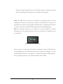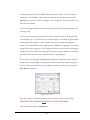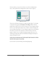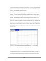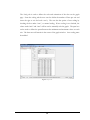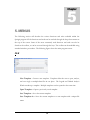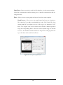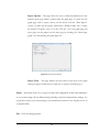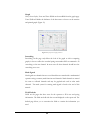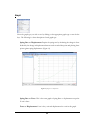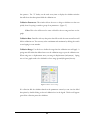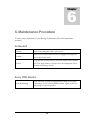
1
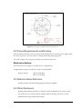
Volume 1 ROEHRIG ENGINEERING, INC. Spring Testing Equipment Add-On Spring Checker / Stand Alone Spring Checker ROEHRIG ENGINEERING, INC. Spring Testing Equipment User Manual Roehrig Engineering, INC. 100 Lexington Parkway Lexington, NC 27292 Phone 336-956-3800 • Fax 336-956-3870 ii Table of Contents 1. IDENTIFICATION AND MACHINE DESCRIPTION .............................. 1 1.1 Dynamometer Identification ...................................................................................... 1 1.2 Manufacturer Identification ...................................................................................... 1 1.3 Normal Operation and Usage .................................................................................... 1 1.4 Incorrect Operation and Usage ................................................................................. 1 2. TECHNICAL DATA ............................................................................... 2 2.1 Machine Weights and Measurements ....................................................................... 2 2.2 Power Requirements and Hookup ............................................................................ 3 Electronics Hookup: ........................................................................................................... 3 2.3 Airborne Noise Emission ............................................................................................ 3 2.4 Other Emissions .......................................................................................................... 3 3. SAFETY................................................................................................. 4 3.1 Personal Protective Equipment ................................................................................. 4 3.2 Product Specific Warnings ........................................................................................ 4 4. GETTING STARTED ............................................................................. 5 4.1 Software Installation and Setup ................................................................................ 5 4.2. Attaching the Spring Checker to the Dyno (AOSC) ............................................... 7 4.3. SASC Setup ................................................................................................................ 8 4.4. Collecting Data ........................................................................................................... 8 4.5 Analyzing Spring Data ............................................................................................. 11 5. MENUS ................................................................................................ 15 FILE .................................................................................................................................. 15 Edit ................................................................................................................................... 18 Display ....................................................................................................................... 19 Test ............................................................................................................................ 19 Units........................................................................................................................... 19 Color .......................................................................................................................... 19 Graph ......................................................................................................................... 20 Smoothing .................................................................................................................. 20 Math Signals ............................................................................................................... 20 Field Defaults ............................................................................................................. 20 Folders / Files ............................................................................................................ 21 Graph ................................................................................................................................ 22 Test ................................................................................................................................... 25 Hardware .......................................................................................................................... 25 View ................................................................................................................................. 26 Window ............................................................................................................................ 27 Settings ............................................................................................................................. 27 Help .................................................................................................................................. 29 6. MAINTENANCE PROCEDURE .......................................................... 30 As Needed ........................................................................................................................ 30 Every TWO Months ....................................................................................................... 30 7. APPENDIX .......................................................................................... 31 7.1 USB to Serial Adapters ............................................................................................ 31 8. WARRANTY AND SERVICE .............................................................. 32 8.1 Warranty ..................................................................................................................... 32 8.2 Technical Support ....................................................................................................... 32 8.3 SERVICE POLICY .................................................................................................... 34 Roehrig Hardware Under Warranty .................................................................................. 34 Roehrig Hardware Not Under Warranty ........................................................................... 34 Factory Repairs ................................................................................................................. 34 Repairs at Customers Facility ........................................................................................... 34 Roehrig Engineering Software Under Warranty............................................................... 35 Roehrig Engineering Software Not Under Warranty ........................................................ 35 Hardware and Software Training ...................................................................................... 35 Purchase Conditions ......................................................................................................... 37 1.0 Payment of Purchase Price ......................................................................................... 37 2.0 Delivery and Transportation ....................................................................................... 37 3.0 Installation and Operator Training .............................................................................. 37 4.0 Warranties and Limitation of Liability ....................................................................... 38 5.0 Design Changes ......................................................................................................... 39 6.0 Non-Disclosure .......................................................................................................... 39 7.0 Entire Agreement / Governing Law / Misc. / Guarantee ........................................... 39 8.0 Definitions ................................................................................................................. 40 9.0 Software License Agreement ...................................................................................... 40 R O E H R I G E N G I N E E R I N G , I N C . Chapter 1 1. Identification and Machine Description 1.1 Dynamometer Identification This manual will cover the following Roehrig Spring Checkers Add-On Spring Checker (AOSC) Stand Alone Spring Checker (SASC) 1.2 Manufacturer Identification Roehrig Engineering Inc. 100 Lexington Parkway Lexington, NC 27295 Phone: +1 336 956-3800 Fax: +1 336 956-3870 1.3 Normal Operation and Usage Roehrig Engineering Spring Checkers are designed to compress springs up to 5,000lbs with a 5,000lb load cell. Any spring medium properly installed with the correct fixture may be tested by a trained operator. The units are designed for continuous usage. 1.4 Incorrect Operation and Usage The spring must be properly installed using the correct fixtures. Only trained operators can correctly and safely use these machines. The dynamometer should only be used if correctly set up and installed by a professional. The machine may not be run if any safeguards have removed, damaged, or tampered with. 1 Chapter 2 2. Technical Data 2.1 Machine Weights and Measurements SASC Weight – 130lbs (59kg) Figure 1: SASC Dimensioned Drawing 2 Figure 1.5: Steel Upper Cup with Bolt Circle for Helical Insert 2.2 Power Requirements and Hookup Add-On Spring Checkers receive power from the dynamometer’s internal power supply; make sure there is power to the dyno prior to starting the Roehrig Spring program. The SASC requires only one power hookup to power the electronics. Electronics Hookup: The electronics power supply is available in two configurations. An appropriate surge-protected power strip is recommended! Spring Checker: 110VAC Wall Plug 220VAC Wall Plug 2.3 Airborne Noise Emission Sound pressure levels from Roehrig Spring Checkers are minimal. 2.4 Other Emissions Roehrig Spring Checkers produce no vibrations which are harmful to the operator, since the operator is not in contact with the machine while it is running. There are no other harmful emissions produced by the machine. 3 Chapter 3 3. Safety 3.1 Personal Protective Equipment Operators should always wear required safety gear for the environment in which they are in. When operating or working near the dynamometer, personnel must always be wearing safety glasses. 3.2 Product Specific Warnings While the spring is being compressed the area between the upper and lower cups will contain numerous pinch points on compression and release. DO NOT attempt to adjust the spring while it is being compressed or released. Keep hands clear. Warning Safety glasses must be worn at all times when operating or working near the damper dynamometer! Warning Only trained operators are permitted to use the damper dynamometer! Caution Always be sure that the spring is installed securely using proper fixtures, and that the crossbar is properly tightened before running a test. 4 Chapter 4 4. Getting Started 4.1 Software Installation and Setup Roehrig Spring Checkers require a PC running Microsoft Windows, XP, or Win 7. The PC must have a minimum of two USB ports for the data cable and software key. NOTE: If you purchased a dynamometer and Add-On Spring Checker together, the Shock and Spring software will be installed at the same time. 1) Make sure the USB Software Key is NOT inserted in the computer and insert the Roehrig Software System Settings/ User Manual thumb drive to begin the software installation. If the software installation wizard will not automatically load, double click on your Removable Disk icon under “My Computer”. Then click 6-442 shock folder, then double click Roehrig Software 6-4-42 application. The setup wizard should now start. 2) Follow the on-screen instructions. When prompted, insert the USB Software Key. If you install the software without the Software Key, the program will only work in Demo Mode. 3) Once setup is complete, reboot your system. 4) Load your system and user settings by opening the Spring software. Then at the top click the tab labeled settings. Go down to System Settings and click Import System Settings. Go to the thumb drive click on the XML file named System Settings and click open. To load your user settings go to Settings, go down to User 5 Settings, and click Import click on the XML file named User Settings and click open. Your calibration documents are now loaded into the program Note: The XML files only need to be installed if the Roehrig software is being installed for the first time on a particular computer. The XML files do not need to be reinstalled if the software is being updated within Shock6. If upgrading from Shock5 (or older) to Shock6, new XML files will be provided by Roehrig Engineering. Note: The Roehrig software may be installed on as many computers as desired allowing users to view and analyze data, however, the software key is required in order to run the dyno. Figure 2: Shock 6 USB Software Key The next step is to connect the data card to the computer. Plug the USB cable into the rectangular port at the PMD and then the other end into the computer. Let the computer find the data card. It should say, "Found new hardware, loading interface", let it go through the process. This loads the software for the PMD. 6 4.2. Attaching the Spring Checker to the Dyno (AOSC) Before attaching the spring checker, make sure the actuator shaft of the dyno is set to its lowest position. (Bottom Dead Center) You will also need to remove the upper and lower clevis’ that are used to hold dampers in place. If your rater is equipped with a hand pump the pump can be quickly clamped to one of the vertical columns on the dyno using the two clamps that are secured to the pump body. The hose end of the pump should face downward. The Catch Bar will fit between the two columns of the dyno and latch on one side with the supplied pin. The base of the Add-On unit will rest on top of the exposed threaded actuator shaft of the dyno. Screw the Upper Cup to the threaded stud on the load cell (where upper clevis was) so that the proper side faces down. The Upper Spring Cup will be made from Aluminum or Steel depending on your specifications. Aluminum Cups have two sides, one for open-ended springs and one for closed-ended springs; Steel Cups will be flat but may contain a bolt circle for the addition of helical adapters. The displacement transducer cable should be plugged into the base of the displacement sensor (to the right of the hydraulic ram) and to the Spring port on the dyno’s electronics board. 7 Figure 3: AOSC with Hand Pump 4.3. SASC Setup The SASC is set up the same as the Add-On rater described earlier. With a Stand Alone unit there should be no need to remove the spring checker from the load frame. Figure 4: SASC 4.4. Collecting Data To start the program, double-click on the Roehrig Spring icon on the desktop. 8 To begin collecting data click on Test from the drop down menus. If you are using an existing test, click on Test. Select your test profile from the pull down list and use the Edit button if you wish to make any changes to the selected test. To create a new test, use the Create Test Wizard. Preload is the range in displacement or force that the spring will be compressed before the test range starts. Test Range is the range the program collects and saves data for the test. The program will save and allow you to view data in the test and preload range. NOTE: the program collects and averages all the samples over the complete test range to calculate the spring rate number. A test with different ranges might produce a difference in spring rate on the same spring if the spring is progressive. All coil springs will show increases in rate as the spring is compressed at some point in the compression. Preload, test range, sample rate, and release speed must all be the same to have repeatable data to compare graphs. If you wish to view the graph with displacement graphed as compression from extended height enter the spring length in the spring size window and click the switch in spring size box. You may save the edited test as the original test name or re-name the test using the Save As button. (Figure 5) . Figure 5: Spring Test Editor Place the spring in on the lower spring cup and lower the cross bar onto the spring. TIGHTEN THE HANDLES AND NUTS ON THE CROSSBAR. Once the crossbar is tight click Start Test. 9 In the next window you may use the zero button to zero the force and displacement sensors. This only affects the live reading and has no effect on the test. (Figure 6) Figure 6: Spring Test Window The next screen will instruct the operator to compress the spring. (Figure 7) As the spring is compressed the bar graphs marked Preload and Test Range will fill in. When the spring has been compressed to the end of the test range a new screen will appear notifying the user to stop compressing the spring, be sure to continue to compress the spring until the screen changes and prompts you to stop. Ending the compression early can disrupt the data collection. At the end of the compression you will be instructed to wait for the program to stabilize, if you over compress the spring the program will warn you. Over compressing the spring will not affect the collected data but loading the load cell past its rating could damage the load cell. THE TOTAL OF PRELOAD AND TEST RANGE FORCE SHOULD NEVER EXCEED THE LOAD CELL RATING. If you are unsure of your load cell rating contact Roehrig Engineering. 10 Figure 7: Spring Test Window After the program stabilizes the user will be prompted to collect data by releasing the compressed spring using the release knob located on the hydraulic pump. A consistent release speed is important to the repeatability of the spring rater because the software is sampling over the release time. Flow control valves are used to regulate the spring release to provide repeatable results. At the end of the release the software will calculate the spring rate using two different methods and display these rates both methods are explained on in the Analyzing Spring Data section of this manual. Click Next to name and save this data collection. After you save the file, the graph will be displayed on the graph screen, Spring Rate will also be displayed next to each file name. From the factory the Spring Rate is displayed as the Average Spring Rate. See Figure 11 to change default settings. 4.5 Analyzing Spring Data When a test is complete the program will display the saved trace of the last collected data file automatically. File names and calculated spring rate are displayed on the left side of the main screen. Multiple data files can be overlaid in the same graph window by checking or un-checking the boxes next to the file name; S is the test range data and P will show the preload data. The color of the selected file trace can be changed by pressing C, or by right-clicking a specific file and selecting change color. Different graphs are available in the Graph pull down menu or on the toolbar. See the Graph 11 section of this manual for a description of each graph. To remove a data file from the template, click the Delete icon in the toolbar; this only closes the file in the program; the file is still saved in the original file location. To aid the operator in analyzing the graph a movable curser and zoom window are available. To use the curser select the desired data file from the list of open files on the left of the screen and use the right and left arrow keys to move the curser along the trace. The data from each data point will be displayed on the status bar at the bottom of the screen. To zoom in on a section of the trace, place your curser at a point on the graph, hold down the left mouse button, and drag a box around the area you wish to zoom, or use the buttons on the zoom tool bar. Use the Reset Zoom button on the tool bar to return to full view. You can copy the graph to a document by clicking the camera icon (Figure 8) in the toolbar, then click paste in the document you have open. Figure 8: Spring Graph viewed as Rate vs. Displacement. The Report tab allows the user to view numeric data from the selected file. (Figure 9) The program will display the data for the file selected on the left side of the screen. 12 The Report Gap box allows the data to be displayed as displacement or force with custom spacing. (Figure 9) The numeric report can be exported to a file or to the clipboard in three different formats under Export. If you are unfamiliar with these formats experiment with each to determine what report will fit your needs. Run Constants tab describes the selected test. The Average Rate is the average of all data points in the test range the Range Rate is a rate average of the first and last data points in the test range. (Figure 8) 13 The Scaling tab is used to define the scale and orientation of the data on the graph page. From the scaling tab the user can also define the number of lines per axis and invert the sign or axis for both x and y. The user has the option of auto scaling by checking the box under “auto”, or manual scaling. If auto scaling is not checked, the values under “min” and “max” will be used to manually scale the graph. The span box can be used to define the spread between the minimum and maximum values on each axis. The data trace will remain in the center of the graph window. Auto scaling must be enabled. Figure 9: Report Tab 14 Chapter 5 5. MENUS The following section will describe the various functions and tasks available within the Spring6 program. All the functions and tasks can be reached through the drop down menus at the top of the screen. Some of the more commonly used functions and tasks can also be found on the toolbar, or can be accessed through hot keys. The toolbar can be modified using standard windows procedures. The following figure shows the main program screen. FILE New Template – Creates a new template. Templates allow the user to open, analyze, and save single or multiple data files in one place. The Legend and Tabbed Analysis Window make up a template. Multiple templates can be opened at the same time. Open Template – Opens a previously saved template. Save Template – Saves the current template. Save Template As – Saves the current template as a new template with a unique file name. 15 Open Data – Opens a previously saved data file and places it in the current template. A data file is created and saved after running a test. A data file contains all the data for a single test only. Print – Allows the user to print graphs and reports from the current template. Graph Layout – Allows user to size graph, legend, and notes on the printout. The “show logo” box adds a user defined logo to the “Title” block. The “logo stretch/shrink fit” box adjusts the size of the logo to fit within the “Title” block. The “Legend” and “Notes” blocks can be moved to different positions using the corresponding sliders. Their sizes can be adjusted using the “Divider at” boxes. The number entered in this box is the percent of the page from the top or left from which each block will start. Figure 5.1: Print Options (Graph Layout) 16 Report Options – This page allows the user to define all parameters for the numeric report page which is printed after the graph page. To print only the graph page with no report, remove all the checks from the “Data Report” section. To print only the reports, uncheck the “Include Graph” box. To print the actual PVP speeds, enter “0” in the “PVP inc.” box. The graph page and report page can be printed on the same page by checking the “Partial page graph” box and adjusting the graph page size. Figure 6.6: Print Options Window Report Fonts – This page defines the font used for each area of the graph and report pages. Double click on each area to open the font dialog box. Export – This button allows you to export your data card configuration (all data card calibrations) or your system settings (all user defined settings including created test and preference settings). It is a good idea to export your system settings to an external device and save it in a safe place in case of a computer failure. Exit – Closes the Spring program. 17 Edit Cut – Used to cut the selected item and place it on the clipboard. Copy – Used to copy the selected item and place it on the clipboard. Paste – Used to paste the item on the clipboard to the selected location. Delete – Used to delete the selected item. Include Preload – Click to display/hide preload in the graph. Snapshot – Takes a “snapshot” (similar to print screen) of the current graph and legend and places it on the clipboard. The “snapshot” can then be paste into any windows program such as Paint, Word, etc. The size of the “snapshot” can be changed in Preferences (F12). Show – Click to display/conceal the highlighted data file. This command is also available as a check box on the legend. File – Allows the user to open and edit the data file properties/description page, also known as “Fields”. Preferences – Opens the preferences window. The majority of the default settings for the program are found here. Keep in mind, many of these settings can be changed in other areas of the program without affecting the default settings. 18 Display To display the preload on all tests click the include the preload button. Default graph will define the graph type that the program will open. The default rate switch will determine the method the program will use to calculate the spring rate displayed in the legend. Test range rate is the most popular method. (Figure 11) Figure 11: Display Settings in Spring Preferences Test The enter Test Description box is used to control when the test description page will be displayed for user to fill in test information. Autofill will use the information entered for the last test for the next test. Settle time is the time that the program will dwell at the end of a test. Units Use this page to set English or Metric measurements in displayed data, Custom option allows the user to mix systems. The CTL-F12 hot key or the unit hotkey can also be used to switch between units. Color This window lets the operator select the colors and order of colors that the program will use for displaying data files graph traces. Click on each box to select the color. 19 Graph Grid, Cursor Styles, Fonts and Trace Width can be modified from the graph page. Trace Width will define the thickness of the data traces as shown on the monitor and printed graph. (Figure 12) Figure 12: Graph options in Spring Preferences Smoothing Smoothing on this page only affects the look of the graph to aid in comparing graphs, it does not affect the recorded spring rate number. REI recommends a 30 smoothing on the rate channel. In most cases all other channels should have the smoothing set to zero. Math Signals Math signals are channels that are not collected but are created with a mathematical operation using constants, math functions and channels. Math channels are treated the same as collected channels and may be graphed and used in other math channels. The math syntax for creating math signals is listed at the end of this manual. Field Defaults Fields are the pages that have areas for the operator to fill in test and spring information. The fields are held with the test and displayed on the report tab. The default page allows you to customize the fields to contain the information you need. 20 Clicking on the edit test Defaults will open the window displayed below. By clicking on a cell you can change the name of a field or the number of lines that will be reserved for that field. By using the INSERT key new lines may be added to expand the field page. To delete a line highlight the name by clicking on it and use the delete key. The default boxes can be used for descriptions that you want to appear with each saved data file as a default. Constants are numbers that would be used with math channels. This window allows the user to completely customize the data displayed on the report page. Click on cell to Highlight. When a cell is highlighted you can modify the contents of that cell. Figure 13: Spring File Field Editor Folders / Files This page allows the user to set the default file names and default directories where the files are saved. 21 Graph Select the graph type you wish to use by clicking on the appropriate graph type or use the hot keys. The following is a short description of each graph type. Spring Rate vs. Displacement: Depicts the spring rate by calculating the change in force divided by the change in displacement between each recorded data point and plotting these points against spring displacement. (Figure 14) Figure 14: Spring Rate vs. Displacement Spring Rate vs. Force: This is the same graph as Spring Rate vs. displacement except the X-axis is force. Force vs. Displacement: Force is the y-axis and displacement the x-axis in this graph. 22 Raw Force vs. Displacement: This graph shows the collected force values compared to displacement without the internal filtering that is built into the program. All other graphs are filtered to eliminate electronic noise that hurts the repeatability of the data. You may view the raw numeric values by clicking the Copy button in the Edit pull down menu with this graph open, then paste to a Microsoft Excel spreadsheet. No numeric data is available on the data page for raw data, to view raw numeric data it must be viewed in Excel. (Figure 16) Figure 16: Raw Force vs. Displacement Validation: With the validation option selected, the program will check the collected data against the validation parameters the operator has entered and return a pass or fail if any data points fall outside the defined area. On a test run after validation is enabled a window will be displayed after the collection is complete informing the operator if the collection passed or failed the validation and what data points were out of range if it failed. Data files that are opened with validation selected will show a green or red box before the file name on the main screen. Validation parameter settings will hold as a default until changed by 23 the operator. The “V” hotkey can be used at any time to display the validation window that will show what data points failed the validation test. Validation Parameters: This window allows the user to design a validation test that can quickly show if a spring is outside a group of set parameters. (Figure 17) Color: This color will be used to create a block for the test range and rate on the graph. Validation Rate: Data files with any data points that fall out side the rates entered here will fail the validation test. The user may select a minimum and maximum by clicking the switch on and typing in a rate number. Validation Range: Use this box to define the range that the validation rates will apply. A spring must fall within the defined rates over the validation range to pass the validation test. When using rate vs displacement enter your range in displacement (inch,mm,m). Spring rate vs force graphs need to be validated in a force range (pounds,kilograms,Newton). Figure 17: Validation Parameter Settings If a collection fails the validation based on the parameters entered you can view the failed data points by double clicking on the red validation box in the legend. This box will appear green if the collection passes the validation. 24 Test Test: This screen is used to perform a spring test as outlined in the Collecting Data section of this manual. Create Test: The create test wizard will walk you through the options to create a new test. After you name the new test the program will save that test in the pull down menu on the test page. Delete Test: Using the delete test button will permanently remove the selected test profile from the from the test profile list. Hardware Data Card: This menu contains specific calibration for each sensor and the data card type. WARNING! ALTERING THESE NUMBERS WILL CHANGE THE CALIBRATION OF YOUR SPRING RATER AND MAKE YOUR DATA INCORRECT. PLEASE CONTACT ROEHRIG ENGINEERING BEFORE MAKING CHANGES! Monitor: This screen shows the live reading for each sensor. Each channel is displayed in graph and numerical form. This window can be used to diagnosis problems with your dyno. 25 View Template List – Displays a list of the currently open templates in a toolbar. Standard Toolbar – Displays the standard Roehrig toolbar, which contains the most commonly used functions. Status Bar – Displays the lower status bar. Toolbars – Lists and displays all other available toolbars. Toolbars may be moved by clicking on the “crosshatching” located on the left side of the toolbar and dragging it to the top, bottom, left, or right side of the program window, or to the center to display it in a new window. The “more options” icon located on the right side of the toolbar can be used to modify the contents of the toolbar. Figure 18: Standard Toolbar Crosshatching More Options Icon 26 Window Window Menu – Allows user to arrange templates within the program using standard Microsoft Windows functions. Also lists currently open templates and currently selected (active) template. Settings User Settings – Exports or Imports user settings. User settings include all settings contained in the “preferences”, including all user tests and math channels. It is recommended that the user export and backup all settings listed under the settings menu on a regular basis in case of a computer crash. System Settings – Exports datacard settings, motor settings, or both. These settings can be used to restore the motor properties and datacard properties (sensor calibration) in case of a computer crash. To import these settings, simply double click on the desired system settings file in any Windows Explorer window. 27 Export all Settings – Exports all user and system settings and saves them as one file. Math Settings – Exports or Imports only the math channels created in “preferences.” Can be used to transfer math channels to other computers running SHOCK6. When importing math channels, the user can choose to replace existing channels with the new channels or merge the existing channels with the new channels. Test Settings - Exports or Imports only the user’s tests. Can be used to transfer tests to other dynos running Shock6. When importing tests, the user can choose to replace existing tests with the new tests or merge the existing tests with the new tests. Test settings cannot be transferred between crank dynos and EMAs (Electro Magnetic Actuators). 28 Help Help Menu – Provides searchable electronic version of this manual, which can also be listed by its table of contents. E-mail support link and interactive trouble shooting manual also provided. The “About” option provides information about the software version, motor, and datacard. 29 Chapter 6 6. Maintenance Procedure To ensure proper performance of your Roehrig Dynamometer follow these maintenance procedures As Needed Columns Keep cleaned and lightly oiled to prevent rust. Crossbar Remove the crossbar handles and nuts (if equipped) and apply antiseize to the crossbar studs. Keep dust and oils away from the electronics board, clean as needed. General DO NOT apply cleaners or solvents to the IR Temperature sensor, chemicals may damage the lens. Every TWO Months Guide Rod Bearing AOSC and SASC models are equipped with a guide rod and guide rod bearing to the left of the hydraulic actuator. Lightly oil the rod and bearing for smooth operation. 30 Chapter 7 7. Appendix 7.1 USB to Serial Adapters In the case where your computer does not come with a Serial port, the use of a USB to Serial Adapter will be required. Roehrig Engineering recommends USB to Serial Adapters from Keyspan for reliability. Model# USA-19HS Figure 19: Keyspan USB to Serial Adapter. Model# USA 19-HS When installing the drivers for the device, follow the manufacturer’s directions. 31 Chapter 8 8. Warranty and Service 8.1 Warranty For one year from the date of delivery (date equipment leaves REI), Roehrig Engineering, Inc. will provide, free of charge, parts and service labor to repair or replace any part of the dynamometer that fails because of a manufacturing defect. This warranty is extended to the original purchaser and any succeeding owner of the product within the one year time period. 8.2 Technical Support Roehrig Engineering, Inc. is committed to providing the best technical support to our customers. If you have any problems using one of our products, please follow these steps before contacting our Technical Support Representative: • Be sure to read the equipment manuals. Many times the answer is right there. • Document the problem you are experiencing. Be as specific as you can. The more information you have, the easier the problem will be to solve. • If you still cannot resolve your problem, have your equipment’s serial number available before calling. 32 Technical Support hours are 8:00AM to 5:00PM Eastern Time, Monday through Friday. E-mail [email protected]. You may also fax in your problems or questions 24 hours a day. Faxes sent outside regular working hours will usually be answered before 10:00AM ET the next working day. Please be sure to use the Customer Service Request Form found later in this document. Include your FAX and phone numbers, and the name of the user. Fax support number (336) 956-3870. Phone support number (336) 956-3800. 33 8.3 SERVICE POLICY Roehrig Hardware Under Warranty A one-year warranty comes with the purchase of new Roehrig Engineering manufactured hardware products. Supplemental service plans are also available at additional cost. The following is a summary of what service can be obtained under the Standard warranty: 1. 2. Factory repairs on hardware product defects; 3. Roehrig Engineering will return the hardware via UPS 2 day air service (USA only). If the customer is outside the continental USA, the customer is responsible for all shipping expenses. Expedited service can be arranged at the customer’s expense; 4. 5. 6. 7. Free technical support, for technical problems and applications, for all trained users; Factory repairs are usually completed within 3 working days of Roehrig Engineering’s receipt of the defective item. The customer is responsible for returning the hardware to Roehrig Engineering; Warranties can be renewed annually on Roehrig Engineering products; A warranty cannot be purchased if the original or renewed warranty has expired. Warranties are transferable to subsequent owners under certain conditions: ✦ ✦ ✦ The equipment is currently under warranty The new owner undergoes training on the equipment A warranty transfer form is completed, and submitted to Customer Service Roehrig Hardware Not Under Warranty • • E-mail is the preferred method to address non-warranty service problems, out of warranty e-mail we be answered at no charge, or the customer may use the Customer Service Request Form for troubleshooting problems via fax at no charge. REI may charge for phone non-warranty problems If the initial trouble shooting does not resolve the problem, then all factory assessments and repairs will follow the following procedure: Factory Repairs 1. 2. 3. 4. The customer sends the part to Roehrig Engineering. The estimated repair cost will be given to the customer prior to the repair. The total cost must be paid prior to beginning of service. System testing, evaluation and repairs can take up to two weeks. However, the part will be scheduled for a service as soon as it arrives at the factory. Roehrig Engineering will return the repaired part via UPS ground service in the USA only. If the customer is outside the continental USA, the customer is responsible for shipping charges. Expedited service can be arranged at the customer’s expense. Repairs at Customers Facility 1. 2. 3. 4. Customer will pay all travel expenses of Roehrig Engineering service personnel. Travel rate is $0.485 per mile, plus $35.00 per hour, maximum $200.00 per day. If it is necessary to fly to the customers location, customer will pay full cost of the airline ticket, plus $35.00 per hour, maximum $200.00 per day travel (not including airline ticket). Customer will pay for all replacement parts plus $100.00 per hour labor. Payment required at time of repair. It may take up to 4 weeks to schedule a service call to the customer’s location. 34 Roehrig Engineering Software Under Warranty • • A one-year warranty comes with the purchase of all new Roehrig Engineering developed software. The warranty includes: 1. Free telephone, e-mail and fax support for all trained users. 2. Free updates and new releases of Roehrig Engineering developed software. Roehrig Engineering Software Not Under Warranty • Once the warranty has lapsed on Roehrig Engineering software, the following applies: 1. REI may charge for telephone support at standard service rates; 2. Questions may be faxes or e-mailed to Roehrig Engineering’s customer service department at no charge. Please use the attached form for fax request. Hardware and Software Training Roehrig Engineering’s training program is designed to instruct trainees in the operation of the equipment that the customer has purchase. The training sessions are set up for each trainee to obtain valuable hands on application exposure. This will help the trainees in their everyday use of the equipment. Training for additional personnel, and advanced training is available at additional expense. 35 ROEHRIG INC. 100 Lexington Parkway Lexington NC 27295 336 956 3800 Transfer of Warranty Service Plan Agreement __________________________________(Seller’s Name) hereby waives all rights under warranty service policy for: Dynamometer Serial Number:______________ Purchased originally on:___________________(date). ___________________________________(Buyer’s Name) hereby assumes all rights and obligations of the Hardware and/or Software Warranty Service Policy from: _________________________(Date of Transfer). This transfer is valid only under the following conditions. 1. 2. 3. The Dynamometer is currently under warranty New owner undergoes training from Roehrig Engineering This warranty transfer form is completed, and submitted to Customer Service. AGREED ________________________________ (Print Seller’s Corporate Name) _____________________________ (Print Buyer’s Corporate Name) By X____________________________ By X_________________________ ____________________________ (Print Name of Signatory) _________________________ (Print Name of Signatory) Roehrig Engineering, Inc. Approved by X_____________________________ ____________________________ 36 ENGINEERING Purchase Conditions All Purchase Orders (hereafter, the “Order”) for Roehrig Engineering provided products and services (hereafter, the “Product”) are subject to the following terms and conditions, which are agreed to by the Purchaser. 1.0 Payment of Purchase Price 1.1 Purchaser hereby promises to pay to the order of Roehrig Engineering all deferred portions of the Purchase Price, together with the interest on late purchase price payments payable at 1.5% per month (18% per annum). 1.2 the Purchaser grants to Roehrig Engineering a security interest in the products sold pursuant to the Order, which may be perfected by UCC-1 Financing Statements to be recorded in the applicable County of the Purchaser’s business location and filed with the Secretary of State’s Office, which security interests will remain in effect until payment in full of the purchase price together with the interest on late purchase price payments payable thereon had been received by Roehrig Engineering. 1.3 If the Purchaser fails to make full payment of the purchase price within the period set out in the Order, Roehrig Engineering shall have the following remedies, which shall be cumulative and not alternative: A. the right to cancel the Order and enter the Purchaser’s premises to re-take possession of the Product, in which event the Purchaser agrees that any down-payment or deposit shall be forfeited to Roehrig Engineering, as liquidated damages and not as a penalty, and all costs incurred shall be payable by the Purchaser upon written demand. B. the right to enter the Purchaser’s premises and remove any Software, components of the Product or other items necessary in order to render the Product inoperative. C. the right to withhold all services which would otherwise be required to be provided by Roehrig Engineering pursuant to the Warranties set out in Section 5 hereof. D. terminate any existing software license agreement E. pursue any other available remedy, including suing to collect any remaining balance of the purchase price. No waiver by Roehrig Engineering of its rights under these conditions shall be deemed to constitute a waiver of subsequent breaches or defaults by the Purchaser. In the event more than one Product is being purchased pursuant to the Order, unless otherwise set forth herein, each payment received by Roehrig Engineering from Purchaser shall be applied pro rata against the cost of each product rather than being applied to the purchase price of any product. 2.0 Delivery and Transportation 2.1 2.2 2.3 Delivery dates are estimates and not guarantees, and are based upon conditions at the time such estimate is given. Roehrig Engineering shall not be liable for any loss of damage, whether direct, indirect or consequential, resulting from late delivery of the product. The Purchaser’s sole remedy if the Product is not delivered within 90 days of the estimated delivery date, shall be to cancel the Order and recover from Roehrig Engineering without interest or penalty, the amount of the down-payment or deposit and any other part of the purchase price which has been paid by the Purchaser. Notwithstanding the foregoing, such right of cancellation shall not extend to situations where late delivery is occasioned by causes beyond Roehrig Engineering’s control, including, without limitation, compliance with any rules, regulations, orders or instructions of any federal, state, county, municipal or other government or any department or agency thereof, force majuere, acts or omissions of the Purchaser, acts of civil or military authorities, embargoes, war or insurrection, labor interruption through strike or walkout, transportation delays and other inability resulting from causes beyond Roehrig Engineering’s control to obtain necessary labor, manufacturing facilities or materials from its usual sources. Any delays resulting from such causes shall extend estimated delivery dates by the length of such delay. Responsibility for all costs and risks in any way connected with the storage, transportation and installation of the Product shall be borne entirely by the Purchaser. If any disagreement arises as to whether or not damage to the Product was in fact caused in storage, transit or installation, the opinion of Roehrig Engineering’s technical advisers, acting reasonably, shall be conclusive. 3.0 Installation and Operator Training 3.1 The Purchaser shall be responsible for installation of the Product, including, without limitation, the preparation of its premises, the uncrating of the product and setting up of the Product for operation. Purchaser may elect to order contract services from Roehrig Engineering to perform this service should they elect to do so. 37 4.0 Warranties and Limitation of Liability 4.1 Roehrig Engineering warrants that (subject to Section 4.6), the Product shall be free from defects in workmanship or material affecting the fitness of the product for its usual purpose under normal conditions of use, service and maintenance. 4.2 Roehrig Engineering warrants that the software shall operate according to specifications and the system shall operate and perform in the manner contemplated in connection with the usual purpose for which it was designed. 4.3 The warranties set out in paragraphs 4.1 and 4.2 above (together called the “Warranties”) shall expire at the end of the twelve (12) month period commencing on the first day of the first month after the date of shipment from the Roehrig Engineering factory (the “Warranty Period”). 4.4 Subject to the limitations contained in Section 4.6, the Warranties shall apply to any defects found by the Purchaser in the operation of the Dynamometer or the software and is reported to Roehrig Engineering within the Warranty Period. If the Dynamometer or the software is found by Roehrig Engineering, acting reasonably, to be defective, and if the defect is acknowledged by Roehrig Engineering to be the result of Roehrig Engineering’s faulty material or workmanship, the Dynamometer or Software will be repaired or adjusted to the extent found by Roehrig Engineering to be necessary, or at the option of Roehrig Engineering, replaced with a new Dynamometer, Software, or parts thereof at no cost to the purchaser. Claims under the Warranties shall be made by delivering written notice to Roehrig Engineering of the defect in the System, Dynamometer, or the Software. Within a reasonable time of receipt of such service personnel and warranty service will be provided at no cost to the Purchaser. If in the reasonable opinion of Roehrig Engineering the dynamometer and Software are not defective, the Purchaser shall pay the cost of service, which shall be the amount that Roehrig Engineering would otherwise charge for that service and shall include, without limitation, shipping, handling, and an hourly service charge. 4.5 The Warranties do no apply to A. any defects in any component of a System where, if in the reasonable opinion of Roehrig Engineering, the Dynamometer, Software or System has been improperly stored, installed, operated, or maintained, or if Purchaser has permitted unauthorized modifications, additions, adjustments and/or repair to any part of the System, or which might affect the System, or defects caused or repairs required as a result of causes external to Roehrig Engineering workmanship or the materials used by Roehrig Engineering. As used herein, “unauthorized” means that which has not been approved and permitted by Roehrig Engineering. B. C. D. The Warranties shall not cover replacement of expendable items including, but not limited to, fuses, diskettes, printer paper, printer ink, printing heads, disk cleaning materials, wear plates, or similar items. The Warranties shall not cover minor preventative and corrective maintenance. Any equipment or its components which was sold or transferred to any party other than the original Purchaser without the expressed written consent of Roehrig Engineering. 4.7 Factory Repairs A. IF SYSTEM IS UNDER WARRANTY: The Purchaser agrees to ship the Product to Roehrig Engineering in the original packing containers. Roehrig Engineering will return the repaired or replaced Product. Roehrig Engineering will incur the expense of the needed part and all return shipping charges to the Purchaser. Roehrig Engineering may authorize of a component of the Product to perform the service. B. IF SYSTEM IS NOT UNDER WARRANTY: The Purchaser is responsible for the cost of the replacement part or software, and all shipping charges. 4.8 Nothing herein contained shall be construed as obligating Roehrig Engineering to make service, parts, or repairs for any product available after the expiration of the Warranty Period. Limitation of Liability 4.9 Roehrig Engineering shall not be responsible under any circumstances for special, incidental or consequential damages, including, but not limited to, injury or death of any operator or other person, damage or loss resulting from inability to use the System, increased operating costs, loss of production, loss of anticipated profits, damage to property, or other special, incidental, or consequential damages of any nature arising from any cause whatsoever whether based in contract, tort (including negligence), or any other theory of law. Roehrig Engineering’s only liability hereunder, arising from any cause whatsoever, whether based in contract, tort (including negligence) or any other theory of law, consists of the obligation to repair or replace defective components in the System or Dynamometer subject to the limitations set out above in this section. This disclaimer of liability for consequential damage extends to any such special, incidental or consequential damages which may be suffered by third parties, either caused directly or indirectly resulting from test results or data produced by the system or any component thereof and the Purchaser agrees to indemnify and save Roehrig Engineering harmless from any such claims made by third parties. 4.10 The foregoing shall be Roehrig Engineering’s sole and exclusive liability and the Purchaser’s sole and exclusive remedy with respect to the system. THE SOLE RESPONSIBILITY OF ROEHRIG ENGINEERING UNDER THE WARRANTIES IS STATED HEREIN AND ROEHRIG ENGINEERING SHALL NOT BE LIABLE FOR CONSEQUENTIAL, INDIRECT, OR INCIDENTAL DAMAGES, WHETHER THE CLAIM IS FOR BREACH OF WARRANTY, NEGLIGENCE, OR OTHERWISE. OTHER THAN THE EXPRESS WARRANTIES HEREIN STATED, ROEHRIG ENGINEERING DISCLAIMS ALL WARRANTIES INCLUDING IMPLIED WARRANTIES OF MERCHANTABILITY AND FITNESS. Roehrig Engineering does not authorize any person (whether natural or corporate) to assume for Roehrig Engineering any liability in connection with or with respect to the Products. No agent or employee of Roehrig Engineering has any authority to make any representation 38 or promise on behalf of Roehrig Engineering, except as expressly set forth herein, or to modify the terms or limitations of the Warranties. Verbal statements are not binding by Roehrig Engineering. 4.11 The Warranties extend only to the Purchaser and are transferable, only under the following conditions: A. The Dynamometer is currently under warranty. B. New owner undergoes training. C. A Roehrig Engineering warranty transfer is completed, and submitted to customer service. All claims under the Warranties must originate with the Purchaser, or any subsequent owner, and the Purchaser will indemnify and save Roehrig Engineering harmless from any claims for breach of warranty asserted against Roehrig Engineering by any third party. 4.13 Oral representations of Roehrig Engineering or its sales representatives, officers, employees or agents cannot be relied upon as correctly stating the representations of Roehrig Engineering in connection with the system. Refer to this purchase order, any exhibits hereto and any written materials supplied by Roehrig Engineering for correct representations. 4.14 PURCHASER ACKNOWLEDGES THAT IT HAS PURCHASED THE SYSTEM BASED UPON ITS OWN KNOWLEDGE OF THE USES TO WHICH THE SYSTEM WILL BE PUT. ROEHRIG ENGINEERING SPECIFICALLY DISCLAIMS ANY WARRANTY OR LIABILITY RELATED TO THE FITNESS OF THE SYSTEM FOR ANY PARTICULAR PURPOSE OR ARISING FROM THE INABILITY OF THE PURCHASER TO USE THE SYSTEM FOR ANY PARTICULAR PURPOSE. 5.0 Design Changes 5.1 The Dynamometer, the Software, and the System are subject to changes in design, manufacture and programming between the date of order and the actual delivery date. Roehrig Engineering reserves the right to implement such changes without the Purchaser’s consent; however, nothing contained herein shall be construed as obligating Roehrig Engineering to include such changes in the Dynamometer, Software, or System provided to the Purchaser. 6.0 Non-Disclosure 6.1 All Software including, without limitation, any Roehrig Engineering special user programs, provided to the Purchaser as part of the system, either at the time of or subsequent to the delivery of the Dynamometer, is the intellectual property of Roehrig Engineering. The Purchaser shall not reproduce or duplicate, disassemble, decompile, reverse engineer, sell, transfer or assign, in any manner the Software or permit access to or use thereof by any third party. The Purchaser shall forthwith execute any further assurances in the form of non-disclosure or licensing agreements which may reasonably be required by Roehrig Engineering in connection with the software. 7.0 Entire Agreement / Governing Law / Misc. / Guarantee 7.1 7.2 7.3 7.4 7.5 These Purchase conditions constitute the entire agreement between Roehrig Engineering and the Purchaser in respect to the Product. There are no representations or warranties by Roehrig Engineering, express or implied, except for those herein contained and these conditions supersede and replace any prior agreements between Roehrig Engineering and the Purchaser. No representative of Roehrig Engineering has any authority to modify, alter, delete or add to any of the terms or conditions hereof. Any such modifications shall be absolutely void unless made by instrument in writing properly executed by an actual authorized employee or agent of Roehrig Engineering. The terms and conditions hereof shall be binding upon Roehrig Engineering and the Purchaser, and shall not be construed in accordance with the laws of the State of North Carolina, United States of America. Roehrig Engineering shall be entitled to recover all of its reasonable fees and costs including, but not limited to, its reasonable attorney’s fees incurred by Roehrig Engineering in connection with any dispute or litigation arising thereunder or in connection herewith, including appeals and bankruptcy or creditor reorganization proceeds. These conditions shall not be construed more strictly against one party that another as a result of one party having drafted said instrument. 39 8.0 Definitions 8.1 8.2 8.3 8.4 8.5 8.6 8.7 “Roehrig Engineering” means Roehrig Engineering, Inc. “Purchaser” means the party buying the Product who is legally obligated hereunder. “Software” means all computer programs, including diskettes containing such computer programs sold pursuant to the Order. “Product” means the Dynamometer, the Software, operating manuals and any other product or merchandise sold pursuant to the Order. “System” means a combination of the Dynamometer, the Software, the Computer, and optional parts associated with the Dynamometer. “Purchase Order” means the original document issued from the Purchaser to Roehrig Engineering, listing all parts and/or services to be purchased and the agreed purchase price. “Warranty Transfer Form” means a document to be completed for the transfer of the Roehrig Engineering Warranty. This document is available from Roehrig Engineering upon request. 9.0 Software License Agreement The Software License Agreement is part of the Operating Manual for the product and software System that you have purchase from Roehrig Engineering, Inc. (collectively, the “Licenser”). By your use of the software you are agreeing to the terms and conditions of this Software License Agreement. Throughout this Software License Agreement, the term “Licensee” means the owner of the System. 9.1 The Licenser hereby grants the Licensee the non exclusive right to use the computer software described in this Operating Manual (the “Software”). The Licensee may sell the software key but may not assign, sub-license, rent or lease the Software to any third party without the Licenser’s prior written consent. 9.2 The Licenser further grants the Licensee the right to make a backup copies of the Software media and use the software in demo mode. The Licensee agrees that it will not decompile, disassemble, reverse engineer, copy, transfer, or otherwise use the Software except as permitted by this section. 9.3 The Licensee is licensed to use the Software only in the manner described in the Operating Manual. Use of the Software in a manner other than that described in the Operating Manual or use of the Software in conjunction with any non-Licenser product which decompiles or recompiles the Software or in any other way modifies the structure, sequence or function of the Software code, is not an authorized use, and further, such use voids the Licenser’s Warranty as set forth below. 9.4 The only warranty with respect to the Software and the accompanying written materials is the warranty, if any, set forth in the Quotation/Purchase Order and Service Policy pursuant to which the Software was purchased from the Licenser. 9.5 THIS WARRANTY IS IN LIEU OF OTHER WARRANTIES, EXPRESS OR IMPLIED, INCLUDING, BUT NOT LIMITED TO, THE IMPLIED WARRANTIES OF MERCHANTABILITY AND FITNESS FOR A PARTICLUAR PURPOSE WITH RESPECT TO THE SOFTWARE AND WRITTEN MATERIALS. IN NO EVENT WILL THE LICENSER BE LIABLE FOR DAMAGES, INCLUDING ANY LOST PROFITS RO OTHER INCIDENTAL OR CONSEQUENTIAL DAMAGES ARISING OUT OF THE USE OR INABILITY TO USE THE SOFTWARE, NOTWITHSTANDING THAT THE LICNESER MAY HAVE BEEN ADVISED OF THE POSSIBILITY OF SUCH DAMAGES, THE LICENSER WILL NOT BE LIABLE FOR ANY SUCH CLAIM BY ANY OTHER PARTY. In the event of any breach by the Licensee of this Agreement, the license granted hereby shall immediately terminate and the Licensee shall return the Software media and all written materials, together with any copy of such media or materials, and the Licensee shall keep no copies of such items. The interpretation of this Agreement shall be governed by the following provisions: A. This agreement shall be construed pursuant to and governed by the substantive laws of the State of North Carolina (and any provision of North Carolina laws shall not apply if the law of a state or jurisdiction other than North Carolina would otherwise apply). B. If any provision of this Agreement is determined by a court of competent jurisdiction to be void and non-enforceable, such determination shall not affect any other provision of this Agreement, and the remaining provisions of this Agreement shall remain in full force and effect. If any provision or term of this Agreement is susceptible to two or more constructions or interpretations, one or more of which would render the provision or term void or non-enforceable, the parties agree that a construction or interpretation which renders the term of provision valid shall be favored. C. This Agreement constitutes the entire Agreement, and supersedes all prior agreements and understandings, oral and written, among the parties to this Agreement with respect to the subject matter hereof. 9.8 If a party engages the service of an attorney or any other third party or in any way initiates legal action to enforce its rights under this Agreement, the prevailing party shall be entitled to recover all reasonable costs and expenses (including reasonable attorney’s fees before trial and in appellate proceedin 40