1
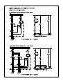
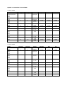
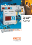
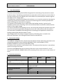
The direct current braking block
DCBB 16, DCBB 63, DCBB 80
1.
USER MANUAL
Use, characteristic
The direct current braking block DCBB is designated for the braking of asynchronous motors
by direct current. The braking is performed in to two phases of the motor by a current from a
one way rectifier with a zero diode, both of the diodes are protected by RC members against
the effects of the voltage spikes.
The DCBB when connected according to the enclosure, or in a similar connection securing the
maintaining of technical parameters, ensures the shortening of the rundown period of the
motors following the instruction for stopping.
The amount of the braking current, which means the braking intensity, is given by the
impedance of the motor’s winding, and it can be affected by the connection method and the
amount of the supply voltage.
The time of the effect of the braking current is set during the putting into operation by a time
relay, for the necessary period for putting the motor into a calm state, so that the motor is
not unnecessarily loaded by the braking current. According to the application method, the
braking period ranges between about 2 to 10s.
Special applications, for example a higher frequency of breaking than is stated in the
technical information, has to be agreed upon with the manufacturer.
2. Construction design
The DCBB 16 is designed to be mounted into distribution boards while being attached to the
normalized installation strips of profiles EN 50035 ( TS 32 ) and EN 50022 ( TS 35 ).
DCBB 63, DCBB 80 only for the strip EN 50022 (TS35)
The brake circuits are built in to the plastic cover. The removal of the heat loss is secured by a
cooler on the top of the cover.
The terminals DCBB16 allow the connecting of one wire up to a cross-section of 2.5 mm 2 .
The terminals DCBB 63, DCBB 80 allow the connecting of one wire up to a cross-section of
6mm 2 .
3. Technical parameters
Type
Operational voltage
Average value of the braking DC
current
Period and frequency of braking
Operational environment
Operational temperature
Protection
Dimensions
Weight
11/2011
DCBB16
max. 400V AC
max. 16A
DCBB63
max. 500V AC
max. 63A
DCBB80
max. 500V AC
max. 80A
about 2 ÷ 10 s, max 30 cycles / hour
ambient temperature –10 to +50 °C, relevant
humidity max. 80%
arbitrary
IP20
79 x 96 x 81 mm 110 x 110 x 123 mm
0.35 kg
0.86 kg
page: 1
pages: 2
The direct current braking block
DCBB 16, DCBB 63, DCBB 80
4.
USER MANUAL
Related norms
ČSN EN 60146-1-1 „Semiconductor converters - general requirements for converters with
network commutation“
ČSN EN 60204-1 „Machine equipment safety - Electrical devices of machines“
5.
Installation, operation and maintenance
The installation of the DCBB must correspond to the valid norms and regulations, primarily it
has to correspond to the norm ČSN 60204-1.
The evaluation of the concordance of the device, before being introduced to the market or in
to operation for the entire system, including the DCBB and the method of its electrical
installation, is the responsibility of the customer of the product.
The product does not contain high-frequency circuits – sources of interference and due to the
reason of its utilization in a machine’s electrical installation, it is not necessary to perform any
further verification of concordance with regards to the EMC.
The DCBB do not require any special operation or maintenance.
6.
Packing, transportation and storage
The DCBB are delivered packed in a carton box.
The transportation of the DCBB is done by regular transportation means. During
transportation, the DCBB must be secured in such a way, so that they do not get damaged.
It is possible to store the DCBB in areas protected against undesired effects, with an ambient
temperature of –10 to +50ºC with a relative humidity of max. 80%.
7.
Disposal
During the operation or the disposal of the device, it is necessary to maintain the relevant
national regulations about the environment and the disposal of waste. In the case that the
device has to be scrapped, it is necessary during its scrapping to proceed according to
separated disposal, which means to respect the difference of materials and their composition
(for example metals, plastics, etc.)
During separated disposal, it is necessary to refer to specialized companies, who perform the
collection of these materials and at the same time respect the valid local norms and
regulations.
Enclosure no. 1 - Examples of application of the DCBB16, 63, 80 in vibrating technology
Enclosure no. 2 - Table of values for 1 motor
Enclosure no. 3 - Table of values for a pair of motors
Processed by: Pavel Pech
11/2011
page: 2
pages: 2
Apendix 2 – Instructions for use of DCBB
1 motor 3x400V
M1
FO12/6
NO02-515,805,1090
NO12
NO16
NO14
NO28
NO22
NO26
NO38
NO24
NO36
NO32
NO34
NA36
FU1 [A gG]
2
FU2 [A gG]
4
FA1
LRD03
0,25-0,40A
KM1
LC1D09
KM2
LC1D09
GU1
BSB16
2
4
LC1D09
LC1D09
BSB16
4
6
LRD04
0,40-0,63A
LRD05
0,63-1A
LC1D09
LC1D09
BSB16
4
8
LC1D09
LC1D09
BSB16
6
8
LC1D09
LC1D09
BSB16
10
10
LC1D09
LC1D12
BSB16
NA32
NA34
NA44
NA46
NA54
NA56
NA64
16
16
LRD06
1-1,7A
LRD07
1,6-2,5A
LRD08
2,5-4A
LRD10
4-6A
LC1D09
LC1D18
BSB63
20
25
LC1D09
LC1D18
BSB63
20
40
LC1D12
LC1D32
BSB80
NA66
25
40
LRD12
5,5-8A
LRD14
7-10A
LRD16
9-13A
LC1D18
LC1D40
BSB80
FU1 [A gG]
2
FU2 [A gG]
4
KM1
LC1D09
KM2
LC1D09
GU1
BSB63
2
4
FA1
LRD02
0,16-0,25A
LRD03
0,25-0,40A
LC1D09
LC1D09
BSB63
4
6
LRD05
0,63-1A
LC1D09
LC1D12
BSB63
4
8
LRD06
1-1,7A
LC1D09
LC1D12
BSB63
6
8
LC1D09
LC1D18
BSB63
10
10
LC1D09
LC1D18
BSB63
16
16
LRD07
1,6-2,5A
LRD08
2,5-4A
LRD10
4-6A
LC1D09
LC1D32
BSB63
20
40
LC1D12
LC1D40
BSB80
25
40
LRD14
7-10A
LRD16
9-13A
LC1D18
LC1D50
BSB80
1 motor 3x500V
M1
NO02-515,805,1090
NO16
FO12/6
NO12
NO14
NO28
FO22/6
NO22
NO24
NO26
NO32
NO34
NO36
NA36
NO34
NA32
NA34
NA44
NA46
NA54
NA56
NA64
NA66
Apendix 3 – Instructions for use of DCBB
2 motors 3x400V
M1,M2
FO12/6
NO02-515,805,1090
NO12
NO16
NO14
NO28
NO22
NO26
NO38
NO24
NO36
NO32
NO34
NA36
FU1 [A gG]
4
FU2 [A gG]
4
FA1,FA2
LRD03
0,25-0,40A
KM1,KM2
LC1D09
KM3
LC1D09
GU1
BSB16
4
4
LC1D09
LC1D09
BSB16
4
4
LRD04
0,40-0,63A
LRD05
0,63-1A
LC1D09
LC1D09
BSB16
6
6
LC1D09
LC1D09
BSB16
8
8
LC1D09
LC1D09
BSB16
12
10
LC1D09
LC1D12
BSB16
NA32
NA34
NA44
NA46
NA54
NA56
NA64
20
12
LRD06
1-1,7A
LRD07
1,6-2,5A
LRD08
2,5-4A
LRD10
4-6A
LC1D09
LC1D18
BSB63
25
12
LC1D09
LC1D18
BSB63
32
20
LC1D12
LC1D25
BSB63
NA66
32
20
LRD12
5,5-8A
LRD14
7-10A
LRD16
9-13A
LC1D18
LC1D25
BSB63
FU1 [A gG]
2
FU2 [A gG]
4
KM1,KM2
LC1D09
KM2
LC1D09
GU1
BSB63
4
4
FA1,FA2
LRD02
0,16-0,25A
LRD03
0,25-0,40A
LC1D09
LC1D09
BSB63
4
4
LRD05
0,63-1A
LC1D09
LC1D09
BSB63
6
8
LRD06
1-1,7A
LC1D09
LC1D12
BSB63
8
8
LC1D09
LC1D18
BSB63
12
10
LC1D09
LC1D18
BSB63
20
16
LRD07
1,6-2,5A
LRD08
2,5-4A
LRD10
4-6A
LC1D09
LC1D25
BSB63
32
20
LC1D12
LC1D40
BSB63
32
20
LRD14
7-10A
LRD16
9-13A
LC1D18
LC1D40
BSB63
2 motors 3x500V
M1,M2
NO02-515,805,1090
NO16
FO12/6
NO12
NO14
NO28
FO22/6
NO22
NO24
NO26
NO32
NO34
NO36
NA36
NO34
NA32
NA34
NA44
NA46
NA54
NA56
NA64
NA66