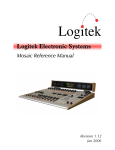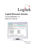
1
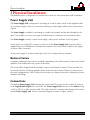
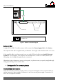
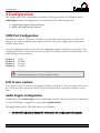
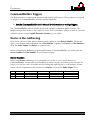
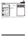
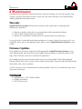
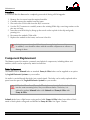
Logitek Electronic Systems Remora Reference Manual Revision 2.0 Aug 2009 Logitek Electronic Systems, Inc. 5622 Edgemoor Drive Houston, Texas 77081 USA Tel Fax +1-713-664-4470 +1-713-664-4479 Email [email protected] Web www.logitekaudio.com Contents © 2009 Logitek Electronic Systems, Inc Notice Every effort has been made to supply complete and accurate information. However, Logitek Electronic Systems, Inc. assumes no responsibility for its use, nor any infringement of patents or other rights of third parties, which would result. Worldwide rights reserved. Except for your own personal use, no part of this publication may be stored in a retrieval system, transmitted or reproduced in any way, including but not limited to photocopy, photograph, magnetic or other record, without the prior agreement and written permission of Logitek Electronic Systems, Inc. Logitek is a trademark of Logitek Electronic Systems, Inc. All other trademarks acknowledged. All specifications are subject to change without notice. Logitek Remora Reference Manual 1 Introduction Document Revisions Date August 2009 2 Revision 2.0 Author Ben Hietbrink Notes Second release of Remora reference manual Logitek Remora Reference Manual 1 Introduction Contents 1 Introduction ......................................................................................................................... 4 About this Manual ............................................................................................................. 4 About Remora ................................................................................................................... 5 System Requirements ........................................................................................................ 6 2 Unpacking ............................................................................................................................ 8 Parts List ........................................................................................................................... 8 Unpacking ........................................................................................................................ 8 3 Physical Installation ............................................................................................................. 9 Power Supply Unit ............................................................................................................ 9 Remora Frames ................................................................................................................. 9 Connections ...................................................................................................................... 9 4 Configuration...................................................................................................................... 12 COM Port Configuration.................................................................................................. 12 LCD Screen contrast ........................................................................................................ 12 Audio Engine Configuration ............................................................................................. 12 CommandBuilder Triggers ............................................................................................... 13 Device & Bus Addressing ................................................................................................. 13 5 Operation ........................................................................................................................... 15 Remora Module .............................................................................................................. 15 6 Maintenance ....................................................................................................................... 21 Warranty ........................................................................................................................ 21 Firmware Updates ........................................................................................................... 21 Component Replacement ................................................................................................ 22 Appendix A Release Notes ..................................................................................................... 25 Release Notes ................................................................................................................. 25 Known Issues .................................................................................................................. 25 Appendix B Specifications ..................................................................................................... 26 Remora Frames ............................................................................................................... 26 Remora Modules ............................................................................................................. 27 Remora Power Supply ..................................................................................................... 27 Appendix C Pinouts................................................................................................................ 28 To Audio Engine.............................................................................................................. 28 GPIs................................................................................................................................ 28 To Surface ...................................................................................................................... 29 Appendix D Spares Kit ........................................................................................................... 30 Contents ......................................................................................................................... 30 Logitek Remora Reference Manual 3 Introduction 1 Introduction About this Manual This manual describes the installation and operation of the Logitek Remora control surface. Intended Audience This manual is aimed at Engineers and Technical Operators responsible for installing, configuring and supporting a Logitek Console Router System with the Remora surface. In the context of a system installation, or to become familiar with the entire Logitek Console Router System, the reader should also reference: Audio Engine Installation & Operation Manual AEConfig User’s Manual Supervisor User’s Manual CommandBuilder Manual The content of this manual relevant to console operators (Chapter 5) is also duplicated in the separate Remora Operators Manual. This provides announcers with a brief overview of using the surface in a broadcast environment. Manual Conventions The following conventions are used in this manual: This text indicates a menu choice to be made, with an arrow separating a multi-level selection, eg Control Panel Users & Passwords. This can be a menu choice in a Logitek application, or within Windows. Indicates a “see-also” section in this manual, or another Logitek manual. The exclamation symbol signifies an important note or critical information. This text represents a command, script block example, instruction to be typed, or directory path. TIP: 4 A useful tip from our knowledge base! Logitek Remora Reference Manual 1 Introduction About Remora First released in 2002, Remora was designed to replace the ROC series of consoles, and adds many new features, including softkey buttons, and single-button access to more functions. The Remora surface is based on a series of modules that can be configured to suit the user’s requirements. These modules include: REM-4 REM-6 REM-24B 4 Fader Module (control module) 6 Fader Module (expansion module) 24 Button Softkey Module (expansion module) The main frame is available in a number of different sizes to accommodate a variety of console sizes and fader numbers; 4, 10, 16 and 22. The frame is designed to be placed on a desk for semi permanent installation. Logitek Remora Reference Manual 5 Introduction System Requirements Remora is designed to connect to a Logitek Audio Engine running DSP version 3.x or later. Certain Remora functions may require a specific type or release of DSP card. Contact Logitek Electronic Systems or your reseller if you are unsure, or are adding a Remora surface to a pre-existing Logitek facility. System Architecture Put simply, the Remora surface is just a remote control panel for the Audio Engine. Unlike traditional analog consoles, no audio passes through the Remora or its faders (with the exception of the cue speaker audio). The Remora talks to the Audio Engine using the Logitek Command Protocol, with all audio processing occurring inside the Audio Engine. The mixing, routing and processing of audio is not dependent upon PCs. However, additional functionality, such as macro buttons, scene snapshots, intercoms, delay control and software tools interface to the system using the Supervisor PC application. Whilst Supervisor is not a requirement to run a Logitek Console Router System, most systems are now sold with this PC suite, as it unlocks the true power of the Logitek system. The Remora surface contains many programmable buttons, which require scripting using CommandBuilder. The functionality for these buttons is then executed by Supervisor. If these buttons are performing on-air critical functions, such as delay control or studio switching, running a Dual Supervisor configuration is highly recommended. Surfaces are remote control panels for Audio Engine Surfaces Audio Engines process Audio and GPI control events Audio Engines Console Surfaces AE1 Control Panels Supervisor executes scripts and provides gateway to IP world Supervisor PCs Client PCs Software vTools Supervisor PC Main Software vTools Software vTools Fibre Audio Network Console Surfaces Control Panels Serial Comms AE2 Client PCs interact with Audio Engines via Supervisor Software vTools Supervisor PC Backup (optional) Serial Comms Software vTools Software vTools TCP/IP Serial TCP/IP Fibre Figure 1 - Logitek System Architecture 6 Logitek Remora Reference Manual 1 Introduction Compatibility Matrix The Remora is designed for use with all Logitek Audio Engines. The Remora retains compatibility with other surfaces for the majority of its features. Support for Remora specific additional features has been progressively added to other components of the system. Remora v3.x firmware was released in November 2005. Following is the minimum software release version/date that is required for Remora support. Component AE-C2 Controller Card AE-C6 Controller Card SharcAttack DSP General Support v3.x v3.x v3.x LoneSharc DSP Supervisor CommandBuilder AEConfig v3.x 2002 / v3 2002 2002 Additional Features v3.25 Nov 2005 for extra cue/aux meters v3.63 Nov 2005 for extra cue/aux meters v3.60 Jun 2005 or later v3.63 Nov 2005 for extra cue/aux meters Contact Logitek or your reseller v3.0 November 2005 v3.0 November 2005 v3.0 for 16 character See Appendix A for Remora related release notes and version information. Logitek Remora Reference Manual 7 Unpacking 2 Unpacking This section details what you should do when unpacking your newly arrived Remora surface. Parts List The exact list of parts received will vary depending on your order, but should generally include: 1 x Remora Power Supply 1 x fully assembled Remora frame, containing modules as ordered 1 x SCSI (or DB-15 in older systems) type connecting cable (surface to power supply) You will receive a parts list with the system that is specific to the modules on your order. Unpacking Carefully unpack the cartons whilst looking for any signs of shipping damage. You may wish to save the shipping cartons until the operation of the system is verified. Report any damage to the shipping carrier immediately. Verify that the contents of each box match the packing list and report any discrepancies immediately to Logitek in writing. Contacting Logitek In the event of a shipping problem, you can contact Logitek Electronic Systems in several ways: U.S. Mail Telephone Fax Email Website 8 Logitek Electronic Systems, Inc. 5622 Edgemoor Drive Houston, Texas 77081 USA 877-231-5870 +1-713-664-4470 (outside U.S. and Canada) +1-713-664-4479 [email protected] www.logitekaudio.com Logitek Remora Reference Manual 3 Physical Installation 3 Physical Installation The Remora surface is designed to be mounted on a desk in a semi-permanent studio installation. Power Supply Unit The Power Supply Unit is designed for mounting on a wall or under a desk. If the supplied cables are not long enough to allow for convenient mounting, custom length cables can be ordered from Logitek. The Power Supply is suitable for mounting in a studio environment and has been designed to be quiet. The modules are a low-noise type and all electronics is solid-state (no mechanical relays). The Power Supply contains a switch-mode supply, with a power indicator on the top panel. Power inlet is via a single IEC connector on the rear of the Power Supply Unit. A power cable is supplied only for US installations. International customers may contact their reseller for the supply of power cables if required. As the power supply is of switch-mode type, there is no voltage selection required. Remora Frames A number of Remora frame sizes are available, depending on the total number of faders and control modules. Each module takes up a space in the frame. The frame will be shipped with the modules connected and fitted as ordered. These modules can be moved if desired. If moving modules, please retain the same internal COM port connections as the surface shipped with. If the COM port connections are changed, the device addressing for those modules will change. Connections The Remora Power Supply Unit contains the control and GPI circuitry for the console. It connects to the Logitek Audio Engine via a serial link. The Power Supply Unit connects to the Surface using a SCSI (or DB-15 in older systems) cable. This cable carries the communication between the surface and the Power Supply Unit. A basic connection diagram is shown in Figure 2 below. Logitek Remora Reference Manual 9 Physical Installation ON ON ON ON OFF OFF OFF OFF Cable from Surface Logitek To Audio Engine GPI Inputs GPI Outputs Mains Power Figure 2 - Remora Connection Diagram Surface to PSU A single SCSI (or DB-15 in older systems) cable connects the Power Supply Unit to the Surface. The required cable will be supplied with your Remora. The length of this Standard cable is 10’ (3m). If the supplied cable is not long enough, you can order SCSI style cables from Logitek Electronic Systems or a local supplier. The connectors are standard SCSI (or DB-15 in older systems) style Male plugs, wired straight through (all pairs connected). Alternative wiring schemes may reverse or drop pairs, so please ensure you specify straight through wiring if purchasing custom-made cables. See Appendix C for connector pinouts. Internal Module Connections Inside the frame, RJ connectors residing on the rear of the LCD display in the Control Module are used to connect to other modules. Connectors 1 and 2 are for the power supply. Connectors 3, 4 and 5 are for expansion modules. 10 Logitek Remora Reference Manual 3 Physical Installation PSU to Audio Engine The Remora Power Supply Unit connects to the Logitek Audio Engine using a balanced serial link. Standard CAT5 or better cabling is recommended. The cable required will depend on the type of controller card and connectors in the Audio Engine. New systems are supplied with the AE-C6 controller card, which connects using an RJ45 at the Audio Engine. Older Engines running the AE-C2 card (supplied in 2004 or earlier) have a DB9 connection at the Audio Engine. You can use a dedicated CAT5 cable or existing structured cabling. If using structured cabling systems, care should be exercised to ensure the Audio Engine connections are not confused with other network outlets and that the link is not unintentionally “un-patched”. See Appendix C for connector pinouts. GPIs The Remora Surface has 12 GPI inputs and outputs for control of local studio devices. GPI outputs are driven by optically-isolated, non-polarized, solid state switches, rated at 500ma at 50V AC/DC, with surge to 2A. These solid state devices do not conduct at low voltage, so cannot switch an audio input. However, they are suitable for most control signals, and avoid problems with relay contacts being damaged by surges. Caution should be exercised to avoid overloading the switches. If driving a high current device, we recommend driving an external relay or switch. The GPI inputs are a current source to +5VDC that is pulled to ground to activate. This makes it suitable for control by push-button, relay or open collector. A diode protects against static and over voltage. See the wiring diagram for polarity information if using non-standard activation methods. GPI connectors are DB25. As wiring schemes vary from station to station, these cables are not supplied with the surface, but can be easily made onsite to suit requirements. The analog inputs are activated by bringing the top row pin to ground on the bottom row pin, pin 1 to ground on pin 14 and so on. A male DB25 connector is required to connect to the Remora Power Supply Unit. We suggest making a single-ended cable with tails for punch-down to Krone style block or similar. There is one connector for GPI inputs and another for GPI outputs. See Appendix C for connector pinouts. Logitek Remora Reference Manual 11 Configuration 4 Configuration This chapter covers basic configuration information, relating specifically to the Remora surface. Audio Engine setup and configuration is covered in detail in the following manuals: Logitek Audio Engine Reference Manual Logitek AEConfig Reference Manual COM Port Configuration The Remora contains 5 COM ports. These ports are internally mounted on the rear of the LCD display in the control module and are used to connect to the power supply and each expansion module (where fitted). Use the Configuration Switch (S1) to select the appropriate number of faders for your surface. The Configuration Switch is also located on the rear of the LCD display inside the Control Module. The switch settings are shown below. Position 1 Position 2 Position 3 Position 4 4 Fader 10 Fader 16 Fader 22 Fader All other positions are reserved. Setting to other switch positions will cause unpredictable operation or Control Surface failure. LCD Screen contrast The contrast for the LCD screen is set using the trimmer control (R13). This is located on the rear of the LCD screen and is present on both the Control Module and any Expansion Modules you may have. Audio Engine Configuration Configuration of the Audio Engine is done in AEConfig. Currently, there are no specific features that are set by AEConfig – configuration is as per other Logitek Surfaces. AEConfig includes specific DSP table entries for the Remora. See the AEConfig User’s Manual for information on configuring Audio Engines. 12 Logitek Remora Reference Manual 4 Configuration CommandBuilder Triggers The Remora surface contains many programmable buttons and features. These features are scripted in “triggers” in CommandBuilder, and executed by Supervisor. See the CommandBuilder User’s Manual for information on writing Triggers. The CommandBuilder manual includes details and examples of Remora specific features. The programming of these features does require a certain level of familiarity with the system. If you need assistance, please contact Logitek Electronic Systems or your reseller. Device & Bus Addressing Each device (such as a fader input or button panel) requires its own Device Number. Within that device, each button, lamp and feature has a Bus Number. Together, the Device and Bus Numbers allow the Audio Engine and Surface to communicate. When configuring the Remora’s programmable buttons in CommandBuilder, you will require the Device Number and Bus Number for each button or lamp. Device Numbers When using Device addressing, we recommend you use the SURF# CHAN# notation in CommandBuilder. This provides more flexibility for future changes, and allows you to relocate the surface or re-use the code on another port by finding and replacing the SURF# instances. Shown below is the hex equivalent of the channels of a Surface connected to Audio Engine Port 1. Port 1 2 3 Connector 3 4 5 Standard Module Fader 5-10 Fader 11-16 Fader 17-22 Logitek Remora Reference Manual Alternative REM-24B REM-24B REM-24B Channel (dec) 5 - 10 11 - 16 17 - 22 Port 1 Device (hex) 0F - 14 15 – 1A 1B - 20 13 Configuration Bus Numbers Softkey Buttons BUS16 to 39 Bridge Buttons BUTT01 to 12 O N O N O N O N OF F OF F OF F OF F Logitek Logitek When addressing the bridge buttons on the Control Module, use the SURF# notation. When addressing the Softkey Buttons on the 24 button expansion module, use the SURF# and CHAN# notation. 14 Logitek Remora Reference Manual 5 Operation 5 Operation At first glance, your Logitek Remora may appear a little daunting. But if you’ve had experience with broadcast consoles before, you’ll soon be at home, finding your way around quite easily. Logitek Electronic Systems has been manufacturing broadcast consoles for decades, so we understand how to make control surfaces that are both powerful and straightforward. During the design of the Remora, customers and operators provided feedback that helped shape the final product. So we’re confident you’ll find the Remora a joy to use on-air. As much of the Remora is user-programmable, the specifics of how you use softkey functions will depend on your existing configuration. Following is a look at the Control Module, Fader Expansion Module and the 24 Button Module, and how the standard functions are used. Remora Module REM-4 (Control Module) – International (non-UK) Layout The Remora Control Module is the first module, and will always be included with every Remora Console no matter the number of faders. It contains 12 softkey buttons laid out vertically on the right hand side of the module. The bus numbers run from top to bottom. Use the SEL (Select) wheel to change a selection. The selection buttons are explained below. Use the TAKE (Left) and CANCEL (Right) buttons to accept or reject a change being made. The INPUT, MODE, PAN, TRIM, EQ and DYN buttons are used in conjunction with a Fader’s CNG button to enter the section for changing the value of each of those functions. This pot and the three below it are used to control the level to their respective outputs; Cue, Studio, Headphone and Monitor. O N O N O N O N OF F OF F OF F OF F Logitek Logitek Remora Reference Manual These buttons control the changing, PGM, Aux 1, Aux 2, Aux 3, Talkback and Cue for their respective fader. 15 Operation CNG The CNG (Change) buttons appear on each fader, and the Studio, Headphone and Monitor controls. When pressed, for the Studio, Headphones or Monitor, a list of inputs appears on screen and you are able to scroll to the desired input using the SEL wheel and then change the routed input using the TAKE button. When pressed for a fader, you have the same option with the addition of INPUT, MODE, PAN, TRIM, EQ and DYN by pressing the appropriate button. When pressed, the button LED will illuminate. This then brings up the available options within the screen where the inputs previously appeared. Each option must be ticked in AEConfig for the input in order to select it for the input. P, 1, 2, 3 Pressing PGM will assign/de-assign the fader to the main Program bus. Pressing 1, 2 or 3 will assign/de-assign the fader to that AUX bus. TB If the source has a return mix-minus, pressing TB sends the input assigned to the Taklback In (usually the Announcer Mic) to that source. Press the button momentarily to lock on, or hold it down for push to talk. CUE Press the CUE button to hear the input on the internal cue (PFL) bus. Press again to turn CUE off for that fader. The cue bus may be pre or post-fader depending on your Engine and Input configuration. “Click down” Cue @ Infinity can be enabled in your Engine configuration to automatically select cue when the fader is all the way down. Split The SPLIT button for the Headphones will enable the Split Cue mode. When a fader is on Cue, the headphone source mixes to the left ear, and the Cue bus is sent to the right ear. DIM Pressing the DIM button will turn on the Monitor Dim. TAKE/CANCEL Press TAKE to accept a choice. Use CANCEL to exit the menu without making a change. 16 Logitek Remora Reference Manual 5 Operation Input After pressing the CNG button, press the Input button to allow scrolling of available inputs for a fader using the Select wheel. Press the TAKE button to accept and exit the menu. Mode After pressing the CNG button, press the Mode button to allow scrolling of available modes for a fader using the Select wheel. Press the TAKE button to accept and exit the menu. This function may not be enabled on certain inputs, depending on your Audio Engine configuration. Pan After pressing the CNG button, press the Pan button to move the balance of a fader left or right by winding the Select wheel anticlockwise or clockwise. The source is panned as you turn the wheel. Press the TAKE button to accept and exit the menu. This function may not be enabled on certain inputs, depending on your Audio Engine configuration. Trim After pressing the CNG button, press the Trim button to move the TRIM between -10 dB and +10 dB by turning the wheel anticlockwise or clockwise. The trim level is adjusted as you turn the wheel. Press the TAKE button to accept and exit the menu. This function is enabled on all inputs. EQ After pressing the CNG button, press the EQ button to edit the EQ settings for an input, use the Select wheel to select a parameter, and then the Cue wheel to adjust. The parameters are: Hi Freq Hi Gain HiM Freq HiM Gain HiM BWid LoM Freq LoM Gain LoM BWid Low Freq Low Gain Scale Status High Frequency High Gain High-mid Frequency High-mid Gain High-mid Bandwidth Low-mid Frequency Low-mid Gain Low-mid Bandwidth Low Frequency Low Gain Scale EQ Status 4,000 -18 1,000 -18 10 30 -18 10 30 -18 1 In to 20,000 Hz to +18 dB to 20,000 Hz to +18 dB to 4,000 Hz to 8,000 Hz to +18 dB to 4,000 Hz to 1,000 Hz to +18 dB to 1000 or Out Press the TAKE button again to exit the menu. This function may not be enabled on certain inputs, depending on your Audio Engine configuration. Logitek Remora Reference Manual 17 Operation DYN After pressing the CNG button, press the DYN button to edit the DYN settings for an input, use the Select wheel to select a parameter, and then the Cue wheel to adjust. The parameters are: LimThresh LimRatio LimAtkTm LimRelTm ComThresh ComRatio ComAtkTm ComRelTm Scale Status Limiter Threshold Limiter Ratio Limiter Attack Time Limiter Release Time Compressor Threshold Compressor Ratio Comp. Attack Time Comp. Release Time Scale DYN Status -20 1 0 10 -40 1 5 100 1 In to +20 dB to 40 to 20 µSec to 990 mSec to 0 dB to 40 to 50 mSec to 6000 mSec to 1000 or Out Press the TAKE button again to exit the menu. This function may not be enabled on certain inputs, depending on your Audio Engine configuration. 18 Logitek Remora Reference Manual 5 Operation Meter The meters are multifunction LED. They show typical VU levels as well as peaks. The meter in the Control Module indicates Monitor level. For Remora 10 and larger consoles, the meter on the REM-6 Fader Expansion Module farthest to the left will always display Program. This is a fixed selection and cannot be adjusted. On Remora 16 and 22 units, the Meters for the center REM-6 Fader Expansion Module/s will not display meter data. This is by design. The Meter LEDs are in a four color arrangement as follows: Green Yellow Orange Red -35 to -1 dB (normal VU operating range) 0 dB (reference point) +1 to +3 dB (VU warning range) +4 to +16 dB (normal range for peaks) The digital output zero VU corresponds to -20 dBFS and cannot be changed. TIP: In Version 3.x of the Audio Engine, you can override the Monitor meter in the REM-4 Control Module. This will make it display something other than what is selected in the monitors. To do this, simply route something to Monitor Meter In (device2C on Port 1, device54 on Port 2, and device6a on Port 3) and turn on bus0 for that device (2C/54/6A). This is useful for studios with 4 fader Remoras that monitor air but wish to always have Program in the meters. Logitek Remora Reference Manual 19 Operation REM-6 (Fader Expansion Module) – International (non-UK) Layout The Remora Fader Expansion Module contains 6 faders, a screen and a meter. Fader functionality is identical to that outlined in the REM-4 section above. The meters are multifunction LED. They show typical VU levels as well as peaks. The meter in the Control Module indicates Program level. Additional meters in expansion modules indicate Monitor level. Moving the FADER up or down will increase or decrease respectively the level of the assigned source. Fader range is from infinity to +10dB. O N O N O N O N O N O N OF F OF F OF F OF F OF F OF F Logitek Each fader has illuminated OFF and ON push buttons for that channel. These are used to put sources to air, in conjunction with the PGM and AUX mix busses. Both the OFF and ON buttons can have GPI remote control of sources, if configured in your Audio Engine. In some cases, the operation of AUX busses may be configured to be independent of the ON/OFF switch and/or the Fader gain setting. REM-24B (24 Button Expansion Module) The Remora 24 Button Expansion Module contains 24 softkey buttons laid out horizontally on the top of the module. The bus numbers run from top left to bottom right. The 24 softkey buttons are programmable using triggers in CommandBuilder. Logitek 20 Logitek Remora Reference Manual 6 Maintenance 6 Maintenance The Remora uses multi-layer boards with surface mount technology. As such, the majority of the console is not user-serviceable. However, there are some basic tasks that can be performed by suitably qualified technical personnel. Warranty Logitek Electronic Systems will honor the warranty of the system when conducting field maintenance, provided: Repairs or updates only relate to recommended and documented procedures Care is taken and procedures are followed Repairs are conducted by suitably trained or experienced service personnel If you do not feel comfortable performing maintenance or repairs, please do not proceed. If you would like advice prior to attempting a repair, please contact Logitek Electronic Systems or your reseller. Firmware Updates Each module has a firmware chip that is field upgradeable. Logitek Electronic Systems or your value-added reseller may from time-to-time supply firmware updates to add new features or fix bugs. A list of firmware versions is contained in Appendix A. Each module type has specific firmware that only runs on that module. When fitting updated firmware ROMs, take care to use the correct chip for that module. Firmware chips are labeled with the module code, version and date. A PLCC extractor tool is recommended for removing ROMs. Take care to not bend the pins of the chip when removing it. Tools Required Hex/Allen Key –1/16” (Older models) Phillips Screwdriver PLCC Extractor tool Logitek Remora Reference Manual 21 Maintenance Procedure It is essential that the Remora be completely powered off during a ROM upgrade. 1. 2. 3. 4. Remove the six screws from the required module. Carefully remove the module from the frame. Disconnect the COM cable from the RJ45 connector. Use the PLCC extractor to carefully remove the existing ROM chip, exercising caution so the pins are not bent. 5. Insert the new ROM chip by lining up the notch on the top-left of the chip and gently pressing it in. 6. Reconnect the module COM cable. 7. Replace the module in the frame, and screw it back in. Anti-static precautions should be taken when replacing firmware chips. In addition, care should be taken with the module components to ensure no damage is done. Component Replacement The Remora spares kit contains commonly used physical components, including faders and switches, which can be replaced by station technicians. Fader Replacement The Remora uses a Selmark fader as standard. Penny & Giles faders can be supplied as an option by Logitek Electronic Systems or your reseller. No audio is carried through the fader, just control signals. The fader can be easily replaced with a spare from the spares kit, Logitek Electronic Systems or your reseller. Whilst the Selmark and Penny & Giles faders are electrically identical and fit into the same mounting holes, they use different knobs. Therefore, it is advised to replace Selmark faders with Selmark and Penny & Giles with Penny & Giles. Selmark faders have a light brown casing and no label. Penny & Giles faders have either a black metal or black plastic casing and are labelled as Penny & Giles. See Figure 3 below. 22 Logitek Remora Reference Manual 6 Maintenance Figure 3 - Remora Fader Types Both fader types are available for purchase from Logitek Electronic Systems or your reseller. Logitek Remora Reference Manual 23 Maintenance To replace a fader: 1. 2. 3. 4. 5. 6. 7. 8. 9. Remove the six screws from the required module. Carefully remove the module from the frame. Disconnect the fader from the main board. Remove the slider cap. Remove the two hex screws that mount the fader to the module. Fit the replacement fader to the module using the two hew screws. Replace the slider cap. Reconnect the fader connector, ensuring the same polarity as the other fader on the module. Replace the module in the frame, and screw it back in. Module swap-out If you need to swap a module with an on-site spare, you will need to power off the surface before doing so. More Assistance If you would like more assistance with maintenance and service, please contact Logitek Electronic Systems or your reseller. You can also post questions and review other users’ experiences at the Logitek support forum. See www.logitekaudio.com and follow the links to Tech Support Forum. 24 Logitek Remora Reference Manual Appendix A Release Notes Appendix A Release Notes Release Notes The following notes are relevant to the Logitek Remora Surface. Known Issues As of August 2009, the following known issues exist with the Logitek Remora Surface: 1. The Remora does not support Small Text on the REM4 wedge. Small Text does work on REM6 modules. 2. The Remora message arrow overwrites the Delay display when activated on the right hand faders of a REM4. 3. The Remora message arrow deletes too much text on the REM4 wedge when restoring after a message arrow. Logitek Remora Reference Manual 25 Specifications Appendix B Specifications Remora Frames Remora4 (4 fader frame) Dimensions Weight 11.5” W x 13” D x 6” H (290 mm x 330 mm x 150 mm) 12.5 lbs (6 kg) Remora10 (10 fader frame) Dimensions Weight 22” W x 13” D x 6” H (560 mm x 330 mm x 150 mm) 21.5 lbs (10 kg) Remora16 (16 fader frame) Dimensions Weight 32.5” W x 13” D x 6” H (830 mm x 330 mm x 150 mm) 30.5 lbs (14 kg) Remora22 (22 fader frame) Dimensions Weight 26 43” W x 13” D x 6” H (1090 mm x 330 mm x 150 mm) 39.5 lbs (18 kg) Logitek Remora Reference Manual Appendix B Specifications Remora Modules Control Module No of faders Features 4 The Control Module provides the following features: Illuminated on/off and control start/stop buttons Penny & Giles® conductive plastic faders (optional) Dedicated controls for six bus assigns, default input selection and talkback insertion LCD screen and three rotary controls allow access to the input router control, input mode control, input trim level, pan/balance control, aux bus assigns, 4-band equalizer and dynamics processor Color LCD screen also displays input meters and the 8 or 16-character source name 1 stereo pair, -35 to +18 VU and peak meter 12 buttons which are programmable via CommandBuilder. Possible uses include delay control (on, off, dump), remote record start/stop & tally, quick record, and other miscellaneous control functions. Available in standard (International) or U.K. configurations Expansion Fader Module No of faders Features 6 The Fader Expansion Module provides the following features: Illuminated on/off and control start/stop buttons Penny & Giles® conductive plastic faders (optional) Dedicated controls for six bus assigns, default input selection and talkback insertion Color LCD screen also displays input meters and the 8 or 16-character source name 1 stereo pair, -35 to +18 VU and peak meter Available in standard (International) or U.K. configurations Softkey Module Features The Softkey Module provides the following features: 24 buttons which are programmable via CommandBuilder. Possible uses include delay control (on, off, dump), remote record start/stop & tally, quick record, and other miscellaneous control functions. Remora Power Supply Dimensions Voltage Frequency Consumption Connections Interfaces 10” W x 6” H x 2” D (250 mm x 150 mm x 50 mm) 110 - 230 VAC, automatically selected 50/60 Hz 25 W (Add 15 W for each addition fader expansion module) 1 port for connection to surface, 2 ports for GPI inputs and outputs, 1 DB9 for Audio Engine Includes 12 switch closure inputs and 12 relay outputs Logitek Remora Reference Manual 27 Pinouts Appendix C Pinouts To Audio Engine Connection to the Audio Engine is via a DB9 connector mounted on the rear of the Power Supply Unit. Ports 1 & 2 (AE-C2) Port 3 (AE-C2) Port 1, 2 & 3 (AE-C6) Pin 1 2 3 4 5 6 7 8 9 Pin 1 2 3 4 5 6 7 8 9 Pin 1 2 3 4 5 6 7 8 9 Connection Cue + RS485 TX+ RS485 RX+ No connect Ground Cue RS485 TXRS485 RXNo Connect Connection No connect RS485 TX+ RS485 RX+ No connect Ground No connect RS485 TXRS485 RXNo Connect Connection Cue + RS485 TX+ RS485 RX+ No connect Ground Cue RS485 TXRS485 RXNo Connect Note that Port 3 on an AE-C2 does not have connections for digital cue audio to return to the Control Surface. If this port is used for a Control Surface, external wiring is required for cue audio. GPIs GPI connections are on DB25 connectors. We recommend terminating GPIs to Krone style (or similar) termination blocks. GPI Inputs Pin 1 2 3 4 5 6 7 8 9 10 11 12 13 28 Connection GPI In 1 GPI In 2 GPI In 3 GPI In 4 GPI In 5 GPI In 6 GPI In 7 GPI In 8 GPI In 9 GPI In 10 GPI In 11 GPI In 12 No connect GPI Outputs Pin 14 15 16 17 18 19 20 21 22 23 24 25 Connection Ground Ground Ground Ground Ground Ground Ground Ground Ground Ground Ground Ground Pin 1 2 3 4 5 6 7 8 9 10 11 12 13 Connection GPI Out 1A GPI Out 2A GPI Out 3A GPI Out 4A GPI Out 5A GPI Out 6A GPI Out 7A GPI Out 8A GPI Out 9A GPI Out 10A GPI Out 11A GPI Out 12A No connect Pin 14 15 16 17 18 19 20 21 22 23 24 25 Connection GPI Out 1B GPI Out 2B GPI Out 3B GPI Out 4B GPI Out 5B GPI Out 6B GPI Out 7B GPI Out 8B GPI Out 9B GPI Out 10B GPI Out 11B GPI Out 12B Logitek Remora Reference Manual Appendix C Pinouts To Surface Connection from the Remora PSU to the Surface is via a DB15 (older models) or SCSI Cable. When using a DB15, the DB15 breaks out into 2 RJ45 connectors on the Control Surface board, the pinouts are shown for reference. Power Supply (DB15) Pin 1 2 3 4 5 6 7 8 Connection Cable 2 Pin 1 Cable 2 Pin 3 Cable 2 Pin 4 Cable 2 Pin 7 Cable 1 Pin 1 Cable 1 Pin 3 Cable 1 Pin 7 & 8 Cable 1 Pin 2 Pin 9 10 11 12 13 14 15 Connection Cable 2 Pin 5 Cable 2 Pin 6 Cable 2 Pin 8 No connect Cable 1 Pin 2 Cable 1 Pin 5 Cable 1 Pin 4 & 6 Surface Cable 1 JP17 (RJ45) Surface Cable 2 JP11 (RJ45) Pin 1 2 3 4 5 6 7 8 Pin 1 2 3 4 5 6 7 8 Connection White-Green Green White-Orange Blue White-Blue Orange White-Brown Brown Pin 5 13 6 15 15 14 7 7 Logitek Remora Reference Manual Connection White-Green Green White-Orange Blue White-Blue Orange White-Brown Brown Pin 1 8 2 10 3 9 4 11 29 Spares Kit Appendix D Spares Kit A spares kit is available from Logitek Electronic Systems or your reseller. This kit contains mechanical parts that may need to be replaced in the life of a console. Contents The Remora spares kit contains the following: 2 x Fader 1 x Fader On/Off switch 3 x Red switch 3 x Yellow switch 3 x Green switch 1 x Rotary encoder control 30 Logitek Remora Reference Manual