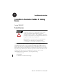
1
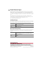
Installation Instructions
ControlNet-to-Foundation Fieldbus H1 Linking
Device
Catalog 1788-CN2FF
Product Overview
ATTENTION
The 1788-CN2FF module ships from the factory with
configuration switches set to “ON (RESET)”. With switches
“ON”, any configuration data would be reset on Power
interruption. Set the switches to “OFF (NORMAL)” after initial
power-up (to clean any Factory test configurations) but before you
configure the module with your application.
Remove power to the module before resetting configuration
switches. For more information on configuration refer
to Configuring the 1788-CN2FF Linking Device on page 9.
The ControlNet-to-Foundation Fieldbus H1 linking device (1788-CN2FF) connects a
ControlNet™ network with one or two FOUNDATION Fieldbus H1 (Fieldbus) networks.
Each H1 network consists of multiple Fieldbus devices. Each field device has one or more
function blocks. Each function block performs an elementary control function such as analog
input, analog output, discrete input, or discrete output. The ControlNet network consists of
controllers, such as PLC® processors, HMIs, drives, I/O devices, and so on. The
1788-CN2FF has three broad functions, supporting the following:
• closed-loop control
• configuration
• a redundant ControlNet network design
Publication 1788-IN051D-EN-P - February 2004
2
ControlNet-to-Foundation Fieldbus H1 Linking Device
Use this document as a guide when you install the 1788-CN2FF module.
For information about:
Refer to page:
Important User Information
4
Handling the 1788-CN2FF Module
6
System Requirements
6
1788-CN2FF Hardware Description
7
Installation Considerations
7
Power Conditioning
8
Configuring the 1788-CN2FF Linking Device
9
Installing the 1788-CN2FF
10
Removing the 1788-CN2FF
11
Connecting Power
12
Connecting to the ControlNet Network
13
Interpreting the LEDs: ControlNet Network Status
15
Interpreting the LEDs: Module Status
16
Connecting to the Fieldbus Network
17
Device vs. Connection Clarifications
18
Specifications
22
Rockwell Automation Support
24
Publication 1788-IN051D-EN-P - February 2004
ControlNet-to-Foundation Fieldbus H1 Linking Device
3
Additional Information
Refer to the following publications for additional information on the NI-FBUS Configurator,
the 1788-CN2FF Linking Device, and general fieldbus solutions information.
Pub Number
Publication Title
Scope
Source
AG-140
Wiring and Installation
31.25 kbit/s, Voltage
Mode, Wire Medium
Application Guide
Overview of what you need to
know to wire, power, and
layout network components
AG-163
31.25 kbit/s Intrinsically
Safe Systems
Complements the previous
document, introduces you to
the principles of intrinsic
safety, and outlines how to
apply approved devices in a
hazardous area.
Fieldbus Foundation
9005 Mountain Ridge Dr.,
Bowie - Suite 190
Austin, TX 78759 USA
512.794.8890
www.fieldbus.org
AG-165
Fieldbus Installation and
Planning Guide
Outlines things to consider
before installing a Fieldbus
network
1788-UM052
NI-FBUS Configurator
User Manual
Provides the information you
need to use the NI-FBUS
Configurator software.
1788-6.5.1
ControlNet to Foundation
Fieldbus User Manual
Provides the information about
the 1788-CN2FF module.
1757UM006
Fieldbus Solutions for
Rockwell Automation’s
Integrated Architecture
Overview of integrating
fieldbus into ProcessLogix,
ControlLogix and PLC5.
Rockwell Automation
www.theautomationbookstore
.com
Publication 1788-IN051D-EN-P - February 2004
4
ControlNet-to-Foundation Fieldbus H1 Linking Device
Important User Information
Solid state equipment has operational characteristics differing from those of electromechanical equipment.
Safety Guidelines for the Application, Installation and Maintenance of Solid State Controls (Publication
SGI-1.1 available from your local Rockwell Automation sales office or online at
http://www.ab.com/manuals/gi) describes some important differences between solid state equipment and
hard-wired electromechanical devices. Because of this difference, and also because of the wide variety of
uses for solid state equipment, all persons responsible for applying this equipment must satisfy themselves
that each intended application of this equipment is acceptable.
In no event will Rockwell Automation, Inc. be responsible or liable for indirect or consequential damages
resulting from the use or application of this equipment.
The examples and diagrams in this manual are included solely for illustrative purposes. Because of the many
variables and requirements associated with any particular installation, Rockwell Automation, Inc. cannot
assume responsibility or liability for actual use based on the examples and diagrams.
No patent liability is assumed by Rockwell Automation, Inc. with respect to use of information, circuits,
equipment, or software described in this manual.
Reproduction of the contents of this manual, in whole or in part, without written permission of Rockwell
Automation, Inc. is prohibited.
Throughout this manual we use notes to make you aware of safety considerations.
WARNING
Identifies information about practices or circumstances that can cause an explosion
in a hazardous environment, which may lead to personal injury or death, property
damage, or economic loss.
IMPORTANT
Identifies information that is critical for successful application and understanding of
the product.
ATTENTION
Identifies information about practices or circumstances that can lead to personal
injury or death, property damage, or economic loss. Attentions help you:
• identify a hazard
• avoid a hazard
• recognize the consequence
SHOCK HAZARD
BURN HAZARD
Labels may be located on or inside the drive to alert people that dangerous voltage
may be present.
Labels may be located on or inside the drive to alert people that surfaces may be
dangerous temperatures.
Publication 1788-IN051D-EN-P - February 2004
ControlNet-to-Foundation Fieldbus H1 Linking Device
ATTENTION
5
Environment and Enclosure
This equipment is intended for use in a Pollution Degree 2 industrial
environment, in overvoltage Category II applications (as defined in
IEC publication 60664-1), at altitudes up to 2000 meters without
derating.
This equipment is considered Group 1, Class A industrial equipment
according to IEC/CISPR Publication 11. Without appropriate
precautions, there may be potential difficulties ensuring
electromagnetic compatibility in other environments due to conducted
as well as radiated disturbance.
This equipment is supplied as “open type” equipment. It must be
mounted within an enclosure that is suitably designed for those
specific environmental conditions that will be present and
appropriately designed to prevent personal injury resulting from
accessibility to live parts. The interior of the enclosure must be
accessible only by the use of a tool. Subsequent sections of this
publication may contain additional information regarding specific
enclosure type ratings that are required to comply with certain product
safety certifications.
See NEMA Standards publication 250 and IEC publication 60529, as
applicable, for explanations of the degrees of protection provided by
different types of enclosure. Also, see the appropriate sections in this
publication, as well as the Allen-Bradley publication 1770-4.1
(“Industrial Automation Wiring and Grounding Guidelines”), for
additional installation requirements pertaining to this equipment.
Publication 1788-IN051D-EN-P - February 2004
6
ControlNet-to-Foundation Fieldbus H1 Linking Device
Handling the 1788-CN2FF Module
ATTENTION
Preventing Electrostatic Discharge
This equipment is sensitive to electrostatic discharge, which can cause
internal damage and affect normal operation. Follow these guidelines
when you handle this equipment:
•
•
•
•
•
•
Touch a grounded object to discharge potential static.
Wear an approved grounding wriststrap.
Do not touch connectors or pins on component boards.
Do not touch circuit components inside the equipment.
If available, use a static-safe workstation.
When not in use, store the equipment in appropriate static-safe
packaging.
System Requirements
This section describes the required hardware and software components you need before you
can use the 1788-CN2FF. You should also review the README.TXT file on the setup disk
for the latest information.
Hardware
• ControlNet-to-Foundation Fieldbus H1 linking device, 1788-CN2FF module
• PC ControlNet interface: 1784-KTCX15, 1784-PCC, 1784-PCIC
• ControlNet and Fieldbus cabling
Software
The following software is necessary to configure the Fieldbus devices and the 1788-CN2FF
using ControlNet.
• Windows NT 4.0, service pack 6 or Windows 2000, service pack 3 or higher
• NI-FBUS Configurator, 1788-FFCT version 2.6.0 or higher
• RSLinx OEM 2.40.00 (build 16) or later, RSLinx Lite is not sufficient.
Other Software
To use the 1788-CN2FF module with RSLogix 5000 and a ControlLogix controller you will
need:
• RSLogix 5000 version 11.11 or later
• RSNetWorx for ControlNet version 4.01.00 (build 04) or later
To use the 1788-CN2FF module with ProcessLogix, refer to:
• The ProcessLogix Installation and Upgrade Guide.
• Knowledge Builder
Publication 1788-IN051D-EN-P - February 2004
ControlNet-to-Foundation Fieldbus H1 Linking Device
7
1788-CN2FF Hardware Description
Figure 1 ControlNet-to-Foundation Fieldbus Linking Device
1
2
3
1. ControlNet A and B BNC
Connectors, to support single or
redundant network topologies.
4
2. Case/Enclosure
9
3. ControlNet Network Status LEDs
1
4. Non-isolated ControlNet Network
Access Port (NAP)
5. Power Supply Connector
10
6. DIN Rail Clip
7. ControlNet Module STATUS LED
8
8. Fieldbus Connectors
5
7
43163
6
9. Network Address Switches
(under cover)
10. Not Used
Installation Considerations
The 1788-CN2FF is designed to be mounted on a 35 mm DIN rail. The device dimensions
are 4.375 x 4.375 and is 4.5 inches high. ControlNet connectors are on top of the unit, allow
1.5 inches for the connectors.
IMPORTANT
Make sure that the power to the network is off
when connecting the module.
The CN2FF supports redundant media and a ControlNet network access port (NAP). There
are 2 (A, B) BNC ControlNet connectors. We recommend using the “A” BNC connector
when setting up a single network and then using the “B” connector for the second
(redundant) network. It does not matter, but when you are working with redundant networks,
the industry tends to refer to the primary network as A and the secondary network as B.
The ControlNet status LEDs on the front of the module display the current status of each of
the redundant media channels. The rotary switches are used to set the ControlNet network
address. You can write the network address in the space provided on front of the device.
The module has two separate Fieldbus ports which supports 2 Fieldbus networks. The power
connections are used to supply power to the CN2FF.
Publication 1788-IN051D-EN-P - February 2004
8
ControlNet-to-Foundation Fieldbus H1 Linking Device
Power Conditioning
You must use a power conditioner between your Fieldbus power supply and the Fieldbus
network. You can use a power supply designed for Foundation Fieldbus operation which has
the proper power conditioning elements. If you are using an ordinary power supply, a separate
power conditioner must also be used. If an ordinary power supply is connected directly to the
Fieldbus, the power supply would absorb signals on the cable because it would try to maintain
a constant voltage level. The power conditioner puts an inductor between the power supply
and the Fieldbus wiring. The inductor connects the DC power to the Fieldbus wiring but
prevents signals from going into the power supply.
In practice, a real inductor is not used in the power conditioner but an electronic equivalent.
The electronic inductor circuit has the added advantage of limiting the current provided to
the network segment if the cable is shorted.
The voltage supplied to the Fieldbus cable can be as high as 32 V. The voltage at any device
can be as low as 9 V for the device to operate correctly. A typical Fieldbus device takes about
20 mA of current from the cable. The Fieldbus is configured so that one of the wires has a
(+) voltage, the other wire has a (-) voltage and the shield is grounded.
A cable with the orange wire as plus and the blue wire as minus is shown above. This type of
cable is available from Fieldbus cable manufacturers. Other cables or existing plant wiring
conventions may be different. Regardless of the color convention, keep the sense of Fieldbus
polarity consistent throughout the plant.(1)
IMPORTANT
We suggest that you not use White/Black or White/Red pairs since
they may be mistaken for 115 volt power wiring.
Be sure to follow the wiring and installation requirements in the Foundation Fieldbus
publications listed in the section Additional Information on page 3.
(1)
RELCOM inc., Fieldbus Wiring Design and Installation Guide (2221 Yew Street, Forest Grove, OR 97116) p. 5. Reprinted by
permission.
Publication 1788-IN051D-EN-P - February 2004
ControlNet-to-Foundation Fieldbus H1 Linking Device
9
Configuring the 1788-CN2FF Linking Device
ATTENTION
The 1788-CN2FF module ships from the factory with
configuration switches set to “ON (RESET)”. With switches
“ON”, any configuration data would be reset on Power
interruption. Set the switches to “OFF (NORMAL)” after initial
power-up (to clean any Factory test configurations) but before you
configure the module with your application.
Remove power to the module before resetting configuration
switches.
The CN2FF has three configuration switches accessible from an opening in the bottom of
the module. These switches are illustrated in Figure 2.
Figure 2 The 1788-CN2FF Configuration Switches
(UNUSED)
ON (RESET)*
OFF (NORMAL)
OFF
(UNUSED)
OFF
top of module
back of module
* When set to ON (RESET), this switch causes
the device to reset all configuration
information to factory defaults at a power
cycle. To resume normal operation, this
switch must be set to OFF.
Publication 1788-IN051D-EN-P - February 2004
10
ControlNet-to-Foundation Fieldbus H1 Linking Device
Installing the 1788-CN2FF
The CN2FF has a rugged, simple clip for mounting reliably on a standard
35mm DIN rail. Follow these steps to mount the module onto a DIN rail.
1. Use a flat-bladed screwdriver to open the DIN Rail Clip to the unlocked position.
Rail Clip Locked
Rail Clip Unlocked
43167
2. Hook the lip on the rear of the module onto the top of a 35mm DIN rail and press
the module down onto the DIN rail.
DIN Rail
Cover
Press
43168
3. Slide the module to the desired position on the DIN rail. After it is in position, push
the rail clip into the locked position to lock it in place on the DIN rail.
Publication 1788-IN051D-EN-P - February 2004
ControlNet-to-Foundation Fieldbus H1 Linking Device
11
Figure 3 Install the 1788-CN2FF on to the DIN Rail
DIN Rail
Rail Clip Unlocked
Position Device Along DIN Rail
Rail Clip Locked
43169
Removing the 1788-CN2FF
To remove a module, unlock it from the DIN rail by placing a screwdriver in the slot on the
rail clip and opening the rail clip to the unlocked position as shown in step 1 on page 10.
Then lift the device off of the rail.
Publication 1788-IN051D-EN-P - February 2004
12
ControlNet-to-Foundation Fieldbus H1 Linking Device
Connecting Power
The 1788-CN2FF requires 15-30V dc power and the cable is limited to a maximum of 3m in
length. One power supply can support several CN2FFs. The power connector is a 6-pin
screw terminal connector. The pinout for the power connector is shown in Figure 4.
IMPORTANT
Make sure that the power to the network is off when
connecting the module.
Figure 4 Power Connector Pinout
15-30 V dc Backup
Power Supply
+
(optional)
–
v v
v
To adjacent device
c c
c
15-30 V dc
Primary Power
Supply
+
43170
V (optional connection)
C
–
Connect the primary power supply to the center V and C pair. An optional backup power
supply may be connected to the left V and C pair. The right V and C pair may be used to
chain the primary power supply to other devices. All three terminals labeled C are connected
in the CN2FF. The right two V terminals are connected in the CN2FF. These connections are
indicated on the power connector by the lines over the V and C terminals.
Publication 1788-IN051D-EN-P - February 2004
ControlNet-to-Foundation Fieldbus H1 Linking Device
13
Connecting to the ControlNet Network
There are two types of ControlNet connectors on the CN2FF, the BNC and the RJ-45.
Using the BNC:
• BNC connectors are for direct connection to a ControlNet network through a tap.
• BNC connectors must be used to connect the CN2FF to the ControlNet network.
Using the RJ-45:
• The RJ-45 connector is a network access port (NAP).
• This port is provided for configuration and development use only and it is not
intended for long term use.
• Maximum length of the cable connecting the NAP to the CN2FF is limited to 30m.
• When not in use remove the NAP port connection.
Do not connect the 1788-CN2FF to more than one ControlNet
IMPORTANT
network at a time. Attempting to connect to a second network will cause
the CN2FF to operate erratically.
Figure 5 Typical 1788-CN2FF Connections to a Redundant ControlNet Network
Linking Device
Warning
A
Redundant
ControlNet
Networks
A is typically used
for single
networks and add
B for redundancy.
B
ControlNet
Device
The RJ-45 connector, NAP
port is for temporary use
only, not for production
monitoring. This port is not
intended for long term use.
When not in use remove the
NAP port connection.
ControlNet
Device
Publication 1788-IN051D-EN-P - February 2004
14
ControlNet-to-Foundation Fieldbus H1 Linking Device
Setting the ControlNet Network Address
Valid ControlNet network addresses are 1-99. Network address zero is reserved. Switch 1
controls the most significant decimal digit (the tens). Switch 2 controls the least significant
decimal digit (the ones). Figure 6 shows the location of the network address switches and an
example of switch settings for a network address of 15.
Figure 6 ControlNet Network Address Switches Set to 15
9 01
9 01
456
23
456
23
78
78
43164
Switch Cover
(Removed)
9 01
9 01
23
456
456
23
SW 2
78
SW 1
78
Follow these steps to set the ControlNet network address for the 1788-CN2FF.
1. Choose and set a network address.
2. Write the network address setting in the space provided on the CN2FF label.
3. Apply (or cycle) power to the CN2FF to enable the new network address.
4. Make the same address changes in your NI-FBUS configuration software.
Publication 1788-IN051D-EN-P - February 2004
ControlNet-to-Foundation Fieldbus H1 Linking Device
15
Interpreting the LEDs: ControlNet Network Status
The ControlNet network status LEDs are located on the front of the 1788-CN2FF, beside
the ControlNet BNC connectors, as shown in Figure 1, Item 3. They indicate the state of the
ControlNet connected to the BNC connectors. These LEDs do not reflect anything about
the status of the network access port (NAP). If more than one state is present, the LEDs
always reflect the highest priority status present on the network. Table 7 describes the LED
states and the priority of each status.
Table 7 ControlNet Network LED Status Descriptions
LED State
Priority
How to View
Cause
Both steady off
1 (highest)
View together
Reset or no power
Both steady red
2
Failed to link interface to ControlNet
Alternating red & green
3
Self testing
Alternating red
4
Bad node configuration (such as duplicate
ControlNet network address)
Steady off
5
Flashing red & green
6
Flashing red
7
Link fault or no frames received
Flashing green
8
Temporary channel error or listen only
Steady green
9 (lowest)
Normal operation
View
independently
Channel disabled or not supported
Invalid link configuration
Publication 1788-IN051D-EN-P - February 2004
16
ControlNet-to-Foundation Fieldbus H1 Linking Device
Interpreting the LEDs: Module Status
The STATUS LED is located on the front of the 1788-CN2FF, between the two Fieldbus
connectors, as shown in Figure 1, Item 7. It indicates whether the CN2FF is powered,
configured, and operating properly. Table 8 shows how to interpret the STATUS LED states.
Table 8 Module Status LED State Descriptions
LED State
Description
Off
No power to the CN2FF
Flashing red and green
CN2FF self testing
Flashing green
Standby state(1)
Solid green
Operational state(2)
Flashing red
Major recoverable fault
Solid red
Major unrecoverable fault
(1)
Standby state indicates the CN2FF has passed all self tests and is ready to operate.
Yet, it is not functioning because it is not been configured.
(2)
Operational state indicates the CN2FF has left standby state because the necessary
network configuration (if any) has occurred.
Publication 1788-IN051D-EN-P - February 2004
ControlNet-to-Foundation Fieldbus H1 Linking Device
17
Connecting to the Fieldbus Network
Figure 9 Fieldbus Connector Locations on the 1788-CN2FF
43171
Fieldbus Connections
Use pins 6 and 7 for the Fieldbus signals, as specified in the Fieldbus Standard for Use in
Industrial Control Systems, Part 2, ISA-S50.02.1992. Refer to Figure 10 for the connector pinout
of the 1788-CN2FF.
IMPORTANT
Make sure that the power to the network is off when
connecting the module.
Figure 10 Fieldbus Connector Pinout for the 1788-CN2FF
NC
NC
NC
NC
NC
1
2
3
4
5
6
7
8
9
Data +
Data –
NC
NC
43172
Publication 1788-IN051D-EN-P - February 2004
18
ControlNet-to-Foundation Fieldbus H1 Linking Device
Device vs. Connection Clarifications
This section describes the functional relationship and differences between 1788-CN2FF
Connections and Foundation FieldbusΤΜ Devices. A connection does not always equal a
device.
ATTENTION
The maximum number of “connections” is 30 per CN2FF. The
recommended number of “devices” is 8 per H1 port on the
CN2FF. If you exceed the maximum number of connections or
the recommended number of devices, system performance could
be compromised.
• A connection is considered any link (wire connection) to:
•
•
•
•
CNAI, ControlNet ANALOG INPUT
CNAO, ControlNet ANALOG OUTPUT
CNDI, ControlNet DIGITAL INPUT
CNDO, ControlNet DIGITAL OUTPUT
• A device is considered a specific Foundation Fieldbus device such as a
transmitter.
For each different network configuration, you must account for all connections and devices
toward the maximum recommendations.
Publication 1788-IN051D-EN-P - February 2004
ControlNet-to-Foundation Fieldbus H1 Linking Device
19
1788-CN2FF Connections
A connection is considered any link (wire connection) to a CNAI, CNAO, CNDI, and
CNDO. When using the CNAO, refer to the graphic below that illustrates there are two
connections for each CNAO.
For help in determining the number of connections on a port, refer to the Device Info screen
once you have downloaded the function block applications to the CN2FF.
Publication 1788-IN051D-EN-P - February 2004
20
ControlNet-to-Foundation Fieldbus H1 Linking Device
To locate the Device Info, expand the CN2FF tree and double-click on Device Info.
When
accounting
for the
number of
connections,
you need to
count the
number of
Tags in the
FieldbusTag
column and
not the
number
identifying
the
Instances.
Even though
there is a
duplicate
Instance of 1, it
is still counted as
a separate
FieldbusTag that
counts against
the total 30
connections. This
example has 12
connections.
Each tag in the FieldbusTag column counts as a fieldbus connection. There can be duplicate
Instance numbers for different types of modules (e.g. DI vs. AI).
On any one port you can have up to a maximum of 18 connections. If you are using 18
connections on one port, the second port would only be allowed 12 connections for a total of
30 per CN2FF.
Publication 1788-IN051D-EN-P - February 2004
ControlNet-to-Foundation Fieldbus H1 Linking Device
21
1788-CN2FF and Foundation Fieldbus Devices
Devices do not equate to connections. The current recommended number of devices per H1
port is 8 and the maximum number of devices per 1788-CN2FF module is 16 for any type of
bus power used.
ATTENTION
The maximum number of “connections” is 30 per CN2FF. The
recommended number of “devices” is 8 per H1 port on the
CN2FF. If you exceed the maximum number of connections or
the recommended number of devices, system performance could
be compromised.
These numbers are for Non-IS (Intrinsically Safe) class devices only. IS device maximums are
even lower, depending on all the configuration constraints of a particular application.
Understanding the 1788-CN2FF Connection and Device Relationship
One connection does not equal one device. The maximum recommended number of devices
per each H1 port is 8 for a total 16. That maximum takes into account that you have an
optimal sized network, the correct number of connections, followed wiring guidelines and
you don’t have 16 devices that exceed the current limitation of your systems’ power supply.
Many devices require 2 connections (e.g. an AO) and some devices that can require 3 or more
connections (e.g. a PID). The number of connections needs be considered when counting
devices. You may have 8 devices that exceed the connection limits of the module. For
example: AIs take one connection, AOs will require two, and PIDs will need at least 2 but
could use more depending on how it is wired.
The maximum number of connections (30) is specified as a combination for BOTH channels.
In addition, you need to account for other process aspects such as loop time and stale limits
for your network segments. You need to take into account the length of your cables and spurs,
the number of devices per spur, power consumption of each device, etc.
ATTENTION
Be sure to follow the wiring and installation requirements in the
Foundation Fieldbus publications listed in the section Additional
Information on page 3.
Publication 1788-IN051D-EN-P - February 2004
22
ControlNet-to-Foundation Fieldbus H1 Linking Device
Specifications
Type
Specifications
Operating Temperature
0 to 60°C (32 to 140°F)
IEC 60068-2-1 (Test Ad, Operating Cold),
IEC 60068-2-2 (Test Bd, Operating Dry Heat),
IEC 60068-2-14 (Test Nb, Operating Thermal Shock)
Storage Temperature
–40 to 85°C (–40 to 185°F)
IEC 60068-2-1 (Test Ab, Un-packaged Non-operating Cold),
IEC 60068-2-2 (Test Bb, Un-packaged Non-operating Dry Heat),
IEC 60068-2-14 (Test Na, Un-packaged Non-operating Thermal Shock)
Relative Humidity
5 to 95% non-condensing
IEC 60068-2-30 (Test Db, Un-packaged Non-operating Damp Heat)
Vibration
IEC60068-2-6 (Test Fc, Operating): 2g @ 10-500Hz
Physical Dimensions
4.375 in. x 4.375 in x 4.5 in
• ControlNet connectors are on top of the unit
• Allow 1.5 inches for the connectors.
Shock
IEC60068-2-27 (Test Ea, Unpackaged shock):
Operating 30g
Non-operating 50g
Emissions
CISPR 11: Group 1, Class A
ESD Immunity
IEC 61000-4-2:
4kV contact discharges
8kV air discharges
Radiated RF Immunity
IEC 61000-4-3:
10V/m with 1kHz sine-wave 80%AM from 30MHz to 1000MHz
10V/m with 200Hz 50% Pulse 100%AM at 900Mhz
EFT/B Immunity
IEC 61000-4-4: ±2kV at 5kHz on signal ports
Surge Transient Immunity
IEC 61000-4-5: ±1kV line-line(DM) and ±2kV line-earth(CM) on signal ports
Conducted RF Immunity
IEC 61000-4-6: 10Vrms with 1kHz sine-wave 80%AM from 150kHz to 80MHz
Magnetic Field Immunity
IEC 61000-4-8: 30A/m at 50Hz
Enclosure Type Rating
None (open-style)
Communication
•
•
•
•
•
ControlNet - redundant media
NAP, network access port
FOUNDATION Fieldbus H1, 2 independent channels
LAS on both channels
Time Master on both channels
Mounting
35 mm DIN rail
Power Requirements
Class 2 power supply 24V dc
15-30V dc
270 mA @ 24V dc (typical)
Publication 1788-IN051D-EN-P - February 2004
ControlNet-to-Foundation Fieldbus H1 Linking Device
Type
Specifications
Indicators
• Module Status
• ControlNet Status, 1 each connection
Connectors
•
•
•
•
•
Conductors
23
Wire Size
Category
Certifications
(when product is marked)
ControlNet - BNC connectors, provides redundancy
two 10-position rotary switches
Network Access Port - RJ45 (non-isolated)
Fieldbus - 9-pin sub-D connectors
Power Input Terminals:
-Torque 5-7 in-lb.
-Not to be used with combination of solid and stranded 16 GA wire
#22 AWG (0.355 SQmm) Copper Stranded wire to #14 AWG (2.08 SQmm)
Copper Stranded wire
60° C minimum
2(1) (2)
c-UL-us
FCC
C-Tick(3)
CE(3)
UL Listed Industrial Control Equipment, certified for US and
Canada
North American EMI Verification
Part 15-Class A-ICES003
Australian EMC Compliance
AS/NZS CISPR 11; Industrial Emissions
European Union 89/336/EEC EMC Directive, compliant with:
EN 61000-6-4; Industrial Emissions
EN 50082-2; Industrial Immunity
EN 61326;
Meas./Control/Lab., Industrial Requirements
EN 61000-6-2; Industrial Immunity
(1)
Use this Conductor Category information for planning conductor routing. Refer to Publication 1770-4.1, “Industrial
Automation Wiring and Grounding Guidelines”.
(2)
Appropriate shielded cable is required for Electromagnetic compatibility (EMC) standards.
(3)
See the Product Certification link at www.ab.com for Declarations of Conformity, Certificates, and other certification details.
Allen-Bradley and ProcessLogix are trademarks of Rockwell Automation.
RSLinx, RSLinx OEM, RSNetWorx are trademarks of Rockwell Software.
Foundation Fieldbus is a trademark of the Fieldbus Foundation.
Windows NT and 2000 are trademarks of the Microsoft Corporation.
Publication 1788-IN051D-EN-P - February 2004
Rockwell Automation Support
Rockwell Automation provides technical information on the web to assist you in using our
products. At http://support.rockwellautomation.com, you can find technical manuals, a
knowledge base of FAQs, technical and application notes, sample code and links to software
service packs, and a MySupport feature that you can customize to make the best use of these
tools.
For an additional level of technical phone support for installation, configuration and
troubleshooting, we offer TechConnect Support programs. For more information, contact
your local distributor or Rockwell Automation representative, or visit
http://support.rockwellautomation.com.
Installation Assistance
If you experience a problem with a hardware module within the first 24 hours of installation,
please review the information that's contained in this manual. You can also contact a special
Customer Support number for initial help in getting your module up and running:
United States
1.440.646.3223
Monday – Friday, 8am – 5pm EST
Outside United
States
Please contact your local Rockwell Automation representative for any
technical support issues.
New Product Satisfaction Return
Rockwell tests all of our products to ensure that they are fully operational when shipped from
the manufacturing facility. However, if your product is not functioning and needs to be
returned:
United States
Contact your distributor. You must provide a Customer Support case number
(see phone number above to obtain one) to your distributor in order to
complete the return process.
Outside United
States
Please contact your local Rockwell Automation representative for return
procedure.
Publication 1788-IN051D-EN-P - February 2004
Supersedes Publication 1788-IN051C-EN-P - September 2003
PN 957868-05
Copyright © 2004 Rockwell Automation. All rights reserved. Printed in the U.S.A.