1
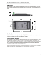
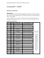
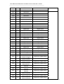
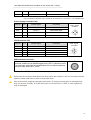
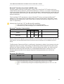
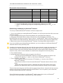
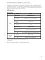
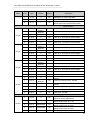
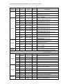
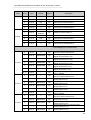
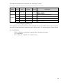
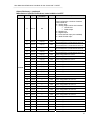
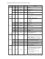
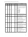
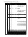
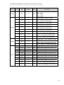
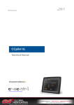
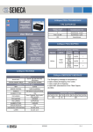
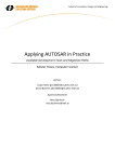
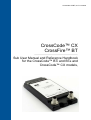
CrossCode CX/BT, rev.C.6 100823
CrossCode™ CX
CrossFire™ BT
Sub User Manual and Reference Handbook
for the CrossCode™ BTi and BTe and
CrossCode™ CX models,
User Manual and Reference Handbook for the CrossCode™ CX/BT
Table of Contents
Introduction ...............................................................................................................................................................................3
Functions and Features ........................................................................................................................................................3
Technical Data ......................................................................................................................................................................4
References ...........................................................................................................................................................................4
Dimensions ...........................................................................................................................................................................5
Identification ..........................................................................................................................................................................5
Environmental Tolerance ......................................................................................................................................................5
Installation.............................................................................................................................................................................6
Electrical Interface ....................................................................................................................................................................7
Connectors ...........................................................................................................................................................................7
Electrical Interface Overview ..............................................................................................................................................10
Electrical Interface Characteristics ......................................................................................................................................11
LED indicators ....................................................................................................................................................................20
CANopen Interface .................................................................................................................................................................21
Parameter Overview ...........................................................................................................................................................21
EMCY Object Overview ......................................................................................................................................................22
Receive PDOs: Digital Outputs, Analog (PWM) Outputs ....................................................................................................22
Transmit PDOs: Digital Inputs and Analog Inputs ...............................................................................................................23
Object Dictionary ................................................................................................................................................................26
Appendix 1 – Environmental Tolerances ................................................................................................................................41
Technical Support ...................................................................................................................................................................42
Trade Mark, etc. ......................................................................................................................................................................43
Index .......................................................................................................................................................................................44
2
User Manual and Reference Handbook for the CrossCode™ CX/BT
CrossCode™ CX/BT
Introduction
The CrossCode™CX CrossFire™ BT is a compact, ruggedised and versatile I/O-module
designed for mobile applications. The module is intended for HMI-related I/O (Human-Machine
Interface Inputs and Outputs), typically found in a vehicle cabin, a control panel or a handheld
remote control unit.
The Module is available in three versions: The CrossFire™ CX, the CrossCode™ BTi and the
CrossCode™ BTe. The CrossCode™ BTi and CrossCode™ BTe have a wireless Bluetooth®
interface, but the CrossCode™ CX does not. The difference between the BTi and BTe versions
is that the BTi has an internal antenna, and the BTe has an external antenna.
This manual will use the name CrossCode™ CX/BT whenever information is relevant to all
three versions of the CrossCode™. CrossCode™ BT refers to both the BTi and the BTe.
This manual describes how the CrossCode™ CX/BT should be used. The reader should be
familiar with the CANopen standard in order to fully understand the manual.
Functions and Features
The CrossCode™ CX/BT is a CiA DS 401 I/O module, designed for mobile
products such as handheld devices. It has 53 I/O ports which can be individually
configured to provide various types of I/O, intended for HMI-related signals such
as joysticks, rotary knobs, pushbuttons, LED drivers and instrumentation lighting.
The CrossCode™ CX/BT can therefore be configured to have:
- Up to 35 Digital Outputs
- Up to 35 Digital Inputs
- Up to 8 Analog Inputs with 2 software-selectable ranges: 0-5V or 0-28
V.
- 17 Analog Outputs (LED Drivers)
- 1 PWM (Pulse-Width Modulated) Output intended for a Backlight
Driver
- 4 Shaft Encoder Inputs (2 pairs)
There are 4 ports for providing power to other devices.
- 2 joystick power supply outputs (5 V)
- 2 peripheral power supply outputs (9 – 32 V)
Configurable using SDOs (Service Data Object)
7 statically-mapped PDOs (Process Data Objects) compliant to DS 401
Supports use of synch object
Support for both heartbeat and node guarding
The CrossCode™ CX/BT is an EMCY object producer. The COB ID
(Communication Object Identifier) of the EMCY object can be configured.
Storage for up to 127 Error codes
Reset function restores settings back to their factory default values.
Bluetooth® Class 1 wireless serial interface (CrossCode™ BT only)
3
User Manual and Reference Handbook for the CrossCode™ CX/BT
Technical Data
Processor
Physical
Housing
Dimensions
Weight
Environment
Temperature Range
Protection rating
EMC Conformity
Power Supply
Operating voltage
Current consumption
Indicators
CAN interface
Communication profile
Device Profile
Baud Rate
Node ID
Bluetooth® Interface
Range
Baud Rate
Connectors
Digital Inputs
Input Voltage
Digital Outputs
Max Voltage
Max Current
Protection
Digital Encoder Inputs
Voltage
Protection
Analog Inputs
Input Voltage
Input impedance
Resolution
Conversion Error
Protection
Analog Outputs (LED Drivers)
PWM (Analog) Output
Max Voltage
Max Current
Protection
Power Outputs
Voltage
Max Current
Approvals / Certifications
Fujitsu MB90F
Plastic enclosure filled with silicon compound
L x W x H: 175 x 82 x 32 mm (48 - 60 mm with attached cables)
375 g
Operating: -40 ˚C to +75 ˚C
IP67 (IEC 60529)
ISO 14982 for Emissions, ISO 11452-2 for Immunity
9 to 32 VDC
<50 mA at 24V without external load
One red/green LED indicator.
ISO 11898-2 (High Speed CAN)
CANopen
I/O module to CiA DS401
20, 50, 100, 125, 250, 500, 800 and 1000 kbit/s
1 to 8 set with connector key, or 1 to 127 set with SDOs
Wireless serial interface via Bluetooth®, Class 1
100 meters
1 Mbit/s
I/O: 62 pole D-SUB
CAN: DIN M12
Power: DIN M12
0 – 5 V / 0 – 32 V
0–5V
4 mA
Over-current Protection
0 – 5 V, 0 – 36 V
Over-voltage Protection
0 – 5 V or 0 – 28 V
1 MΩ or 12.2 kΩ
10 bits
+/-3 LSB
Over-voltage Protection
Low-side drivers with independent intensity settings
9 – 32 V
1A
Short Circuit Protection
Joystick:
Peripheral:
5 VDC,
9 – 32 VDC depending on power supplied
0.3 A,
0.1 A
References
Bluetooth:
CAN in Automation - CANopen standard:
CE Marking:
International Standards Organisation:
International Electrotechnical Commission
http://www.bluetooth.com/
http://www.can-cia.org
http://ec.europa.eu/
http://www.iso.org/
http://www.iec.ch/
4
User Manual and Reference Handbook for the CrossCode™ CX/BT
Dimensions
20
32
The CrossCode™ CX/BT dimensions and placement of the four mounting holes are illustrated
below. The four mounting lugs have clearance holes for 3.5 mm bolts. The module weighs 375
grams.
82
26.5
74
175
3.5 x 4
167
Identification
There is a label on the front of the CrossCode™ CX/BT. On the label there are numbers which
identify your unique module. Take note of them. During service and other contact with the
supplier it is important to be able to provide these numbers.
Environmental Tolerance
The CrossCode™ CX/BT has been designed to cope with tough environmental demands. Strict
tests have been conducted on the unit in order to ensure that it fulfils the expectations of a
rugged unit. Much work has been performed to choose and design integral components so that
they, in the best possible way and under all circumstances, provide you with a dependable
working instrument. In Appendix 1, a list of standards can be found according to which the
CrossCode™ CX/BT has been tested and approved.
Despite thorough design requirements and testing specifications, it is always best to install and
handle the CrossCode™ CX/BT with care. For more information, read further.
5
User Manual and Reference Handbook for the CrossCode™ CX/BT
Installation
Your CrossCode™ CX/BT should be installed in such a way that the module is not exposed to
any unnecessary stress, heat, vibration or moisture. In this section, some recommendations are
made regarding methods for how the unit should be installed.
If the unit is opened by non-authorised personnel, the warranty becomes void.
Cooling
Although the CrossCode™ CX/BT can operate in relatively high temperatures, cooling should
still be considered when installing the CrossCode™ CX/BT. If the unit becomes too warm, it
may not perform to its full capacity and, with high temperature, cease to function.
Inadequate cooling may lead to overheating, causing permanent damage to the unit.
Vibration
We recommend installing the CrossCode™ CX/BT in such a way that it is not unnecessarily
exposed to vibration or other stress.
Rain / Moisture
The CrossCode™ CX/BT shall preferably be covered or enclosed in order to prevent direct
exposure to water.
6
User Manual and Reference Handbook for the CrossCode™ CX/BT
CrossCode™ CX/BT
Electrical Interface
Connectors
Every I/O pin on the CrossCode™ CX/BT is assigned a unique port. The ports are numbered
from 1 to 62. Every port may be configured individually in software to one of 6 different I/O
types. Not all I/O types are available on all ports. Some ports are reserved for power/GND and
have no I/O capabilities.
The port assignments of the CrossCode™ CX/BT are the same as the pin assignments on
connector X3. The terms “port” and “pin” may therefore be used interchangeably whenever
connector X3 is concerned.
62-pole I/O Connector (X3)
Conn.Pin
Port
Default Signal
Other Configurations
X3.1
1
Encoder Input, Shaft 1, A
Digital Input, Digital Output
X3.2
2
Encoder Input, Shaft 1, B
Digital Input, Digital Output
X3.3
3
Encoder Input, Shaft 2, A
Digital Input, Digital Output
X3.4
4
Encoder Input, Shaft 2, B
Digital Input, Digital Output
X3.5
5
Analog Input
Digital Input, Digital Output
X3.6
6
Analog Input
Digital Input, Digital Output
X3.7
7
Analog Input
Digital Input, Digital Output
X3.8
8
Analog Input
Digital Input, Digital Output
X3.9
9
Analog Input
Digital Input, Digital Output
X3.10
10
Analog Input
Digital Input, Digital Output
X3.11
11
Analog Input
Digital Input, Digital Output
X3.12
12
Analog Input
Digital Input, Digital Output
X3.13
13
GND
X3.14
14
+5 Vcc
X3.15
15
LED Driver
X3.16
16
LED Driver
X3.17
17
LED Driver
X3.18
18
LED Driver
X3.19
19
LED Driver
X3.20
20
LED Driver
X3.21
21
LED Driver
X3.22
22
LED Driver
X3.23
23
LED Driver
X3.24
24
LED Driver
D-SUB, female,
62-pole
7
User Manual and Reference Handbook for the CrossCode™ CX/BT
X3.25
25
LED Driver
X3.26
26
LED Driver
X3.27
27
LED Driver
X3.28
28
LED Driver
X3.29
29
LED Driver
X3.30
30
LED Driver
X3.31
31
Bluetooth® Status LED*
X3.32
32
GND
X3.33
33
PWM Output
X3.34
34
GND
X3.35
35
+24 VBATT
X3.36
36
Digital Input
Digital Output
X3.37
37
Digital Input
Digital Output
X3.38
38
Digital Input
Digital Output
X3.39
39
Digital Input
Digital Output
X3.40
40
Digital Input
Digital Output
X3.41
41
Digital Input
Digital Output
X3.42
42
Digital Input
Digital Output
X3.43
43
Digital Input
Digital Output
X3.44
44
Digital Input
Digital Output
X3.45
45
Digital Input
Digital Output
X3.46
46
Digital Input
Digital Output
X3.47
47
Digital Input
Digital Output
X3.48
48
Digital Input
Digital Output
X3.49
49
+5 Vcc
X3.50
50
GND
X3.51
51
X3.52
52
X3.53
53
X3.54
54
X3.55
55
X3.56
56
X3.57
57
X3.58
58
X3.59
59
X3.60
60
Bluetooth®
Channel selection**
Bluetooth®
Channel selection**
Bluetooth®
Channel selection**
Bluetooth®
Role selection**
CAN Baud Rate
selection
CAN Baud Rate
selection
CAN Baud Rate
selection
CANopen
Node ID selection
CANopen
Node ID selection
CANopen
Node ID selection
LED Driver
Digital Input, Digital Output
Digital Input, Digital Output
Digital Input, Digital Output
Digital Input, Digital Output
Digital Input, Digital Output
Digital Input, Digital Output
Digital Input, Digital Output
Digital Input, Digital Output
Digital Input, Digital Output
Digital Input, Digital Output
8
User Manual and Reference Handbook for the CrossCode™ CX/BT
X3.61
X3.62
61
GND
62
+24 VBATT
*for CrossCode™ BTe/BTi only. Default for CrossCode™ CX Port 31 is LED Driver.
**for CrossCode™ BTe/BTi only. Default for CrossCode™ CX Ports 51 – 54 is Digital Input.
Power Supply Connector (X1)
Conn.Pin
Port
Default Signal
Comments
X1.1
-
+24 VBATT
Main Power Input
X1.2
-
+24 VBATT
Main Power Input
X1.3
-
GND
Main Ground Input
X1.4
-
GND
Main Ground Input
DIN M12 x 1
male, 4-pole,
A-coded
2
3
1
4
CAN Connector (X2)
Conn.Pin
Port
Default Signal
Comments
X2.1
X2.2
X2.3
X2.4
-
CAN Shield
+24 VBATT
GND
CANH
Alternative Power Input
Alternative Ground Input
X2.5
-
CANL
SMA Antenna Connector*
This connector is used to attach an external bluetooth antenna. Only
antennas certified to use with Bluegiga circuit (WT11) should be used.
If an extension cable shall be used between the unit and the antenna,
choose a cable suited for 2,4 GHz.
DIN M12 x 1
male, 5-pole,
B-coded
2
3
5
1
4
SMA, Female
*for CrossCode™ BTe only.
Notice that the connector illustrations are those which are located on the unit, not those that the
attached cables shall have in order to mate with them.
Use caution when plugging/unplugging connectors. If the pins become bent or damaged they
may not function correctly, or in the worst case, the CrossCode™ CX/BT or other equipment
may be damaged.
9
User Manual and Reference Handbook for the CrossCode™ CX/BT
Electrical Interface Overview
The CrossCode™ CX/BT is highly configurable. The following illustration consists of several
boxes which represent the main functional groups on the CrossCode™ CX/BT. The arrows
leading to and from the functional groups represent I/O, power or communication busses.
Where applicable, port configuration, voltage ranges, biases, etc. are selected by sending an
SDO to the object dictionary in the Manufacturer Specific Profile Area; index 0x2000 to 0x5FFF.
CrossCode™ CX/BT
CrossCode™ BT only
Bluetooth® Interface
CAN Interface
Bluetooth®
Network
CAN BUS
BTi: internal antenna
BTe: external antenna
Analog Outputs
(LED Drivers)
Encoder Inputs
4 Ports (1 - 4)
Also configurable as:
• 4 Digital Inputs
• 4 Digital Outputs
Individual 4-bit
intensity control
17 Ports
(15 - 31)
PWM Output
(Backlight Driver)
1 Port (33)
Analog Inputs
8 Ports (5 – 12)
Also configurable as:
• 8 Digital Inputs
• 8 Digital Outputs
Digital I/O’s
Configurable as:
• 23 Digital Inputs
• 23 Digital Outputs
By default, Ports 51 to 60
are configured to select:
®
• Bluetooth Channel*
®
• Bluetooth Role*
• CAN Baud Rate
• CANopen Node ID
23 Ports
(36-48 & 51-60)
*for CrossCode™ BT only
Power
2 x +24 VBATT
+24 VBATT
2 x 5 Vcc
10
User Manual and Reference Handbook for the CrossCode™ CX/BT
Electrical Interface Characteristics
Analog Inputs
There are eight Analog Inputs available on the CrossCode™ CX/BT. The eight inputs are all of
the same type, and as such, have identical electrical characteristics. The eight inputs are evenly
divided into 2 “Voltage Groups”. The input voltage range of Analog Inputs is configured for each
Voltage Group as a whole (voltage ranges can not be configured individually). The inputs have
a low range from 0 to 5 V and a high range from 0 to 28 V for the respective Voltage Group.
Changing the voltage range also affects the input impedance, and accuracy for the group.
Over- and under-voltage protection is provided at +5.5 V and -0.5 V respectively. When
operating at the high range, protection comes into effect at +30.5V and -0.55V.
The error associated with the Analog Input conversion is ±3 LSB. This does not take into
account the ±1.5% relative error due to noise from the voltage regulator or the ±1.5% relative
error due to the tolerances in the resistor divider (high range only). The total error is found using
an RMS approach.
Analog Input Interface
Port
Signal Type
Comment
Group
Functional Group: Analog Inputs
Voltage
Group 1
5
6
7
8
9
Analog Input
(8 ports)
10
With software-selectable voltage range
• Low range: 0 to 5 V
• High range: 0 to 28 V
11
Voltage
Group 2
12
Electrical Characteristics for Analog Inputs
Value
Signal Type
Analog Input
Parameter
Input Voltage
(low range)
Input Voltage
(high range)
Resolution
Conversion Error
Time constant
Input Impedance
Input Impedance
Input
Capacitance
Unit
Comment
5
V
protection @ -0.5 V /+5.5 V
27.7
V
Nominally 28 V
protection @ -0.55 V /+30.5 V
Min
Typ
Max
0
-
0
10
bits
±3
100
12.2
LSB
us
MΩ
kΩ
0 – 5 V range
0 – 28 V range
10
nF
placed after 10 kΩ resistor
1
i.e. 4 bits
11
User Manual and Reference Handbook for the CrossCode™ CX/BT
Analog Outputs (LED Drivers)
Each Analog Output is a low-side driver (n-channel open drain) output rated at 50 mA and 7 V.
The outputs are capable of driving LED’s, or providing logic outputs with external resistive pullup to 7 V. Each LED Output has an individual 4-bit control, which provides coarse adjustment of
current from fully off to fully on with 14 intensity steps. The intensities are controlled using a
built-in PWM technique at 32 kHz.
Analog Output (LED Driver) Interface
Port
Signal Type
15 – 31
(17 ports)
Analog Outputs
(LED Drivers)
Comment
Functional Group: Analog Outputs (LED Drivers)
Note for CrossCode™ BTi and BTe:
Port 31 is reserved for Bluetooth® status LED by default
Electrical Characteristics for Analog Output (LED Driver)
Signal Type
Analog Output
(LED Driver)
Parameter
Value
Min
Output Voltage
0.1
Output Current
0
Typ
20
Max
Unit
7
V
50
mA
Resolution
4
bits
Frequency
32
kHz
Comment
• with external pull-up to +7 V
• some residual low-state
voltage may be present
Open drain, Current Sinking
350 mA is max. current for all
17 Outputs simultaneously
provides on, off and
14 levels of intensity
Digital Inputs
There are two types of Digital Inputs available on the CrossCode™ CX/BT, called Type 1 and
Type 2.
Note that some of the Type 1 Digital Inputs (Ports 1 to 4) are not configured as Digital Inputs by
default and must be reconfigured. See index 0x2000 of the Object Dictionary.
To best match the inputs, Type 1 Digital Inputs are configurable to have pull-up or pull-down
resistors.
For high-side drivers, configure Digital Inputs with pull-down resistors (default).
For low-side drivers, configure Digital Inputs with pull-up resistors.
For bipolar, totem-pole, or “push-pull” signals, configure Digital Inputs as “floating”
– i.e. neither pull-up nor pull down resistors.
Note that most bipolar outputs are capable of driving with pull-up or pull-down
resistors present.
The Type 1 Digital Inputs are sub-divided into 4 “Bias Groups”. Whether or not the Type 1
Digital Inputs are pull-up, pull-down or floating is selectable for each Bias Group as a whole
(ports can not be configured individually). The Bias Groups are configured at index 0x2003 in
the Object Dictionary.
12
User Manual and Reference Handbook for the CrossCode™ CX/BT
Over-voltage protection at the Type 1 inputs will shut down the input transistors over 5 volts but
the inputs can still be read at 32 volts without any damage to the unit. In this way, the Type 1
Digital Inputs can accept a wide range of inputs without the need for configuration changes.
Type 2 Digital Inputs are configured as Analog Inputs by default, but may be configured to act
as Digital Inputs. To do this, write to index 0x2000 in the Object Dictionary. These inputs have
no pull-up/down capabilities, and can therefore only accept bipolar inputs.
The Type 2 Digital Inputs are sub-divided into 2 “Voltage Groups”. Whether or not the Type 2
Digital Inputs are using the high or low range is selectable for each Voltage Group as a whole
(ports can not be configured individually). Configuring the voltage range is done at index
0x2001.
Digital Inputs
Port
Signal Type
Comment
Group
Functional Group: Encoder Inputs
1 to 4
Digital Input Type 1
(4 ports)
5 to 8
Digital Input Type 2
(8 ports)
9 to 12
36 to 43
44 to 48
and
51 to 53
54 to 60
Digital Input Type 1
(8 + 8 + 7 = 23 ports)
With software-selectable bias options
• Pull up
• Pull down
• Floating
Bias
Group 1
Functional Group: Analog Inputs
Voltage
Group 1
With software-selectable voltage range
• Low range: 0 to 5 V
• High range: 0 to 28 V
Voltage
Group 2
Functional Group: Digital I/O’s
Bias
Group 2
With software-selectable bias options
• Pull up
• Pull down
• Floating
Bias
Group 3
Bias
Group 4
13
User Manual and Reference Handbook for the CrossCode™ CX/BT
Electrical Characteristics for Digital Inputs
Signal Type
Parameter
Input Voltage
Digital Input Type 1
Input Impedance
Value
Unit
Comment
32
V
over-voltage protection @ 5 V
but allows inputs up to 32 V
logic high thresh. ≈ 3.5 V
10
11
kΩ
pull-down configuration
50
100
kΩ
pull-up configuration
MΩ
floating configuration
Min
Typ
Max
0
-
9
25
1
Input Voltage
(low range)
Input Voltage
(high range)
Digital Input Type 2
0
-
5
V
protection @ -0.5 V /+5.5 V
0
-
27.7
V
protection @ -0.55 V /+30.5 V
Time constant
Input Impedance
to GND
Input Capacitance
100
us
1
MΩ
low range
12.2
kΩ
high range
10
nF
placed after 10 kΩ resistor
Digital Outputs
There are two types of Digital Outputs. There are 27 Digital Outputs of Type 1 and 8 Digital
Outputs of Type 2. All of the Type 2 Digital Outputs as well as Ports 1 to 4 and Ports 51 to 60
from the Type 1 Digital Outputs must be reconfigured in order to be used as Digital Outputs.
The ports can be reconfigured by writing SDOs to the Object Dictionary in the Manufacturer
Specific Profile Area; indices 0x2000 and 0x2010 – 0x2021.
Digital Outputs
Port
Signal Type
Comment
1 to 4
Digital Output Type 1
(4 ports)
Functional Group: Encoder Inputs
Digital Output Type 2
(8 ports)
Functional Group: Analog Inputs
5 to 8
9 to 12
36 to 43
44 to 48
and
51 to 53
Digital Output Type 1
(8 + 8 + 7 = 23 ports)
Functional Group: Digital I/O’s
54 to 60
14
User Manual and Reference Handbook for the CrossCode™ CX/BT
Electrical Characteristics for Digital Outputs
Signal Type
Parameter
High-Level
Output Voltage
Digital Output
Type 1
Output Current
Min
4.5
-
Output impedance
High-Level
Output Voltage
Digital Output
Type 2
Value
Typ Max
5
5.5
2
4
(10)
510
4.5
Unit
Comment
V
push-pull
mA
Maximum average is 4 mA
Burst of 10 mA for short times.
The overall output current must
be less than 50 mA on average.
Ω
limits output current to 10 mA
push-pull
5
5.5
V
Output Current
0.3
0.5
mA
Output impedance
10
kΩ
PWM Output
The PWM Output is intended for use as an LCD backlight driver.
PWM Outputs
Port
Signal Name
Comment
33
PWM Output
LCD backlight driver.
Electrical Characteristics for PWM Outputs
Signal Name
Parameter
Min
Output Voltage
Value
Typ Max
Unit
Comment
V
Same as Supply Voltage Vbatt
1
A
Short Circuit Protected
24
Output Current
PWM Output
Output Frequency
88
90
93
Hz
Duty Cycle Range
0
-
100
%
Corresponds to 0x00 – 0xFFFF
in software
15
User Manual and Reference Handbook for the CrossCode™ CX/BT
Encoder Inputs
Ports 1 & 2 and ports 3 & 4 act in pairs to accept inputs from two shaft encoders. The
CrossCode™ CX/BT can process these inputs and therefore act as a Shaft Decoder.
The Encoder Input port biases are configurable as a whole using Bias Group 1 which can be
set in the object dictionary at index 0x2003 to be either pull up, pull down or floating. This port
bias must compliment the output type of the encoders you are using.
For high-side drivers, configure Digital Inputs with pull-down resistors (default).
For low-side drivers, configure Digital Inputs with pull-up resistors.
For bipolar, totem-pole, or “push-pull” signals, configure Digital Inputs as “floating”
– i.e. neither pull-up nor pull down resistors.
Over-voltage protection at the inputs will shut down the input transistors over 5 volts but the
inputs can still be read at 32 volts without any damage to the unit. In this way, the encoder
inputs can accept a wide range of inputs without any configuration changes, as long as the logic
high threshold is observed.
Shaft Encoder Inputs
Port
Signal Name
Comment
1
Encoder Input
Shaft 1, A
2
Encoder Input
Shaft 1, B
3
Encoder Input
Shaft 2, A
4
Encoder Input
Shaft 2, B
Electrical Characteristics for Encoder Inputs
Signal Name
Min
Value
Unit
Typ Max
Comment
Input Voltage
0
32
V
logic high threshold at ≈ 3.5 V
Frequency
0
25
kHz
Interrupt driven.
Parameter
Encoder Input
-
Power Interface
Power Interface Electrical Characteristics
Min
Value
Typ
Max
Supply Voltage VBATT
9
24
Supply Current
CrossCode™ CX
50
Supply Current
CrossCode™ BT
55
Parameter
Unit
Comment
32
V
Load-dump protected
100
500*
mA
Depending on load
105
520*
mA
Depending on load
* Note: does not include PWM Output current (backlight driver) equal to max. 1 Amp.
16
User Manual and Reference Handbook for the CrossCode™ CX/BT
CAN Interface
Before a CAN Network can be established, the baud rate must be the same for every device,
whereas the CANopen Node ID must be uniquely assigned to each device.
The CAN Baud Rate and CANopen Node ID can be configured in hardware by jumpering
various pins low or high. Alternatively, these parameters may also set by writing to the Object
Dictionary using SDOs. The following tables describe how to jumper the ports if these
parameters are to be set via hardware.
CAN Baud Rate Selection
Baud Rate
0 = 1000 kbit/s – default*
1 = 800 kbit/s
2 = 500 kbit/s
3 = 250 kbit/s
4 = 125 kbit/s
5 = 100 kbit/s
6 = 50 kbit/s
7 = 20 kbit/s
Port 55
Port 56
Port 57
0
0
0
0
1
1
1
1
0
0
1
1
0
0
1
1
0
1
0
1
0
1
0
1
*assumes no pins are jumpered and Bias Group 4 is pull down (default setting)
State 0 is reached by wiring the corresponding selector pin to GND
State 1 is reached by wiring the corresponding selector pin to +5 VCC or +24 VBATT.
CANopen Node ID Selection
CANopen Node ID
1 – default*
2
3
4
….
8
Port 58
Port 59
Port 60
0
0
0
0
0
0
1
1
0
1
0
1
1
1
1
*assumes no pins are jumpered and Bias Group 4 is pull down (default setting)
Logic 0 is achieved by wiring the corresponding selector pin to GND
Logic 1 is achieved by wiring the corresponding selector pin to +5 VCC or +24
VBATT.
17
User Manual and Reference Handbook for the CrossCode™ CX/BT
Bluetooth® Interface (CrossCode™ BTi/BTe only)
Working together with the CrossLink BTC module, the CrossCode™ BT can be used as a
mobile device which is linked to a fixed CAN network on a vehicle, or in a plant. This effectively
creates a wireless CAN bridge. The two units are linked as a master/slave pair so that they can
only communicate with one another. By these means, there is no risk of having other wireless
devices interfering.
The CrossCode™ BT operates as a class 1 Bluetooth® device, and supports Bluetooth®
Version 1.2. The range given in the table below is a result of the Class 1 designation, which
distinguishes this device from Class 2 and Class 3 devices which have a range of only 10 m
and 1 m respectively.
Although the CrossCode™ BT has Bluetooth® capabilities:
it can communicate only with other CC-Systems Nodes.
it transmits only CAN messages over the Bluetooth® network.
Bluetooth® Interface Characteristics
Parameter
Min
Range
Baud rate
Value
Typ
Max
100
200
m
1000
kbit/s
Unit
Comment
Before a Bluetooth® Network can be established, the Bluetooth® Channel must be the same for
each device, and the Bluetooth® Role must be set up so that there is one Master and one
Slave.
The Bluetooth® Channel and Role is configured in hardware by default. Use jumpers to tie the
appropriate pins low or high. Alternatively, the Bluetooth® Channel and Role may also set by
writing to the Object Dictionary using SDOs. Indices 0x2020 and 0x2021 are used to set the
Bluetooth® Channel and Role as well as to enable/disable Bluetooth® selector pins. The
following tables describe how to jumper the ports if these parameters are to be set via
hardware.
Bluetooth® Role Selection
Bluetooth® Role
Server (Slave) – default*
Client (Master)
Port 54
0
1
*assumes no pins are jumpered and Bias Group 4 is pull down (default setting)
Logic 0 is achieved by wiring the corresponding selector pin to GND.
Logic 1 is achieved by wiring the corresponding selector pin to +5 VCC or +24
VBATT.
18
User Manual and Reference Handbook for the CrossCode™ CX/BT
Bluetooth® Channel Selection
Bluetooth® Channel
1 – default*
2
3
4
5
….
8
Port 51
Port 52
Port 53
0
0
0
0
1
0
0
1
1
0
0
1
0
1
0
1
1
1
*assumes no pins are jumpered and Bias Group 3 is pull down (default setting)
Logic 0 is achieved by wiring the corresponding selector pin to GND.
Logic 1 is achieved by wiring the corresponding selector pin to +5 VCC or +24
VBATT.
Establishing or Modifying the Bluetooth® Network:
To set up a wireless Bluetooth® Network, follow the steps below.
1. If you are modifying an existing Bluetooth® Network, turn off any devices that will be removed
from the network.
2. Turn on any devices that will remain/be added to the new Bluetooth® Network.
3. Designate a Bluetooth Role for each of the devices. The designation is arbitrary. The
Bluetooth Role may be set to either Client or Server. The Bluetooth® Role is set using SDOs at
index 0x2020 of the object dictionary. Both devices in the network cannot have the same Role.
4. Both units must be on the same Bluetooth® Channel. Set using SDOs (index 0x2021).
If you are modifying an existing Bluetooth Network, you must change to a different Bluetooth®
Channel than the one previously used.
At pairing it is important that only two units with the same channel number are powered on at
the same time. After the pairing procedure, several pairs can run in parallel with the same
channel number since the connection within the pairs is made with the MAC address and the
channel is only used to control whether the channel has changed since the last pairing.
5. Turn off both devices.
6. Initiate Bluetooth Pairing by turning on power to the Server.
- The Server will set its Bluetooth® Name to a name that contains its Channel (for
example “BT_Module_x”, where x is the Server’s Bluetooth® Channel).
7. Turn on power to the Client
- The Client will search for the name “BT_Module_y”, where y is the Client’s
Bluetooth® Channel
- If the Client and Server have the same Bluetooth® Channel then the Server will be
found.
- When the Client finds the Server, it will store the Server BT address (the unique
address of the Bluetooth chip) in its EEPROM. Bluetooth Pairing is now complete.
The next time the units start, the Client will not search for the Server; instead it will just connect
directly to the Server BT address stored in the EEPROM. This is to speed up the connection,
since the search takes around 70 seconds.
Wired CAN takes precedence over Bluetooth®, which means that to set up a Bluetooth®
connection no bus should be connected to the CAN connector.
19
User Manual and Reference Handbook for the CrossCode™ CX/BT
If a wired bus is connected after power up of the CrossCode™ CX the unit will detect the bus
within about 10 seconds. If a CrossCode™ BT doesn’t detect a wired bus at power up the unit
will continuously wait for a Bluetooth® connection. To be able to connect it to wired CAN the unit
has to be restarted after wired a bus is connected.
LED indicators
LED indicators
LED Description
Status
Bluetooth
Status1
®
Condition
Meaning
Blinking3 Green
Preoperational Mode
Solid Green
Operational mode, Communication OK
Single Flash2,
Green
Stopped Mode
Solid Red
Bus off
Single Flash2, Red
CAN error state
Double Flash, Red
Guarding of other node failed
Off
No CrossCode™ CX/BT power, or voltage too low.
Solid Blue
Bluetooth® OK
Off
Bluetooth® Communication error
1) CrossCode™ BT only. This LED is not provided but is designed to be wired to port 31.
2) Single Flash in this case mean blinking with about 1 Hz
3) About 3 Hz.
Observe that the red and green LEDs can operate in parallel.
20
User Manual and Reference Handbook for the CrossCode™ CX/BT
CrossCode™ CX/BT
CANopen Interface
Parameter Overview
The CrossCode™ CX/BT supports the CANopen protocol.
The CANopen Node ID, CAN Baud Rate, (as well as Bluetooth Role and Channel
on the CrossCode™ BT) are set by default to be configured through H/W
(hardware) via the selector pins described in chapters 2.3.8 and 2.3.9. The
appropriate pins are reserved under index 0x2000 and can not be used for other
I/O unless a valid value is set by writing SDOs to the appropriate index of the OD:
- CANopen Node ID
See index 0x2010
- CAN Baud Rate
See index 0x2011
- Bluetooth Channel (CrossCode™ BT only) See index 0x2021
- Bluetooth Role (CrossCode™ BT only)
See index 0x2020.
Note that the values determined from the selector pins do not overwrite these indices.
The CrossCode™ CX/BT supports both heartbeat and node guarding.
The CrossCode™ CX/BT is an NMT slave device. It is a heartbeat producer.
The CrossCode™ CX/BT is a SYNCH message consumer.
21
User Manual and Reference Handbook for the CrossCode™ CX/BT
EMCY Object Overview
The following error codes are supported according to DS-401 and DS-301. Up to 127 errors
codes are stored at index 0x1003 of the object dictionary.
EMCY Object
Error
code
Error
register
ManufacturerSpecific Error
Field
Meaning
0x8110
0x1
Not used
Buffer overrun. A CAN buffer overrun has occurred in the
CrossCode™ CX/BT. Index 0x1029 specifies the action to
take when this error occurs.
0x6100
0x1
SW error code
0x8130
0x1
Not used
0x8210
0x11
Not used
0x8140
0x1
Not used
0x8120
0x1
Not used
0x1000
0x1
0x1
An internal software error has occurred. This error can be a
result of a bug in the software. Please note the manufacturer
specific error field of the message, and report the error to
CrossControl. Index 0x1029 specifies the action to take when
this error occurs.
Guarding of node failed. This will occur if the CrossCode™
CX/BT is guarded with Node Guarding and the master has
failed to send a guarding remote frame within the time
specified in object 0x100C. Error will also occur if the
CrossCode™ CX/BT is configured as a heartbeat consumer
with object 0x1016 and another node has failed to send its
heartbeat message. Index 0x1029 specifies the action to take
when this error occurs.
PDO not processed because of length error. A PDO with the
wrong length has been received and thereby ignored. Index
0x1029 specifies the action to take when this error occurs
The CrossCode™ CX/BT has recovered from Bus off.
The CrossCode™ CX/BT has recovered
from CAN error state.
The CrossCode™ CX/BT runs in EEPROM Error mode. This
means that the EEPROM has malfunctioned. The
CrossCode™ CX/BT reverts to the default values for
EEPROM, instead of the real values in EEPROM. The
CrossCode™ CX/BT can still work as desired if all the desired
settings are sent by SDOs at startup.
Receive PDOs: Digital Outputs, Analog (PWM) Outputs
This section describes the Receive PDO information to the CrossCode™ CX/BT. The
information received on these PDOs will directly affect the CrossCode™ CX/BT outputs.
There are no Digital Outputs configured by default. To reconfigure the ports, the index 0x2000
is used. The sub-index corresponds to the port number. Selector ports 51 to 60 may also be
reserved by indices 0x2010 to 0x2021. These ports can be released by specifying valid values
to the appropriate index. For further information, see description of the Object Dictionary.
Analog Outputs (LED Drivers) 15 to 31 have 4 bits each to set their intensity on RPDO 2 and
Byte 3 of RPDO 3. Note, however, that Port 31 is reserved for Bluetooth® Status LED on the
CrossCode™ BT.
Receive PDO 3 also receives the duty cycle setting for the PWM Output (Backlight Driver), Port
33.
RPDO 4 is unused.
22
User Manual and Reference Handbook for the CrossCode™ CX/BT
Receive PDO 1: COB ID 200h + Node ID
Byte 1
Byte 2
0..7
Byte 3
0..4
0..6
Byte 4
0..7
Byte 5
Byte 6 Byte 7 Byte 8
0..3
0..7
Digital Output Digital Output Digital Output Digital Output Digital Output X
Ports 36 – 43 Ports 44 – 48 Ports 54 – 60 Ports 5 - 12
Ports 1 - 4
5..7
7
0..7
0..7
X
X
4..7
X
X
Digital Output
Ports 51 – 53
Note: Only bits that corresponds to port configured as Digital Output will be used
X denotes unused (spare) bits
Receive PDO 2: COB ID 300h + Node ID
Byte 1
Byte 2
0..3
Byte 3
0..3
0..3
Byte 4
0..3
Byte 5
0..3
Byte 6
Byte 7
0..3
0..3
Byte 8
0..3
LED Output LED Output LED Output LED Output LED Output LED Output LED Output LED Output
Port 15
Port 17
Port 19
Port 21
Port 23
Port 25
Port 27
Port 29
4..7
4..7
4..7
4..7
4..7
4..7
4..7
4..7
LED Output LED Output LED Output LED Output LED Output LED Output LED Output LED Output
Port 16
Port 18
Port 20
Port 22
Port 24
Port 26
Port 28
Port 30
The four bit values (0x0 to 0xF) represent the intensity level of each LED where 0x0 = off, 0xF =
max.
Receive PDO 3: COB ID 400h + Node ID
Byte 1
(LSB)
Byte 2
(MSB)
Duty Cycle for
PWM Output
Port 33
Byte 3
0..3:
LED Output
Port 31*
Byte 4
Byte 5
Byte 6
Byte 7
Byte 8
0..7
0..7
0..7
0..7
0..7
X
X
X
X
X
4..7: X
X denotes unused (spare) bits
*CrossCode™ CX only, reserved for Bluetooth® Status LED on the CrossCode™ BT.
Transmit PDOs: Digital Inputs and Analog Inputs
This section describes the Transmit PDO information from the CrossCode™ CX/BT. The
information transmitted on these Transmit PDOs directly reflects the status of the CrossCode™
CX/BT inputs.
To reconfigure the ports, the index 0x2000 is used. The sub-index corresponds to the port
number. Selector ports 51 to 60 may also be reserved by indices 0x2010 to 0x2021. These
ports can be released by specifying valid values to the appropriate index (This reconfiguration is
not necessary since selector ports are sent via PDO just as Digital Inputs). For further
information, see description of the Object Dictionary.
The default transmission type for all Transmit PDOs is 255 (Event Triggered). This means that
the Transmit PDOs will be sent only when a change occurs. The inhibit time parameter for all
PDOs is used, and is set to 500 by default. This means that all PDOs will be sent at a maximum
23
User Manual and Reference Handbook for the CrossCode™ CX/BT
transmission rate of every 50 milliseconds. This helps to avoid flooding the CAN bus.
Transmission type and inhibit time are set at 0x1800 in the Object Dictionary.
The PDOs of the node are mapped by default to the I/O following the mapping described in
DS401:
Transmit PDO 1: COB-ID 180h + Node ID
Byte 1
Byte 2
Byte 3
0..7
0..4
0..6
Digital Input
Ports 36 – 43
Digital Input
Ports 44 – 48
Digital Input /
Selector
Ports 54 – 60
5..7
7
Byte 4
0..7
Byte 5
0..3
Digital Input
Ports 5 - 12
Digital Input
Ports 1 - 4
Byte 6 Byte 7 Byte 8
0..7
0..7
0..7
X
X
X
4..7
X
Digital Input /
Selector
Ports 51 – 53
X
* Only bits that correspond to ports configured as Digital Inputs will be transmitted.
X denotes unused (spare) bits
Transmit PDO 2: COB-ID 280h + Node ID
Byte 1
Byte 2
Analog Input Port 5*
Byte 3
Byte 4
Analog Input Port 6*
Byte 5
Byte 6
Analog Input Port 7*
Byte 7
Byte 8
Analog Input Port 8*
* Value will only be valid if port is configured as Analog Input.
Transmit PDO 3: COB-ID 380h + Node ID
Byte 1
Byte 2
Analog Input Port 9*
Byte 3
Byte 4
Analog Input Port 10*
Byte 5
Byte 6
Analog Input Port 11*
Byte 7
Byte 8
Analog Input Port 12*
* Value will only be valid if port is configured as analog input.
Ports 1 & 2 and ports 3 & 4 act in pairs to accept inputs from two shaft encoders. The
CrossCode™ CX/BT can process these inputs and therefore act as a Shaft Decoder.
There are two signals from each encoder, called A and B. By comparing the states of these two
digital signals, magnitude and direction information are extracted. This information allows the
CrossCode™ to either add or subtract subsequent pulses to a cumulative total which
represents the shaft position.
The CrossCode™ CX/BT supports quadrature decoding, which means a 1000-line encoder, for
example, will generate a shaft position of 4000 pulses per revolution.
The shaft position is relative and must therefore be reset to zero at startup or when the
mechanism is in its home position. For more details refer to the Object Dictionary, sub-index
0x200A.
24
User Manual and Reference Handbook for the CrossCode™ CX/BT
Transmit PDO 4: COB-ID 480h + Node ID
Byte 1
(LSB)
Byte 2
Byte 3
Byte 4
(MSB)
Shaft 1 Position
Byte 5
(LSB)
Byte 6
Byte 7
Byte 8
(MSB)
Shaft 2 Position
Shaft Position is reported in number of pulses
25
User Manual and Reference Handbook for the CrossCode™ CX/BT
Object Dictionary
Communication Profile Area; index 0x1000 to 0x1FFF
Index
S-Idx
Type
Default
Saved
0x1000
0
u32, ro
0xf0191
-
0x1001
0
u8, ro
0
-
0
u32, ro
0
-
1..127
u32, ro
0
-
0x1005
0
u32, rw
0x80
No
0x1008
0
str, ro
0x1009
0
0x100A
0x1003
Description
Device type. DS401, analog in/out, digital
in/out
Error Register:
Bit coded as specified in DS301
Pre-Defined Error Field:
Number of entries. Value is increased each
time a new error is encountered.
Error Code History: New sub indices are
created every time new error is
encountered.
COB ID Synch Object
SYNC configuration as specified in DS301.
This module cannot generate sync
messages.
-
Device name.
str, ro
CrossCode
CX/BT
1.0
-
Hardware version.
0
str, ro
1.0
-
Software version.
0x100C
0
u16, rw
0
No
Guard time as specified in DS301.
0x100D
0
u8, rw
No
Life time factor as specified in DS301.
0x1014
0
u32, rw
0
0x80 + Node
ID
No
EMCY COB ID as specified in DS301.
0
u8, rw
0
No
1 - 127
u32, rw
0
No
0
u16, rw
0
Yes
0
u8, ro
4
-
Heartbeat: Number of entries.
(Number of heartbeat-guarded nodes)
Heartbeat: Consumer Time.
Monitoring time for node xx as specified in
DS301.
Producer heartbeat time as specified in
DS301.
Identity Object: Number of entries
1
u32, ro
0xF2
-
Vendor ID.
2
u32, ro
TBD
-
Product code.
3
u32, ro
0
-
Revision number.
4
u32, ro
0
-
0
u8, rw
9
No
1
u8, rw
0
No
Serial number.
Error Behaviour: Number of entries.
0 = Preoperational (if already operational)
1 = no state change
2 = Stopped
Communication (mandatory) Not used.
2
u8, rw
0
No
Bus off.
3
u8, rw
0
No
CAN error state.
4
u8, rw
0
No
CAN buffer overrun.
5
u8, rw
0
No
SW error.
6
u8, rw
0
No
Guarding of other node failed.
0x1016
0x1017
0x1018
0x1029
26
User Manual and Reference Handbook for the CrossCode™ CX/BT
Index
0x1400
0x1401
0x1402
0x1403
0x1600
S-Idx
Type
Default
Saved
7
u8, rw
0
No
Heartbeat from other node failed.
8
u8, rw
1
No
9
u8, rw
1
No
0
u8, ro
-
1
u32, rw
No
COB ID for receive PDO 1 Digital Outputs
2
u8, rw
5
0x200 +
Node ID
255
PDO with wrong length received.
EEPROM runs in error mode (revert to
default values because EEPROM failed).
Communication Parameters for
Receive PDOs
Receive PDO 1: Number of entries.
No
Transmission type for receive PDO 1.
3
u16, rw
0
No
Inhibit time. Not used for receive PDOs.
4
-
-
-
5
u16, rw
0
No
0
u8, ro
-
1
u32, rw
No
COB ID for receive PDO 2.
2
u8, rw
5
0x300 +
Node ID
255
No
Transmission type for receive PDO 2.
3
u16, rw
0
No
Inhibit time. Not used for receive PDOs.
4
-
-
-
5
u16, rw
0
No
0
u8, ro
-
1
u32, rw
No
COB ID for receive PDO 3.
2
u8, rw
5
0x400 +
Node ID
255
No
Transmission type for receive PDO 3.
3
u16, rw
0
No
Inhibit time. Not used for receive PDOs.
4
-
-
-
5
u16, rw
0
No
0
u8, ro
0
-
1
u32, rw
0x500 +
Node ID
No
2
u8, rw
255
No
3
u16, rw
0
No
4
-
-
-
5
u16, rw
0
No
0
u8, rw
5
No
1
u32, rw
0x62000108
No
2
u32, rw
0x62000208
No
3
u32, rw
0x62000308
No
4
u32, rw
0x62000408
No
Description
Not used.
Event timer. Not used for receive PDOs.
Receive PDO 2: Number of entries.
Not used.
Event timer. Not used for receive PDOs.
Receive PDO 3: Number of entries.
Not used.
Event timer. Not used for receive PDOs.
Receive PDO 4: Number of entries.
Unused.
COB ID for receive PDO 4. Unused
Transmission type for receive PDO 4.
Unused.
Inhibit time. Unused.
Unused.
Event timer. Unused.
PDO Mappings for Receive PDOs
Receive PDO 1:
Number of entries. Maximum 8.
First mapped object for receive PDO 1.
(Digital Output Ports 36 to 43)
Second mapped object for receive PDO 1.
(Digital Output Ports 44 to 53)
Third mapped object for receive PDO 1.
(Digital Output Ports 54 to 60)
Fourth mapped object for receive PDO 1.
27
User Manual and Reference Handbook for the CrossCode™ CX/BT
Index
S-Idx
Type
Default
Saved
Description
(Digital Output Ports 5 to 12)
0x1601
u32, rw
0x62000508
No
6-8
u32, rw
-
No
0
u8, rw
8
No
1
u32, rw
0x64110108
No
2
u32, rw
0x64110208
No
3
u32, rw
0x64110308
No
4
u32, rw
0x64110408
No
5
u32,rw
0x64110508
No
6
u32,rw
0x64110608
No
7
u32,rw
0x64110708
No
8
u32,rw
0x64110808
No
0
u8, rw
2
No
1
u32, rw
0x64110A10
No
2
u32, rw
0x64110908
No
3–8
u32, rw
0
No
0
u8, rw
0
No
0
u8, ro
-
1
u32, rw
No
COB ID for transmit PDO 1.
2
u8, rw
5
0x180 +
Node ID
255
No
Transmission type for transmit PDO 1.
3
u16, rw
500
No
Inhibit time for transmit PDO 1.
4
-
-
-
5
u16, rw
0
No
0
u8, ro
-
1
u32, rw
No
COB ID for transmit PDO 2.
2
u8, rw
5
0x280 +
Node ID
255
No
Transmission type for transmit PDO 2.
3
u16, rw
500
No
Inhibit time for transmit PDO 2.
4
-
-
-
5
u16, rw
0
No
0
u8, ro
5
-
1
u32, rw
0x380 +
No
0x1602
0x1603
0x1800
0x1801
0x1802
Fifth mapped object for receive PDO 1.
(Digital Output ports 1 to 4)
Sixth to eighth mapped object for receive
PDO 1. Unused.
Receive PDO 2:
Number of entries. Maximum 8.
First mapped object for receive PDO 2.
(LED Output Ports 15 & 16)
Second mapped object for receive PDO 2.
(LED Output Ports 17 & 18)
Third mapped object for receive PDO 2.
(LED Output Ports 19 & 20)
Fourth mapped object for receive PDO 2.
(LED Output Ports 21 & 22)
Fifth mapped object for receive PDO 2.
(LED Output Ports 23 & 24)
Sixth mapped object for receive PDO 2.
(LED Output Ports 25 & 26)
Seventh mapped object for receive PDO 2
(LED Output Ports 27 & 28)
Eighth mapped object for receive PDO 2.
(LED Output Ports 29 & 30)
Receive PDO 3:
Number of entries. Maximum 8.
First mapped object for receive PDO 3.
(PWM Output Port 33)
Second mapped object for receive PDO 3.
bits 0..3: LED 31
Third to eighth mapped object for receive
PDO 3. Unused
Receive PDO 4:
Number of entries. Maximum 8. unused.
Communication Parameters for
Transmit PDOs
Transmit PDO 1: Number of entries.
5
Not used.
Event timer for transmit PDO 1.
Transmit PDO 2: Number of entries.
Not used.
Event timer for transmit PDO 2.
Transmit PDO 3: Number of entries.
COB ID for transmit PDO 3.
28
User Manual and Reference Handbook for the CrossCode™ CX/BT
Index
S-Idx
Type
Default
Saved
Description
Node ID
0x1803
2
u8, rw
255
No
Transmission type for transmit PDO 3.
3
u16, rw
500
No
Inhibit time for transmit PDO 3.
4
-
-
-
5
u16, rw
0
No
0
u8, ro
-
1
u32, rw
No
COB ID for transmit PDO 4.
2
u8, rw
5
0x480 +
Node ID
255
No
Transmission type for transmit PDO 4.
3
u16, rw
500
No
Inhibit time for transmit PDO 4.
4
-
-
-
5
u16, rw
0
No
Not used.
Event timer for transmit PDO 3.
Transmit PDO 4: Number of entries.
Not used.
Event timer for transmit PDO 4.
PDO Mappings for Transmit PDOs
0x1A00
0
u8, rw
5
No
1
u32, rw
0x60000108
No
2
u32, rw
0x60000208
No
3
u32, rw
0x60000308
No
4
u32, rw
0x60000408
No
5
u32, rw
0x60000508
No
6–8
u32, rw
-
No
0
u8, rw
4
No
1
u32, rw
0x64010116
No
2
u32, rw
0x64010216
No
3
u32, rw
0x64010316
No
4
u32, rw
0x64010416
No
5–8
u32, rw
-
No
0
u8, rw
4
No
1
u32, rw
0x64010516
No
2
u32, rw
0x64010616
No
3
u32, rw
0x64010716
No
4
u32, rw
0x64010816
No
0x1A01
0x1A02
Transmit PDO 1:
Number of entries. Maximum 8.
First mapped object for transmit PDO 1.
(Digital Input Ports 36 to 43)
Second mapped object for transmit PDO1
(Digital Input Ports 44 to 53)
Third mapped object for transmit PDO 1.
(Digital Input Ports 54 to 60)
Fourth mapped object for transmit PDO 1.
(Digital Input Ports 5 to 12)
Fifth mapped object for transmit PDO 1.
(Digital Input Ports 1 to 4)
Sixth to eighth mapped object for transmit
PDO 1. Unused.
Transmit PDO 2:
Number of entries. Maximum 8.
First mapped object for transmit PDO 2.
(Analog Input Port 5)
Second mapped object for transmit PDO2
(Analog Input Port 6)
Third mapped object for transmit PDO 2.
(Analog Input Port 7)
Fourth mapped object for transmit PDO 2.
(Analog Input Port 8)
Fifth to eighth mapped object for transmit
PDO 2. Unused.
Transmit PDO 3:
Number of entries. Maximum 8.
First mapped object for transmit PDO 3.
(Analog Input Port 9)
Second mapped object for transmit PDO3
(Analog Input Port 10)
Third mapped object for transmit PDO 3.
(Analog Input Port 11)
Fourth mapped object for transmit PDO 3.
(Analog Input Port 12)
29
User Manual and Reference Handbook for the CrossCode™ CX/BT
Index
0x1A03
S-Idx
Type
Default
Saved
Description
5–8
u32, rw
-
No
0
u8, rw
2
No
1
u32, rw
64020120
No
First mapped object for transmit PDO 4.
2
u32, rw
64020220
No
Second mapped object for transmit PDO4
3–8
u32, rw
-
No
Third to eighth mapped object for transmit
PDO 4. Unused.
Fifth to eighth mapped object for transmit
PDO 3. Unused.
Transmit PDO 4:
Number of entries. Maximum 8.
Note on Mapping Addresses
The mapping area controls where the received data in the receive PDOs will be stored. If these
values are not changed then the default values will be used. The values can be read as follows:
E.g.: 0x62000108:
6200 = address in manufacturer specific area of Object Dictionary.
01 = sub index 1
08 = 1 byte (10 = 2 bytes, 20 = 4 bytes, etc.)
30
User Manual and Reference Handbook for the CrossCode™ CX/BT
Object Dictionary - continued
Manufacturer Specific Profile Area; index 0x2000 to 0x5FFF
Index
0x2000
S-Idx
Type
Default
(Possible)
Saved
Description
Port Configuration: Number of entries.
Valid values are:
0 = Analog Input
1 = Analog Output, which also includes:
• LED Drivers
• PWM Output
2 = Digital Input
3 = Digital Output
4 = Pulse Counter Input (not available)
5 = Shaft Encoder Input
0
u8, ro
62
-
1
u8, rw
5 (2,3)
Yes
2
u8, rw
5 (2,3)
Yes
3
u8, rw
5 (2,3)
Yes
4
u8, rw
5 (2,3)
Yes
5
u8, rw
0 (2,3)
Yes
Port configuration for port 1:
If 5 is used, Port 2 must also be set to 5.
Port configuration for Port 2:
If 5 is used, Port 1 must also be set to 5.
Port configuration for Port 3:
If 5 is used, Port 4 must also be set to 5.
Port configuration for Port 4:
If 5 is used, Port 3 must also be set to 5.
Port configuration for Port 5:
6
u8, rw
0 (2,3)
Yes
Port configuration for Port 6:
7
u8, rw
0 (2,3)
Yes
Port configuration for Port 7:
8
u8, rw
0 (2,3)
Yes
Port configuration for Port 8:
9
u8, rw
0 (2,3)
Yes
Port configuration for Port 9:
10
u8, rw
0 (2,3)
Yes
Port configuration for Port 10:
11
u8, rw
0 (2,3)
Yes
Port configuration for Port 11:
12
u8, rw
0 (2,3)
Yes
Port configuration for Port 12:
13
u8, ro
-
-
Unused.
14
u8, ro
-
-
Unused.
15
u8, rw
1
Yes
Port configuration for Port 15:
16
u8, rw
1
Yes
Port configuration for Port 16:
17
u8, rw
1
Yes
Port configuration for Port 17:
18
u8, rw
1
Yes
Port configuration for Port 18:
19
u8, rw
1
Yes
Port configuration for Port 19:
20
u8, rw
1
Yes
Port configuration for Port 20:
21
u8, rw
1
Yes
Port configuration for Port 21:
22
u8, rw
1
Yes
Port configuration for Port 22:
23
u8, rw
1
Yes
Port configuration for Port 23:
24
u8, rw
1
Yes
Port configuration for Port 24:
25
u8, rw
1
Yes
Port configuration for Port 25:
26
u8, rw
1
Yes
Port configuration for Port 26:
27
u8, rw
1
Yes
Port configuration for Port 27:
31
User Manual and Reference Handbook for the CrossCode™ CX/BT
Index
0x2000
S-Idx
Type
28
u8, rw
Default
(Possible)
1
29
u8, rw
30
Saved
Description
Yes
Port configuration for Port 28:
1
Yes
Port configuration for Port 29:
u8, rw
1
Yes
Port configuration for Port 30:
31
u8, rw
1
Yes
Port configuration for Port 31:
Note: Reserved for Status LED
on CrossCode™ BT.
32
u8, ro
-
-
33
u8, rw
1
Yes
34
u8, ro
-
-
Unused.
35
u8, ro
-
-
Unused.
36
u8, rw
2 (3)
Yes
Port configuration for Port 36:
37
u8, rw
2 (3)
Yes
Port configuration for Port 37:
38
u8, rw
2 (3)
Yes
Port configuration for Port 38:
39
u8, rw
2 (3)
Yes
Port configuration for Port 39:
40
u8, rw
2 (3)
Yes
Port configuration for Port 40:
41
u8, rw
2 (3)
Yes
Port configuration for Port 41:
42
u8, rw
2 (3)
Yes
Port configuration for Port 42:
43
u8, rw
2 (3)
Yes
Port configuration for Port 43:
44
u8, rw
2 (3)
Yes
Port configuration for Port 44:
45
u8, rw
2 (3)
Yes
Port configuration for Port 45:
46
u8, rw
2 (3)
Yes
Port configuration for Port 46:
47
u8, rw
2 (3)
Yes
Port configuration for Port 47:
48
u8, rw
2 (3)
Yes
Port configuration for Port 48:
49
u8, ro
-
-
Unused.
50
u8, ro
-
-
Unused.
51
u8, rw
2 (3)
Yes
Port configuration for Port 51:
52
u8, rw
2 (3)
Yes
Port configuration for Port 52:
53
u8, rw
2 (3)
Yes
Port configuration for Port 53:
54
u8, rw
2 (3)
Yes
Port configuration for Port 54:
55
u8, rw
2 (3)
Yes
Port configuration for port 55:
56
u8, rw
2 (3)
Yes
Port configuration for port 56:
57
u8, rw
2 (3)
Yes
Port configuration for port 57:
58
u8, rw
2 (3)
Yes
Port configuration for port 58:
59
u8, rw
2 (3)
Yes
Port configuration for port 59:
60
u8, rw
2 (3)
Yes
Port configuration for port 60:
61
u8, ro
-
-
Unused.
62
u8, ro
-
-
Unused.
0
u8, ro
9
-
Voltage Range: Number of entries.
5 = 0 – 5 volts
28 = 0 – 28 volts
Unused.
Port configuration for Port 33:
32
User Manual and Reference Handbook for the CrossCode™ CX/BT
Index
0x2001
0x2002
0x2003
S-Idx
Type
Default
(Possible)
Saved
1–4
u8, ro
0
-
5
u8, rw
5 (28)
Yes
6–8
u8, ro
0
-
9
u8, rw
5 (28)
Yes
0
u8, ro
0
-
0
u8, ro
54
-
1
u8, rw
0 (1,2)
Yes
2 – 35
u8, ro
0
-
36
u8, rw
0 (1,2)
Yes
0
-
37 – 43 u8, ro
44
u8, rw
0 (1,2)
Yes
45 - 53
u8, ro
0
-
54
u8, rw
0 (1,2)
Yes
Description
Unused.
Voltage range for Voltage Group 1.
(Ports 5,6,7,8):
Unused.
Voltage range for Voltage Group 2.
(Ports 9,10,11,12):
Logic Threshold for Analog Inputs being
used as Digital Inputs: Number of Entries:
Unused.
Port Bias: Number of Entries.
This index specifies the bias of the Port.
0 = pull down
1 = pull up
2 = floating
Port Bias: Bias Group 1
(Ports 1 to 4)
Unused.
Port Bias: Bias Group 2
(Ports 36 to 43)
Unused.
Port Bias: Bias Group 3
(Ports 44 to 53)
Unused.
Port Bias: Bias Group 4
(Ports 54 to 60)
Shaft Encoder Parameters: No. of Entries.
0x200A
0x2010
0
u8, ro
4
Yes
1
u32,rw
0
Yes
2
u32,ro
0
Yes
3
u32,rw
0
Yes
4
u32,ro
0
Yes
0
u8, rw
0
(0 – 127)
Yes
There are two pairs of shaft encoders on
Ports 1, 2 and 3, 4.
Shaft 1 Position is given on sub-index 1,
while Shaft 2 Position is on sub-index 3.
Shaft 1 Position
To set, overwrite with new value
Unused.
Shaft 2 Position
To set, overwrite with new value.
Unused.
CANopen Node ID.
The CANopen Node ID must be unique.
The new CANopen Node ID is activated
when the node is restarted or reset.
Possible values are:
0 = as per selector pins (ch. 2.3.8)
1 to 127 = valid ID
More node IDs are possible using SDOs
than using the selector pins. (Valid values
33
User Manual and Reference Handbook for the CrossCode™ CX/BT
Index
S-Idx
Type
Default
(Possible)
Saved
Description
are 1 – 127 compared to 1 – 8 with pins.)
CAN Baud Rate.
All nodes must use the same Baud Rate.
The new Baud Rate is activated when the
node is restarted or reset. Possible
values are:
0x2011
0x2012
0
0
u8, rw
u8, rw
8
(0 – 8)
0
Yes
No
0 = 1000 kbit/s
1 = 800 kbit/s
2 = 500 kbit/s
3 = 250 kbit/s
4 = 125 kbit/s
5 = 100 kbit/s
6 = 50 kbit/s
7 = 20 kbit/s
8 = as per selector pins (ch. 2.3.8)
Reset EEPROM function. By writing a
nonzero value to this index, the EEPROM
will reset to its default values the next time
the node is restarted or reset.
Requested Bluetooth® Role
(CrossCode™ BT only)
There must be one Master and one slave
in the Bluetooth® network.
0x2020
0
u8, rw
0 (1,2)
Yes
The value is activated when the node is
restarted or reset. Possible values are:
0 = as per selector pins (ch. 2.3.9)
1 = Bluetooth® Client (Master)
2 = Bluetooth® Server (Slave)
Requested Bluetooth® Channel
(CrossCode™ BT only)
0x2021
0
u8, rw
0
(0 – 8)
Yes
All nodes on the same network must have
the same Bluetooth® Channel. The value
is activated when the node is restarted or
reset. Possible values are:
0 = as per selector pins (ch. 2.3.9)
1 to 8 = Bluetooth® Channels 1 to 8.
Current Bluetooth® Channel
(CrossCode™ BT only)
0x2022
0
u8, ro
0
No
Upon successful Bluetooth® pairing, the
Bluetooth® Channel is stored here.
0 = not successful
1 to 8 = Bluetooth® Channels 1 to 8.
34
User Manual and Reference Handbook for the CrossCode™ CX/BT
Index
S-Idx
Type
Default
(Possible)
Saved
Description
Port Initialisation: Number of Entries.
The Port Initialisation State or Value for
each Output Port is set upon entry into preoperational mode according to the
respective sub-index herein.
0
u32,rw
62
Yes
For Digital Output Ports,
0 = logic low
1 = logic hi
For LED Driver Analog Output Ports,
4 LSBs are used to set the LED intensity
0x2100
For LCD Backlight Driver Port 33,
16 LSBs to set backlight brightness.
Port Initialisation for Port 1:
Only used if Ports 1 and 2 are configured
as Digital Outputs
Port Initialisation for Port 2:
Only used if Ports 1 and 2 are configured
as Digital Outputs
Port Initialisation for Port 3:
Only used if Ports 3 and 4 are configured
as Digital Outputs
Port Initialisation for Port 4:
Only used if Ports 3 and 4 are configured
as Digital Outputs
Port Initialisation for Port 5:
Only used if configured as Digital Output
Port Initialisation for Port 6:
Only used if configured as Digital Output
Port Initialisation for Port 7:
Only used if configured as Digital Output
Port Initialisation for Port 8:
Only used if configured as Digital Output
Port Initialisation for Port 9:
Only used if configured as Digital Output
Port Initialisation for Port 10:
Only used if configured as Digital Output
Port Initialisation for Port 11:
Only used if configured as Digital Output
Port Initialisation for Port 12:
Only used if configured as Digital Output
1
u32,rw
0 (1)
Yes
2
u32,rw
0 (1)
Yes
3
u32,rw
0 (1)
Yes
4
u32,rw
0 (1)
Yes
5
u32,rw
0 (1)
Yes
6
u32,rw
0 (1)
Yes
7
u32,rw
0 (1)
Yes
8
u32,rw
0 (1)
Yes
9
u32,rw
0 (1)
Yes
10
u32,rw
0 (1)
Yes
11
u32,rw
0 (1)
Yes
12
u32,rw
0 (1)
Yes
13
u32,rw
-
-
Unused.
14
u32,rw
-
-
Unused.
15
u32,rw
0 (0 – 15)
Yes
Port Initialisation for Port 15:
16
u32,rw
0 (0 – 15)
Yes
Port Initialisation for Port 16:
17
u32,rw
0 (0 – 15)
Yes
Port Initialisation for Port 17:
18
u32,rw
0 (0 – 15)
Yes
Port Initialisation for Port 18:
19
u32,rw
0 (0 – 15)
Yes
Port Initialisation for Port 19:
20
u32,rw
0 (0 – 15)
Yes
Port Initialisation for Port 20:
35
User Manual and Reference Handbook for the CrossCode™ CX/BT
Index
0x2100
S-Idx
Type
Default
(Possible)
Saved
21
u32,rw
0 (0 – 15)
Yes
Port Initialisation for Port 21:
22
u32,rw
0 (0 – 15)
Yes
Port Initialisation for Port 22:
23
u32,rw
0 (0 – 15)
Yes
Port Initialisation for Port 23:
24
u32,rw
0 (0 – 15)
Yes
Port Initialisation for Port 24:
25
u32,rw
0 (0 – 15)
Yes
Port Initialisation for Port 25:
26
u32,rw
0 (0 – 15)
Yes
Port Initialisation for Port 26:
27
u32,rw
0 (0 – 15)
Yes
Port Initialisation for Port 27:
28
u32,rw
0 (0 – 15)
Yes
Port Initialisation for Port 28:
29
u32,rw
0 (0 – 15)
Yes
Port Initialisation for Port 29:
30
u32,rw
0 (0 – 15)
Yes
Port Initialisation for Port 30:
31
u32,rw
0 (0 – 15)
Yes
Port Initialisation for Port 31:
32
u32,ro
-
-
33
u32,rw
0 (0 – 15)
Yes
34
u32,ro
-
-
Unused.
35
u32,ro
-
-
Unused.
36
u32,rw
0 (1)
Yes
37
u32,rw
0 (1)
Yes
38
u32,rw
0 (1)
Yes
39
u32,rw
0 (1)
Yes
40
u32,rw
0 (1)
Yes
41
u32,rw
0 (1)
Yes
42
u32,rw
0 (1)
Yes
43
u32,rw
0 (1)
Yes
44
u32,rw
0 (1)
Yes
45
u32,rw
0 (1)
Yes
46
u32,rw
0 (1)
Yes
47
u32,rw
0 (1)
Yes
48
u32,rw
0 (1)
Yes
49
u32,ro
-
-
Unused.
50
u32,ro
-
-
Unused.
51
u32,rw
0 (1)
Yes
Description
Unused.
Port Initialisation for Port 33:
Port Initialisation for Port 36:
Only used if configured as Digital Output
Port Initialisation for Port 37:
Only used if configured as Digital Output
Port Initialisation for Port 38:
Only used if configured as Digital Output
Port Initialisation for Port 39:
Only used if configured as Digital Output
Port Initialisation for Port 40:
Only used if configured as Digital Output
Port Initialisation for Port 41:
Only used if configured as Digital Output
Port Initialisation for Port 42:
Only used if configured as Digital Output
Port Initialisation for Port 43:
Only used if configured as Digital Output
Port Initialisation for Port 44:
Only used if configured as Digital Output
Port Initialisation for Port 45:
Only used if configured as Digital Output
Port Initialisation for Port 46:
Only used if configured as Digital Output
Port Initialisation for Port 47:
Only used if configured as Digital Output
Port Initialisation for Port 48:
Only used if configured as Digital Output
Port Initialisation for Port 51:
Only used if configured as Digital Output
36
User Manual and Reference Handbook for the CrossCode™ CX/BT
Index
0x2100
S-Idx
Type
Default
(Possible)
Saved
52
u32,rw
0 (1)
Yes
53
u32,rw
0 (1)
Yes
54
u32,rw
0 (1)
Yes
55
u32,rw
0 (1)
Yes
56
u32,rw
0 (1)
Yes
57
u32,rw
0 (1)
Yes
58
u32,rw
0 (1)
Yes
59
u32,rw
0 (1)
Yes
60
u32,rw
0 (1)
Yes
61
u32,ro
-
-
Unused.
62
u32,ro
-
-
Unused.
Description
Port Initialisation for Port 52:
Only used if configured as Digital Output
Port Initialisation for Port 53:
Only used if configured as Digital Output
Port Initialisation for Port 54:
Only used if configured as Digital Output
Port Initialisation for Port 55:
Only used if configured as Digital Output
Port Initialisation for Port 56:
Only used if configured as Digital Output
Port Initialisation for Port 57:
Only used if configured as Digital Output
Port Initialisation for Port 58:
Only used if configured as Digital Output
Port Initialisation for Port 59:
Only used if configured as Digital Output
Port Initialisation for Port 60:
Only used if configured as Digital Output
37
User Manual and Reference Handbook for the CrossCode™ CX/BT
Object Dictionary - continued
Device specific entries (DS401); index 0x6000 – 0x9FFF
Index
S-Idx
Type
Default
Saved
0
u8, ro
5
-
1
u8, ro
0
No
2
u8, ro
0
No
0x6000
3
4
u8, ro
u8, ro
0
0
No
No
Description
Digital Inputs: Number of entries.
Digital Input Port 36 to 43
Bit 0 – Port 36
Bit 1 – Port 37
Bit 2 – Port 38
Bit 3 – Port 39
Bit 4 – Port 40
Bit 5 – Port 41
Bit 6 – Port 42
Bit 7 – Port 43
Each bit is only used when the
corresponding port is configured as Digital
Input.
Digital Input Ports 44 to 53.
Bit 0 – Port 44
Bit 1 – Port 45
Bit 2 – Port 46
Bit 3 – Port 47
Bit 4 – Port 48
Bit 5 – Port 51
Bit 6 – Port 52
Bit 7 – Port 53
Each bit is only used when the
corresponding port is configured as Digital
Input.
Digital Input Ports 54 to 60.
Bit 0 – Port 54
Bit 1 – Port 55
Bit 2 – Port 56
Bit 3 – Port 57
Bit 4 – Port 58
Bit 5 – Port 59
Bit 6 – Port 60
Each bit is only used when the
corresponding port is configured as Digital
Input.
Digital Input Ports 5 to 12.
Bit 0 – Port 5
Bit 1 – Port 6
Bit 2 – Port 7
Bit 3 – Port 8
Bit 4 – Port 9
Bit 5 – Port 10
Bit 6 – Port 11
Bit 7 – Port 12
Each bit is only used when the
corresponding port is configured as Digital
Input.
38
User Manual and Reference Handbook for the CrossCode™ CX/BT
Index
0x6000
S-Idx
Type
Default
Saved
5
u8,ro
0
-
0
u8, ro
5
-
1
u8, rw
0
No
2
u8, rw
0
No
0x6200
3
4
u8, rw
u8, rw
0
0
No
No
Description
Digital Input Ports 1 to 4.
Bit 0 – Port 1
Bit 1 – Port 2
Bit 2 – Port 3
Bit 3 – Port 4
Digital Outputs: Number of entries.
Digital Output Port 36 to 43
Bit 0 – Port 36
Bit 1 – Port 37
Bit 2 – Port 38
Bit 3 – Port 39
Bit 4 – Port 40
Bit 5 – Port 41
Bit 6 – Port 42
Bit 7 – Port 43
Each bit is only used when the
corresponding port is configured as Digital
Output.
Digital Output Ports 44 to 53.
Bit 0 – Port 44
Bit 1 – Port 45
Bit 2 – Port 46
Bit 3 – Port 47
Bit 4 – Port 48
Bit 5 – Port 51
Bit 6 – Port 52
Bit 7 – Port 53
Each bit is only used when the
corresponding port is configured as Digital
Output.
Digital Output Ports 54 to 60.
Bit 0 – Port 54
Bit 1 – Port 55
Bit 2 – Port 56
Bit 3 – Port 57
Bit 4 – Port 58
Bit 5 – Port 59
Bit 6 – Port 60
Each bit is only used when the
corresponding port is configured as Digital
Output.
Digital Output Ports 5 to 12.
Bit 0 – Port 5
Bit 1 – Port 6
Bit 2 – Port 7
Bit 3 – Port 8
Bit 4 – Port 9
Bit 5 – Port 10
Bit 6 – Port 11
Bit 7 – Port 12
Each bit is only used when the
corresponding port is configured as Digital
Output.
39
User Manual and Reference Handbook for the CrossCode™ CX/BT
Index
0x6200
0x6401
0x6402
0x6411
S-Idx
Type
Default
Saved
Description
Digital Output Ports 1 to 4
Bit 0 – Port 1
Bit 1 – Port 2
Bit 2 – Port 3
Bit 3 – Port 4
Analog Inputs: Number of entries.
5
u8,rw
0
No
0
u8, ro
8
-
1
u16, ro
0
-
2
u16, ro
0
-
3
u16, ro
0
-
4
u16, ro
0
-
5
u16, ro
0
-
6
u16, ro
0
-
7
u16, ro
0
-
8
u16, ro
0
-
0
u8, ro
2
-
1
u32,ro
0
-
2
u32,ro
0
-
0
u8, ro
10
-
Shaft Encoder 1 Position (Ports 1 and 2)
Only if configured as Shaft Encoder Input.
Shaft Encoder 2 Position (Ports 3 and 4)
Only if configured as Shaft Encoder Input.
Analog Outputs: Number of entries.
1
2
u8, rw
u8, rw
0
0
No
No
Analog Output (LED Driver) Ports 15, 16.
Analog Output (LED Driver) Ports 17, 18.
3
u8, rw
0
No
Analog Output (LED Driver) Ports 19, 20.
4
u8, rw
0
No
Analog Output (LED Driver) Ports 21, 22.
5
u8, rw
0
No
Analog Output (LED Driver) Ports 23, 24
6
u8, rw
0
No
Analog Output (LED Driver) Ports 25, 26.
7
u8, rw
0
No
Analog Output (LED Driver) Ports 27, 28.
8
u8, rw
0
No
9
u8, rw
0
No
Analog Output (LED Driver) Ports 29, 30.
Analog Output (LED Driver) Port 31
(used only if configured as LED Driver)
10
u16, rw
0
No
Analog Input Port 5. Only used when Port
5 is configured as Analog Input.
Analog Input Port 6. Only used when Port
6 is configured as Analog Input.
Analog Input Port 7. Only used when Port
7 is configured as Analog Input.
Analog Input Port 8. Only used when Port
8 is configured as Analog Input.
Analog Input Port 9. Only used when Port
9 is configured as Analog Input.
Analog Input Port 10. Only used when
Port 10 is configured as Analog Input.
Analog Input Port 11. Only used when
Port 11 is configured as Analog Input.
Analog Input Port 12. Only used when
Port 12 is configured as Analog Input.
Analog Inputs – 32 bit: Number of entries.
Analog Output (Backlight Driver) Port 33.
40
User Manual and Reference Handbook for the CrossCode™ CX/BT
CrossCode™ CX/BT
Appendix 1 – Environmental Tolerances
Environmental Tolerances
Environmental Test
High temperature
Low temperature
Change of temperature
Damp heat cyclic
Shock
Vibration
Electrical Transients
EMC Susceptibility
(Component)
EMC Emissions
(Component)
Electrostatic Discharge
Enclosure
Level
Functional During test
+75 °C, 24 hours
Functional After test
+85 °C, 16 hours
Functional During test
-40 °C, 24 hours
Functional After test
-40 °C, 16 hours
Functional During test
-40 °C – +50 °C,
5 °C/min
2 test cycles x 24 hours
Functional During test
+25 °C / +55 °C,
Rel. Humidity > 90%
6 test cycles x 24 hours
Functional During test
50 g / 6 ms
1000 impulses in 6 directions
Functional During test
sinusoidal
3.5 mm 10 – 27 Hz
10 g
27 – 500 Hz
2 hours in 3 directions
Conducted transients
Pulse 1: -50 V / 2 ms
2: +25 V / 2 ms
3a: -220 V / 10 ms
3b: +220 V / 10 ms
4: -5 V
5: +70 V
RF electromagnetic field
30 V/m
30 – 1000 MHz
80% AM 1 kHz sine
Bulk Current Injection
60 mA
20 – 200 MHz
80% AM 1 kHz sine
Narrowb.
Broadb.
Frequency
MHz
dBμV/m
dBμV/m
30-75
54-44
64-54
75-400
44-55
54-65
400-1000
55
65
4 kV contact, 8 kV air
IP67
Standard
IEC 60068-2-2
IEC 60068-2-1
IEC 60068-2-14 Nb
IEC 60068-2-30 Db
IEC 60068-2-29
IEC 60068-2-6
ISO 7637-2
ISO 11452-2
ISO 11452-4
ISO 14982
ESD
EN 61000-4-2
IEC 60529
41
User Manual and Reference Handbook for the CrossCode™ CX/BT
CrossCode™ CX/BT
Technical Support
Contact your reseller or supplier for help with possible problems with your CrossCode™ CX/BT.
In order to get the best help, you should have access to your CrossCode™ CX/BT and be
prepared with the following information before you contact support.
Part number and serial number of the unit, which you find on the brand label
Date of purchase, which is found on the invoice
The conditions and circumstances under which the problem arises
LED indicator colours and blink patterns.
EMCY object Error Codes (if possible)
Description of external equipment which is connected to the CrossCode™ CX/BT
42
User Manual and Reference Handbook for the CrossCode™ CX/BT
CrossCode™ CX/BT
Trade Mark, etc.
© 2006 CrossControl
All trademarks sighted in this document are the property of their respective owners.
CrossCode™ CX/BT is a trademark which is the property of CrossControl. CiA is a registered
trademark which is the property of CAN in Automation. Bluetooth® is a registered trademark
which is the property of Bluetooth.
CrossControl is not responsible for editing errors, technical errors or for material which has
been omitted in this document. CrossControl is not responsible for unintentional damage or for
damage which occurs as a result of supplying, handling or using of this material. The
information in this handbook is supplied without any guarantees and can change without prior
notification.
43
User Manual and Reference Handbook for the CrossCode™ CX/BT
CrossCode™ CX/BT
Index
A
Analog Input .......................................... 4, 11, 22, 23
Analog Output ................................................... 4, 12
Approval .................................................................. 4
B
Baud Rate ............................................................. 17
Bluetooth............................................................... 18
Bluetooth................................................................. 4
Bluetooth............................................................... 19
C
CAN ...................................................................... 21
CAN .......................................................... 4, 8, 9, 17
CE Marking ............................................................. 4
Certifications ........................................................... 4
Connectors ......................................................... 4, 7
Cooling.................................................................... 6
M
Moisture ...................................................................6
O
Object Dictionary ...................................................26
P
Parameter ..............................................................21
PDO .......................................................................23
PDO .......................................................................22
PDO .......................................................................24
Physical ...................................................................4
Power Interface .....................................................16
Power Output...........................................................4
Power Supply ..........................................................4
Processor ................................................................4
PWM ........................................................................4
PWM ........................................................................4
PWM ......................................................................15
D
Digital Input ............................... 4, 12, 13, 14, 22, 23
Digital Output .............................................. 4, 14, 15
Dimensions ............................................................. 5
R
Rain .........................................................................6
Receive..................................................................22
RMS ......................................................................11
E
Electrical Interface ...................................... 7, 10, 11
EMC ...................................................................... 40
EMCY ................................................................... 22
Encoder ................................................................ 16
Environment ............................................................ 4
Environmental Tolerance ........................................ 5
Environmental Tolerances .................................... 40
F
Features .................................................................. 3
Functions ................................................................ 3
S
Shock ....................................................................40
T
Technical Data.........................................................4
Temperature ..........................................................40
Temperatures ..........................................................6
Tests ........................................................................5
Trade Mark ............................................................42
Transmit.................................................................23
V,W
H
Heat ........................................................................ 6
Warranty ..................................................................6
Vibration ............................................................6, 40
I
I/O ..................................................................... 7, 10
Installation ............................................................... 6
Interface ................................................................ 21
L
LED ....................................................... 7, 12, 20, 23
LSB ....................................................................... 11
44
User Manual and Reference Handbook for the CrossCode™ CX/BT
CrossControl AB
P.O. Box 83 • SE-822 22 Alfta • Sweden
Phone: +46 271 75 76 00• [email protected] • www.crosscontrol.com
45