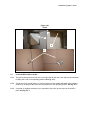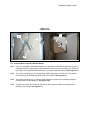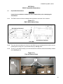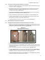
1
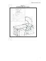
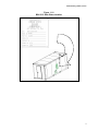
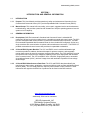
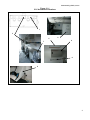
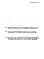
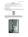
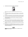
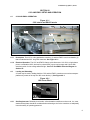
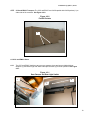
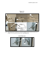
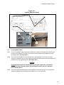
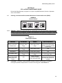
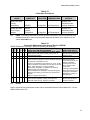
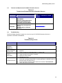
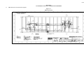
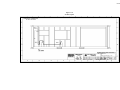
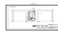
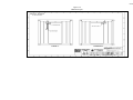
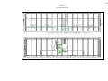
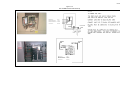
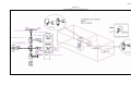
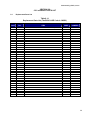
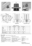
Field Pack-Up (FPU®) Series
USER MANUAL FOR
CCC
CONTAINERIZED COMMAND CENTER
EWCC
EXPANDABLE WALL COMMAND CENTER
User and General Purpose
Maintenance Manual
FPU® SERIES
PART NUMBER
NSN
CONTAINERIZED COMMAND CENTER (TAN)
CCC208-T
8145-01-502-3930
CONTAINERIZED COMMAND CENTER (GREEN)
CCC208-G
8145-01-502-3930
FPU® SERIES
PART NUMBER
NSN
EXPANDABLE WALL COMMAND CENTER (TAN)
EWCC208-T
8145-01-502-3927
EXPANDABLE WALL COMMAND CENTER (GREEN)
EWCC208-G
8145-01-502-3927
Version 001A, 11 Nov 2005
T
BOH Environmental, LLC
FPU Mobility Systems Division
4116C Walney Road, Chantilly, VA 20151
Ph: (703) 449-6020 Fax: (703) 449-6022
THIS PAGE INTENTIONALLY LEFT BLANK
Field Pack-Up (FPU®) Series
Figure 1.1-1
BOH EWCC Data Plates Location
i
Field Pack-Up (FPU®) Series
Figure 1.1-2
BOH CCC Data Plates Location
ii
Field Pack-Up (FPU®) Series
TABLE OF CONTENTS
Section ................................................ Page
Section................................................ Page
DATA PLATES.................................................... i
TABLE OF CONTENTS .................................... iii
LIST OF ILLUSTRATIONS ............................... iv
LIST OF TABLES.............................................. iv
SAFETY SUMMARY.......................................... v
WARNING SUMMARY .................................... vii
V. EWCC EXPANDABLE WORK-STATIONS
5.1 Expandable Work-Stations.................. 18
5.2 EWCC Work-Station Preparation for
Shipment............................................. 19
I.
INTRODUCTION AND
GENERAL INFORMATION
1.1 Introduction ............................................1
1.2 General Information...............................1
1.3 Special Tools & Test Equipment ...........2
II. CCC and EWCC COMPONENTS AND
ACCESSORIES
2.1 CCC Components & Accessories..........3
2.2 EWCC Components & Accessories ......5
III. CCC and EWCC PREPARATION FOR
USE, STORAGE, MOVEMENT AND
SHIPMENT
3.1 Preparation for Use ...............................7
3.2 Preparation for Storage, Shipment, and
Movement ....................................................8
IV. CCC and EWCC SETUP AND
OPERATIONS
4.1 CCC and EWCC Operation ...................9
4.2 Loading and Unloading..........................9
4.3 CCC and EWCC Doors ......................10
4.4 EWCC Doors and Floor Plan...............13
4.5 Red and White Light Conditions ..........13
4.6 CCC and EWCC HVAC.......................14
4.7 CCC and EWCC HVAC Latches .........15
4.8 CCC and EWC Computer Monitor
Mounts ................................................16
4.9 Exterior Electrical Connections............17
VI. CCC and EWCC MAINTENANCE GUIDE
6.1 Cleaning, Lubrication and Preventative
Maintenance Checks and Services
(PMCS) ............................................... 20
6.2 Lubrication........................................... 20
6.3 PMCS .................................................. 21
6.4 Repairs ................................................ 21
6.5 Technical and Replacement Part Web
Information Sources............................ 22
6.6 Troubleshooting................................... 22
VII. CCC and EWCC ELECTRICAL
COMMUNICATION DIAGRAMS
7.1 EWCC Electrical and Communication
Diagrams............................................. 23
VIII. CCC and EWCC PARTS LISTS
8.1 Replacement Parts List....................... 30
IX WARRANTY ...................................
31
iii
Field Pack-Up (FPU®) Series
LIST OF ILLUSTRATIONS
Figure .................................................. Page
Figure.................................................. Page
Figure 1.1-1 BOH EWCC Data Plates Location.. i
Figure 1.1-2 BOH CCC Data Plates Location.... ii
Figure 2.1-1 CCC Accessories Locations ..........4
Figure 2.2-1 EWCC Accessories Locations.......6
Figure 3.1-1 EWCC and CC Grounding Rod .....7
Figure 4.1-1 CCC Interior and EWCC Interior ...9
Figure 4.2-1 ISO Corner Block...........................9
Figure 4.2-2 Forklift Pockets ............................10
Figure 4.3-1 Door Damper and Door Light
Switch ........................................................10
Figure 4.3-2 CCC Floor Plan............................11
Figure 4.3-3 Locks and Seals ..........................12
Figure 4.3-4 Interior Door Locks ......................12
Figure 4.4-1 Retracted EWCC Workstation
Floor Plan ..................................................13
Figure 4.5-1 Lighting Switch Locations ............14
Figure 4.6-1 HVAC........................................... 15
Figure 4.7-1 HVAC Latches............................. 16
Figure 4.8-1 CCC and EWCC Monitor Mounts 17
Figure 5.1-1 EWCC Workstation Setup ........... 18
Figure 5.1-2 Pins and Ratchet Straps.............. 18
Figure 5.2-1 Retracting Workstations .............. 19
Figure 7.1-1 EWCC Top Layout ...................... 23
Figure 7.1-2 AC Side Layout ........................... 24
Figure 7.1-3 EWCC Load Center Layout......... 25
Figure 7.1-4 EWCC End Layout ...................... 26
Figure 7.1-5 CCC Load Center Layout............ 27
Figure 7.1-6 CCC and EWCC Power Phase
Hook-Up .................................................... 28
Figure 7.1-7 EWCC & CCC Communications
Layout........................................................ 29
LIST OF TABLES
Table.................................................... Page
Table ................................................... Page
Table 6.1-1 Cleaning Procedures ....................20
Table 6.2-1 Lubrication ....................................21
Table 6.3-1 Preventative Maintenance Checks
and Services (PMCS) ................................21
Table 6.5-1 Technical and Replacement Part
Information Sources .................................. 22
Table 6.6-1 Troubleshooting Checks............... 22
Table 8.1-1 Replacement Parts List ................ 30
iv
Field Pack-Up (FPU®) Series
SAFETY SUMMARY
This warning summary contains general safety precautions and hazardous material warnings that must be
understood and applied during operation and maintenance of this equipment. Failure to observe these
warnings could result in serious injury or death.
GENERAL WARNINGS
HEAVY PARTS - heavy object on human figure shows that heavy parts present
a danger to life or limb.
HEAVY PARTS - heavy object pinning human figure against wall shows that
heavy, moving parts present a danger to life or limb.
HEAVY PARTS - hand with heavy object on top shows that heavy parts can
crush and harm.
HEAVY PARTS - foot with heavy object on top shows that heavy parts can crush
and harm.
SLICK FLOOR - wavy line on floor with legs prone shows that slick floor
presents a danger for slipping or falling.
HEAVY OBJECT - human figure stooping over heavy object shows physical
injury potential from improper lifting technique.
ELECTRICAL - electrical wire to arm with electricity symbol running through
human body shows that shock hazard is present.
ELECTRICAL - electrical wire to hand with electricity symbol running through
hand shows that shock hazard is present.
v
Field Pack-Up (FPU®) Series
CRYOGENIC - hand in block of ice shows that the material is extremely cold and
can injure human skin or tissue.
FIRE - flame shows that a material may ignite and cause burns.
VAPOR - human figure in a cloud shows that material vapors present a danger to
life or health.
CHEMICAL - drops of liquid on hand shows that the material will cause burns or
irritation to human skin or tissue.
EYE PROTECTION - person with goggles shows that the material will injure the
eyes.
vi
Field Pack-Up (FPU®) Series
WARNING SUMMARY
This warning summary contains general safety warnings and hazardous material warnings that
must be understood and applied during operation and maintenance of this equipment. Failure to
observe these precautions could result in serious injury or death to persons using equipment.
WARNING
Do not allow the system to swing if using an overhead lift. Always insure an
appropriate sling is used in the lift. Always use properly sized forklift, crane, or
lifting device. Failure to comply could cause injury to personnel or damage to the
equipment.
WARNING
Standard forklift principles apply when working with or on the CCC & EWCC.
When working with ground guides during the loading or unloading of a module,
never move the CCC & EWCC onto the transport vehicle while the ground guide
is between the forks, transport vehicle, and the CCC container. Serious injury
could occur if the ground guide is pinned between the forklift and the CCC
container. Forklift operators must maintain visual contact with their ground
guides at all time.
Always follow standard forklift procedures. A tilt hazard exists when forklift
operators try to lift a CCC & EWCC container with the forks not completely
inserted. Always lift a CCC & EWCC container with the forks completely seated
and the fork frame against the CCC & EWCC container. This places the heavier
part of the load back into the tines versus out on the tips. A tilt situation exists
when the heaviest part of the load is out on the tips of the tines, on uneven
ground, with forks fully extended, and while traveling. Operators should always
keep loads low and close to the forklift carriage. Operators should never travel
when the load is in the fork’s extended position.
WARNING
The CCC contents are heavy and could cause injury if they fall onto or strike
personnel. As a rule, always insure that equipment, i.e. monitors, computers,
printers etc. are secured with the straps provided. The CCC workstations are
heavy, but roll easily; seek assistance when deploying the workstation to
operating position. Never store or transport equipment that is not part of the
function or mission of the CCC & EWCC.
WARNING
Fall hazards exist when climbing onto or working from the top of the container.
Always maintain three points of contact when climbing onto the CCC & EWCC
container. Never move, step, or walk backwards when working on top of the
system. All movement should be in the forward direction. A fall can occur if
personnel lose concentration and step backwards off of the edge. Stand erect
only if necessary and only away from the edge. Working from a kneeling position
helps reduce the threat of a fall.
The CCC & EWCC interior floor and rooftop will encounter mud, snow, ice,
rainwater, and other potentially slippery substances. Keeping the inside floor of
the containers clean is important; nevertheless, when these conditions exist
always move with caution inside CCC & EWCC containers. Failure to maintain
cleanliness could cause a slip and injury.
vii
Field Pack-Up (FPU®) Series
WARNING
The EWCC equipment can be heavy and awkward to handle by a single person.
This is especially true of the larger components, i.e. rollout workstations. The
movement and adjustment of these items is a two-person operation.
WARNING
Overhead power lines and obstructions can cause serious injury or damage to
property. Forklift operators, truck drivers, and ground guides should always clear
overhead when loading, unloading, or moving the CCC & EWCC containers.
WARNING
To prevent electrical shock hazard, only trained and qualified personnel should
attempt to correct electrical discrepancies. Additionally, electrical power must be
disconnected before any electrical system work is performed.
WARNING
Protective gloves should be worn when handling metal parts in below freezing
temperatures. Failure to wear gloves may result in skin freezing to the metal
upon contact and cause tearing of the flesh when attempting to pull away from
the metal.
WARNING
Dry cleaning solvent is flammable and cannot be used near an open flame. Use
only in well-ventilated places and have a fire extinguisher available. Use of
protective clothing as directed in the product MSDS is required. Failure to
comply could result in injury to personnel or equipment damage. Do not allow
cleaning solvents or compounds to come in contact with door seals, covers,
fabric, or rubber components. Damage to these components will occur.
viii
SECTION I
INTRODUCTION AND GENERAL INFORMATION
THIS PAGE INTENTIONALLY LEFT BLANK
Field Pack-Up (FPU®) Series
SECTION I
INTRODUCTION AND GENERAL INFORMATION
1.1
INTRODUCTION
1.1.1
Purpose. This User Manual provides operational, safety and maintenance information for the
Containerized Command Center (CCC) and the Expandable Wall Command Center (EWCC).
1.1.2
Manual Scope. This manual will cover safety, minor repair, suggested service and maintenance,
troubleshooting, and provides a parts list with illustrations to help the operating personnel use the
system to its full capacity.
1.2
GENERAL INFORMATION
1.2.1
Descriptions. BOH Environmental’s Containerized Command Center is a durable ISO
configured, 20-foot long single container that is a portable command and control center. The CCC
has four workstations with communication via phone and Intranet/Internet connection. The BOH
Environmental Expandable Wall Command Center is also a durable ISO configured, 20 foot long
single container with communication via phone and Intranet/Internet connection. The EWCC is a
portable command and control center that provides six expandable workstations.
1.2.2
CCC and EWCC System Benefits. The CCC and EWCC are air-conditioned/heated single
rooms that provide file cabinets, shelves with straps for printers, scanners, and retractable
monitor base mounts for securing computer monitors during transit. The CCC and EWCC provide
the operators with a rapid set-up or takedown capability for the quick deployment and relocation
of the command center. The CCC and EWCC have 110v60Hz, single phase power, retractable
air-conditioner/heater (HVAC), and two 2-stage doors with automatic trip-switch for low-voltage
white/red light.
1.2.3
CCC and EWCC Manufacturer’s Data Plate. The CCC and EWCC data plates identify the
manufacturer’s part number, serialization, contract and delivery order number and National Stock
Number (NSN). The CCC data plates are unique by serial number to each container. Further
information with regard to the BOH line of products can be found on the BOH web site.
www.bohenvironmental.com
Additionally, BOH can be reached at:
BOH Environmental, LLC
FPU Mobility Systems Division
4116C Walney Road, Chantilly, VA 20151
Ph: (703) 449-6020 Fax: (703) 449-6022
1
Field Pack-Up (FPU®) Series
1.3
SPECIAL TOOLS AND TEST EQUIPMENT
1.3.1
Descriptions. A General Mechanics Tool Set (NSN 5180-01-454-3787) is sufficient to perform
minor repairs on the containers and modules.
Note: All hardware is standard thread and removed with a Counterclockwise rotation and
tightened with a Clockwise rotation.
WARNING
Personnel performing electrical repairs and service should be certified electricians and
have the proper tools and test equipment.
Field Pack-Up (FPU®) Series
SECTION II
CCC and EWCC COMPONENTS AND ACCESSORIES
Field Pack-Up (FPU®) Series
THIS PAGE INTENTIONALLY LEFT BLANK
Field Pack-Up (FPU®) Series
SECTION II
CCC and EWCC Components and Accessories
This section 2.1 describes the following components:
FPU® SERIES
PART NUMBER
NSN
CONTAINERIZED COMMAND CENTER (TAN)
CCC208-T
8145-01-502-3930
CONTAINERIZED COMMAND CENTER (GREEN)
CCC208-G
8145-01-502-3930
2.1
CCC COMPONENTS & ACCESSORIES
2.1.1
Description. The system consists of the BOH Environmental Containerized Command Center
(CCC) that has four workstations for communication via phone and Intranet/Internet connection.
2.1.2
The CCC is provided with two entry doors and four desk workstations with a continuous top (1).
Each workstation has two lockable file cabinets with four drawers (2). See Figure 2.1-1.
2.1.3
The CCC has a centrally located retractable heater/air-conditioner (HVAC) (3), wall mounted file
cabinets (4) with latch type doors, wall mounted shelves for securing equipment, i.e. printers,
scanners, etc. and overhead white and red condition lights (5). See Figure 2.1-1.
2.1.4
Each CCC work station is provided with a wall mounted surge protected power strip (6), an
adjustable roller chair (7) and retractable computer monitor base mount (8) that are easily
retracted below the desktop with straps to secure the monitor while in transit. See Figure 2.1-1.
Field Pack-Up (FPU®) Series
Figure 2.1-1
CCC Accessories Locations
1
3
5
7
2
4
6
8
4
Field Pack-Up (FPU®) Series
This section 2.2 describes the following components:
FPU® SERIES
PART NUMBER
NSN
EXPANDABLE WALL COMMAND CENTER (TAN)
EWCC208-T
8145-01-502-3927
EXPANDABLE WALL COMMAND CENTER (GREEN)
EWCC208-G
8145-01-502-3927
2.2
EWCC COMPONENTS & ACCESSORIES
2.2.1
Description. The system consists of the BOH Environmental Expandable Wall Command Center
(EWCC) — a durable ISO configured, 20’ x 8’ single container that is a command and control
center. The EWCC has 6 workstations for communication via phone and Intranet/Internet
connection.
2.2.2
The EWCC is provided with a main door (1), a secondary entry door (2), and three roll out
workstation platforms (3) to provide six retractable desk workstations (4) See Figure 2.2-1.
2.2.3
The EWCC has a retractable heater/air-conditioner (HVAC) (5), overhead wall mounted file
cabinets (6) with latch type doors, wall mounted shelves for securing equipment, i.e. printers,
scanners, etc. and overhead white and red condition lights (7). See Figure 2.2-1.
2.2.4
Each EWCC work station is provided a wall mounted surge protected outlet GFCI, an adjustable
chair (8) fixed to the floor and computer monitor base mounts (9) that are easily retracted below
the desktop with straps to secure the monitor while in transit and storage. See Figure 2.2-1.
Field Pack-Up (FPU®) Series
Figure 2.2-1
EWCC Accessories Locations
3
1
2
4
5
7
6
8
9
6
Field Pack-Up (FPU®) Series
SECTION III
CCC and EWCC
PREPARATION FOR USE, STORAGE, MOVEMENT AND SHIPMENT
Field Pack-Up (FPU®) Series
THIS PAGE INTENTIONALLY LEFT BLANK
Field Pack-Up (FPU®) Series
Section III
CCC and EWCC
Preparation for Use, Storage, Movement, and Shipment
NOTE: Review the Safety Summary prior to any MHE Movement, Service or
Operation of the CCC and EWCC on Pages iv through vii.
NOTE: Consult the Container manufacturer’s Data Plate for Maximum Gross Weight
for each type of container.
3.1
PREPARATION FOR USE
3.1.1
Site Requirements. Relatively level terrain, soil and weather conditions such as mud, ice,
snow, sand and flood plane should be considered when selecting a site for the containers to
insure safety of operating personnel.
WARNING
Electrical Considerations. The supporting electrical extension cords or
generator should be grounded properly with Grounding Rod assembly (1)
mounted on the interior wall near the communication panels prior to making
electrical connection to the CCC and EWCC. See Electrical Diagrams in Section
VII. See Figure 3.1-1.
Figure 3.1-1
EWCC and CCC Grounding Rod
1
7
Field Pack-Up (FPU®) Series
3.2
PREPARATION FOR STORAGE, SHIPMENT AND MOVEMENT
WARNING
A ground guide should always be in view when moving or positioning the CCC and
EWCC.
3.2.1
The retractable workstations for the EWCC and all other equipment, i.e. HVAC for both the
CCC and EWCC should be fully retracted and properly secured prior to storage, shipment or
movement.
3.2.2
In preparation for storage, shipment or movement, standard practice is that all loose material
should be removed and general cleaning and inspection of the interior should be performed.
3.2.3
All locking devices, shelves, drawer latches and door edges should be swept or wiped clean
of debris and inspected to insure they function prior to securing the CCC and EWCC.
See Cleaning Table 6.1-1.
3.2.4
Lubrication of all moving parts, devices, locks, latches, and hinges should be performed.
NOTE: Lubrication and cleaning of the CCC and EWCC moving parts is recommended prior
to long-term storage or shipment. See Cleaning and Lubrication Tables 6.1-1 and 6.2-1.
3.2.5
All shelves, chairs, equipment, i.e. monitors, printers, and HVAC units should be locked in
place and secured with straps, pins and locking devices that are provided, prior to closing the
container.
3.2.6
Do’s and Don’ts for CCC and EWCC Transport. When transporting the CCC and EWCC to
another location via truck, flatbed, or FPU Transport System (FPU-TS), the CCC and EWCC
should be properly secured to that transport platform to prevent stress damage to the CCC
and EWCC during transportation.
CAUTION
Do not transport or store material that is not part of, or intended for, the CCC
and EWCC function or mission.
Field Pack-Up (FPU®) Series
SECTION IV
CCC and EWCC SETUP AND OPERATIONS
Field Pack-Up (FPU®) Series
THIS PAGE INTENTIONALLY LEFT BLANK
Field Pack-Up (FPU®) Series
SECTION IV
CCC AND EWCC SETUP AND OPERATION
4.1
CCC AND EWCC OPERATION
Figure 4.1-1
CCC Interior and EWCC Interior
1
2
4.1.1
Description. The CCC is a four-workstation container (1) and the EWCC is a six workstation (2)
that are stand-alone 20 ft. long FPU containers. See Figure 4.1-1.
4.1.2
Electrical Operation. The CCC and EWCC feature quick-disconnect 110v 60 Hz, single-phase
power, a retractable HVAC, shelves for printers/CPU, pop-up monitor trays and 2 doors with
automatic switch for low-voltage white/red light. See CCC and EWCC Electrical Diagram in
Section VII.
4.2
Loading and Unloading
A Crane may be used in loading both the CCC and the EWCC containers onto various transport
platforms by means of the top four ISO corner blocks (1). See Figure 4.2-1.
Figure 4.2-1
ISO Corner Block
1
4.2.1
Site Requirements. Relatively level terrain, soil and weather conditions such as mud, ice, snow,
sand and flood plane should be considered when selecting a site for the containers to adequately
insure the safety of operating personnel.
9
Field Pack-Up (FPU®) Series
4.2.2
CCC and EWCC Transport. The CCC and EWCC are forklift-capable with forklift pockets (1) on
either side of the container. See Figure 4.2-2.
Figure 4.2-2
Forklift Pockets
1
4.3 CCC and EWCC Doors
4.3.1
The CCC and EWCC both have two common entrance doors and are provided with door
dampers (1) and interior light red/ white interrupter switches (2) for door operation. See Figure
4.3-1.
Figure 4.3-1
Door Damper and Door Light Switch
1
2
10
Field Pack-Up (FPU®) Series
4.3.2
The CCC and EWCC have a main entrance door (1) and a secondary access door (2). The main
entrance door is located (when facing the door) with the electrical and communication hookups
(3) on the right side of the container and the retractable heater/air conditioner (HVAC) (4) on the
center left side of the container. Light switches (5) are located on the interior right side of the main
door (1). See Figure 4.3-2
Figure 4.3-2
CCC Floor Plan
4
2
1
5
3
4.3.3
Door locks The CCC and EWCC have a robust lock system that consists of a large handle with a
key (1) and piston (2). When engaged, the piston (2) provides a positive locked position (3) to
secure the door handle. A door handle instruction plate (4) is provided on the door.
See Figure 4.3-3.
4.3.4
The door handle operation is as follows:
1. To engage the interior door lock-blade (6), swing the exterior handle (5) downward then
return it to the center position; at this point the door may be key locked. See Figure 4.3-3.
2. To open the door and disengage the interior lock-blade (6), swing the handle (5) to the
upward OPEN position and return to center position. See Figure 4.3-3.
NOTE: Ensure the door is in the unlocked position before attempting to open or close.
Field Pack-Up (FPU®) Series
Figure 4.3-3
Door lock
3
1
2
5
4
4.3.5
6
Interior Door Lock. The MWC door mechanism is design to allow exit while the exterior lock is
engaged. Pull door handle (2) upward to open. See Figure 4.3-4.
FIGURE 4.3-4
Interior Door Lock
1
2
Field Pack-Up (FPU®) Series
4.4
EWCC Doors and Floor Plan
4.4.1
The EWCC has a main entrance (1) and a secondary access door (2). The main entrance door is
located (when facing the door) with the electrical hookups (3) on the right side of the container
and the retractable heater/air conditioner (HVAC) (4) and window (5) on the left side of the
container. Light switches (6) are located on the interior right side of the main door (1).
See Figure 4.4-1.
Figure 4.4-1
Retracted EWCC Work-Station Floor Plan
4
5
2
1
6
3
4.5
Red and White Lighting conditions
4.5.1
The EWCC and CCC are provided a bank of two switches, just inside the main entrance door.
See Fig. 4.3-2 (5) and 4.4-1 (6).
4.5.2
They are used to set the red/white lighting conditions.
4.5.3
The left switch (1) sequence is as follows: See Fig. 4.5-1.
1.
2.
3.
4.5.4
1.
2.
3.
The left switch in the Up-position will select Door switch Activated. That enables the door
switches to interrupt white light from escaping when the door is opened and switch to red
light.
When in the Center-position the lighting is off.
When in the Down-position the light selection red is continuous.
The right switch (2) sequence is as follows: See Fig. 4.5-1.
The right switch is used to select white or red lighting.
In the Up position the white lighting is selected.
In the Down position the red lighting is selected.
NOTE: The door switches will not permit the white lights to stay on when the doors are opened in
both the red or white condition.
13
Field Pack-Up (FPU®) Series
Figure 4.5-1
Lighting Switch Locations
1
2
3
4.6
CCC and EWCC HVAC
4.6.1
The CCC and EWCC are provided with a Heater/Air-conditioner unit (HVAC) (4) located on the
left side of the container. The HVAC is mounted on drawer slides for easy deployment to the
operating position. See Figure 4.4-1.
4.6.2
The HVAC has a weather cover and exterior door (2) with latches to cover the unit during
shipment or storage. This door must first be unlatched (3) to allow the HVAC to be unlocked and
pushed out into the operating position. See Figure 4.6-1.
CAUTON
Do not attempt to operate the HVAC without opening the shutter door and pushing
out the unit to the operating position. Overheating will result if the unit is operated
in the stowed position.
4.6.3
The HVAC can be retracted within the CCC and EWCC with latch devices for securing during
storage and shipment and unlatched to be pushed out for HVAC operation.
14
Field Pack-Up (FPU®) Series
Figure 4.6-1
HVAC
1
2
3
4.7
CCC and EWCC HVAC Latches
4.7.1
The locking devices for the HVAC are on the right and left side of the unit and must be unlatched
to deploy the HVAC to the operating position. See Fig. 4.7-1.
4.7.2
The latches in the locked position (1) must be pulled out and rotated downward to the released
position (2). At this point the HVAC can be pushed out to the operating position. See Fig. 4.7-1.
4.7.3
A lock bar (3) engages a bracket (4) on each side of the HVAC to securely lock the HVAC in
place. See Fig. 4.7-1.
Field Pack-Up (FPU®) Series
Figure 4.7-1
HVAC Latches
2
1
4
3
4.8 CCC and EWCC Computer Monitor Mounts
4.8.1
Each CCC and EWCC workstation desktop (1) is provided a retractable keyboard tray (2) and a
retractable monitor-mounting tray (3) that holds the computer monitor with straps (4). This allows
the monitor to be retracted below the desktop (1) during storage and shipment. See Figure 4.8-1.
4.8.2
The monitor-mounting tray (3) is supported by flexible springs (5) on either side of the monitormounting tray (3) that allows easy positioning of the monitor. See Figure 4.8-1.
4.8.3
The monitor-mounting tray (3), from the stowed position, is raised to the operating position by
pushing forward on the springs (5). See Figure 4.8-1.
4.8.4
To lower the monitor, pull forward on the springs (5) to allow the monitor to retract below the
desktop (1) for storage. See Figure 4.8-1.
Field Pack-Up (FPU®) Series
Figure 4.8-1
CCC and EWCC Monitor Mounts
1
2
Storage
Position
3
4
5
Operation
Position
4.9 Exterior Electrical Connections
4.9.1
The EWCC/CCC is provided with an external cable (2) connection to an external generator for
240VAC supply. The EWCC/CCC is 110VAC, 60Hz, Single Phase. See Figure 7.1-6.
4.9.3.1 Connect wires as follows:
Black wire - shore power line 1
Red wire - shore power line 2
White wire - shore power neutral
Green wire - shore power ground
NOTE: This is standard residential coloring. A generator should have outputs labeled as L1, L2,
N, G or by color or both.
4.9.4
The cables are housed within a protective compartment on one side of the container marker
“Shore Power Connection”.
NOTE: The 240VAC wire ends are (bare wire) open ends with no connectors so the user may
determine the type and style of connection required to a source such as a generator or 240VAC
power source.
17
Field Pack-Up (FPU®) Series
THIS PAGE INTENTIONALLY LEFT BLANK
Field Pack-Up (FPU®) Series
SECTION V
EWCC EXPANDABLE WORKSTATIONS
Field Pack-Up (FPU®) Series
THIS PAGE INTENTIONALLY LEFT BLANK
Field Pack-Up (FPU®) Series
SECTION V
EWCC Expandable Workstations
5.1
Expandable Workstations
CAUTION
Insure the area outside the container is clear of obstructions prior to deploying the
workstations.
5.1.1
The EWCC has three rollout workstations that expand the work area of the container.
Figure 5.1-1
EWCC Work-Station Setup
A
2
Workstations Retracted
A
1
C
B
C
B
Workstations Deployed
TOP VIEW
5.1.2
There are three workstations A, B and C in the EWCC that can be deployed with relative ease by
releasing the securing pins (1) and ratchet straps (2). See Fig. 5.1-1.
5.1.3
The pins (1) and ratchet straps (2) must be accessed from both the main and secondary entrance
doors. See Fig. 5.1-2.
Figure 5.1-2
Pins and Ratchet Straps
2
1
C
A
B
18
Field Pack-Up (FPU®) Series
5.1.4
The sequence for deploying the workstations is as follows:
1. Remove the workstation retention pins located outside the container (3) and attached to each
side of the workstation. See Fig. 5.2-1.
2. After electrical power, ground connection and lighting has been established, two personnel
should enter the container, one from the main entrance door (1) and the other from the
secondary entrance door (2). See Fig. 5.1-1.
3. At this point the ratchet straps (2) and pins (1) from both workstations may now be removed
and workstations A and B may be deployed. See Fig. 5.1-2.
4. Secure the workstations A and B with pins (1) to prevent their movement. See Fig. 5.1-2.
5. Proceed to third workstation C next to the main entrance door and remove the pins (1) and
ratchet straps (2) and deploy the workstation. See Fig. 5.1-2.
6. Secure the workstation C with pins (1) to prevent its movement. See Fig. 5.1-2.
5.2
EWCC WorkStation Preparation for Shipment
5.2.1
Retracting and securing sequence for the three workstations is as follows:
1. Remove the securing pins from workstation A with assistance from other personnel from the
exterior of the container, push the workstation (1) until fully retracted and the hand holds (2)
are together and outer seal (3) makes good contact. See Fig. 5.2-1.
Figure 5.2-1
Retracting the Work-Stations
1
2
3
2. Secure the workstation with the pins (1) and ratchet straps (2). See Fig. 5.1-2.
3. Remove the securing pins (3) from workstation B with assistance from other personnel from
the exterior of the container, push the workstation until fully retracted and the outer seal
makes good contact.
4. Secure the workstation with the pins (1) and ratchet straps (2). See Figure 5.1-2.
5. Proceed to third workstation C next to the main entrance door and remove the securing pins
(1) with assistance from other personnel from the exterior of the container, push the
workstation (1) until fully retracted and the outer seal (3) makes good contact.
6. Secure the workstation with the pins (1) and ratchet straps (2). See Figure 5.1.2. Re-attach
Workstation retention pins located outside the container.
19
Field Pack-Up (FPU®) Series
SECTION VI
CCC AND EWCC MAINTENANCE GUIDE
Field Pack-Up (FPU®) Series
THIS PAGE INTENTIONALLY LEFT BLANK
Field Pack-Up (FPU®) Series
SECTION VI
CCC and EWCC MAINTENANCE GUIDE
Review the Safety Summary on pages iv to vii prior to any MHE Movement, Service or Operation
of the CCC & EWCC.
6.1
Cleaning, Lubrication and Preventative Maintenance Checks and Services (PMCS)
WARNING
Chemical Hazard
6.1.1
Cleaning. Cleaning is performed after an operational event and periodically if stored/ staged
outside to insure the containers, modules and accessories will perform as designed. Cleaning
also assists in the performance of maintenance and insures the good operating condition of
the CCC & EWCC. See Table 6.1-1.
Table 6.1-1
Cleaning Procedures
SURFACE
OIL/GREASE
SALT/MUD/DIRT/
DEBRIS
Exterior and Interior
Surfaces (All)
Detergent, Water,
Rags
Soapy Water, Brush,
Rags
Fabric safety straps
Detergent, Water,
Rags
Soapy Water, Brush
N/A
Storage box seals
and gaskets
Damp and Dry Rags
Damp and Dry Rags
N/A
CCC EWCC Floor
Detergent, Water,
Rags
Soapy Water, Brush,
Rags
EWCC Door Hinges,
Drawer/Shelf Glides,
Rollers and Floor
Tracks
N/A
Brush, Rag and
lubricate as needed to
ensure rails travel freely
Dry Rags, Coat with Lube
Oil or Spot Paint
Corrosion Removal
Compound and Wire Brush,
Dry Rags and Lubricate as
needed
6.2
RUST/CORROSION
Corrosion Removal
Compound and Wire Brush,
Dry Rag, Coat with Lube Oil
or Spot Paint
Lubrication. Lubrication is performed after cleaning, periodic events and prior to storage to
insure good operation and prevention of corrosion of moving parts. See Table 6.2-1.
20
Field Pack-Up (FPU®) Series
Table 6.2-1
Lubrication Procedures
FLUID
LUBRICANT
USAGE
Drawer/Shelf
Slides, Pins, Floor
Locking
Mechanisms
OE/HDO
Lubricating Oil,
General
Purpose
Preservative
Storage Box Door
Locks, hinges,
Handles
6.3
CAPACITIES
As Required
As Required
EXPECTED
TEMPERATURES
INTERVAL
All Temperatures
Monthly or as
Required if under
Adverse Situations
All Temperatures
Monthly or as
Required if under
Adverse Situations
PMCS. Preventative Maintenance Checks and Services (PMCS) should be performed at the
established periods in order to insure smooth and proper operation of the equipment in the
system. See Table 6.3-1.
Table 6.3-1
Preventive Maintenance Checks and Services (PMCS)
PMCS B (Before) D (During) A (After) W (Weekly) M (Monthly)
#
B
D
A
1
*
*
*
W M
*
2
*
3
*
6.4
*
*
INSPECTION ITEM AND PROCEDURE
Storage Boxes, Roll out Workstations, Walls, EWCC
Check all doors and walls for cracks, dents, holes, or
loose/missing hardware.
Lubricate hinges, locks floor rails as required.
Exterior
Check all exterior surfaces for cracks and dents that effect
the operation of the EWCC & CCC.
Check for accumulations of dirt, debris, ice, snow, or salt.
Clean as required. Check EWCC & CCC floor for dirt and
debris. Clean with broom or rags as required.
Check EWCC workstation Lock devices for cracks or
missing latches, pins and lanyards.
Check workstation for damaged or missing locking jackstraps and for missing or loose lock pins, linchpins and
lanyards.
Replace or tighten as necessary.
Data Plates
Check plates for legibility, damage and/or absence.
Clean with water and rag. Replace as needed.
EQUIPMENT NOT
READY/AVAILABLE IF
Missing doors, punctures,
damage that would cause
hazard or injury.
Damage that would
cause malfunction of the
EWCC workstation
systems such as lockdown devices would
cause injury.
Missing or damaged pins
would cause injury by not
securing the workstation.
Replace any missing or
damaged pins.
Missing data will impair
maritime shipment.
Repairs
Repair, adjustment and replacement of parts can be accomplished with a General Mechanic’s Tool set
(NSN 5180-01-454-3787).
21
Field Pack-Up (FPU®) Series
6.5
Technical and Replacement Part Web Information Sources
Table 6.5-1
Technical and Replacement Part Information Sources
FUNCTION
HVAC
BODY REPAIR
& WELDING
6.6
TECH MAUNEL & TITLE
TWINTEMP MODEL EM18J34B TECH
WEB LIBRARY
FRIEDRICH OPERATING GUIDE &
INSTALLATION INSTRUCTION
LOCATED IN THE FILE CABINET
TM9-237
Welding Theory and Application
TM9-510
Metal Body Repair and Related
Operation
MFG.
WEB SITE / ADDRESS & PHONE
NUMBER
HTTP/WWW.FRIEDRICH.COM/PDF/
WWW.LOGSA.COM
WWW.TRAINARMY.MIL
Troubleshooting
Review the Safety Summary on pages iv to vii prior to any CCC & EWCC Movement, Service or
Operation of the EWCC Workstations.
Table 6.6-1
Troubleshooting Checks
FUNCTION
CHECKS
CCC & EWCC
Operation
Section 4.3
EWCC Workstation
will not roll out
HVAC is
Overheating
No Electrical Power
1. Insure that the material stored inside is not obstructing the floor rollers
operation.
2. Check for exterior ground obstructions, i.e. rocks or dirt.
1. Insure the weather cover has been removed.
2. Inspect the filter and replace if necessary.
3. Inspect the Freon charge.
4. Recharge the Freon.
1. Insure that the external electrical power source or generator is properly
connected, operating and grounded, i.e. power generator or extension cord to a
domestic facility AC power source.
2. Insure the power connection cables make firm connection. See Section VII.
3. Check and reset circuit breakers.
22
Field Pack-Up (FPU®) Series
THIS PAGE INTENTIONALLY LEFT BLANK
Field Pack-Up (FPU®) Series
SECTION VII
CCC and EWCC ELECTRICAL COMMUNICATION DIAGRAMS
THIS PAGE INTENTIONALLY LEFT BLANK
Field Pack-Up (FPU®) Series
SECTION VII
CCC AND EWCC ELECTRICAL COMMUNICATION DIAGRAMS
7.1
EWCC Electrical and Communication Diagrams
Figure 7.1-1
EWCC Top Layout
23
Field Pack-Up (FPU®) Series
Field Pack-Up (FPU®) Series
Figure 7.1-2
AC Side Layout
24
Field Pack-Up (FPU®) Series
Field Pack-Up (FPU®) Series
Figure 7.1-3
EWCC Load Center Layout
25
Field Pack-Up (FPU®) Series
Field Pack-Up (FPU®) Series
Figure 7.1-4
EWCC End Layout
26
Field Pack-Up (FPU®) Series
Field Pack-Up (FPU®) Series
Figure 7.1-5
CCC Load Center Layout
27
Field Pack-Up (FPU®) Series
Field Pack-Up (FPU®) Series
Figure 7.1-6
CCC and EWCC Power Phase Hook-Up
Black Wire
Lien 1
Black & Red Wire
Line 2
Black & White Wire Neutral
Green Wire
Ground
Ground Rod
Black Wire
Line 1
Black & Red Wire
Line 2
Black & White Wire Neutral
Green Wire
Ground
28
Field Pack-Up (FPU®) Series
Field Pack-Up (FPU®) Series
Figure 7.1-7
CCC and EWCC Communications Layout
29
SECTION VIII
CCC and EWCC PARTS LISTS
THIS PAGE INTENTIONALLY LEFT BLANK
Field Pack-Up (FPU®) Series
SECTION VIII
CCC and EWCC PARTS LIST
8.1
Replacement Parts List
Table 8.1-1
Replacement Parts List (The BOH CAGE Code is 1NSG3)
PAGE
FIG.
ITEM
EWCC & CCC HVAC Model EM18 Twin Temp
CAGE
89338
PART
NUMBER
EM18J34B
30
THIS PAGE INTENTIONALLY LEFT BLANK
SECTION IX
CCC and EWCC WARRANTY
Field Pack-Up (FPU®) Series
THIS PAGE INTENTIONALLY LEFT BLANK
Field Pack-Up (FPU®) Series
Boh Environmental, L.L.C
MANUFACTURER’S LIMITED WARRANTY TERMS
Boh Environmental, LLC (BOH) warrants that the Products, including the Field Pack-Up
(FPU) Systems and other Containerized Mission Systems it manufactures, shall be free from
defects in materials and workmanship for a period of one year from date of purchase when
normally used and operated by the Customer. Unused Product containing missing or
defective components shall be returned within the warranty period, with proof of purchase, to
BOH with transportation charges prepaid. BOH, at its option, shall supply a replacement
item(s) or refund the purchase price of the Product. BOH will determine, at its sole
discretion, that the claim is a valid warranty item. If so, BOH will pay costs (actual
transportation plus handling charge) for shipping of the replacement item, when this option is
selected.
This warranty is void if Products have been damaged by the Customer as the result of
improper or unreasonable use, or other causes not arising out of defects in material or
workmanship. The warranty is also void if the Product has at any time been stored or used
other than in accordance with the directions set out in the literature relating to the Product.
BOH makes no other warranty or representation concerning the Products except that each
will meet the performance specifications set forth in the literature relating to the Product.
There are no further warranties, including any warranty of merchantability or fitness for a
particular purpose covering the Product.
BOH will, at its option, either (1) credit user in the amount paid for any Product which does
not perform to these specifications, or (2) replace such Product, provided user so notifies
BOH within twelve (12) months of the Product’s purchase date. BOH shall not be
responsible for any consequential damages to user arising as a result of such performance.
The Customer will return the item at their cost. If required, BOH may elect to have a
representative inspect the item to validate the claim.
Other product components included in the fabrication of items purchased under contract (e.g.
air conditioners and generators), that are not manufactured by Boh Environmental, are
warranted by their individual manufacturer. Copies of such warranties are supplied with the
finished Product or are available through Boh Environmental.
Field Pack-Up Units (FPU®) Series
www.bohenvironmental.com
BOH Environmental, LLC
FPU Mobility Systems Division
4116C Walney Road
Chantilly, VA 20151
BOH FPU Systems
Telephone (703) 449-6020 / Fax (703) 449-6022