1
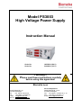
Model PS3003
High Voltage Power Supply
Instruction Manual
Order No
Order No
10553003 (230 V)
31063003 (115 V)
!! Warning !!
Please read these instructions carefully
before using this apparatus!
Biometra GmbH
Rudolf-Wissell-Str. 30
D-37079 Goettingen
Tel:
+49 (0)5 51 50 68 6-0
Fax:
+49 (0)5 51 50 68 6-66
e-mail: [email protected]
internet: http://www.biometra.de
Service Department
Rudolf-Wissell-Str. 14-16
D-37079 Goettingen
Tel.: +49 (0)5 51 50 68 6-10 or -12
Fax.: +49 (0)5 51 50 68 6-11
e-mail: [email protected]
This document describes the state at the time of publishing. It needs not necessarily agree
with future versions.
Subject to change!
PS3003 HV Power Supply, 2011/03
1 Contents
1
CONTENTS ....................................................................................................................1
2
INTRODUCTION.............................................................................................................2
3
NOTICE TO CUSTOMER ...............................................................................................2
4
SAFETY..........................................................................................................................4
4.1
4.2
4.3
DEFINITION OF SYMBOLS ..............................................................................................4
SAFETY INSTRUCTIONS .................................................................................................4
ENVIRONMENTAL SAFETY CONDITIONS ..........................................................................6
5
SPECIFICATIONS ..........................................................................................................7
6
DELIVERY PARTS .........................................................................................................8
6.1
6.2
6.3
6.4
7
CONTENT......................................................................................................................8
UNPACK AND CHECK ....................................................................................................8
LOCATION.....................................................................................................................8
CONNECTION WITH THE AC MAINS ................................................................................8
OPERATING INSTRUCTIONS.......................................................................................9
7.1
7.2
7.3
7.4
7.5
7.6
7.7
7.8
7.9
8
CONTROL ELEMENTS ....................................................................................................9
INSTALLATION.............................................................................................................10
OPERATION IN CONSTANT VOLTAGE............................................................................10
OPERATION IN CONSTANT CURRENT ...........................................................................11
OPERATION IN CONSTANT WATTS ...............................................................................11
CHOOSING SAFE OPERATING LIMITS ...........................................................................12
AUTOMATIC CROSSOVER ............................................................................................13
USER PROTECTION AND SAFETY .................................................................................13
POWER FAILURE DURING THE RUN..............................................................................13
MAINTENANCE AND CLEANING ...............................................................................14
8.1
8.2
MAINTENANCE ............................................................................................................14
CLEANING ..................................................................................................................14
9
TROUBLESHOOTING GUIDE .....................................................................................15
10
SERVICE ......................................................................................................................16
11
EQUIPMENT DECONTAMINATION CERTIFICATE....................................................17
12
NOTE FOR DISPOSAL OF ELECTRIC/ELECTRONIC WASTE .................................19
13
NOTICES ......................................................................................................................20
14
EC - DECLARATION OF CONFORMITY.....................................................................21
15
WARRANTY .................................................................................................................22
2 Introduction
The Biometra Model PS3003 High Voltage Power Supply is recommended for DNASequencing, Isoelectric Focusing and Polyacrylamide Gel Electrophoresis. Additional it can be
used for Agarose Gel Electrophoresis. The use for Semi-dry and Tank blotting may be limited.
The Model PS3003 High Voltage Power Supply is intended for use with any electrophoresis
applications designed to operate below 3,000 volts and 300 milliamps DC. Two sets of outputs
operate in parallel to provide 10 to 3,000 volts, 1 to 300 milliamps and 1 to 300 watts in
constant voltage, constant current or constant power mode. Voltage setting is adjustable in 10
V steps. Current and power setting is adjustable in steps of 1mA and 1W.
Three separate displays provide output voltage, current and power readings.
3 Notice to Customer
Read and carefully follow manual instructions.
Do not alter equipment. Failure to adhere to these directions could result in
personal and/or laboratory hazards, as well as invalidate equipment warranty.
This power supply is authorized for laboratory research use only. The product
has not been qualified or found safe and effective for any human or animal
diagnostic or therapeutic application. Uses for other than the labeled intended
use may be a violation of applicable law.
The model PS3003 High Voltage Power Supply is equipped with an automatic restart
system in case of mains failure.
When the power returns, an audible alarm sounds for 10 seconds and the power
automatically restarts with the previous set values.
If during the power failure the electrophoresis unit is disconnected from the power
supply, the alarm still sounds when the mains supply returns. Because no load is
connected the power supply will immediately shutdown and set the output to zero.
Direct reading of programmed set values and actual values before and during the
cycle.
Volt, mA and Watts adjustable during a cycle.
Stabilisation and automatic crossover between the parameters according to the set
limitation values and when output limits are reached. 3 Red LED indicate the constant
mode.
2
PS3003 HV Power Supply Instruction Manual, Version 2011/03
3 operating modes: constant voltage - constant current – constant power
Settings by tactile switches and moisture resistant membrane panel
Battery-backed memory feature "save" last output set values in the event of a power
failure or when the run is terminated and the unit is turned off.
3 red LED Displays for set and output Volt, Current and power values.
3 recessed safety output jacks allow simultaneous operation of 3 electrophoresis
units.
Fault detection and 500μA current leakage detection or no load automatically shuts
down output and indicates the fault by yellow LED blinking.
PS3003 HV Power Supply Instruction Manual, Version 2011/03
3
4 Safety
4.1 Definition of Symbols
Symbol
Definition
Caution: Read these operating instructions carefully before use and pay
particular attention to sections containing this symbol.
Danger! High Voltage!
Fragile!
4.2 Safety Instructions
Read these operating instructions carefully before use:
DANGER! HIGH VOLTAGE! This power supply has been designed for use as a
source of DC power for electrophoresis. It is capable of generating lethal currents. This
unit should always be operated only by qualified and trained personell and with
extreme caution. Careless handling could result in electrical shock.
4
•
Take care as the mode of operation of the Power Supply is continuous.
•
Use only as specified by the operating instructions, or the intrinsic protection may be
impaired.
•
Never operate damaged equipment. Do not use the unit without the cover in place or
with any possible short circuit. If the power supply emits smoke or continually blows
the main fuses, turn off the power supply and disconnect the AC line and power cord.
•
For additional information, please call the Biometra Technical Service Deaprtment or
your local distributor. Never attempt to remove the outer casing or make any repairs to
the unit.
•
The unit must be earthed. Use only the line cord supplied with the unit for safe
operation. (Connect the device to a properly grounded outlet only!)
PS3003 HV Power Supply Instruction Manual, Version 2011/03
•
Check the mains plug of the line cord to make sure it is equipped with a protection fuse
not exceeding 3 A. The use of a line cord other than this or the one supplied by
Biometra may result in user hazard.
•
The AC power cord has a three-pronged plug which must be connected to a grounded
line voltage receptacle. Do not use a two-wire receptacle with an adapter. This could
create a serious electrical hazard for persons using the unit.
•
Use the correct voltage AC power outlet for the power supply. Be sure to always plug a
110 VAC power supply into a 105/125-VAC, 50/60 Hz line, and use a 210/250-VAC,
50/60 Hz line with a 240V unit.
•
For connection between the power supply and the electrophoresis equipment, use only
the safety output power cords equipped with black and red recessed plugs as supplied
with the Biometra electrophoresis equipment or power cords that meet the legal
requirements.
•
Check the power cords and the black and red recessed safety jacks periodically to
make sure that they are in good condition. Do not use cords which are cracked, nicked
or in otherwise poor condition.
•
Always turn off the power supply before connecting or removing the power cords or
moving an electrophoresis apparatus.
•
Handle one power cord at a time, with one hand only, when connecting or removing
DC power cords at the power output terminals.
•
It is also recommended to use electrophoresis equipment that can only be connected
when the safety lids are closed.
•
Never place any objects other than high voltage connectors rated to 3,000V into the
output jacks.
•
Site the unit such that the rear panel has at least 20 cm of clearance to provide for
adequate unit ventilation.
•
Make sure the power supply is located in a safe and dry place, in proximity to the
electrophoresis devices powered. Keep away from liquids. Should a liquid penetrate
the Power Supply, disconnect the device immediately.
•
Ensure that the mains switch is easily accessible during use.
•
Before moving, disconnect at the power supply socket.
•
After transport or storage in humid conditions, dry out the unit before connecting it to
the supply voltage. During drying out the intrinsic protection may be impaired.
Do not operate the unit in a damp, humid atmosphere or in a fashion where condensed
moisture may short out electrical components.
PS3003 HV Power Supply Instruction Manual, Version 2011/03
5
•
Before using any cleaning or decontamination method except those recommended in
this manual, check with the Biometra Service Department that the proposed method
will not damage the equipment.
4.3 Environmental Safety Conditions
The Model PS3003 High Voltage Power Supply is designed for the following
conditions:
•
•
•
•
6
Indoor use
Altitude up to 2000 m
Temperature 10 °C – 40 °C
Maximum relative humidity 80 % for temperature up to 31 °C decreasing
linearly to 50 % relative humidity at 40 °C
PS3003 HV Power Supply Instruction Manual, Version 2011/03
5 Specifications
Mains supply voltage fluctuations not to exceed ± 10% of the normal voltage
Mains supply, 110V model :
Mains supply, 220V model :
Fuse value in the mains plug (UK):
Rated input power/current
V - mA – W setting and regulation
range
90 – 130 V; 50 – 60 Hz; T4A fuses
180 – 260 V; 50 – 60 Hz; T2A fuses
3A
400 VA
10 - 3000 Volts ; 10 Volt step
1 - 300 mA; 1 mA step
1 – 300 Watts; 1 watt step
V - mA – Watts display range
0 - 3000 Volts ; 10 Volt step
0 - 300 mA; 1 mA step
0 – 300 Watts
Mode of operation
Switching frequency
Output regulation stability
Continuous
23 kHz
± 0,2% FS ± ½ digit
Minimum no regulated output
5 Volts; 15μA; 0,6 Watts
Minimum regulated output
10 Volts; 1 mA; 1 Watts
(load >10 kOhms)
Value display accuracy
± 0,2 FS ± ½ digit
Mains failure during the run :
Buzzer, then automatic restart with
previous set values
Fault detection
Output supply stop, buzzer
Yellow LED flashing
Fault status
Output to earth leakage
Output open circuit
Output short circuit
No regulation (Overheating, power
circuit fault)
Earth leakage detection level
Output to earth impedance
500 μA
10Mõ min bypassed by 1nF max
Size
34 cm x 27 cm x 11 cm
(DxWxH)
Weight
5 kg
PS3003 HV Power Supply Instruction Manual, Version 2011/03
7
6 Delivery parts
6.1 Content
•
•
•
Model PS3003 High Voltage Power Supply
Manual
Power Cord
6.2 Unpack and Check
Unpack and carefully examine the Model PS3003 High Voltage Power Supply. Report any
damage to BIOMETRA or your local distributor.
Save all packing material if damage is found.
Do not attempt to operate this device if physical damage is present.
If you would like to send the unit back to us, please read the return instructions.
6.3 Location
Make sure that the unit is set up in a location where it is protected from physical damage,
moisture, corrosive agents, and extreme temperatures. Make sure that the fan at the rear is
not obstructed; leave about 10-cm space behind the unit. The unit should be readily
accessible for safe operation.
6.4 Connection with the AC Mains
Connect the unit to the AC mains carrying the appropriate specified voltage (V) in accordance
with the rating label affixed to the back of the unit. Ensure that the main receptacle and the
power supply plug both have the proper three-wire (grounded or earthed) connections.
8
PS3003 HV Power Supply Instruction Manual, Version 2011/03
7 Operating Instructions
In order to achieve the greatest efficiency and effectiveness from this unit, read this section in
its entirety before setting up or operating the power supply unit and carefully review the
following figure to ascertain the location of the power supply’s controls and features.
7.1 Control Elements
2
3
4
5
6
7
8
Preset
1
10
14
11
13
15
9
12
No.
DESCRIPTION
FUNCTION
1
2
3
4
5
6
7
8
9
10
11
12
13
14
15
Main power switch
Voltage output LED
Current output LED
Power output LED
STOP switch
START switch
STOP LED
START LED
Fault LED
Volt LED
mA LED
Watt LED
Setting switches
High Voltage output jacks
PRESET switch
Turns on unit (located on the right side)
Displays actual output in Volts
Didplays actual output in mA
Displays actual output in Watts
Terminates output
Begins output
Indicated STOP ouput
Indicated START output
Indicated ground leakage, no load or short circuit
Indicates constant voltage mode
Indicated constant current mode
Indicated constant power mode
Increase/decrease set point
Red = positive ; Black = negative
Displays output preset values
PS3003 HV Power Supply Instruction Manual, Version 2011/03
9
7.2 Installation
1. Connect the AC line cord to a grounded, 3-prong wall outlet.
2. Connect the power supply to an electrophoresis device using the power cords supplied.
3. Press the main POWER switch to turn the power supply on. The STOP LED (red) will
illuminate, and the output LEDs will display zeros.
7.3 Operation in Constant Voltage
1. Place the power supply on a sturdy, level surface in a safe, dry place away from laboratory
traffic. Controls must be easily accessible and sufficient space must be available nearby for
the electrophoresis unit(s) to be used with the power supply. The fan intake in the back and
exhaust on the bottom must remain unobstructed.
Note: Allow at least 8 h for the unit to equilibrate if it is moved into or out of a cold room. It
must be completely dry before using.
2. The electrophoresis chamber should be set up, than filled with buffer, before plugging the
chamber’s leads into the appropriate positive and negative 4-mm sockets on the power supply
unit.
Note: Sample can be added before or after adjusting power supply settings.
3. Switch on the power supply using the Power On/Off switch. The Volts display, Milliamps
display, and Watts display will all indicate zero.
Notes on General Operation: The output of the unit is controlled by three separate operating
parameters. An operating limit, with a value above zero, must be set for voltage, milliamps,
and watts to generate an output. When the power supply unit is activated, the output of the
power supply will steadily increase until an operating limit is reached. Once an operating limit
is reached, one of the three red At Limit lights will illuminate. The light will indicate which
operating limit has been reached first and which mode of control has been established.
4. Using the Volts setting switch, select the operating voltage limit by using the ▲ or ▼
adjustment switch until the desired value appears on the Volts display. Using the ▲ switch will
increase the displayed value in 10-V increments. Using the ▼ switch will reduce the displayed
value in the same manner.
As soon as one of these adjustment switches is activated, the output LED will display output
set values rather than actual output values. When they are released, the output LED will
display output set values for 3 seconds, and then will display actual output (All zero since
output has not yet be started).
Note: The DC output must be off to change the output settings.
5. Using the Milliamps adjustment switches and Watts adjustment switches, select the desired
operating limits for milliamps and watts, respectively. The method used to select these values
is the same method used to select the operating voltage limit.
Warning: The Model PS 3003 High Voltage Power Supply is capable of producing output
levels well in excess of the maximum safe operating limits for most electrophoresis chambers.
It is important to determine the safe operating limits for milliamps and watts. Section
“Choosing Safe Operating Limits” has been included to guide the user in selecting proper
operating parameters.
6. Press the START switch. The START LED (green) will illuminate, and the output LED’s will
display the actual values simultaneously. The DC output, as indicated by the three displays,
10
PS3003 HV Power Supply Instruction Manual, Version 2011/03
should rapidly increase until the operating voltage limit is reached. At this point the Voltage
mode LED will illuminate, indicating the parameter controlling output.
7. Slight increases or decreases in output readings for those parameters not "limiting" will
occur as the experiment progresses. These changes accurately represent changes in the
resistive load ( electrophoresis unit ) due to changes in temperature, buffer capacity, etc. This
is to be expected.
8. To view the output set values during the run, press the PRESET switch. The LED’s will
display the output set values as long as this switch is pressed. Once the PRESET switch is
released, the led will display the output set values for three seconds, and then switch back to
displaying the actual output values.
9. It is impossible to change the values during the run without pressing the STOP switch.
During the run, as soon as one of these adjustment switches is activated, the output LED’s will
display output set values.
10. To change the output set values during the run, press the STOP switch. Increase or
decrease with the adjustment switches until the appropriate output set value is reached. In
START status, when the PRESET switch is depressed, the LEDs will display the output set
values during three seconds and then switch back to displaying the actual output values.
11. If the non-controlling output set values is reached during the course of the run, the power
supply will automatically crossover to the new mode and control output relative to that mode.
The appropriate mode LED will illuminate.
12. If automatic crossover is desired during the run, adjust the output set value of the second
controlling parameter to the desired setting. When actual output relative to the second
controlling parameter equals its output set value, the output will cross over from the first
controlling parameter to the second.
13. At the end of electrophoresis, turn off the power supply using the DC Output STOP key.
Wait one minute before disconnecting the leads.
Note: Turn the main power switch off when the unit is not in us
7.4 Operation in Constant Current
The method used to set the power supply in constant current is the same as the method used
for constant voltage. The only difference involves the selection of an operating limit for current
which, as the output increases, is attained before the operating limits for voltage or watts.
7.5 Operation in Constant Watts
The method used to set the power supply in constant watts is the same as the method used to
set constant voltage with one notable difference. The difference involves the selection of an
operating limit for watts which, as the output increases, is attained before the operating limits
for voltage or current.
PS3003 HV Power Supply Instruction Manual, Version 2011/03
11
7.6 Choosing Safe Operating Limits
Electrophoresis chambers are generally designed for a relatively specific purpose. For
example, submarine chambers use agarose gels to separate DNA or RNA fragments, while a
DNA sequencing chamber is almost always used to separate DNA in a denaturing
polyacrylamide gel. In each case, the voltage, milliamp, and wattage requirements are well
defined within a reasonable range of values. In cases such as these, the user can safely
assume that the manufacturer has designed the chamber to withstand the voltage and heat
energy necessary to perform the electrophoretic separation when standard protocols are
followed.
Some types of electrophoresis chambers are specifically designed to be multipurpose
devices. For example, a vertical slab gel chamber could be used for anything from DNA
sequencing to isoelectric focusing, depending on the gel type and buffer system used.
Choosing safe operating limits for a chamber of this type requires a higher degree of caution.
Chamber manufacturers normally rate their product for maximum voltage and/or maximum
wattage. Whenever possible, contact the manufacturer and request this information.
Whether you use special purpose or multipurpose chambers, the maximum operating
temperature the chambers will withstand is a critical aspect of safe operation. Most
electrophoresis chambers (with a few notable exceptions) are made of acrylic and plastic and
should operate below a temperature of 35°C. If there is a lack of information about the
capabilities of the chamber being used, regular monitoring of the operating temperature is
recommended. This should be accomplished without coming into physical contact with the
chamber when voltage is applied. Use the procedure listed below to select operating
parameters.
1. Set voltage as described in steps 1–4 for operation in Section 7.3 “Operation in Constant
Voltage”
2. Using the Milliamps and Watts adjustment switches, select the maximum operating limits of
300 mA and 300 W, respectively.
3. Press the START key. The Start LED (green) should illuminate and the DC output, as
indicated by the three displays, should rapidly increase until the operating voltage limit is
reached. At this point the Voltage mode LED should illuminate and should be the only ‘at limit’
light illuminated.
4. Once the power supply has reached the operating voltage limit, note the actual number of
milliamps and watts displayed and press the DC Output STOP key.
5. Add 15 mA and 10 W to the actual values noted earlier. Using the adjustment switches, set
the operating limits to the new values.
6. Press the DC Output START key. The Start LED (green) should illuminate and the DC
output displays should rapidly increase until the operating voltage limit is reached. At this point
the Voltage mode LED should illuminate and should be the only ‘at limit’ light illuminated.
Note: It may be necessary to readjust the watt or milliamp operating limit during
electrophoresis to ensure that the entire procedure is performed at a constant voltage. This
readjustment, if necessary, is required to compensate for large changes in resistance which
occur during certain types of electrophoresis (see Section 7.7 “Automatic Crossover”).
Note: To view the output settings during electrophoresis, press the preset key. The LED’s will
display the set output values as long as the key is pressed. Once released, the LED’s will
display the set values for 3 seconds and then switch to the actual output values.
12
PS3003 HV Power Supply Instruction Manual, Version 2011/03
7.7 Automatic Crossover
For some electrophoresis conditions, a function of this power supply unit known as automatic
crossover will occur. Automatic crossover is the ability of the unit to change the mode of
operation during the course of an experiment. As conditions of buffers and gels change during
a run, a constant voltage run may, for example, become limited by current or power if the limit
for either of these other values is reached. This automatic crossover process is used to
protect both the experiment and equipment.
7.8 User Protection and Safety
A yellow LED indicates a fault situation and cut off the power supply:
1. Overload.
2. Output to earth leakage
3. Output open circuit
4. Chamber lead (s) disconnected or defective.
5. Output short circuit.
Press STOP to resume and look for the wrong situation.
Press START to run again.
7.9 Power Failure During the Run
The power supply automatically RESTARTS when the power is operating again after a power
failure or repetitive micro failures during a cycle.
When the mains is operating again after the failure, an audible alarm rings and the STOP LED
blinks for 10 seconds.
Then the power supply RESTARTS automatically with respect to the set values.
PS3003 HV Power Supply Instruction Manual, Version 2011/03
13
8 Maintenance and Cleaning
8.1 Maintenance
There are no internal operator serviceable parts in this Power supply.
This power supply uses all solid-state components and should require no maintenance or
recalibration under normal use. If the power should fail, the unit must be returned to the
Biometra Technical Service or your local distributor.
As with any laboratory instrument, adequate care ensures consistent and reliable
performance.
8.2 Cleaning
The power supply may be cleaned as required when the main supply is
isolated.
The power supply must not be immersed in water. The unit can be wiped with a soft cloth,
dampened with water or with tissues impregnated with 70% Iso-propyl alcohol.
Do not allow water to enter the case.
Abrasive cleaners, window sprays or rough cloths may damage the surface and should be
avoided.
Do not expose the surface to phenol, acetone, benzene, halogenated hydrocarbon solvents or
undiluted laboratory alcohols.
Avoid prolonged exposure of the power supply to UV light.
A soft, dry cloth may be used to dry the unit.
Before using any decontamination or cleaning method except that recommended, check with
our Service Department that the proposed method will not damage the equipment.
14
PS3003 HV Power Supply Instruction Manual, Version 2011/03
9 Troubleshooting Guide
CONDITION
PROBABLE CAUSE
COMMENT
Display fails to illuminate
when the POWER switch
is put on.
Fuses have blown
See Warning below
The desired MODE is not
flashing.
One of the other
parameters is
limiting output.
Increase the output set
value of the parameter
controlling output until
the desired output
mode is controlling.
Two different modes are
blinking alternatively.
Settings for both
parameters are too
close to the actual
output.
Increase the set value
for the mode you do not
wish to be limiting.
Under constant power mode
Voltage and current output
are not stable.
Load, gel resistance are
changing. This usually
happens when prerunningthe gel.
Disregard slight
fluctuations.
Displays will stabilize as gel
equilibrates.
Increase or decrease W
Set value by one or two
Watts to stabilize.
Warning:
Never attempt to remove the outer casing or make any unit repairs.
Should the power supply fail, DO NOT remove the outer case of the unit and attempt any
repairs.
Contact Biometra or your local distributor if the need for repair or servicing should arise.
PS3003 HV Power Supply Instruction Manual, Version 2011/03
15
10 Service
Should you have any problems with this unit, please contact our service department or your
local Biometra dealer:
Biometra biomedizinische Analytik GmbH
Service Department
Rudolf-Wissell-Straße 14 - 16
D-37079 Göttingen
Germany
Phone:
+49 – (0)5 51 / 50 68 6 – 10 or -12
Fax:
+49 – (0)5 51 / 50 68 6 – 11
e-mail:
[email protected]
Attention:
If you would like to send the unit back to us, please read the following instructions.
Instructions for return shipment
•
Return only defective devices. Please contact the Technical Service Department at
Biometra (Phone: ++49 – (0)5 51 / 50 68 6 – 10 or -12) to get an Return Authorization
Number (RAN number).
•
Use the original box or a similarly sturdy one.
•
Label the outside of the box with “CAUTION! SENSITIVE INSTRUMENT!” and the RAN
number sticker. Deliveries without RAN number cannot be accepted!
•
Please enclose a precise description of the fault, which also reveals during which
procedures the fault occurred, if possible.
Important:
Clean all parts of the instrument from residues, and of biologically dangerous,
chemical and radioactive contaminants. Please include a written
confirmation that the device is free of biologically dangerous and radioactive
contaminants in each shipment. If the device is contaminated, it is possible that
Biometra will be forced to refuse to accept the device.
•
The sender of the repair order will be held liable for possible losses resulting from
insufficient decontamination of the device.
•
Please enclose a note which contains the following:
a) Sender’s name and address,
b) Name of a contact person for further inquiries with telephone number.
16
PS3003 HV Power Supply Instruction Manual, Version 2011/03
11 Equipment Decontamination Certificate
To enable us to comply with German law (i.e. §§28 and 80 StrlSchV, §17 GefStoffV and §19
ChemG) and to avoid exposure to hazardous materials during handling or repair, please
complete this form, prior to the equipment leaving your laboratory:
COMPANY / INSTITUTE _________________________________________________________
ADDRESS
PHONE NO
_________________________________________________________
________________________
FAX NO__________________________
E-MAIL _______________________________________________________________________
EQUIPMENT
If on loan / evaluation
Model
Serial No
______________
______________
______________
______________
______________
______________
______________
______________
Start Date: __________________
Finish Date __________________
Hazardous materials used with this equipment
_______________________________________________________________________________
_______________________________________________________________________________
_______________________________________________________________________________
Method of cleaning / decontamination
_______________________________________________________________________________
_______________________________________________________________________________
_______________________________________________________________________________
The equipment has been cleaned and decontaminated:
NAME ___________________________________
POSITION _________________________
(HEAD OF DIV./ DEP./ INSTITUTE / COMPANY)
SIGNED __________________________________
DATE _____________________________
PLEASE RETURN THIS FORM TO BIOMETRA GMBH OR YOUR LOCAL BIOMETRA
DISTRIBUTOR TOGETHER WITH THE EQUIPMENT.
PLEASE ATTACH THIS CERTIFICATE OUTSIDE THE PACKAGING. INSTRUMENTS WITHOUT
THIS CERTIFICATE ATTACHED WILL BE RETURNED TO SENDER.
PS3003 HV Power Supply Instruction Manual, Version 2011/03
17
General Information for Decontamination:
Please contact your responsible health & safety officer for details.
Use of radioactive substances:
Please contact your responsible person for details.
Use of genetically change organism or parts of those:
Please contact your responsible person for details.
18
PS3003 HV Power Supply Instruction Manual, Version 2011/03
12 Note for Disposal of Electric/Electronic Waste
This symbol (the crossed-out wheelie bin) means, that this product should be
brought to the return systems and/or separate systems available to end-users
according to yours country regulations, when this product has reached the end
of its lifetime!
For details, please contact your local distributor!
This symbol applies only to the countries within the EEA*.
*EEA = European Economics Area, comprising all EU-members plus Norway, Iceland
and Liechtenstein.
PS3003 HV Power Supply Instruction Manual, Version 2011/03
19
13 Notices
________________________________________________________________________________
________________________________________________________________________________
________________________________________________________________________________
________________________________________________________________________________
________________________________________________________________________________
________________________________________________________________________________
________________________________________________________________________________
________________________________________________________________________________
________________________________________________________________________________
________________________________________________________________________________
________________________________________________________________________________
________________________________________________________________________________
________________________________________________________________________________
________________________________________________________________________________
________________________________________________________________________________
________________________________________________________________________________
________________________________________________________________________________
________________________________________________________________________________
________________________________________________________________________________
________________________________________________________________________________
________________________________________________________________________________
________________________________________________________________________________
________________________________________________________________________________
________________________________________________________________________________
________________________________________________________________________________
________________________________________________________________________________
________________________________________________________________________________
__________________________________________________________________________________
20
PS3003 HV Power Supply Instruction Manual, Version 2011/03
14 EC - Declaration of Conformity
EU - Konformitätserklärung
December 2007
im Sinne der EG-Richtlinie über elektrische Betriebsmittel zur Verwendung innerhalb bestimmter
Spannungsgrenzen 73/23/EWG
following the EC directive about electrical equipment for use within certain limits of voltage 73/23/EEC
und / and
im Sinne der EG-Richtlinie für die elektromagnetische Verträglichkeit 89/336/EWG.
following the EC directive about the electromagnetic compatibility 89/336/EEC.
Hiermit erklären wir, dass folgendes Power
Supply,
Herewith we declare that the following Power Supply,
Typ / type:
Best.-Nr. / Order No.
Model PS3003 High Voltage Power Supply
10553003 (230 V), 31063003 (115 V)
den grundlegenden Anforderungen der
corresponds to the basic requirements of
EG-Niederspannungsrichtlinie 73/23 EWG und der
EC low voltage directive 73/23 EEC and the
EG-Richtlinie über die elektromagnetische Verträglichkeit 89/336 EWG entsprechen.
EC directive about the electromagnetic compatibility 89/336/EEC.
Dr. Juergen Otte
Quality Manager
PS3003 HV Power Supply Instruction Manual, Version 2011/03
21
15 Warranty
This laboratory instrument is produced with the highest practical standards of materials,
workmanship, and design. The design and manufacture of parts have been conceived with
one purpose - to produce units which will give satisfactory service.
Biometra GmbH guarantees this unit to be free from defects in materials or workmanship
under normal use or service for 24 month from date of shipment.
If, during this time, this unit proves defective in materials or workmanship, Biometra GmbH will
repair or replace it free of charge if returned to us prepaid.
This guarantee does not cover damage in transit, damage caused by carelessness, misuse or
neglect, or unsatisfactory performance as a result of conditions beyond our control; or
consequential losses as a result of failure of our product.
Biometra GmbH
Rudolf-Wissell-Str. 30
D-37079 Göttingen
Germany
Phone: +49 – (0)5 51 / 50 68 6-0
Fax: +49 – (0)5 51 / 50 68 6-66
e-mail: [email protected]
internet: http://www.biometra.de
22
Service Department
Rudolf-Wissell-Str. 14-16
D-37079 Göttingen
Germany
Phone: +49 – (0)5 51 / 50 68 6-10 or -12
Fax.: +49 – (0)5 51 / 50 68 6-11
e-mail: [email protected]
PS3003 HV Power Supply Instruction Manual, Version 2011/03